

Page 1
FireStingO2-Mini-ST
OPT I C AL OXY G EN OEM-M O D ULE
WI T H UART - IN T ERFA C E & ANAL O G OUTPU T
FOR F I BE R-OPT IC S E NS O RS
MAN U AL
Page 2

Document Version 1.04
The FireStingO2-Mini-ST is manufactured by
PyroScience GmbH
Hubertusstr. 35
52064 Aachen
Germany
Phone +49 (0)241 5183 2210
Fax +49 (0)241 5183 2299
Email info@pyroscience.com
Internet www.pyroscience.com
Registered: Aachen HRB 17329, Germany
ii
Page 3

TAB L E OF CO N T ENT
1 INTRODUCTION ...................................................................... 1
2 SAFETY GUIDELINES ............................................................... 2
3 OVERVIEW ..............................................................................4
3.1 OPTICAL PORT FOR OXYGEN SENSORS .......................................... 4
3.2 SUPPLEMENTARY INTERNAL SENSORS ........................................... 6
3.3 EXTERNAL TEMPERATURE SENSOR ............................................... 7
4 ELECTRICAL CONNECTORS .................................................... 9
4.1 CONNECTOR X1: POWER + DIGITAL INTERFACE ............................. 10
4.2 CONNECTOR X2: ANALOG OUTPUT ............................................ 11
5 OPERATION VIA THE UART-INTERFACE ................................ 12
5.1 FULL-CONTROL MODE ............................................................. 12
5.2 AUTO-MODE ........................................................................... 13
6 OPERATION VIA THE USB-INTERFACE CABLE ........................ 15
6.1 SOFTWARE INSTALLATION ......................................................... 15
6.2 USING THE PYRO OXYGEN LOGGER SOFTWARE ............................. 16
7 SPECIFICATIONS ................................................................... 18
iii
Page 4

1 Introduction
The FireStingO2-Mini-ST is a high precision optical oxygen meter
for liquid or gas samples, which is based on the opto-electronics of
the successful USB-device FireStingO2 from PyroScience. Most
features of the FireStingO2-Mini-ST are identical to the
FireStingO2. Therefore, for a general introduction it is highly
recommended to consult additionally the detailed manual of the
FireStingO2. Here we will cover mostly the differences of the
FireStingO2-Mini-ST compared to the FireStingO2.
The FSO2-Mini-ST is compatible to most oxygen sensors types
available from PyroScience.
Further, it includes also internal high-precision sensors for
(i) ambient atmospheric pressure, (ii) relative humidity of the
ambient air, and (iii) the temperature of the ambient air.
Additionally, an external temperature probe (PT100) used for
automatic temperature compensation of the oxygen measurement
can be soldered directly to the module (e.g. item TSUB21-NC).
This manual provides only specific information needed for the
FireStingO2-Mini-ST. It is highly recommended to study carefully
the manual of the USB-device FireStingO2 in order to get a
general introduction in optical oxygen measurements and the
related sensor types.
1
Page 5

2 Safety Guidelines
In order to guarantee an optimal performance of the FireStingO2-
Mini-ST please follow these operation instructions and safety
guidelines. If any problems or damage evolve, please disconnect
the instrument immediately, mark it to prevent any further use and
consult PyroScience for repair or maintenance service. The
FireStingO2-Mini-ST should not be manipulated or opened by
unauthorized persons (except for the needed steps in order to
solder the external PT100 to the internal PCB-board), only by
PyroScience or persons advised directly from PyroScience.
Please note that opening the housing (except removing the front
cap for accessing the solder pads for the external temperature
sensor) will void the warranty. There are no serviceable parts inside
the device.
The FireStingO2-Mini-ST and the sensors should be kept and
stored outside the reach of children in a secure place under dry and
clean conditions at room temperature, avoiding moisture, dust,
corrosive conditions and heating of the instrument. This device is
not intended for medical, military or other safety relevant areas. It
should be used in the laboratory by qualified personal only
following the operation instructions and safety guidelines of this
manual.
Please follow the appropriate laws and guidelines for safety like
EEC directives for protective labor legislation, national protective
labor legislation, safety regulations for accident prevention and
safety data-sheets from manufacturer of chemicals used during
measurements.
When used in the field, the environmental conditions (like high
humidity, dust, exposure to direct solar radiation) may cause
damage or interference of the FireStingO2-Mini-ST, which is on
the user's authority.
2
Page 6

Before using the FireStingO2-Mini-ST and its sensors, read
carefully the instructions and user manuals.
In case of problems or damage, disconnect the instrument and
mark it to prevent any further use! Consult PyroScience for
advice! There are no serviceable parts inside the device. Please
note that opening the housing will void the warranty!
The FireStingO2-Mini-ST is not watertight, is sensitive to
corrosive conditions and to changes in temperature causing
condensation. Avoid any condition (e.g. direct sun light) causing
a heating of the device above 50°C (122°F).
Calibration and application of the sensors is on the user’s
authority, as well as data acquisition, treatment and
publication!
The sensors and the oxygen meter FireStingO2-Mini-ST are not
intended for medical, diagnostic, therapeutic, or military
purposes or any other safety-critical applications. The sensors
must not be used for applications in humans and must not be
brought in direct contact with foods intended for consumption
by humans.
The FireStingO2-Mini-ST and sensors should be used in the
laboratory by qualified personnel only, following the user
instructions and the safety guidelines of the manuals, as well as
the appropriate laws and guidelines for safety in the laboratory!
Keep the sensors and the oxygen meter FireStingO2-Mini-ST out
of reach of children!
3
Page 7

3 Overview
Fig. 1 provides an overview of the FSO2-MINI-ST. The overall
dimension of the module is 67 x 25 x 25 mm (without the optical
port). Two M3 threads can be found at the bottom for mounting
the module in customized setups. Please note, that one of the M3
threads is hidden below the type label. The position of that M3
thread is roughly indicated on the type label. Just penetrate the
type label at this position with e.g. a needle or nail in order to
access the M3 thread.
3.1 Optical Port for Oxygen Sensors
The FSO2-MINI-ST provides an ST-connector as known from the
USB-device FireStingO2. Thus, all optical oxygen sensors available
for the FireStingO2 (e.g. needle-type sensors, robust probes, fibers
for read-out of sensor spots, flow through cells, respiration vials)
can be directly connected to the FSO2-MINI-ST. Please refer to the
manual of the FireStingO2 for further details.
4
Page 8
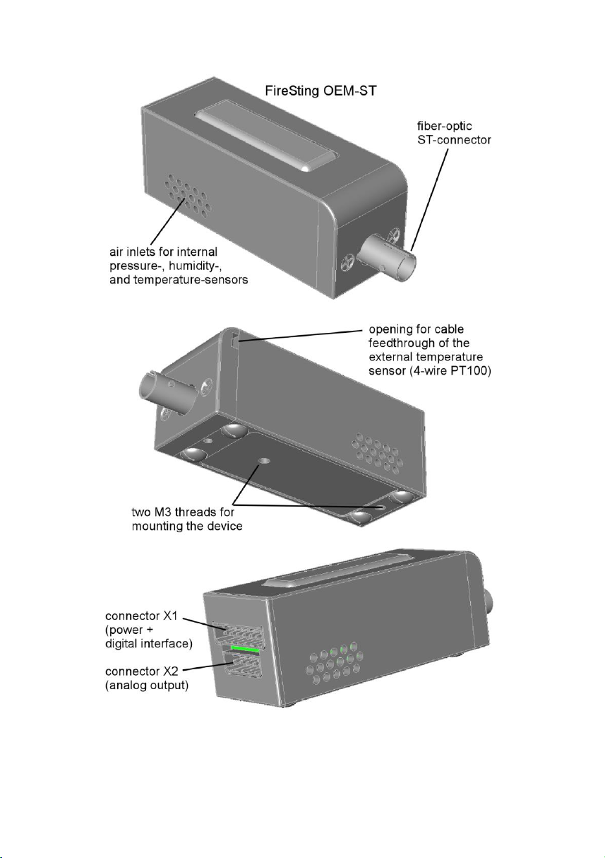
Fig. 1 Drawing of the FSO2-MINI-ST
5
Page 9

3.2 Supplementary Internal Sensors
Besides the very oxygen sensor, the FireStingO2-Mini-ST provides
three other built-in high precision sensors:
(1) An internal atmospheric pressure sensor for measuring
the ambient air pressure,
(2) an internal sensor for measuring the relative humidity of
the ambient air, and
(3) an internal temperature sensor measuring the
temperature of the ambient air.
These three internal sensors are positioned within the module
close to the air inlets on both sides of the housing. In order to get
reliable data about the ambient air from these internal sensors, it is
important to ensure free air access around the air inlets. The
pressure and the humidity sensors will give in most situations
reliable data about the ambient air. However, the readings of the
internal temperature sensor should be interpreted more carefully.
First, the internal heating by the electronics typically increases the
internal temperature by about 1ºC. This offset can get much
worse, if the module is additionally exposed to e.g. strong
illumination. It is on the user’s authority to interpret the internal
temperature sensor with care.
The internal humidity sensor can be useful if a simple air calibration
of the oxygen sensor shall be performed in ambient air. For this
calibration type the relative humidity of the ambient air has to be
known, because the humidity changes the actual volume fraction
of oxygen in the ambient air.
Similarly, the internal pressure sensor is generally useful for any air
calibration performed under ambient air pressure, because the
actual air pressure has to be known during the calibration. But the
pressure sensor can be also used during the oxygen measurements
6
Page 10

for automatic pressure compensation (useful for the following
oxygen units: %air sat, %O2, µmol/L, mg/L).
3.3 External Temperature Sensor
The oxygen measurement is generally temperature dependent.
Therefore, the FireStingO2-Mini-ST provides a built-in
temperature compensation, which should be activated if the
temperature changes during measurements more than ca. 1ºC.
Although under certain circumstances the internal temperature
sensor can be also utilized for such a compensation, the first choice
should be always an external 4-wire PT10o temperature sensor
placed directly within the sample where the oxygen concentration
is measured. The FireStingO2-Mini-ST provides a high-precision
sensor interface which can be directly connected to any standard
4-wire PT100.
Fig. 2 Connecting a 4-wire PT100 temperature sensor to the OEM module
The PT100 has to be soldered directly to the electronics board
within the module. In order to access the solder pads, the front cap
of the housing has to be removed by unscrewing the two screws
besides the optical port. Please refer to Fig. 2 how to connect the
7
Page 11

4-wire PT100. The front cap provides a small cable feedthrough
where the cable of the external PT100 can penetrate the housing.
When closing the housing again, ensure that the solder points do
not get into contact to the aluminum housing.
NOTE: In order to minimize potential electrical noise coupling into
the external temperature sensor, the 4-wire cable should be
twisted and as short as possible. Cable lengths above 2m are not
recommended. For minimizing any noise further, the 4-wire cable
can be provided with an additional coaxial shield, which has to be
connected to ground.
8
Page 12

4 Electrical Connectors
The electrical interface of the FireStingO2-Mini-ST consists of the
two connectors X1 and X2 (Fig. 1). The package includes for both
connectors the connector plugs S1 and S2, also available from
"Phoenix Contact" item no. 1778887 and 1778861 (Fig. 3). Stripped
cable ends can be connected to S1 and S2 without any soldering or
crimping. When inserting or removing a stripped cable end
(stripping length 6 mm, max. core diameter 0.5 mm²) into one of
the connector holes of the connectors S1 or S2, an internal spring
mechanism has to be unlocked by pushing relatively strong with a
small screw-driver (flat-bladed 2mm in width) into the adjacent
rectangular hole (Fig. 3). Please note that pin 1 of the connectors is
positioned always at the right side of the connector (Fig. 3).
Fig. 3 Electrical connectors of the FireStingO2-Mini-ST
9
Page 13

4.1 Connector X1: Power + Digital Interface
Pin
Name
Function
Description
1
GND
Power
Ground
2
VCC
Power
Power supply
min. 3.5V max. 5.0V DC
max. 50 mA (typical 30 mA)
3
GND
Power
Ground
4
TXD
Digital Output
(0V or 3.3V)
Data transmission pin of the
UART interface
5
RXD
Digital Input
(0V or 3.3V)
(5V tolerant)
Data receive pin of the UART
interface
6
/AUTO
Digital Input
(0V or 3.3V,
internally pulledup to 3.3V)
Leave auto-mode pin
unconnected for normal
operation. Connect to GND
for auto-mode operation.
7
/TRIG
Digital Input
(0V or 3.3V,
internally pulledup to 3.3V)
Trigger input for triggering a
measurement in "triggered
auto-mode". The trigger is
activated at the moment,
when the unconnected pin is
tied to GND.
The pin configuration of the connector X1 is given in Tab. 1. Pins 13 are for power supply of the module. The transmit and receive
pins of the UART-interface are given at pins 4+5. The additional
pins 6+7 are only needed if the module should be operated in automode (see following chapter). In standard operation mode both
pins 6+7 should be left unconnected.
Tab. 1 Pin configuration of the connector X1
10
Page 14

4.2 Connector X2: Analog Output
Pin
Name
Function
Description
1
GND
Ground
2
AO_A
Analog Output
(0 – 2.5 V DC)
(14 bit resolution)
Analog Output Port A
(alternatively digital
alarm output)
3
AO_B
Analog Output
(0 – 2.5 V DC)
(14 bit resolution)
Analog Output Port B
(alternatively digital
alarm output)
4
AO_C
Analog Output
(0 – 2.5 V DC)
(14 bit resolution)
Analog Output Port C
(alternatively digital
alarm output)
5
AO_D
Analog Output
(0 – 2.5 V DC)
(14 bit resolution)
Analog Output Port D
(alternatively digital
alarm output)
The connector X2 provides 4 independent analog outputs with a
range of 0-2.5V DC at a resolution of 14 bits (Tab. 2). The 4 analog
outputs can be configured by the UART communication protocol
very flexible. The parameter given at each analog output can be
chosen (e.g. oxygen concentration in different units, signal
intensity of the oxygen sensor, ambient pressure, ambient
humidity, internal temperature, external temperature from
PT100), the scaling can be adjusted freely, and even an alarm
function can be configured. If an analog output is configured as an
alarm output, it will give 2.5V if a specific parameter is out of a
defined range (and 0V if it is within this range).
For further details please refer to the separately available
communication protocol.
Tab. 2 Pin configuration of the connector X2
11
Page 15

5 Operation via the UART-Interface
The FireStingO2-Mini-ST is operated via a standard UART
interface at 3.3V levels (5V tolerant) consisting merely of a receive
and a transmit line (connector X1, pins 4+5, see Tab. 1). The
configuration of the UART-interface is as follows:
19200 baud, 8 data bit, 1 stop bit, no parity, no handshake
The baud rate can be changed by a special command of the
communication protocol (refer to the communication protocol for
further information). However, after power cycling the module
always reverts to the standard baud rate of 19200.
There are two principal operation modes possible: (1) the fullcontrol mode and the (2) auto-mode. Please note that adjusting
the settings and performing any calibration can only be done in the
full-control mode.
5.1 Full-Control Mode
The standard operation mode of the module is the full-control
mode. The necessary electrical connections are shown in Fig. 4.
Fig. 4 Pin assignment in full-control mode
The full-control mode allows exploiting the full functionality of the
module. Each action of the module is triggered by transmitting a
12
Page 16

text-command via the UART interface. The measurement results
can be either read out via the same UART interface. Alternatively,
measurement results can be also read from the analog output.
For further details please refer to the separately available
communication protocol.
5.2 Auto-Mode
In the full-control mode each single measurement has to be
triggered by a specific command sent via the UART interface (e.g.
the MSR- or TMP-commands for measuring oxygen or
temperature, respectively). Alternatively, an auto-mode can be
activated by connecting pin 6 of connector X1 to ground (Fig. 5).
Fig. 5 Pin assignment in auto-mode
The auto-mode offers the possibility, (i) that the measurements
are automatically triggered periodically by an internal timer
(interval auto-mode) or (ii) that the measurements are triggered
13
Page 17

each time when pin 7 of connector X1 is tied to ground (triggered
auto-mode). The results of the measurements can be either read
from the transmit pin of the UART interface, or from the analog
outputs at connector X2.
NOTE: When the auto-mode is activated, the receive pin of the
UART interface has no function. The module will not respond to
any command sent to it.
The basic idea behind the auto-mode is that a fully configured and
calibrated module can be operated without the need of complex
communication protocols. However, the configuration (including
the configuration of the auto-mode!) and the calibration data have
to be adjusted in the full-control mode (or by using the USBinterface cable in combination with the comfortable windows
software Pyro Oxygen Logger; please refer to the next chapter).
The communication protocol offers a special command for storing
the current configuration and calibration data permanently in the
internal flash memory. Thus, a fully configured module can be
operated in auto-mode even if the power supply is intermediately
interrupted.
A typical application scenario would be the following: the
FireStingO2-Mini-ST could be configured and calibrated in a
"calibration lab" using the full-control mode (or the windows
software Pyro Oxygen Logger). The configuration and the
calibration data are stored in the internal flash memory. Then the
sensor is brought to the "field application" which can be a remote
place. By connecting pin 6 of the connector X1 to ground the
module starts measuring without the need of any UART
communication. The measurement results can be read out from
the analog output (or from a text-string sent via the UART transmit
line).
14
Page 18

For further details please refer to the separately available
communication protocol.
6 Operation via the USB-Interface Cable
For the operation of the FireStingO2-Mini-ST with a usual
Windows PC, the USB-interface cable FSO2-MINI-USB is available
from PyroScience. It includes a license for the comfortable oxygen
logger software Pyro Oxygen Logger. Especially for initial testing
purposes this logger software can speed up OEM-developments
significantly. All special features (including the analog output and
the configuration of the auto-mode) of the FireStingO2-Mini-ST
can be configured in an intuitive user interface. Additionally, the
USB-interface cable FSO2-MINI-USB provides also a virtual COMport. Custom Windows-software can use this virtual COM-port for
communicating directly with the module based on the
communication protocol corresponding to the full-control mode
described in the previous chapter.
6.1 Software Installation
System requirements: PC with Windows 7/8/10 and min. 700 MB
free disk space.
IMPORTANT: Do not connect the USB-interface cable FSO2-
MINI-USB to your PC before the Pyro Oxygen Logger software has
been installed. The software will install automatically the
appropriate USB-drivers.
Installation steps:
• download the installer package and the manual for the
newest version of the Pyro Oxygen Logger software from
the PyroScience homepage:
www.pyroscience.com/downloads.html
• unzip and start the installer and follow the instructions
15
Page 19

• after the successful installation a new program group "Pyro
Oxygen Logger" is added to the start menu, and a shortcut named "Oxygen Logger" can be found on the desktop
• connect one end of the USB-interface cable FSO2-MINI-
USB to the connector X1 of the FireStingO2-Mini-ST
• connect the other end to an USB-port of the PC. The
optical port of the FireStingO2-Mini-ST should flash
shortly, indicating the correct startup of the FireStingO2-
Mini-ST
• start the Pyro Oxygen Logger software.
6.2 Using the Pyro Oxygen Logger software
IMPORTANT: The following instructions are only valid for the
versions ≥3.200 of the Pyro Oxygen Logger software. If you have
an older version, please download and install the newest version.
Please refer to the manual provided with the software for general
operation instructions.
In combination with OEM-applications it is important to know, that
the actual logger settings and the calibration data are
automatically saved in the internal flash memory of the FireSting
device, each time the logger software is closed. A typical scenario
for OEM-applications would be, that the USB-interface cable
FSO2-MINI-USB in combination with the Pyro Oxygen Logger
software is used for configuring all settings and to calibrate the
connected oxygen sensor. This is done in the settings and the
calibration window, respectively.
If also the auto-mode should be configured, press within the
settings window the button Prepare Auto-Mode… (simple
settings, only for "interval auto-mode") or Advanced Auto-
16
Page 20

Mode… (advanced settings, allowing also "triggered auto-mode")
and configure the auto-mode in the respective dialog windows.
Such a configured module can be now used in several ways. The
simplest way would be to operate the module in the auto-mode
(see previous chapter). But even for using it in an OEM-application
under the full-control mode can make sense, because the
communication protocol for simply triggering the measurements
and for reading the results is much more straightforward to
implement, compared to implementing the configuration of all
settings and calibration data.
17
Page 21

7 Specifications
General Specifications
Dimensions
67 x 25 x 25 mm
(without the optical port)
Weight
70 g
Interface
UART (3.3V level, 5V tolerant)
Power Supply
min. 3.5 V max.5.0V DC
max. 50 mA (typical 30 mA)
Operating temperature
0 to 50ºC
Storage temperature
-20 to 70ºC
Max. relative humidity
Non-condensing conditions
Oxygen Sensor
Oxygen measuring principle
lifetime detection of REDFLASH
indicator luminescence
Oxygen channel connector
fiber-optic ST-plug of
FireStingO2-Mini-ST
Excitation wavelength
620 nm (orange-red)
Detection wavelength
760 nm (near infrared)
Max. sample rate
ca. 20 samples per second
(ext. temperature sensor not activated)
ca. 4 samples per second
(ext. temperature sensor activated)
For further specifications of the
oxygen sensors refer to the
separately available
specifications for the
connected oxygen sensor
External Temperature Sensor
PT100 (not included)
18
Page 22

Connection
Twisted 4-wire cable, max. 2m in
length (optional with coaxial shielding
connected to ground)
Resolution
0.02°C
Accuracy
±0.2°C
Range
-30 to 150°C
Internal Temperature Sensor
Resolution
0.01°C
Accuracy
±0.3°C
Range
-40 to 125°C
Response Time
ca. 1 minute
Internal Humidity Sensor
Resolution
0.04% rel. humidity
Accuracy
typ. ±0.2% rel. humidity
Range
0 to 100% rel. humidity
Response Time (t63%)
ca. 10 s
Internal Pressure Sensor
Resolution
0.06 mbar (hPa)
Accuracy
typ. ±3 mbar (hPa)
Range
300 to 1100 mbar (hPa)
Response Time
Instant
Analog Outputs
Resolution
0.15 mV
Accuracy
typ. ±0.3 mV
Range
0 to 2500 mV
19
 Loading...