

Page 1
1
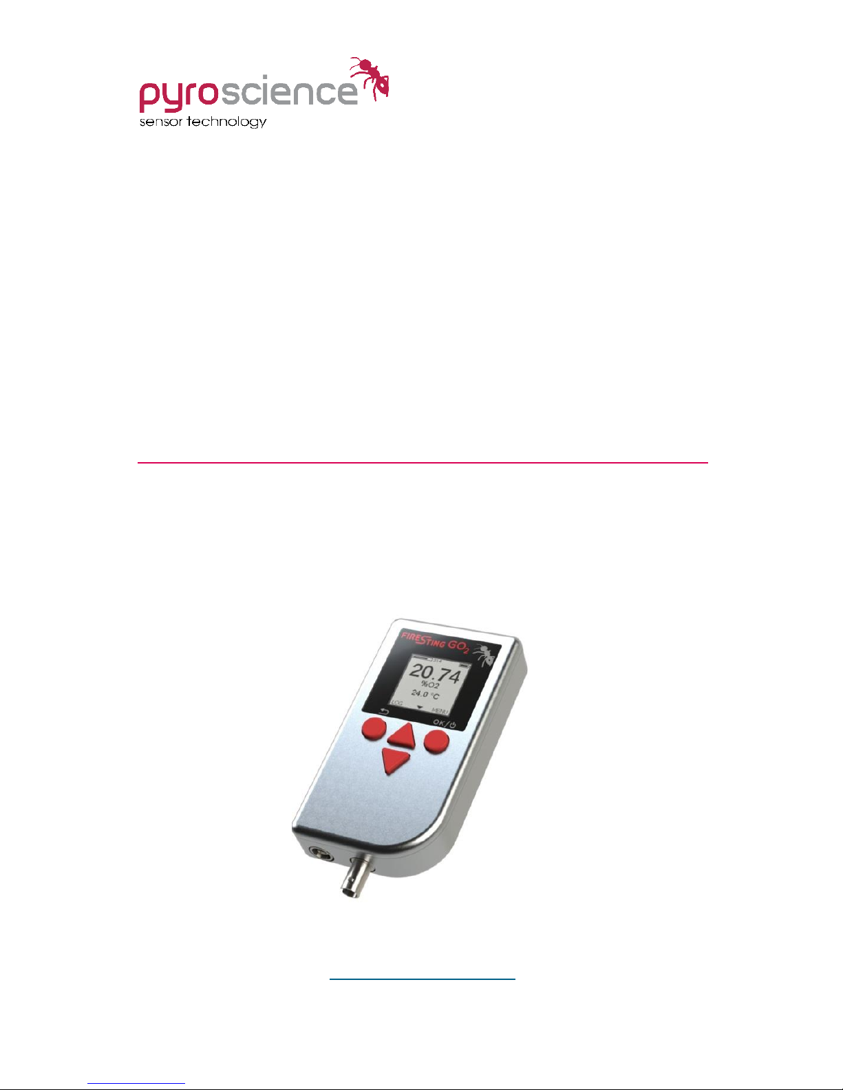
Pocket Oxygen Meter
FireStingGO2
MANUAL
www.pyroscience.com
Page 2

2
Document Version 1.21
Refers to FireStingGO2 Manager software version >1.0
The FireStingGO2 is manufactured by
PyroScience GmbH
Hubertusstr. 35
52064 Aachen
Germany
Phone +49 (0)241 518322-10
Fax +49 (0)241 518322-99
Email info@pyroscience.com
Internet www.pyroscience.com
Registered: Aachen HRB 17329, Germany
Page 3

3
TABLE OF CONTENT
1 INTRODUCTION ..................................................................... 6
2 SAFETY GUIDELINES .............................................................. 8
3 OVERVIEW FIRESTINGGO2 .................................................... 11
3.1 PORTS AND INTEGRATED SENSORS ............................................. 11
3.1.1 Micro USB Port .................................................................. 12
3.1.2 Oxygen Port ...................................................................... 12
3.1.3 Temperature Port .............................................................. 12
3.1.4 Internal Air Sensor ............................................................. 12
3.1.5 Power Button and Recharging the Battery .......................... 13
3.2 STAND CLAMP ......................................................................... 13
3.3 USER INTERFACE ...................................................................... 14
3.4 OPERATION MODES ................................................................. 15
3.4.1 Live Mode .......................................................................... 15
3.4.2 Menu Mode ....................................................................... 15
3.4.3 Logging Mode .................................................................... 15
3.4.4 Standby Mode ................................................................... 16
3.4.5 PC Mode ........................................................................... 16
3.5 STATUS LINE ........................................................................... 16
4 QUICK START ........................................................................ 18
4.1 GETTING STARTED ................................................................... 18
4.2 SETTINGS AND OPTIONS ADJUSTMENTS ...................................... 18
4.3 SENSOR CALIBRATION .............................................................. 18
4.4 LIVE MEASUREMENTS ............................................................... 19
4.5 DATA LOGGING ........................................................................ 19
4.6 DATA MANAGEMENT AND INSPECTION ......................................... 19
5 LIVE MODE ............................................................................ 20
5.1 TOP SCREEN ........................................................................... 20
5.2 SUB-SCREEN 1 ......................................................................... 20
5.3 SUB-SCREEN 2 ......................................................................... 20
5.4 SUB-SCREEN 3 ......................................................................... 20
Page 4

4
6 MENU MODE ......................................................................... 21
6.1 MAIN MENU ............................................................................ 21
6.2 SETTINGS MENU ...................................................................... 21
6.2.1 Sensor Code ...................................................................... 21
6.2.2 Medium ............................................................................. 22
6.2.3 Oxygen Units ..................................................................... 22
6.2.4 Temperature ...................................................................... 22
6.2.5 Salinity.............................................................................. 23
6.3 CALIBRATION MENU ................................................................. 23
6.3.1 Sensor Code ...................................................................... 24
6.3.2 Air Calibration ................................................................... 24
6.3.3 0% Calibration ................................................................... 27
6.4 OPTIONS MENU ....................................................................... 28
6.4.1 Adjust Time and Date ........................................................ 28
6.4.2 Temperature Offset ........................................................... 29
6.4.3 Device Info and Reset Device .............................................. 29
6.5 ADVANCED MENU .................................................................... 30
7 DATA LOGGING ..................................................................... 31
7.1 START LOGGING ...................................................................... 31
7.1.1 Manual Logging................................................................. 31
7.1.2 Continuous Logging ........................................................... 32
7.2 LOGGING MODE ...................................................................... 33
8 STANDBY MODE ................................................................... 35
9 PC MODE ............................................................................... 35
10 FIRESTINGGO2 MANAGER ..................................................... 36
10.1 SOFTWARE INSTALLATION ......................................................... 36
10.2 OPERATION WITHOUT CONNECTED DEVICE .................................. 36
10.3 OPERATION WITH CONNECTED DEVICE ........................................ 36
10.3.1 Live Graph Window ........................................................ 37
10.3.2 Settings ........................................................................ 40
10.3.3 Calibration .................................................................... 42
10.3.4 Air Calibration ............................................................... 43
10.3.5 0% Calibration .............................................................. 45
10.3.6 Data Logging ................................................................ 47
Page 5

5
10.3.7 Options ......................................................................... 50
10.4 LOG INSPECTOR AND FILE MANAGEMENT .................................... 52
10.4.1 File Management........................................................... 52
10.4.2 Log Inspector Window ................................................... 53
11 WARNINGS ........................................................................... 56
11.1 OXYGEN SENSOR WARNINGS ..................................................... 56
11.2 TEMPERATURE SENSOR WARNING .............................................. 57
12 CALIBRATION STANDARDS ................................................... 59
12.1 THE AIR CALIBRATION STANDARD .............................................. 59
12.1.1 Ambient Air ................................................................... 61
12.1.2 Water-Vapor Saturated Air ............................................ 61
12.1.3 Air Saturated Water ...................................................... 61
12.2 THE 0% STANDARD .................................................................. 62
12.2.1 Water Mixed with a Strong Reductant ............................ 62
12.2.2 Nitrogen Gas ................................................................. 63
13 APPENDIX ............................................................................. 64
13.1 SPECIFICATIONS OF THE FIRESTINGGO2 ...................................... 64
13.2 MEASURING PRINCIPLE ............................................................. 65
13.3 DEFINITION OF OXYGEN UNITS ................................................... 66
13.4 EXPLANATION OF THE SENSOR CODE .......................................... 68
Page 6
6
1 Introduction
The FireStingGO2 is a hand-held fiber-optic oxygen meter based
on the established FireSting technology featuring:
broad oxygen sensor portfolio (micro- and minisensors, robust
probes, sensor spots, flow-through cells, respiration vials)
sensors for the full and the trace oxygen range
measurements in water as well as in the gas phase
automatic temperature and pressure compensation
proven REDFLASH technology
with New Features:
integrated high contrast LCD display
integrated rechargeable battery and memory
extremely low power consumption for long-term logging
and Operation Modes:
stand-alone via intuitive LCD user interface
with Windows PC via USB
Page 7
7
The new pocket meter FireStingGO2 completes the portfolio of
different fiber-optic oxygen meters from PyroScience, comprising
PC-operated 1-, 2- or 4-channel FireStingO2 meters with a broad
oxygen sensor portfolio and the 1-channel
Piccolo2 meter for advanced applications
of contactless sensors, e.g. in microfluidics.
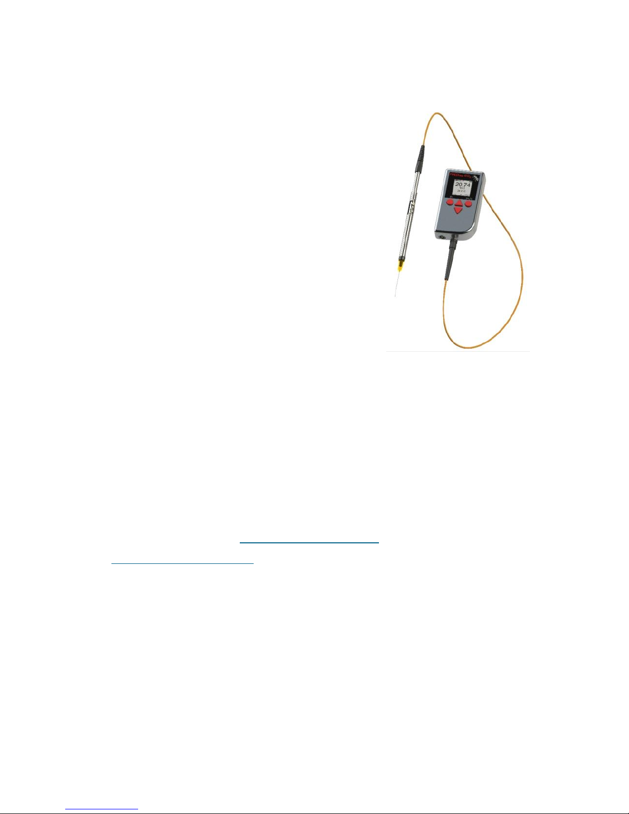
The FireStingGO2 has integrated memory
and battery and combines the established
FireStingO2 technology with stand-alone
operation and the ability of long-term
logging for >1 year. With this flexibility,
oxygen measurements can be performed
independent of a PC at different locations
using the broad range of fiber-optic
oxygen sensors from PyroScience.
The FireStingGO2 impresses by its compactness, functionality and
extremely low power consumption allowing for long-term logging
without the need of recharging. The handling of the FireStingGO2
is intuitive and all information concerning the connected and
internal sensors, measurement and logging parameters are
displayed on a high contrast LCD display.
More information concerning our product portfolio can be found
on our website at www.pyroscience.com or contact us under
info@pyroscience.com.
Your PyroScience Team
Page 8

8
2 Safety Guidelines
The FireStingGO2 is a laboratory instrument to be used with fiberoptic oxygen sensors (optodes) from PyroScience. In order to
guarantee an optimal performance of the FireStingGO2, please
follow these operation instructions and safety guidelines.
If any problems or damage evolve, please turn the instrument off
and disconnect it immediately. Mark this FireStingGO2 to prevent
any further use and consult PyroScience for repair or maintenance
service. The FireStingGO2 should not be manipulated or opened by
unauthorized persons, only by PyroScience or persons advised
directly from PyroScience.
Please note that opening the housing will void the warranty. There
are no serviceable parts inside the device.
The FireStingGO2 meter and the sensors should be kept and
stored outside the reach of children in a secure place under dry and
clean conditions at room temperature, avoiding moisture, dust,
corrosive conditions and heating of the instrument. This device
and the sensors are not intended for medical, military or other
safety relevant areas. They must not be used for applications in
humans; not for in vivo examination on humans, not for humandiagnostic or therapeutic purposes. The sensors must not be
brought in direct contact with foods intended for consumption by
humans.
The FireStingGO2 has an integrated lithium-ion battery, so please
follow the general safety instructions for their use. The
FireStingGO2 is not water-proof and should be used by qualified
personal only, following the operation instructions and safety
guidelines of this manual. Please follow the appropriate laws and
guidelines for safety like EEC directives for protective labor
legislation, national protective labor legislation, safety regulations
Page 9
9
for accident prevention and safety data-sheets from
manufacturers of chemicals used during measurements.
Calibration and application of the sensors, data acquisition, data
processing and data publication is on the user's authority.
When used in the field, the environmental conditions (like high
humidity, dust, exposure to direct solar radiation) may cause
damage or interference of the FireStingGO2, which is on the user's
authority.
Before using the oxygen meter FireStingGO2 and its sensors, read
carefully the available instructions and user manuals.
Page 10

10
In case of problems or damage, turn the instrument off,
disconnect and mark it to prevent any further use! Consult
PyroScience for advice! There are no serviceable parts inside the
device. Opening the housing will void the warranty!
The FireStingGO2 is not water-proof, is sensitive to corrosive
conditions and to changes in temperature causing
condensation. Avoid any condition (e.g. direct sun light) causing
a heating of the device above 50°C (122°F) or below 0°C (32°F).
Avoid elevated humidity causing condensing conditions. Please
follow the safety instructions for integrated lithium-ion
batteries.
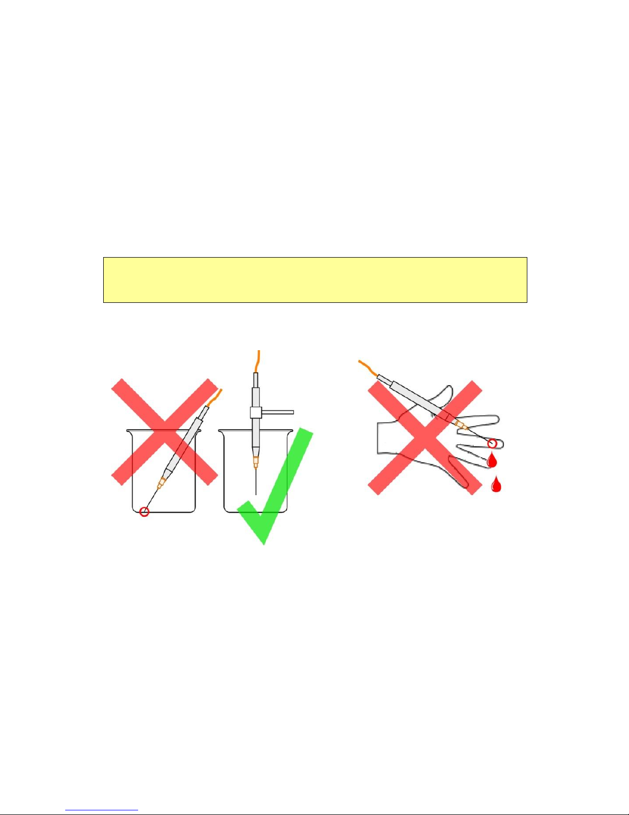
Handle the sensors with care especially after removal of the
protective cap! Prevent mechanical stress to the fragile sensing
tip and injuries with needle-type sensors! Avoid strong bending
of the fiber cable!
Calibration and application of the sensors, data acquisition,
treatment and publication is on the user’s authority!
The sensors and the oxygen meter FireStingGO2 are not
intended for medical, diagnostic, therapeutic, or military
purposes or any other safety-critical applications. The sensors
must not be used for applications in humans and must not be
brought in direct contact with foods intended for consumption
by humans.
The FireStingGO2 and sensors should be used in the laboratory
by qualified personnel only, following the user instructions and
the safety guidelines of the manual, as well as the appropriate
laws and guidelines for safety in the laboratory!
Keep the sensors and the oxygen meter FireStingGO2 out of
reach of children!
Page 11
11
3 Overview FireStingGO2
This chapter provides an overview about the principle components
and general operation procedures of the pocket oxygen meter
FireStingGO2.
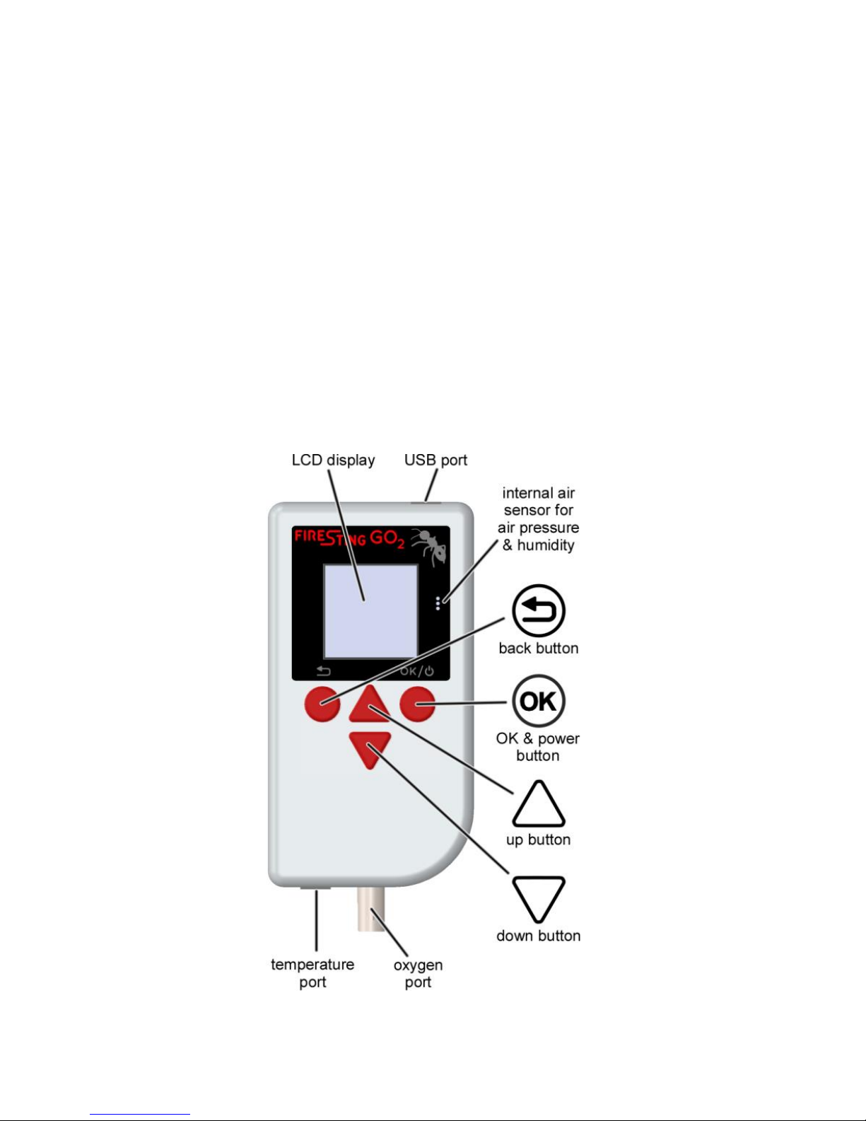
3.1 Ports and Integrated Sensors
The FireStingGO2 has three ports and one integrated sensor:
micro USB port for charging and communication
oxygen port for connecting a fiber-optic oxygen sensor
temperature port for connecting a temperature sensor
internal air sensor for pressure and relative humidity
Page 12

12
3.1.1 Micro USB Port
The micro USB port is used for recharging the integrated battery of
the FireStingGO2 (see below), as well as for data communication
with a PC in combination with the software "FireStingGO2
Manager". This software is especially needed for downloading and
inspecting logged data files from the FireStingGO2 device.
3.1.2 Oxygen Port
Fiber-optic oxygen sensors from PyroScience with ST-connectors
are connected to the oxygen port. Please refer to the website of
PyroScience concerning the broad range of available oxygen
sensor types. Remove the protective caps from the oxygen port as
well as from the ST-connector of the oxygen sensor. Then, insert
the ST-connector into the oxygen port and turn the bayonet
coupling gently clockwise until the plug is locked firmly.
3.1.3 Temperature Port
Temperature sensors (4-wire PT100-sensors with LEMO
connectors) are connected to the temperature port by simply
pushing the connector into the port. Please refer to the website of
PyroScience concerning available temperature sensors.
The temperature sensor can be used for automatic temperature
compensation of the oxygen measurement.
3.1.4 Internal Air Sensor
The internal air sensor measures the pressure and the relative
humidity of the ambient air. It is located behind the three little air
inlets located next to the right side of the display. These sensors
are needed for a precise determination of the actual oxygen level,
if the oxygen sensor is calibrated in ambient air. The pressure
sensor is additionally used for automatic pressure compensation of
the oxygen measurement.
Page 13
13
Keep the three little air inlets of the air sensor clean and dry in
order to assure a proper operation of this sensor. Do not cover
these air holes during the measurements.
3.1.5 Power Button and Recharging the Battery
The FireStingGO2 is switched on and off by pressing the right
button for ca. 1 second (OK button). Note, that the device cannot
be switched off, while the device is logging data or while it is in the
PC mode (see below).
If the device does not switch on by pressing the OK button, the
integrated battery needs to be recharged. For this, connect the
USB port of the FireStingGO2 to any standard micro USB charger
or to any available computer USB port (with the included USB
cable). Typically the battery is fully recharged within ca. 2 hours.
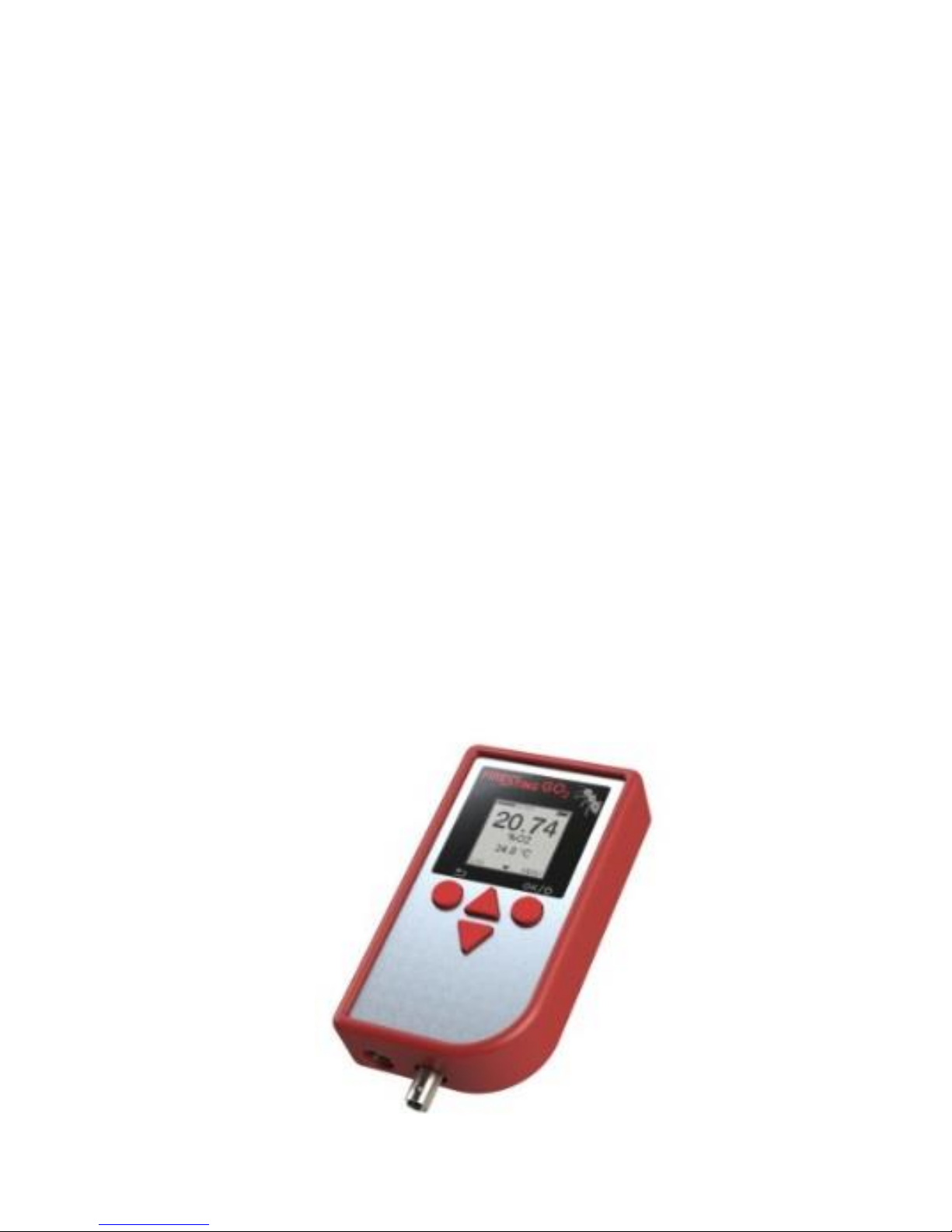
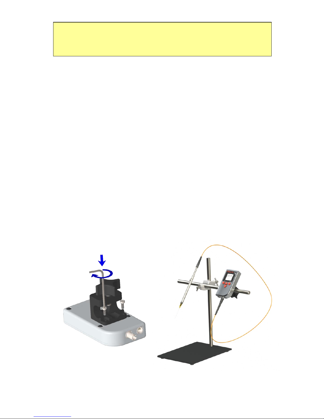
3.2 Stand Clamp
The FireStingGO2 can be optionally mounted on common lab
stands with the included stand clamp. For this, remove the red
silicone shell from the device and mount the stand clamp as shown
in the image.
Page 14
14
3.3 User Interface
The user interface of the FireStingGO2 consists of the display and
four buttons. The high-contrast display features ultra-low power
consumption. Therefore it is permanently activated without
significantly reducing the run-time of the rechargeable battery.
The four buttons allow for an intuitive stand-alone operation of the
FireStingGO2.
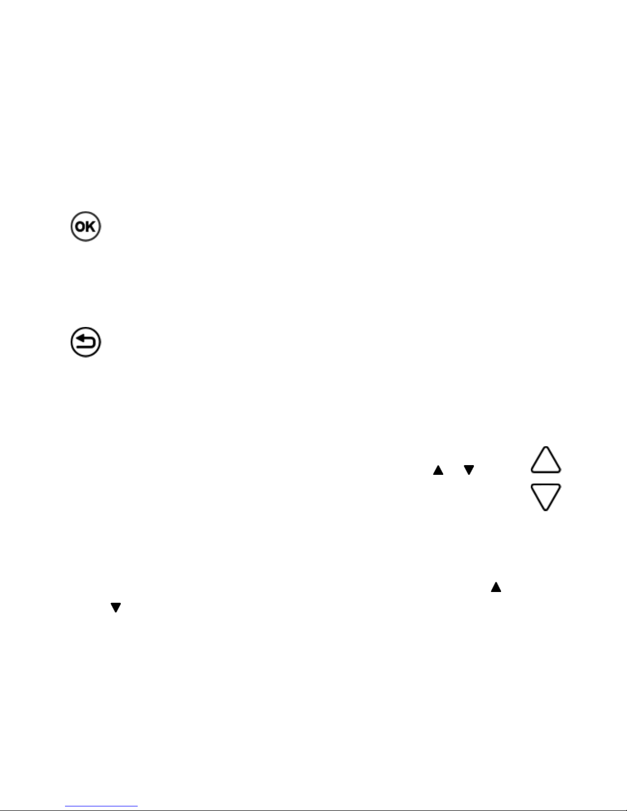
OK Button: If pressed for 1 second, the device is switched on or
off. If pressed shortly, then this button is generally used for
selecting an item or for confirming a setting. Alternatively, the
lower right corner of the display might show a context specific
function, e.g. MENU, START, NEXT, or SAMPLE.
Back Button: This button is generally used for "going back" e.g. in
menus, or for cancelling an operation. Alternatively, the lower left
corner of the display might show a context specific function, e.g.
CANCEL, BACK, or STOP. If pressed for 10 seconds, a hardware
reset of the device can be performed.
Up and Down Buttons: The context specific functionality of these
buttons is always indicated by small black triangles ( or ) in the
display. They are generally used for selecting items from menus or
dialog screens, but also for adjusting numerical values e.g. when
adjusting the sensor code or a temperature value in the settings.
Depending on the operation mode, there might be several „subscreens” available, which is indicated by small black triangles ( or
) appearing in the upper or lower line of the display. By pressing
the up or down buttons, the screen content will scroll up or down,
revealing the other sub-screens.
Page 15
15
3.4 Operation Modes
The user interface of the FireStingGO2 meter comprises five
different operation modes: Live Mode, Menu Mode, Logging
Mode, Standby Mode, and PC Mode.
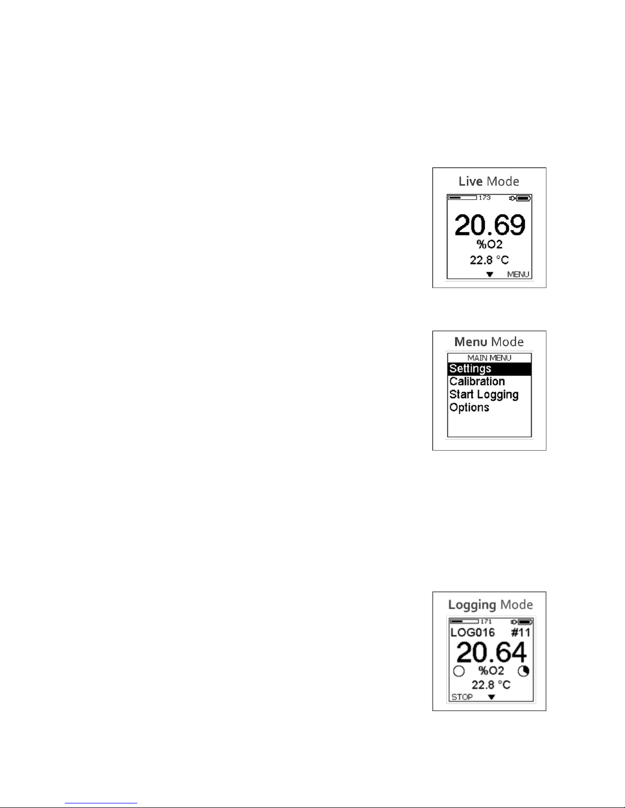
3.4.1 Live Mode
After switching on the FireStingGO2, the device
starts in the Live Mode. Here the device performs a
measurement every 2 seconds and shows the
results in altogether four sub-screens. The data are
not logged in this mode. For more details on the
Live mode refer to chapter 5.
3.4.2 Menu Mode
The Menu Mode can be opened in the Live Mode
by pressing the OK button. The menu is used for:
adjusting the settings
performing sensor calibration
starting data logging
accessing diverse options
After exiting the menu mode with the BACK button, the device
reverts to the Live Mode. For details on the menu mode refer to
chapter 6.
3.4.3 Logging Mode
The Logging Mode is started by selecting "Start
Logging" in the main menu and pressing the OK
button. In the logging mode the measured data
points (sensor readings) are saved in a log file
within the internal data memory of the device.
Altogether six sub-screens provide the user with
detailed information about the progress of the
data logging. If the Logging Mode is terminated, the device will
Page 16
16
revert to the Live Mode. For more details on the logging mode
refer to chapter 7.
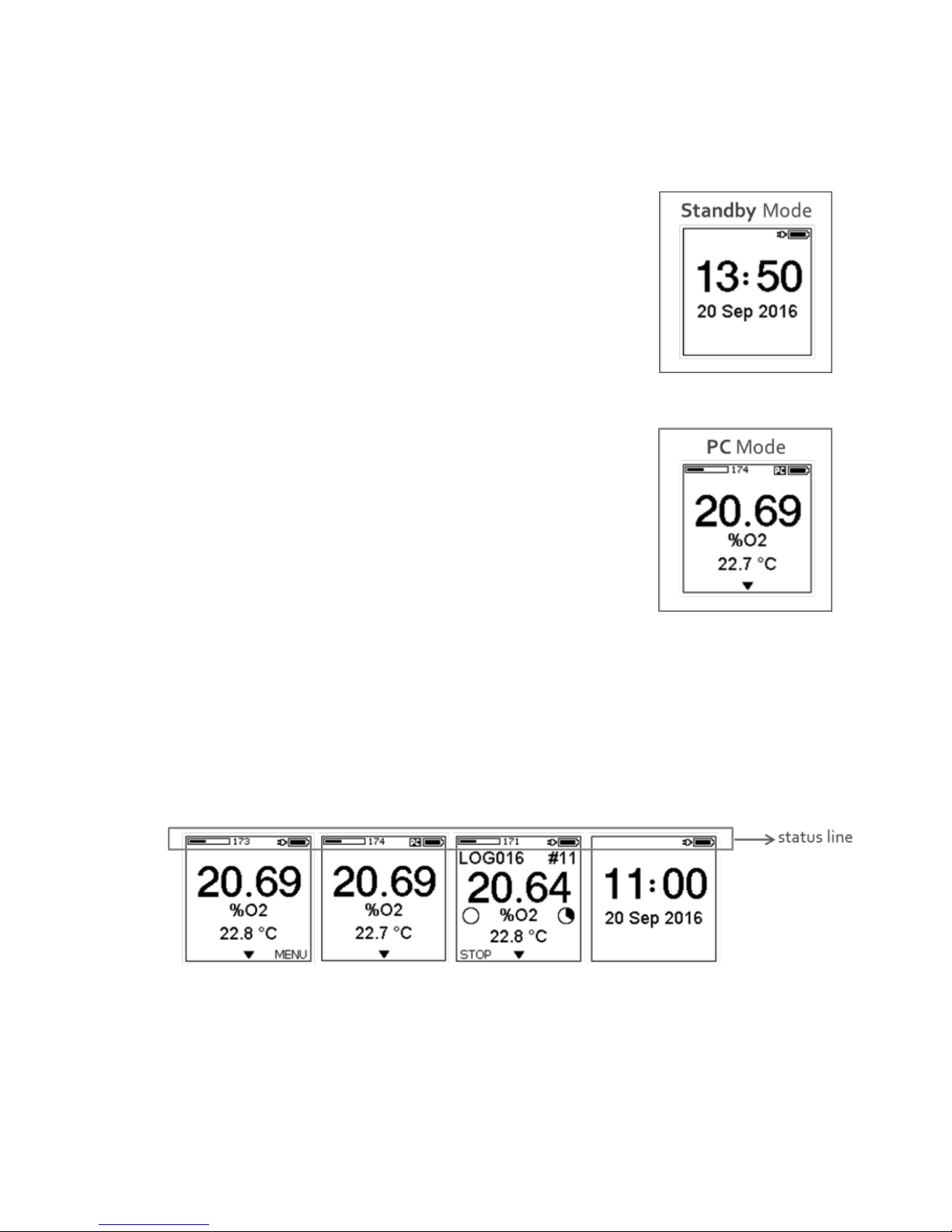
3.4.4 Standby Mode
The device automatically enters the Standby
Mode, if the user did not press any button within 5
minutes in the Live Mode. Here the measurements
are stopped to prolong the lifetime of the
connected oxygen sensor. For details on the
Standby Mode refer to chapter 8.
3.4.5 PC Mode
If the device is connected to a PC with the included
USB cable and the software FireStingGO2
Manager is started, the device enters the PC
Mode. This is indicated by the "PC" symbol in the
upper right corner of the display. Here the Menu
Mode is not accessible, only the sub-screens are
accessible with the UP and DOWN buttons. For more details on the
PC mode refer to chapter 9.
3.5 Status Line
In all modes except for the Menu Mode, the status line is shown in
the upper line of the display.
The battery symbol indicates the actual charge level of the internal
battery. The plug symbol indicates that an external power supply is
connected to the USB port. An arrow symbol between the plug and
the battery symbol indicates that charging is in progress. And the
PC symbol indicates that the device is in the PC Mode after the
Page 17

17
FireStingGO2 Manager software has been started on an external
computer (connected via the USB port).
In the Live, PC or Logging Mode, an additional bar graph and a
numerical value show the so-called "signal intensity". It provides
important information on the actual condition and remaining
lifetime of the connected oxygen sensor.
Potential warnings (Low Signal, No Signal, Too High, Bad Ref)
regarding problems with the oxygen sensor signal are displayed at
the position of the bar graph. For more details about trouble
shooting these warnings refer to chapter 11.
Do not continue with measurements if a warning is shown!
Page 18

18
4 Quick Start
4.1 Getting Started
Connect the oxygen sensor and optionally the temperature sensor
to the corresponding ports of the FireStingGO2 (chapter 3.1). Start
the FireStingGO2 meter by pressing the OK button for about 1 sec.
Check the battery charge level of the device in the status line
(chapter 3.5) and recharge the battery if necessary (chapter 3.1.5).
Select MENU with the OK button and first Adjust the local Time
and Date in the Options Menu (chapter 6.4.1)
4.2 Settings and Options Adjustments
For details refer to chapter 6.2.
Open the Settings Menu, enter the Sensor Code of the connected
oxygen sensor, select the sample Medium and choose your
preferred Oxygen Units. Adjust the sample Temperature used for
the temperature compensation of the oxygen measurements
(Sensor or Fixed). If applicable, adjust the sample Salinity.
4.3 Sensor Calibration
For details refer to chapter 6.3.
Open the Calibration Menu in the main menu and review if the
correct Sensor Code was adjusted. Prepare appropriate air and 0%
calibration standards. Open Calibrate Air and select the type of
temperature compensation used during the calibration: Sensor for
automatic temperature compensation with the connected
temperature sensor or Fixed with a defined and constant
calibration temperature (needs to be measured and controlled).
Then select the appropriate calibration medium equivalent to the
sample under investigation: Ambient Air for gas measurements
and Air Saturated Water for measurements in aqueous samples.
Insert the oxygen and temperature sensor into the air calibration
standard, wait for steady state and press SET AIR.
Page 19

19
After a successful air calibration, open Calibrate 0%, select the
type of temperature compensation used during the calibration
(Sensor or Fixed, see above), insert the oxygen and temperature
sensor into the 0% calibration standard, wait for steady state and
press SET 0%.
4.4 Live Measurements
Exit the menu by pressing the BACK button. Measurements are
performed now in the Live Mode every 2 seconds. Access the
different sub-screens with the UP and DOWN buttons, showing
the measurement results. Note, that the data are NOT logged in
the Live Mode.
4.5 Data logging
For details refer to chapter 7.
Open Start Logging in the Main Menu. Choose the appropriate
mode: Manual for manual logging, i.e. data points are logged each
time the OK button (SAMPLE) is pressed; Continuous for
automatized logging with adjustable Logging Interval and
Logging Duration. The logged data are displayed numerically and
graphically on several sub-screens. If the data logging is finished,
EXIT the Logging Mode with the BACK button.
4.6 Data management and inspection
For details refer to chapter 10.
Download and install the FireStingGO2 Manager software from
the PyroScience website to a Windows PC. Connect the
FireStingGO2 device with the included USB cable, and start the
software. Go to the File tab, select a log file and click on Download
& Inspect. This will download the log file from the device to the
PC, and show the logged data in the Log Inspector window.
Page 20
20
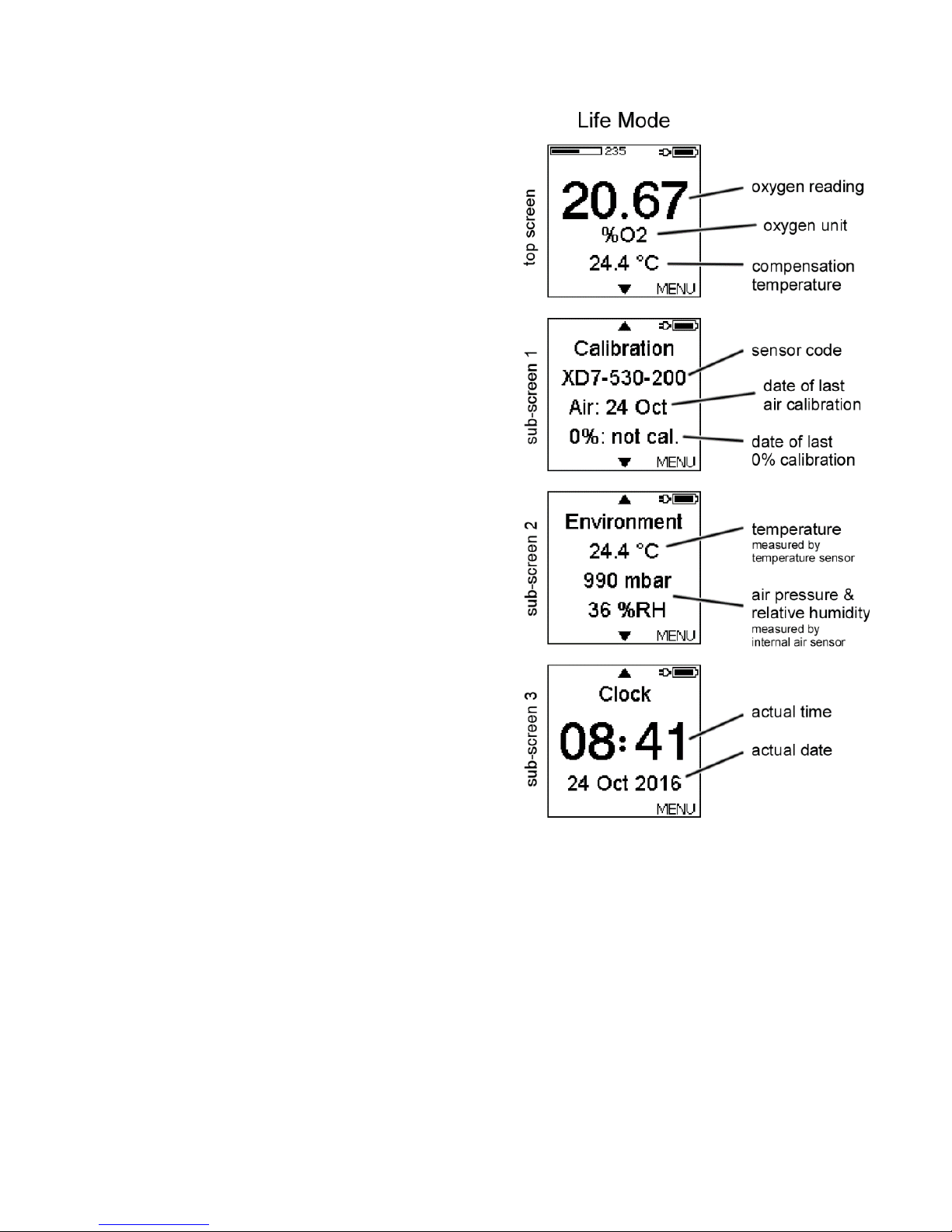
5 Live Mode
After power-up or after activation
from standby the FireStingGO2 is in
the Live Mode. Measurements are
performed every 2 seconds. The
different sub-screens can be
accessed with the UP and DOWN
buttons. Note, that the data are
NOT logged in the Live Mode.
5.1 Top Screen
Here, the current reading of the
connected oxygen sensor and the
selected oxygen unit (see chapter
6.2.3) is shown, as well as the
compensation temperature (sensor
or fixed, see chapter 6.2.4).
5.2 Sub-screen 1
Here the sensor code and the dates
of the last Calibrations are shown
(see chapter 6.3).
5.3 Sub-screen 2
This sub-screen shows details on the Environment, including the
readings of the temperature sensor (if connected) and of the
internal air sensor, including the air pressure (mbar) and relative
humidity (%RH) (see chapter 3.1.4).
5.4 Sub-screen 3
This sub-screen shows the Clock with the actual time and date.
Refer to chapter 6.4.1 how to set the clock.
Page 21
21
6 Menu Mode
The menu is entered by pressing the OK
button in the Live Mode, opening the main
menu.
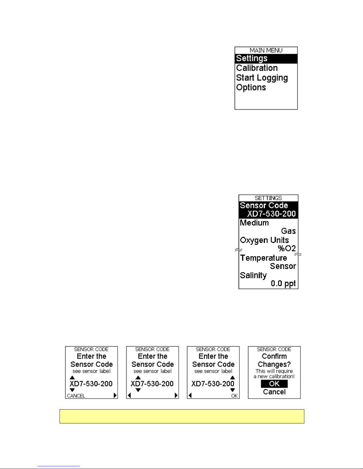
6.1 Main Menu
The main menu has four entries:
Settings: opens the Settings Menu (chapter 6.2)
Calibration: opens the Calibration Menu (chapter 6.3)
Start Logging: starts data logging (chapter 7)
Options: opens the Options Menu (chapter 6.4)
6.2 Settings Menu
The following settings have to be adjusted in
the Settings Menu.
6.2.1 Sensor Code
The Sensor Code written on the label
attached to the sensor or on the stickers/bags
of contactless sensors must be entered every
time a new oxygen sensor is connected. Enter
this sensor code by moving the cursor with the
BACK and OK buttons, and by adjusting each letter/number with
the UP and DOWN buttons. Press OK after the last number of the
sensor code has been adjusted. Confirm the changes by pressing
OK once more.
Changing the Sensor Code will discard the last calibration!
Page 22

22
6.2.2 Medium
Adjust here the medium Gas or Water of your sample.
6.2.3 Oxygen Units
Select here your preferred oxygen unit. Note, that the available
oxygen units depend on the chosen medium.
6.2.4 Temperature
Here the temperature of the sample has to be
adjusted. This is important in order to assure a
correct temperature compensation of the oxygen
measurement.
Select Sensor for enabling automatic temperature compensation
based on temperature measurements of the connected PT100
temperature sensor (chapter 3.1.3).
In order to ensure proper automatic temperature compensation,
position the temperature sensor in the sample, so that it measures
the same temperature as given around the oxygen sensor tip.
Page 23

23
If your sample is kept at a constant temperature,
then the automatic temperature compensation
can be deactivated by selecting Fixed. Now you
must enter the fixed temperature of your sample
used for the temperature compensation of the
oxygen measurement.
6.2.5 Salinity
The salinity of the sample only has to be
adjusted for measurements in saline samples
(e.g. seawater) using an oxygen concentration
unit, like µmol/L or mg/L.
6.3 Calibration Menu
After adjusting the sensor Settings (see chapter
6.2) and the local date and time in the Options
menu (see Adjust Time and Date in chapter
6.4.1), the connected oxygen sensor needs to be
calibrated before the measurements. Note, that
the top screen of the Live Mode shows the warning Not Calibrated
after a new Sensor Code has been entered. The calibration is
performed in the Calibration menu.
The oxygen sensor can be calibrated at two
calibration points:
(1) at ambient air or in air saturated water
(Calibrate Air), and
(2) at 0%O2, i.e. anoxic conditions (Calibrate
o%). For highest precision it is recommended to calibrate both
calibration points. However, if the expected measuring range is
close to one of the calibration points, then a 1-point calibration
might be sufficient. For example if the expected measuring range
in a liquid sample is 90-100% air sat., then a 1-point calibration at
air saturated water is for many applications sufficient. In this case
Page 24

24
the 0% calibration is taken from the factory calibration encoded in
the Sensor Code.
It is recommended to perform the calibration at conditions close to
the environmental conditions during the measurements, especially
regarding the temperature.
6.3.1 Sensor Code
For security the Calibration menu repeats the Sensor Code entry,
which is in fact identical to the Sensor Code entry given in the
Settings menu (chapter 6.2.1).
Before starting the calibration, double check that the correct
Sensor Code has been entered, as written on the label attached to
the sensor cable or on the bag/stickers of the sensor.
6.3.2 Air Calibration
Select Calibrate Air for starting an air calibration.
Then choose the type of temperature
compensation during the calibration:
a) For automatic temperature compensation of
the Calibration Temperature with the
temperature sensor connected to the
FireStingGO2 meter, select Sensor and confirm
with Ok.
b) A Fixed Calibration Temperature can be
entered with the UP and DOWN buttons after the
temperature of the calibration standard was
measured e.g. with a third-party temperature
meter.
NOTE: Ensure constant calibration conditions! If the calibration is
performed with a Fixed temperature, the temperature in the
calibration standard must be measured and kept constant!
Page 25

25
Now the Calibration Medium of the air calibration
standard needs to be defined as Ambient Air or
Water, depending on the environmental sample
under investigation.
It is recommended to perform the calibration in the same medium
as the one in the sample.
6.3.2.1 Calibration in Ambient Air
Calibration in ambient air is recommended, if the measurements
on the sample are done in the gas phase. During the calibration,
the atmospheric pressure and the relative humidity of the ambient
air will be read automatically from the internal air sensor (chapter
3.1.4). These readings are needed in order to calculate the actual
oxygen partial pressure in the ambient air.
Therefore, it is important that both the FireStingGO2 device and
the connected oxygen sensor are exposed to identical
environmental conditions.
Position the oxygen and the temperature sensor (if selected) close
to the air inlets on the right side of the FireStingGO2 display.
Ensure that the oxygen and temperature sensor are completely
dry; otherwise the relative humidity around the sensor will differ
from the measured humidity inside the FireStingGO2.
It is strongly recommended that the device and the sensors are
placed for >30 min. under constant environmental conditions
before the calibration is performed.
Page 26

26
Now Wait for Steady State until the sensor
readings are stable. Then press SET AIR and the
current oxygen sensor reading is taken for the air
calibration. After the completion of the air
calibration, the system returns to the Calibration
menu, showing now the date of the air calibration.
Note: SET AIR is only active if the oxygen sensor readings are
within the expected range for the connected sensor type. If SET
AIR is replaced by "out of range", check or replace the calibration
standard and the entered Sensor Code. Repeat the calibration.
6.3.2.2 Calibration is Air Saturated Water
Calibration in air saturated water is recommended, if the
measurements are done in aqueous samples. Refer to chapter 12.1
concerning preparation of appropriate calibration standards. This
calibration mode will automatically read the atmospheric pressure
from the internal air sensor inside the FireStingGO2. This reading is
needed to calculate the actual oxygen partial pressure in the
ambient air.
It is important that the sensor in the calibration standard is
exposed to the same atmospheric pressure as the FireStingGO2.
Now insert the oxygen sensor into the calibration
standard. If Sensor was selected for the
calibration temperature (see above), then insert
also the connected temperature sensor into the
calibration standard. Now Wait for Steady State
until the sensor readings are stable.
Note: If using retractable needle-type sensors (e.g. OXR50,
OXR230, OXR430), it is important that the sensor tip is extended!
Page 27

27
Then press SET AIR and the current oxygen sensor reading are
taken for the air calibration. After the completion of the air
calibration, the system returns to the Calibration menu, showing
now the date of the air calibration.
Note: SET AIR is only active if the oxygen sensor readings are
within the expected range for the connected sensor type. If SET
AIR is replaced by "out of range", check or replace the calibration
standard and the entered Sensor Code. Repeat the calibration.
6.3.3 0% Calibration
Refer to chapter 12.2 concerning preparation of appropriate 0%
calibration standards. Select Calibrate 0% for performing a 0%
calibration. Now choose the type of temperature compensation
during the 0% calibration:
a) For automatic temperature compensation of the Calibration
Temperature with the temperature sensor connected to the
FireStingGO2 meter, select Sensor and confirm with OK.
b) A Fixed Calibration Temperature can be
entered with the UP and DOWN buttons after the
temperature of the calibration standard was
measured e.g. with a third-party temperature
meter.
NOTE: Ensure constant calibration conditions! If the calibration is
performed with a Fixed temperature, the temperature in the
calibration standard must be measured and kept constant!
Now insert the oxygen sensor into the 0%
calibration standard. If Sensor was selected for
the calibration temperature, then insert also the
connected temperature sensor into the calibration
standard. Now Wait for Steady State until the
Page 28

28
sensor readings are stable.
Note: If using retractable needle-type sensors (e.g. OXR50,
OXR230, OXR430), it is important that the sensor tip is extended!
Then press SET 0% and the actual oxygen sensor
reading is taken for the 0% calibration. After the
completion of the 0% calibration, the system
returns to the Calibration Menu, showing now the
date of the 0% calibration.
Note: SET 0% is only active if the oxygen readings are within the
expected range for the connected sensor type. If SET 0% is
replaced by "out of range", check or replace the calibration
standard and repeat the calibration.
6.4 Options Menu
In the Options Menu several device and sensor
parameters can be adjusted. Furthermore, device
information can be retrieved and a reset of the
device can be performed.
6.4.1 Adjust Time and Date
Please note that it is recommended to Adjust the local Time and
Date before the calibration of the connected sensor (see chapter
6.3) and before logging is started (see chapter 7.1). Adjust them by
moving the cursor with the BACK and OK buttons, and by
adjusting each item with the UP and DOWN buttons.
Page 29

29
6.4.2 Temperature Offset
It is recommended to check the reading of the
PT100 temperature sensor periodically in a water
bath of known temperature. This is especially
important if a concentration unit (like µmol/L or
mg/L) was selected for the oxygen readings (see
chapter 6.2.3). A manual Temp. Offset can be entered for a 1-point
calibration of the temperature sensor (default: 0).
It is also possible to prepare a water-ice-mixture
giving 0°C, where at least 50 mm of the
temperature sensor tip is submerged. Wait for
steady state, read the measured temperature in
the top screen of the Live Mode, and enter it as a
negative Temperature Offset. After this, a new calibration of the
connected oxygen sensor must be performed (see chapter 6.3).
Changing the temperature offset will lead to a loss of the oxygen
sensor calibration.
6.4.3 Device Info and Reset Device
Information concerning the unique ID number of
the device, the number of saved log files, the used
space of the internal device memory (MB) and the
firmware version can be obtained by selecting
Device Info.
Reset Device can be used in order to reset all settings and
calibrations. Additionally it can be selected, whether to delete also
all log files on the internal device memory (Delete All) or to keep
them (Keep Data).
Page 30

30
Selecting Delete All will irrevocably delete all logged data on the
internal device memory!
6.5 Advanced Menu
The sub-menu Advanced includes advanced
features only for advanced users with special
instructions from PyroScience.
It is not recommended to change these advanced parameters
without the advice of PyroScience!
Page 31

31
7 Data Logging
Before starting data logging on the internal device memory,
ensure that the following steps have been performed:
Adjustment of Time and Date (see chapter 6.4.1)
Adjustment of the sensor Settings (see chapter 6.2)
Calibration of the connected oxygen sensor (see chapter 6.3)
7.1 Start Logging
In order to start the logging, select Start Logging
in the main menu (see chapter 6.1) and confirm
with OK. Here, a Manual (see chapter 7.1.1) and a
Continuous (see chapter 7.1.2) logging mode can
be selected.
7.1.1 Manual Logging
Select the logging mode Manual and press the OK
button. Now data points are logged each time the
OK button (SAMPLE) is pressed. However, the top
screen of the logging mode shows additionally live
readings with 2s sample period. These live
readings are NOT logged.
Please refer to chapter 7.2 for a description of the
information shown on the display during the
logging.
To exit the manual logging mode, press STOP. A
confirmation screen will appear. Press again STOP
for about 1 second, thereby returning to the Live
Mode.
Page 32

32
7.1.2 Continuous Logging
Select the logging mode Continuous and press
the OK button. In this mode data points are
periodically logged with adjustable sample
intervals and total logging duration.
Select the Logging Interval (1 s, 2 s, 5 s, 10 s, 30
s, 1 min, 2 min, 5 min, 10 min, 30 min, 1 hour, 2
hours or 4 hours) and press NEXT.
Select the Logging Duration (1 min, 2 min, 5
min, 10 min, 30 min, 1 hour, 2 hours, 6 hours, 12
hours, 1 day, 2 days, 4 days, 1 week, 2 weeks, 1
month, 3 months, 6 months, 1 year or Non-Stop)
and press NEXT.
Now the logging is started. Please refer to
chapter 7.2 for a description of the information
shown on the display during the logging.
In case of selecting a finite logging duration, the
logging is automatically finished at the end of the
logging duration. Now press EXIT for returning to
the Live Mode.
In case Non-Stop was selected for the Logging
Duration, the logging needs to be actively
stopped by pressing STOP. Also if a finite
Logging Duration was entered, the logging can be terminated at
any time by pressing STOP. A confirmation screen will appear.
Press then again STOP for about 1 second, thereby returning to
the Live Mode.
Page 33

33
7.2 Logging Mode
Each time a new logging is started, a new log file (LOGxxx) is
generated and numbered sequentially upwards (e.g. LOG001,
LOG002, LOG003 etc.). In this log
file, each recorded data point is
numbered sequentially upwards
(#xxx). The log file and the last
logged data point number are
underneath the status line in the
top screen of the Logging Mode.
The top screen shows further the
last logged readings from the
oxygen and the temperature
sensor. Please note, if Manual
Logging was selected, then
additionally live readings with 2s
sample period are shown here. But
data points are only logged each
time the OK button (SAMPLE) is
pressed.
Progress circles next to the oxygen
unit provide feedback when the
next data point will be logged (left
progress circle) and about the
remaining total logging time (right
progress circle).
In sub-screen 1 the last 100 logged
data points of the oxygen sensor
readings are displayed in a graph.
The last logged value is shown
additionally as a numerical value.
Page 34

34
In sub-screen 2 the last 100 data points of the compensation
temperature are displayed in a graph. The last logged
compensation temperature is shown additionally as numerical
value.
Sub-screen 3 shows information concerning the Environment,
including the readings of the temperature sensor (if connected), as
well as the air pressure (mbar) and relative humidity (%RH)
measured by the internal air sensor.
Sub-screen 4 includes all details of the actual log file, like the start
of the logging (Log Start with time and date), the actual log File
Size and Free device memory available. For the Continuous
logging mode, additional information concerning the adjusted
Logging Interval and Duration are shown, as well as the Time Left
for the remaining logging duration.
The last sub-screen 5 shows the clock with the actual device time
and date.
Page 35

35
8 Standby Mode
If no buttons are pressed in the Live Mode
within 5 min, the device enters the Standby
Mode. Here the device clock is shown in the
display. In the Standby Mode the
measurements are stopped in order to safe
lifetime of the connected oxygen sensor.
To return to the Live Mode, any button can
be pressed, opening the top screen of the Live Mode with the
actual readings of the connected sensors.
Note, that in the Logging Mode or in the PC Mode, the system will
not switch into the Standby Mode.
9 PC Mode
For managing the logged data saved on
the internal device memory, the
FireStingGO2 meter needs to be
connected to a Windows PC with the
included USB cable, on which the software
FireStingGO2 Manager was installed (see chapter 10.1).
After start of the software FireStingGO2 Manager on the PC, the
connected FireStingGO2 meter is in the PC Mode. This is indicated
in the status line of the device display.
In the PC Mode, only the UP and DOWN buttons are active for
scrolling between top and sub-screens of the Live Mode. Access to
the menu is blocked. However, now the FireStingGO2 meter can
be controlled completely by the FireStingGO2 Manager software
on the PC. It offers an extended functionality compared to the LCD
user interface, including log file download, log file deletion, and log
file inspection.
Page 36

36
10 FireStingGO2 Manager
The log files saved in the internal device memory of the
FireStingGO2 can be downloaded and inspected on a Windows PC
using the software FireStingGO2 Manager. Additionally, the
FireStingGO2 Manager software offers most features similar to the
ones given in the LCD user interface (adjusting settings,
performing calibrations, options).
10.1 Software Installation
IMPORTANT: Do not connect the FireStingGO2 to your PC before
the FireStingGO2 Manager software has been installed. The
software will install automatically the appropriate USB-drivers.
1. System requirements: PC with Windows 7 / 8 / 10 and min.
700 MB free disk space
2. Download the installer package of the FireStingGO2
Manager software from the PyroScience homepage:
www.pyroscience.com/downloads.html
3. Unzip and start the installer and follow the instructions.
10.2 Operation without Connected Device
The FireStingGO2 Manager software can be also used if no
FireStingGO2 device is connected to the PC. In this case only the
Log Inspector window can be opened, offering access onto the
already downloaded log files. Please refer to chapter 10.4 for more
details.
10.3 Operation with Connected Device
First connect the FireStingGO2 meter to the PC with the included
micro-USB cable, now start the software FireStingGO2 Manager.
The FireStingGO2 will switch into the PC mode, indicated by the
"PC" symbol in the upper right corner of the LCD display.
Page 37

37
The main window of the FireStingGO2 Manager offers 5 different
tabs (Settings, Calibration, Logging, File and Options) for
controlling the FireStingGO2 (more details below).
The battery symbol in the
top line indicates the battery
charging status of the
connected FireStingGO2
device. An animated battery
symbol indicates that the
charging is in progress. As
soon as the animation stops,
the charging is completed.
The buttons in the bottom
line open the Log Inspector
and the Live Graph window
(more details below).
The FireStingGO2 Manager allows full control on the device,
offering most features similar to the LCD user interface of the
FireStingGO2. Before starting live measurements or data logging,
following steps need to be done:
Get accustomed to the Live Graph window (chapter 10.3.1)
Adjust the sensor Settings (chapter 10.3.2)
Perform an oxygen sensor Calibration (chapter 10.3.3)
Perform live measurements or start Logging (chapter 10.3.6)
10.3.1 Live Graph Window
The Live Graph window is opened by clicking on the Live Graph
button in the main window. In the Live graph window, all current
sensor readings are displayed numerically in the Live Display.
Furthermore, different parameters can be displayed in the graph of
the Live Graph window.
Page 38

38
The Live Display shows numerical live readings of all sensors
comprising oxygen, compensation temperature, temperature (if a
temperature sensor is connected), and the readings of the internal
air sensor (air pressure, relative humidity). For
more details refer to chapter 5.
Above the oxygen value, an additional bar
graph and a numerical value show the socalled "signal intensity". It provides important
information on the actual condition and
remaining lifetime of the connected oxygen
sensor. Potential warnings (see chapter 11)
are displayed above the bar graph.
If data logging is not active, the warning "Data are NOT logged!"
is shown above the graph. Data displayed in the Live Graph are
then NOT saved to a log file!
Page 39

39
If data logging is active, the Log Name, the Start time of the
logging and the Comment entered before the start of the logging,
are displayed above the graph.
As default shown in the Live Graph are the
current readings for oxygen and for the
compensation temperature (Comp. Temp.).
To show or hide other parameters in the Live
Graph, click on the small rectangular buttons
next to the respective parameters.
The color and appearance of each graph can be changed by
clicking on the color-control next to the respective parameter,
opening a pop-up menu. With Common Plots, Color, Line Style,
Line Width, Interpolation, and Point Style the chart appearance
can be changed.
The visible time frame of the live graph can be moved with the
scroll bar below the graph. With the button Move, the user has the
possibility to click onto the chart and move the whole area while
keeping the mouse button pressed. To zoom into a certain part of
the graph, click on the button Zoom and select a rectangular area
with the pressed mouse button.
To select the unit of the x-axis Time, click on the button Seconds
(s) (default) and select the appropriate unit as Seconds (s),
Minutes (min), Hours (h), Relative Time (HH:MM:SS), Absolute
Time (HH:MM:SS) or Absolute Time & Date. The activated
Autoscroll button ensures that the latest data points are always
within the visible range of the live graph. Switching off the
Page 40

40
Autoscroll button allows inspection of older data with the scroll
bar.
Smart Autoscale Y will trigger an autoscale of the y axes with
"smart" ranges for better readability. Autoscale X & Y performs a
classical autoscale of all x and y axes. Click on Adjust Scale in order
to adjust all scales manually by entering the maximum, minimum,
and the increment (tag spacing) for all x and y axes.
The graph can be cleared with the button Clear Graph. This will
not affect the saved data in the log file.
10.3.2 Settings
Open the Settings tab to
adjust the sensor settings.
Here, the Sensor Code, the
Medium of the sample, the
Oxygen Units of the
measurements and the
environmental conditions,
including the Temperature
Compensation and, if
applicable, the Salinity
(psu) of the sample under
investigation have to be
adjusted.
The Settings can only be adjusted if data logging is not active.
Enter the Sensor Code written on
the label attached to the sensor
cable or on the bag/stickers of the
oxygen sensor by clicking on the field
Sensor Code, therewith opening the
Sensor Code window. Adjust each
Page 41

41
position of the respective sensor code and click on OK.
Changing the Sensor Code, e.g. in case of connecting a new
sensor, requires a new calibration of the oxygen sensor!
Then define the medium of your sample by clicking in the field
Medium and selecting Gas or Water, depending on the
environmental sample under investigation. Then select the
appropriate Oxygen Units for the measurements. Please note that
different oxygen units can be selected for the Medium Gas (%O2,
hPa, Torr, dphi) and Water (%air saturation, mL/L, µmol/L, mg/L,
µg/L, hPa, Torr, dphi).
Now the Environmental Conditions in the sample need to be
defined. The possible modes of Temperature Compensation
during the oxygen measurements include temperature
measurements in the sample with the connected PT100
temperature Sensor. Alternatively, the measurements can be
performed with a fixed
sample temperature. In
this case the
temperature needs to be
measured in the sample
and entered as Fixed
Temperature (°C).
IMPORTANT: For measurements with a Fixed temperature, the
temperature in the sample must be measured and kept constant
during the entire measurement!
For measurements in saline samples (e.g. seawater) using an
oxygen concentration unit like µmol/L or mg/L, the salinity of the
sample must be measured and entered in the field Salinity (psu).
Page 42

42
For measurements in gas samples this value has no relevance (and
is not shown).
10.3.3 Calibration
The oxygen sensor is calibrated in the Calibration
tab. If a sensor is not yet calibrated, a warning
Not Calibrated replaces the oxygen unit in the
live graph.
The oxygen sensor can be calibrated at two
calibration points:
(1) in ambient air or in air saturated water (Calibrate Air), and/or
(2) at 0%O2, i.e. in an anoxic calibration standard (Calibrate o%).
For highest precision it is
recommended to calibrate
both calibration points.
However, if the expected
measuring range is close to
one of the calibration
points, then a 1-point
calibration might be
sufficient. For example if
the expected measuring
range in a liquid sample is
95-100% air sat., then a 1point calibration at air
saturated water is typically
sufficient. In this case the 0% calibration is taken from the factory
calibration encoded in the Sensor Code.
It is recommended to perform the calibration at conditions close to
the environmental conditions during the measurements.
For security the Calibration tab repeats the Sensor Code entry,
which is in fact identical to the Sensor Code entry given in the
Page 43
43
Settings tab (chapter 10.3.2). Double check the entered Sensor
Code is identical to the one written on the label attached to the
sensor cable or on the bag/stickers of the sensor.
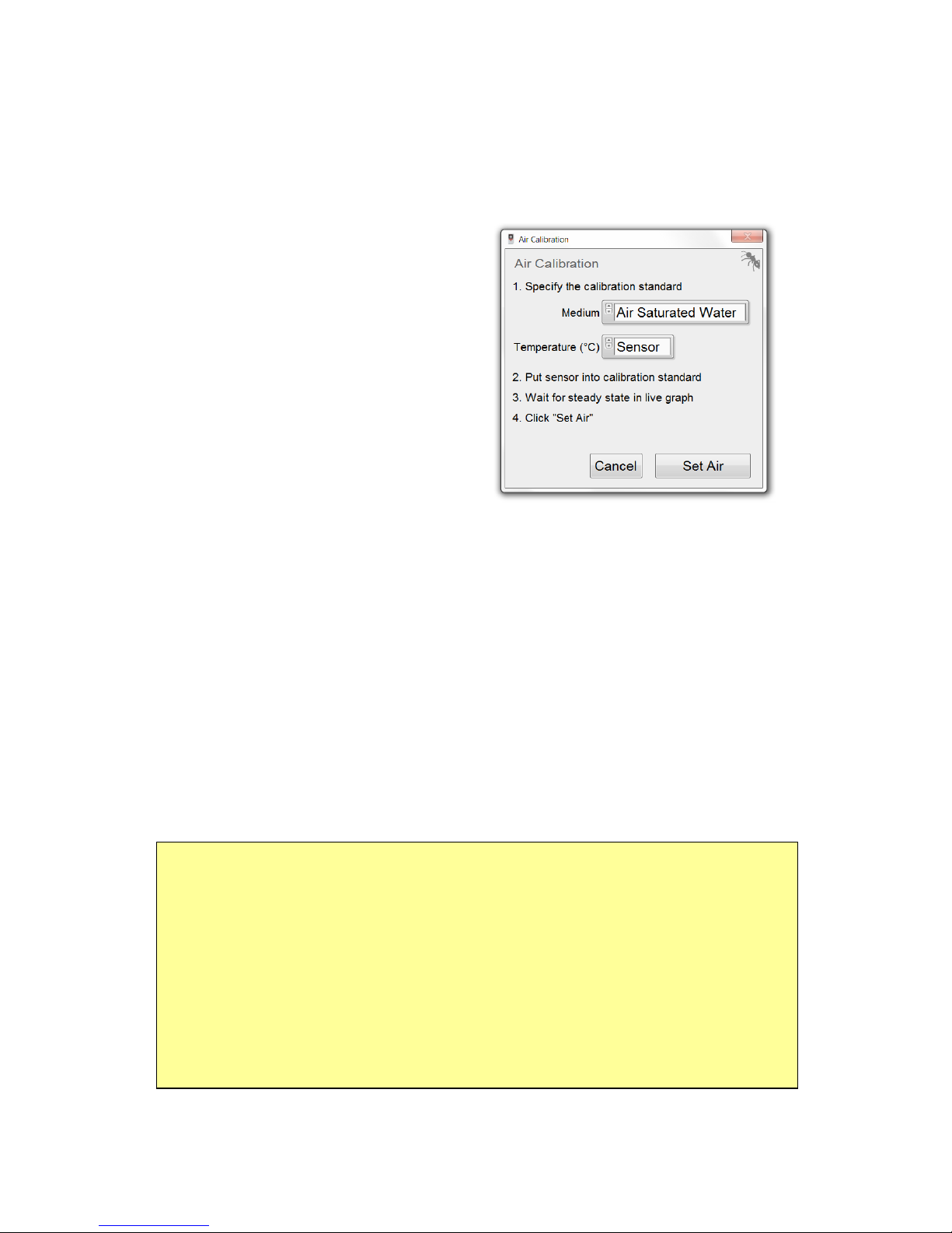
10.3.4 Air Calibration
Click on the button Calibrate Air
to open the Air Calibration
window. This will also
automatically open the Live
Graph window (see 10.3.1).
(1) Choose Calibration Medium.
Specify the Medium of the
calibration standard. If the
measurements will be done in
the gas phase, it is advised to choose Ambient Air and to continue
with step (2A). If the measurements will be done in aqueous
samples, it is advised to choose Air Saturated Water and to
continue with step (2B).
(2A) Calibration in Ambient Air. Ambient air serves as a simple
standard (ca. 20.95%O2 in dry air). In order to determine the
precise oxygen partial pressure in ambient air, the atmospheric
pressure and the relative humidity will be read automatically from
the internal air sensor (chapter 3.1.4).
Ensure that both the FireStingGO2 device and the connected
sensors are exposed to identical environmental conditions.
Position the sensor tips in close proximity to the FireStingGO2
device.
Ensure that the oxygen and the temperature sensor are completely
dry; otherwise the relative humidity around the sensors will differ
from the measured humidity inside the FireStingGO2.
Page 44

44
It is strongly recommended that the device and the sensors are
placed for >30 min. under constant environmental conditions
before the calibration is performed.
(2B) Calibration in Air Saturated Water. Please refer to chapter
12.1 concerning preparation of an appropriate calibration standard.
Note that this calibration mode will automatically read the
atmospheric pressure from the internal air sensor inside the
FireStingGO2, which is needed for calibration. Therefore, the
calibration standard must be exposed to the same atmospheric
pressure as the FireStingGO2 device.
Insert the sensors for oxygen and temperature (if selected for
automatic temperature compensation) into the calibration
standard. It is important that the sensor in the calibration standard
is exposed to the same atmospheric pressure as the FireStingGO2.
Note: If using retractable needle-type oxygen sensors (e.g. OXR50,
OXR230, OXR430), it is important that the sensor tip is extended
when the calibration value is taken.
(3) Temperature Compensation. Select now the mode of
temperature compensation used during air calibration by clicking
on Temperature (°C). For automatic temperature compensation
with the temperature sensor connected to the FireStingGO2
device, select Sensor.
Alternatively, a Fixed calibration temperature can be entered after
the temperature of the calibration standard was measured e.g.
with a third-party temperature meter.
NOTE: Ensure constant calibration conditions! If the calibration is
performed with a Fixed temperature, the temperature in the
calibration standard must be measured and kept constant!
Page 45

45
(4) Wait for Steady State until the oxygen and temperature
readings are stable by observing the Live Graph window (see
10.3.1).
(5) Calibrate by clicking on Set Air. The current oxygen sensor
reading is taken for the air calibration and the date of the last
calibration is updated in the
Calibration tab.
Note: A calibration is only possible if the oxygen sensor readings
are within the expected range for the connected sensor type. If the
warning "Calibration out of expected range" is shown, the
calibration is discarded. Check or replace the calibration standard
and perform a new calibration.
10.3.5 0% Calibration
Refer to chapter 12.2 how to
prepare an appropriate 0%
calibration standard. Click on
Calibrate 0% in the Calibration
tab. This will open the 0%
Calibration window and the
Live Graph window (see
10.3.1).
(1) Temperature Compensation. Select now the mode of
temperature compensation used during 0% calibration by clicking
on Temperature (°C). For automatic temperature compensation
with the PT100 temperature sensor connected to the FireStingGO2
device, select Sensor.
Alternatively, a Fixed calibration temperature can be entered after
the temperature of the calibration standard was measured with a
third-party temperature meter.
Page 46

46
NOTE: Ensure constant calibration conditions! If the calibration is
performed with Fixed temperature, the temperature in the
calibration standard must be measured and kept constant!
(2) Put Sensors into Calibration Standard. Now insert the oxygen
sensor into the calibration standard. If Sensor was selected for the
calibration temperature (see above), then insert also the
connected temperature sensor into the calibration standard.
Note: If using retractable needle-type sensors (e.g. OXR50,
OXR230, OXR430), it is important that the sensor tip is extended
when the calibration value is taken.
(3) Wait for Steady State until the oxygen and the temperature
readings are stable by observing the Live Graph window (see
10.3.1).
(4) Calibrate by clicking on Set 0%. The current oxygen sensor
reading is taken for the 0% calibration and the date of the last
calibration is updated in the Calibration tab.
Note: A calibration is only possible if the oxygen sensor readings
are within the expected range for the connected sensor type. If the
warning "Calibration out of expected range" is shown, the
calibration is discarded. Check or replace the calibration standard
and perform a new calibration.
Page 47

47
10.3.6 Data Logging
Before starting data Logging, adjust the sensor Settings and
complete a sensor Calibration. To deploy the device after logging
has been started, please ensure that the FireStingGO2 Manager
software is closed before the device is disconnected.
Even if the FireStingGO2 is
operated with the FireStingGO2
Manager software, the logged
data are always saved within
the device memory of the
FireStingGO2. After finalization
of the logging, the log file can
be downloaded from the device
to the PC. This feature ensures
that the device can be
disconnected without problems
from the PC, even when logging
is active. A typical scenario is
that the device is configured and calibrated with the FireStingGO2
Manager, then logging is started and the device is disconnected
and deployed at the measurement location. Later when the
measurements are completed, the device is again connected to the
PC, and the logged data are downloaded and inspected. The
following steps must be done for data logging:
(1) Device Time. Data logging is
managed in the Logging tab of the
main window. First check the current
device time (i.e. the time of the internal
clock in the FireStingGO2) shown in this
tab. The time and date information for
the logged data are always related to
this device time (and not the PC time).
Page 48

48
If it is incorrect, click on Set
Device Time. This opens a
window for adjusting the device
time. Clicking on Synchronize
will set it to the PC Time.
Alternatively the time and date
can be adjusted manually. For
this, edit the time and date
below "Set Manually", and click
on Set.
(2) Logging Mode. Select the
Logging Mode as Manual or
Continuous. In the Manual logging mode the user has to trigger
the logging for each single data point. Go on with step (5). In the
Continuous logging mode the device will automatically log data
points in defined time intervals.
(3) Logging Interval (only for continuous mode). Select the
sampling Interval used during the logging as 1 s, 2 s, 5 s, 10 s, 30 s,
1 min, 2 min, 5 min, 10 min, 30 min, 1 h, 2 h or 4 h. It is advised to
choose this interval not unnecessarily too small, in order to
increase the battery run time, and to avoid too large log files.
(4) Logging Duration (only for continuous mode). The logging
Duration can be set to 1 min, 2 min, 5 min, 10 min, 30 min, 1 h, 2 h,
6 h, 12 h, 1 d, 2 d, 4 d, 1 week, 2 weeks, 1 month, 3 months, 6
months, 1 year or to Non-Stop.
(5) Comment. Enter optionally a Comment, which will be saved in
the header of the log file as soon the logging is started.
(6) Start Logging. Click now on Start which opens a separate
window Name Logging File. This window displays the log files
saved in the device memory, including Date and Time, the Log
Name, the Size (in kB), as well as the total number of Log Files and
Page 49

49
the used Device Memory (MB).
The software automatically
generates a new log file with the
default name „LOGxxx”
numbered sequentially upwards
(e.g. LOG001, LOG002, LOG003,
etc.). If wished, this default file
name can be changed by the user
in the field Please name your log
file (8 characters possible).
After clicking on Start Logging,
the Live Graph window opens
(see chapter 10.3.1) and the tabs Settings, Calibration and Options
in the main window are de-activated and cannot be changed
during the logging. The Log Name, the Start time of the logging
and the optional Comment are now displayed in the bottom line of
the Logging tab.
(6a) Manual Logging Mode. Logging of a single data point is now
done manually by clicking on the button Sample. A single data
point is then saved to the log file
and added to the graph in the
Live Graph window. The
FireStingGO2 performs in this
logging mode additional
intermediate measurements with
2 seconds interval which are
displayed only in the Live Display
(see 10.3.1) but NOT in the Live
Graph. These intermediate
measurements are NOT saved to
the log file.
Page 50

50
(6b) Continuous Logging Mode. Data logging is now done
automatically with the chosen logging Interval and logging
Duration. The logged data are displayed in the Live Graph
window.
(7) Finish Logging. Data
logging can be always stopped
by pressing the button Stop.
Additionally the logging is
automatically finished in the
continuous Logging Mode, as
soon the total logging Duration
has elapsed. After data logging
is finished, the respective log file
is automatically downloaded. As
soon the download is finished,
the logged data will be shown in
the Log Inspector (see chapter
10.4.1).
10.3.7 Options
The Options tab contains
information concerning the
FireStingGO2 Manager (soft-
ware version) and the
connected FireStingGO2 device
(Device ID, firmware version).
The Device ID is a unique
identification number specific
for each single device. The
header of each log file contains
this Device ID. This way each
log file can be unequivocally assigned to a specific FireStingGO2
device. The following subsections describe the other feature within
the Options tab.
Page 51

51
10.3.7.1 Temperature Sensor Offset
It is recommended to check the reading of the temperature sensor
periodically in a water bath of known temperature at steady state.
This is especially important if a concentration unit (like µmol/L or
mg/L) was selected for the oxygen readings (see chapter 6.2.3).
A manual Temp. Offset can be entered for a 1-point calibration of
the temperature sensor (default: 0).
Changing the temperature offset requires new calibration of the
connected oxygen sensor afterwards.
For a detailed description how to determine the temperature
offset of the sensor, please refer to chapter 6.4.2.
10.3.7.2 Flash Logo
The button Flash Logo causes a short flashing (ca. 1 sec) of the
PyroScience logo on the display of the FireStingGO2 meter. The
flashing of the logo can help to assign a specific FireStingGO2
Manager software window to the corresponding FireStingGO2
meter, if more than one device is connected.
10.3.7.3 Advanced Mode
The Advanced Mode comprises advanced features only for
advanced users with special instructions from PyroScience. It is
NOT recommended to change these advanced parameters
without the advice of PyroScience!
By activating the Advanced Mode, a new small tab is displayed in
the main window, which enables direct access to low level
parameters only relevant for advanced applications. Furthermore
the Advanced Mode enables to monitor the fundamental raw data
of the oxygen measurement, which comprises the phase shift dphi
(see chapter 13.3) and the signal intensity in the Live Graph and the
Log Inspector.
Page 52

52
10.4 Log Inspector and File Management
The actual data logging is always done on the internal device
memory of the FireStingGO2. The File tab in the main window
provides a list of all log files currently saved in the device memory.
First after a log file has been downloaded, it can be inspected
within a separate window called Log Inspector, which contains a
list of all downloaded log files currently saved on the PC hard disk.
For opening this window manually click on the Log Inspector
button in the main window.
10.4.1 File Management
For the management of the log
files saved in the device
memory, click on the tab File in
the main window. Here, the
Log Files in the Device
Memory of the connected
FireStingGO2 meter are shown
in a file list with details about
the Date and Time, the Log
Name, the Size (kB) and the
Download status (%) of the log
files. Clicking on the header of a
column will sort the list alphabetically for this respective column.
Repeated clicking on the same column header will reverse the
sorting order.
10.4.1.1 Downloading Log Files from the Device to the PC
To download one or several log files from the device to the PC, the
respective log files must be selected by clicking on them in the File
tab. Multiple log files can be selected by pressing additionally the
CTRL or SHIFT buttons on the PC keypad. With the button
Download, the selected log files are then downloaded to an
automatically generated folder PyroScience Log Files/
Page 53

53
FireStingGO2 Device ID xxx within the default user
document folder on the Windows PC. It is
recommended to keep this default folder unchanged.
During downloading, the progress of the download is
indicated and can be stopped by clicking on the red
stop button.
Note, that when an actual data logging is finished while the device
is operated with the FireStingGO2 Manager, then the download of
this actual log file is automatically triggered.
The downloaded data files can be now inspected in the Log
Inspector window (see chapter 10.4.2).
The button Download & Inspect has essentially the same
functionality as the Download button. The only difference is, that
only a single data file can be downloaded, and that the Log
Inspector automatically opens, as soon the download is finished.
10.4.1.2 Deleting Log Files from the Device Memory
In order to delete log files from the
device memory, select one or multiple
log files in the File tab list and click on
Delete from Device. Multiple log files
can be selected by pressing additionally
the CTRL or SHIFT buttons on the PC keypad. Please note that the
selected files are permanently deleted from the internal memory
of the device and cannot be retrieved anymore.
NOTE: Deleted log files are not saved in a recycle bin! Do not
forget to download the log files to the PC before deleting them
from the device memory.
10.4.2 Log Inspector Window
The Log Inspector window is opened manually by clicking on the
Log Inspector button in the main window. Here only the log files
Page 54

54
are listed, which have been downloaded from the device to the
Download Folder on the PC. The left section of the Log Inspector
window lists the downloaded log files in a table with relevant
details (Date and Time, the Log Name and the file Size (kB)).
Above this list, the file path of the default download folder on the
PC is indicated.
Note: The default location of the download folder contains the
Device ID (see chapter 10.3.7), which ensures that the downloaded
files can be unequivocally assigned to a specific FireStingGO2
device. It is advised not to change this download location,
especially if several devices are operated in parallel. Advanced
users might choose a custom download folder by clicking on
Change.
The button Explore opens the current download folder within the
Windows operation system. This feature is not needed for
standard procedures. But it allows for advanced users direct access
to the log files (tab separated text files).
Page 55

55
IMPORTANT if using the button Explore: It is strongly
recommended not to change the log file names or their content
within this download folder, in order to assure a smooth operation
with the FireStingGO2 Manager. It is recommended first to copy
log files from this folder to another location, before processing
them.
Alternatively to the Explore button, the Save as… button can be
used to choose a custom file name and location (e.g. on the
desktop). This will save a copy of the respective log file (tab
separated text file).
In order to delete log files within the download folder on the PC,
select one or multiple log files in the file list and click on Delete
from PC. Multiple log files can be selected by pressing additionally
the CTRL or SHIFT buttons on the PC keypad. Please note that the
selected files are permanently deleted from the PC and cannot be
retrieved anymore.
By selecting a log file in the Download Folder list, the logged data
for this specific log file are automatically shown in the graph visible
in the right section of the Log Inspector window. The header of
the graph includes the Log Name, the Start time of the logging
and the Comment, if entered before the start of the logging.
Please refer to chapter 10.3.1 for the diverse features available for
manipulating the graph appearance.
The actual log file content can be optionally displayed in a text
table by clicking on Data Table. Or it can be directly exported to
Microsoft Excel by clicking on Open in Excel (only possible if
Microsoft Excel is installed on the PC).
To copy a screenshot of the current graph to the Windows
clipboard, click on Copy Graph to Clipboard. Now this screenshot
can be pasted (CTRL+V) to many other Windows programs (e.g.
Microsoft Word or Excel).
Page 56

56
11 Warnings
The following warnings are potentially displayed in the status line
of the LCD screen of the FireStingGO2 (see chapter 3.5). If the
FireStingGO2 is operated with the FireStingGO2 Manager
software, the warnings are also shown in the Live Graph window
(chapter 10.3.1).
11.1 Oxygen Sensor Warnings
A reasonable oxygen sensor shows signal intensities well above 50
(typically 50-500)1. If the signal intensity drops below 50, the
warning Low Signal is shown, indicating that the sensor might get
degraded soon. But for contactless sensors it might indicate that
the distance between the optical fiber and the sensor spot is too
large. In order to increase the signal intensity, advanced users
might increase the intensity of the excitation light (red light flashes
coming out of the oxygen port) by changing the second letter of
the Sensor Code (details in 13.4).
Low Signal: Measurements are still possible with potentially
decreased performance.
If no oxygen sensor is connected or if the sensor is broken or
damaged, the warning No Signal will be shown in the status line /
Live Display.
No Signal: Please check whether the sensor cable is connected or
replace the sensor, the tip might be broken / bleached.
The Warning Too High indicates that there might be too much
ambient light on the sensor tip or on the sensor spot. Or there
1
Note: Exceptions are trace oxygen sensors. During the air calibration at 21% O2, these sensors show a
very low signal intensity (as low as 10). But the signal intensity will strongly increase when a trace oxygen
sensor is applied within its specified range of 0-10% O2.
Page 57

57
might be an incorrect Sensor Code entered in the device or
software.
Too High: Avoid direct sun light exposure or strong direct
illumination with a lamp and darken the surrounding. And/or check
the entered Sensor Code.
In case of the warning Bad Ref, indicating internal problems of the
electronics, please contact PyroScience for support.
Bad Ref: Please do not continue to measure if a warning is shown!
11.2 Temperature Sensor Warning
If the Temperature Sensor is activated in the
Settings (see chapters 6.1.4 and 10.3.2) for
automatic temperature compensation of the
oxygen measurements, but is not connected,
broken or nonfunctional, the warning No T
Sensor is shown in the top screen of the Live Mode (device) and in
the Live Graph window of the FireStingGO2 Manager. While this
warning is active, the device cannot provide any
valid oxygen readings, as the compensation
temperature is missing for calculating the
oxygen value. The oxygen reading is then
replaced by "--.--". No measurements can be
performed until the temperature sensor is
connected or exchanged. Alternatively, the
Settings can be changed to a defined Fixed
temperature (see chapters 6.2.4 and 10.3.2).
No T Sensor: Check the connection to the temperature sensor. Or
replace broken temperature sensor.
Also in the Logging Mode, a missing or non-functional
temperature sensor will lead to a disappearance of the oxygen and
Page 58

58
temperature sensor readings in the
corresponding screens of the device and in the
Live Display of the FireStingGO2 Manager
software in combination with the No T Sensor
warning.
However, the log file would still include the phase shift dphi, which
is the fundamental raw data measured by the FireStingGO2. If the
temperature was recorded independently in parallel, a recalculation of the oxygen data can performed on request.
Page 59

59
12 Calibration Standards
12.1 The Air Calibration Standard
The Air Calibration standard can be
ambient air
water-vapor saturated air
air saturated water (100% air saturation)
When inserting fragile needle-type oxygen sensors into the
calibration standards, ensure that the sensor tips are not hitting
against e.g. the bottom of the flask or any hard object. Always use
a proper lab stand for mounting the oxygen sensor!
All air calibration standards described in the following rely on the
virtually constant oxygen content in the earth’s atmosphere of
about 20.95% O2 in dry air. Slight deviations might be given in
closed rooms occupied by many people (or e.g. candles,
combustion engines) consuming oxygen. So if in doubt, ensure a
good ventilation of the room with fresh air e.g. by opening a
window for some minutes.
Furthermore, the relative humidity of the air causes deviations
from the ideal value of 20.95% O2. Simply speaking, the water
vapor in humid air replaces a fraction of the oxygen, resulting in a
diminished oxygen level of e.g. 20.7% O2. For temperatures
around and below 20°C, this effect causes fortunately only a
maximum deviation of about 0.5% O2. However, for higher
temperatures at 30°C or even 40-50°C, the humidity of the air gets
a significant influence on the actual oxygen level. For example,
ambient air at body temperature (37°C) with 100% relative
humidity contains only 19.6% O2 compared to dry air with 20.95%
O2.
Page 60

60
During the calibration of oxygen sensors, there are two possibilities
to take the humidity into account:
(1) The relative humidity and the temperature of the
ambient air must be determined during the calibration.
(2) The calibration standard is prepared in a closed vessel
either filled with water or partly filled with e.g. wet
cotton wool or a wet sponge. This ensures a constant
humidity of 100% RH and there is no need to measure
the humidity.
Option (1) is utilized in the calibration standard "Ambient Air",
whereby option (2) is utilized for the calibration standards "Water".
Another parameter even more important for the air calibration
standard is the atmospheric pressure. The principle parameter
measured by oxygen sensors is not the partial volume (i.e. "% O2"),
but the partial oxygen pressure (i.e. "mbar") (see also appendix
11.3). So an oxygen level of e.g. 20.7% O2 (determined as
described above by a given humidity and temperature) is
converted internally by the software into a partial pressure of
oxygen essentially by multiplying the relative oxygen level with the
atmospheric pressure of e.g. 990 mbar:
0.207 x 990 mbar = 205 mbar
giving a partial oxygen pressure of e.g. 205 mbar. This is the
essential calibration value used internally by the software. The
atmospheric pressure can be influenced 1) by weather changes
(e.g. varying between ca. 990 and 1030 at sea level) and 2) by the
elevation above sea level (e.g. at 1000 m elevation the typical
atmospheric pressure is about 900 mbar compared to 1013 mbar at
sea level).
Thus in summary, there are three important parameters to be
known for the air calibration standard:
Page 61

61
Temperature (°C)
Relative Humidity (% RH)
Atmospheric Pressure (mbar)
The FireStingGO2 device with the built-in humidity and pressure
sensors together with the connected temperature sensor can
measure (and compensate) these parameters automatically.
12.1.1 Ambient Air
If ambient air is used as the air calibration standard, there is no
need for preparation. The dry oxygen sensor, optionally together
with the dry temperature sensor, is simply exposed to the ambient
air. Otherwise, follow the calibration procedures described in
chapters 6.3.2 (device) and 10.3.3 (software).
For precise calibration in ambient air, it is important that the
measuring tips of the oxygen and the temperature sensor are
completely dry. Wet sensor tips will cause undefined humidity
levels around the sensor tips. And even worse, the evaporation of
water drops would cool down the sensor tips causing undefined
temperatures.
12.1.2 Water-Vapor Saturated Air
Enclose wet cotton wool into a flask (e.g. DURAN flask) with a lid
prepared with holes for the oxygen sensor and a temperature
sensor from PyroScience. Typically about 1/3 to 1/2 of the flask
volume is filled with the wet cotton wool, while the other volume
fraction is left free for inserting the tip of the oxygen sensor, and
optionally also the temperature sensor. Follow the calibration
procedures described in chapter 5.2.2.
12.1.3 Air Saturated Water
Fill an appropriate amount of water into a flask (e.g. Duran flask)
with a lid prepared with holes for inserting the oxygen sensor and a
temperature sensor. Stream air through the water for about 10 min
Page 62

62
with an air stone connected to an air pump (available as
commercial equipment for fish aquaria). Alternatively, if no air
pump is available, fill water into the flask leaving >50% air in the
headspace, close it with a lid and shake the flask strongly for about
1 min. Open the lid shortly for ventilating the headspace with fresh
air. Close it again and shake the flask for 1 more minute. Insert the
oxygen sensor and the temperature sensor into the flask and
ensure that the tips of the sensors are immersed in the water and
free of air bubbles. Follow the calibration procedures described in
chapter 5.2.2.
Please consider that streaming air through water may cause
cooling of the water. Ensure a correct temperature
determination!
12.2 The 0% Standard
The 0% calibration standard can be
water mixed with a strong reductant
nitrogen gas (N
2
)
12.2.1 Water Mixed with a Strong Reductant
Fill an appropriate amount of water into a glass flask (e.g. Duran
flask) with a lid prepared with holes for inserting the oxygen sensor
and a temperature sensor. Add a strong reductant, like sodium
dithionite (Na2S2O4) or sodium sulfite (Na2SO3) at a concentration
of 30 g L-1, creating oxygen-free water by chemical reaction. It is
not recommended to use saline water (e.g. seawater) for this,
because the high salinity of the water might prevent a proper
dissolution of the reductant. Stir the solution until the salt is
completely dissolved, then stop the stirring and let the solution
stand for about 15 minutes. Ensure that there is no headspace and
no air bubbles in the closed flask. Then insert the oxygen and
temperature sensor into the flask and ensure that the sensor tips
Page 63

63
are completely immersed into the water and free of air bubbles.
Perform the calibration as described in chapter 5.2.3.
Do not store the sensors in this solution and rinse them carefully
after calibration with demineralized water. Especially the
retractable needle-type sensors (item no. OXR50, OXR230,
OXR430) need to be rinsed very thoroughly, because salt
crystallization within the needle might damage them irreversibly.
12.2.2 Nitrogen Gas
Flush 100% nitrogen gas through a glass flask (e.g. Duran flask)
with a lid prepared with holes for inserting the oxygen sensor and a
temperature sensor. Ensure that all air has been replaced by the
nitrogen gas before performing the calibration. Insert the oxygen
sensor and the temperature sensor into the flask, let it equilibrate
and perform the calibration as described in chapter 5.2.3.
Ensure that no ambient air enters the flask again during the
calibration process. Convectional gas transport is a very fast
process! It is therefore advised to keep flushing the flask with
nitrogen gas during the complete calibration process!
Please consider that nitrogen gas from gas bottles might be
significantly cooled down by the decompression process. Ensure a
correct temperature determination of the calibration standard!
Page 64

64
13 Appendix
13.1 Specifications of the FireStingGO2
Dimensions
150 g
Weight
52 x 97 x 20 mm
Interface
micro USB 2.0
Memory
4 GB (ca. 40 million data points)
Battery
rechargeable Li-Ion battery (typ.
2 h charging via micro-USB)
System Requirements for
FireStingGO2 Manager
Windows 7, 8, 10
Operating Conditions
0-50°C, non-condensing
Oxygen measuring principle
Lifetime detection of REDFLASH
indicator luminescence
Oxygen Port Connector
1 fiber-optic ST-plug
Excitation Wavelength
620 nm (orange-red)
Detection Wavelength
760 nm (NIR)
Temperature Port
1 channel for 4-wire PT100
Min. Logging Interval
1 sample per second
Typ. Standalone Logging Time
(with a fully charged battery)
ca. 1 week for 1 s log interval
ca. 2 months for 10 s log interval
ca.6 months for 1 min log interval
ca. 1 year for >= 10 min log interv.
Typ. Data File Size
ca. 100 bytes per data point
External Temperature Sensors*
Range, Resolution, Precision
-30°C to 150°C, 0.02°C, 0.5°C
Internal Pressure Sensor
Range, Resolution, Precision
300 to 1100 mbar, 0.06 mbar, typ.
3 mbar
Internal Humidity Sensor
Range, Resolution, Precision
0 to 100% rel. humidity (RH),
0.04% RH, typ. 0.2% RH
*Please note that the oxygen sensors have a different temperature range (typ. 0-
50°C specified, -20°C to 70°C not specified).
Page 65

65
13.2 Measuring Principle
The REDFLASH technology is based on the oxygen-sensitive
REDFLASH indicator showing excellent brightness. The measuring
principle is based on the quenching of the REDFLASH indicator
luminescence caused by collision between oxygen molecules and
the REDFLASH indicator immobilized on the sensor tip or surface.
The REDFLASH indicators are excitable with red light (more
precisely: orange-red at a wavelength of 610-630 nm) and show an
oxygen-dependent luminescence in the near infrared (NIR, 760790 nm).
The REDFLASH technology impresses by its fast response times,
high precision, high reliability, low power consumption and low
cross-sensitivity. The red light excitation significantly reduces
interferences caused by autofluorescence and reduces stress in
biological systems.
Page 66

66
13.3 Definition of Oxygen Units
phase shift dphi
The phase shift dphi is the fundamental unit measured by the
optoelectronics in the FireStingGO2. The measuring principle is
based on a sinusoidally modulated red excitation light, resulting in
a phase-shifted sinusoidally modulated emission in the NIR. This
phase shift is measured and converted into oxygen units based on
the Stern-Vollmer-Theory. Please note that dphi is not at all
linearly dependent on the oxygen units, and increasing oxygen
levels correspond to decreasing dphi values, and vice versa! As a
thumb of rule, anoxic conditions will give about dphi=53, whereby
ambient air will give about dphi=20 for full range oxygen sensors.
partial pressure pO2 hPa = mbar
Used in: gas and water
For a calibrated sensor, the partial oxygen pressure pO2 in units of
hPa (equivalent to mbar) is the fundamental oxygen unit measured
by the FirestingGO2.
partial pressure pO2 Torr
Definition: pO2[Torr] = pO2[hPa] x 759.96 / 1013.25
Used in: gas and water
volume percent pV %O2
Definition: pv = pO2[hPa] / p
atm
x 100%
Used in: gas
with p
atm
: actual barometric pressure
% air saturation A %air sat.
Definition: A[%air sat.] = 100% x pO2 / p100O2
Used in: water
Page 67

67
with p100O2 = 0.2095 ( p
atm
– p
H2O
(T) )
p
H2O
(T) = 6.112mbar x exp ( 17.62 T[°C] / (243.12 + T[°C]))
pO2: actual partial pressure
p
atm
: actual barometric pressure
T: actual temperature
p
H2O
(T): saturated water vapor pressure at temperature T
Dissolved O2 concentration C µmol/L
Definition: C [µmol/L] = A[%air sat.] / 100% x C
100
(T,P,S)
Used in: water
with C
100
(T,P,S): interpolation formula for dissolved oxygen
concentration in units of µmol/L at temperature T,
atmospheric pressure P and Salinity S.
Dissolved O2 concentration C mg/L = ppm
Definition: C [mg/L] = C [µmol/L] x 32 / 1000
Used in: water
Dissolved O2 concentration C mL/L
Definition: C [mL/L] = C [µmol/L] x 0.02241
Used in: water
Page 68

68
13.4 Explanation of the Sensor Code
The oxygen sensors are delivered with a sensor code (written on
the label attached to the sensor cable or the bag/stickers of
contactless sensors), which must be entered in the Settings (see
chapter 5.1.1). The following figure gives a short explanation about
the information included in the sensor code.
Example Code: XB7-532-205
Sensor Type
LED Intensity
Amplification
Pre-Calibration C0
Pre-Calibration C100
Sensor Type
Z Oxygen Micro / Minisensor (normal range)
Y Oxygen Minisensor (normal range)
X Robust Oxygen Probe (normal range)
V Oxygen Minisensor (trace range)
U Robust Oxygen Probe (trace range)
T Oxygen Sensor Spot / FTC (trace range)
S Oxygen Sensor Spot / FTC (normal range)
Q Solvent-Resistant Oxygen Probe
P Oxygen Nanoprobes
Page 69

69
LED Intensity
A 10% E 40%
B 15% F 60%
C 20% G 80%
D 30% H 100%
Amplification
4 40x
5 80x
6 200x
7 400x
C0 (Pre-Calibration at 0% O2)
dphi0 = C0 / 10
C100 (Pre-Calibration at 100% O2)
dphi100 = C100 / 10
The values of the pre-calibration are valid for the following
calibration conditions:
Partial Volume of Oxygen (% O2) 20.95
Temperature at both calibration points (°C) 20.0
Air Pressure (mbar) 1013
Humidity (% RH) 0
 Loading...