

Page 1
PCX 78
User Guide
102017853 - V01 Software V12.0
Page 2

Date: 26 February 2018
DocumentID: 102017853 -V01
Copyright
Copyright© 2018 Pyronix All RightsReserved.
Contains information owned by Pyronix and/or its affiliates. Do not copy, store, transmitor
disclose to any third party withoutprior written permissionfrom Pyronix.
Other product andcompany names may be trademark s or registeredtrademarksof other
companies, and are the property of their owners. They are used only for explanation, without
intent to infringe.
Intended purpose
Thisdocument provides information about using and managing the productafter installation and
commissioning.
Conventions
Thisdocument uses the following conventions:
► F or mor e infor mation... A cross-reference to a related or mor e detailed topic.
Indicates a hazardous situation which, if not avoided, could result in death or serious injury.
Indicates a hazardous situation which, if not avoided, could result in moderate injury, damage
the product, or lead to lossofdata.
Indicates an important situation which, ifnotavoided, may seriously impair operations.
Additional information relating to the currentsection.
Contact
Pyronix Ltd,
Secure House,
BraithwellWay,
Hellaby,
Rotherham,
S66 8QY,
UK
www.pyronix.com
ii PCX User Guide 102017853 - V01
Page 3

Contents
Contents iii
System Description 5
Introduction 5
HomeControl+ App 6
Operation 7
Getting Started 7
Operating the Panel 7
Arming the System 8
Disarming the System 9
Using the Keyfob 10
Locking the Keyfob 11
Quick Arming 11
Arming and Disarming with the Tag Reader 11
Access Control 12
Special Disarm Users 12
PyronixCloud 13
Settingup PyronixCloud on the Panel 13
Settingup the PyronixCloud 13
SettingUp The HomeControl+App 14
HomeControl+ App Icons 17
Configuration 18
Chime Feature 18
PA from Keypad 18
Fire Alarm from Keypad 18
Master Manager Menu Options 19
Entering the Master Manager Menu 20
Bypass Inputs 20
Operate User Automation Outputs 21
Date & Time 22
Change Codes 23
User Codes 23
Proximity Tags 24
Keyfobs 25
Review Log 26
Setup App Data 27
Standard Security 27
High Security 28
SMS Phonebook 29
Walk Test 30
BellTest 30
AllowEngineer Menu 31
Block Remote Arming 31
Block UDL 32
System SoundsD emo 32
Exit Master Manager Menu 33
Reference 34
Handover Form 34
SMS Commands 34
PCX User Guide 102017853 - V01 iii
Page 4

Inputs 36
Outputs 37
Users 39
Compliance 40
Notes 42
iv PCX User Guide 102017853 - V01
Page 5

System Description
Introduction
The PCX is a hybrid alarm system. It integrates the award winning Enforcer two-way wireless
technologywith multiple automation outputs and a host of high security features. The system is easy
to use and can alert you to system activations via HomeControl+smartphone App notification
messages. It can also send alarmstothe Alarm Receiving Centre and maintenance company.
AlwaysAlert
The two-way wireless movement detectors are fullyoperational when the system is armed, making
your system more secure. In other wireless systems, devices are disabled for up to five minutesafter
every activation to save battery, therefore compromisingyour security.
Battery Monitoring/Saving
Advanced technology preservesthe battery life of each wireless device. The PCX panel also informs
you in advance of when a battery needsreplacing, giving you enough time to change the battery in
the specific device before itstops working. This key feature keeps your environment fully protected,
unlike other conventional systems.
High SecurityEncryption
128 bit high security wireless encryption protocoland intelligent wireless jamming detection.
User FriendlyKeyfobs
The two-way wireless keyfob allows you to see the status of your PCX via three colour LEDs:
• System armed: A RED LED will illuminate.
• System disarmed: A GREEN LED will illuminate.
• System fault: An AMBER LED will illuminate (this willflash when the keyfob is unable to arm the
system).
• Alarm activated: A flashing RED LED.
It is possible to allocate different functions to each keyfob, such as: arming or disarming different
areas, activating outputstocontrol external devices (such as: gates), requesting the system status
and activatingPA (panic alarms).
Up to 32 wirelesskeyfobscan be added to your PCX. Each wirelesskeyfob has a unique ID, which
can be reported to the ARC and HomeControl+App. These are stored inthe event log of the PCX
individually.
Keyfobsmayonlybe used if the PCX-RIX32-WE is installed. Ask your engineer for more
information.
User Automation Outputs
The PCX gives you the optionto operate devices (such as: gates, lights, sprinklers.) via your keypad
or remotelyvia your keyfob or HomeControl+App.
PCX User Guide 102017853 - V01 5
Page 6
HomeControl+ App and SMS notifications
Your PCX will provide you with real-time push notifications on your smartdevice or within the
HomeControl+ App, such as: that your child has returned home from school, or a leakage of water in
your property. You can also opt to receive these via SMS text messages, when a GPRSmodem is
connected to the panel.
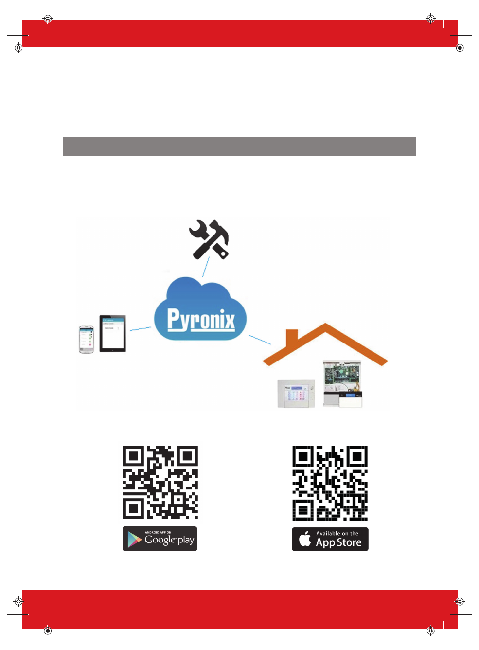
HomeControl+ App
The PCX system can be remotelycontrolled using the HomeControl+App. Itallows you to arm and
disarm the PCX, check the system statusand bypass inputs. It also allows you to activate devices
remotely, such as gates, lights, sprinklers andmore. The HomeControl+ App and PyronixCloud
communication is fully encr ypted to the highest standard and no sensitive user data isstored on the
PyronixCloud.
The HomeControl+Appis available in two versions: Android from Google Play Store and iOS from
Apple store.
6 PCX User Guide 102017853 - V01
Page 7

Operation
Getting Started
Operating the Panel
There are four different methods that can be used in arming or disarming your alarm: using a keypad,
using a proximitytag, a keyfobor the HomeControl+Appon your smart device.
Table 1 -Button Operations
Button Description
a
b
c
d
p
f
[]
1
2
3
t
0
x
Quickly exit a menu.
Select Area A.
Change case when entering text.
Move back to the previous main menui tem.
Select Area B.
Move back to the previous opti on in a sub-menu.
Select Area C.
Displ ay additional informati on in the log.
Delete letters o r numbers whenentering text.
Enables chime feature.
Scroll forward s in the log.
Select Area D.
Access the user menu.
Press and hold to configure the keypad.
Tri gger PA (Panic Alarms) - only if enabled by an engineer.
Tri gger fire alarms - only if enabled by an engineer.
Move from one opti on to another while in a sub-menu.
Move through text.
Select Area 1, 2 or 3.
Also functions the same as the rest of the number / letter keys for entering numbers and text.
Select items and enter into a sub-menu or opti on.
Enter a space when entering text.
Select Area 0.
Scroll forward s in the main menuand sub-menus.
When you have scrolled thro ugh all the optio ns in a menu, returns to the previous menu level.
The Master Manager Menu allows you to setup specific features by asking you a series of setup
questions:
• Main menus are in capital letters and finishwith a question mark, for example, LEARN USE R
CODES KEYFOBS & TAGS?.
• Sub-menus are in lower case letters andfinish with a question mark, for example, User
Codes/Tags/Learn Keyfobs?.
PCX User Guide 102017853 - V01 7
Page 8

• Programmable optionsare in lower case letters anddonotfinish with a question mark, but
t
PCX Enter Your Code Arm Areas Please Wait. . .
Arming Wireless
Arming [029]
Area A
User
Code
User
Code
Stop Arming?
t
t
t
Press the 0, 1, 2, 3, A, B, C or D
keys to select the area to be armed
Time 10:09 c
[******]
[0123ABCD]
[******]
100%9:41 AM
instead: Yes/No, or other options, such as User / Manager.
• To navigate through the menu system, answer the questions in the mainand sub-menus.
For example, if the question is: LEARN USE R CODES KEYFOBS & TAGS?, pressing t willtake
you into the sub-menu User Codes/Tags/Learn Keyfobs?,and pressing t again will then take
you into the programmable options of this sub-menu. If at this pointyou press x, youwill be
taken out of the individual option. Continue topressx and you will navigate through the sub-
menus and eventually return to the mainmenu.
Arming the System
There are four ways that you can arm your system.
1. Enter your User Code on the keypad. The User Code needs to be programmed in the Master
Menu.
2. Present your tag and deselect anyareasthat are not to be armed, then pressthe t button.
Options 1 & 2 only function if ‘Arm Area Choice’ isselectedas ‘Yes’ in the
Codes/Tags/Keyfobs?
menu. If selected as ‘No’, then all areas allocated to your user will
arm.
3. Open the HomeControl+Appon your smart device andsign into your system with your User
Code andpassword details. Then touch the green (disarmed) padlock icons to turn them to red
padlock icons and arm those ar eas.
8 PCX User Guide 102017853 - V01
Learn User
Page 9
For more information, contact your installer.
t
PCX PCXEnter Your Code Disarm Areas
User
Code
t
Press the 0, 1, 2, 3, A, B, C or D keys
to select the area to be armed.
Time 10:09 c
[******] [0123ABCD]
Time 10:09 c
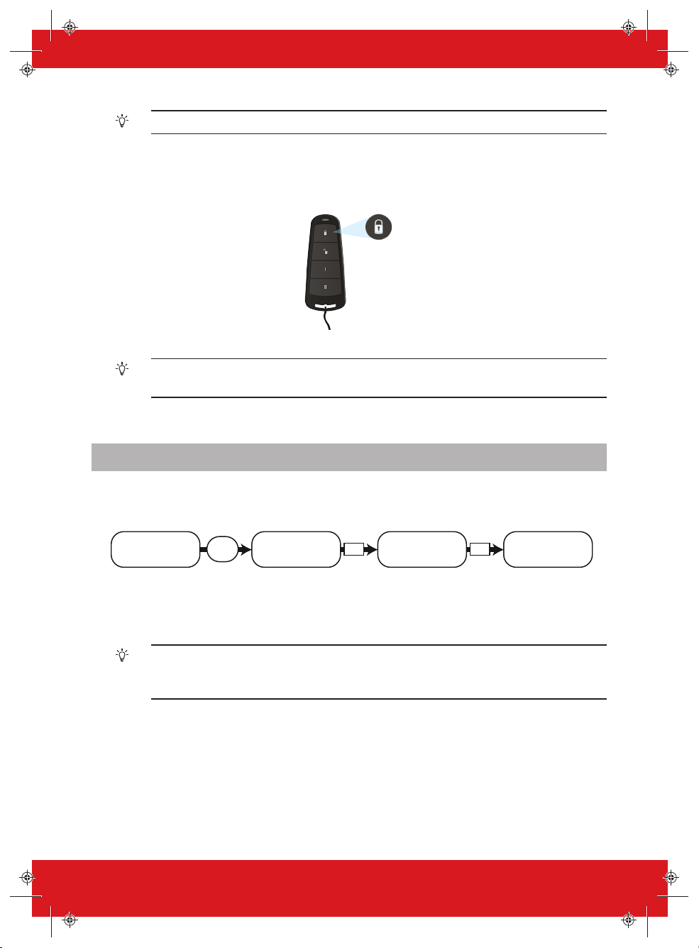
4. Press Î and then release, the keyfobwill arm the areas it has been assigned to by your installer.
A red LED lightwill illuminate when the system is armed.
The keyfobbuttons can be programmed in the Master Manager Menu
Codes/Tags/Keyfobs
.
Learn User
Disarming the System
There are four ways that you can disarm your system.
1. Enter your User Code on the keypad. The User Code needs to be programmed in the Master
Menu.
2. Present your tag and select any areasthat are to be disarmed, then pressthe t button.
Options 1 & 2 only function if ‘Arm Area Choice’ isselectedas ‘Yes’ in the
Codes/Tags/Keyfobs?
menu. If selected as ‘No’, then all areas allocated to your user will
disarm.
Learn User
PCX User Guide 102017853 - V01 9
Page 10
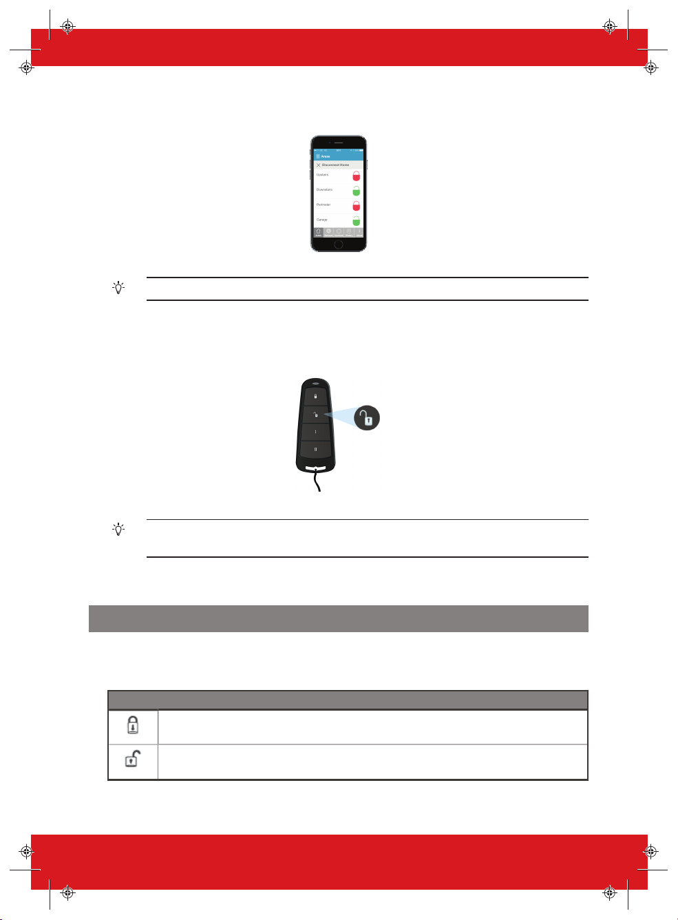
3. Open the HomeControl+Appon your smart device andsign into your system with your User
100%9:41 AM
Code andpassword details. Then touch the red (armed) padlock icons to turn them to green
padlock icons and disarm those areas.
For more information, contact your installer.
4. Press Î and then release, the keyfobwill disarm the areas it has been assigned to by your
installer. A green LED lightwill illuminate to indicate the system is disarmed.
The keyfobbuttons can be programmed in the Master Manager Menu
Codes/Tags/Keyfobs
.
Learn User
Using the Keyfob
The wireless keyfob has four buttons that can be programmed tospecific functions: no action, show
status, arm area, disarm area, latch output, timed output and PA alarm activation. This can be
customised to operate as desired (programmed in the function Change Code).
Button Default configuration
Prog rammed for ‘Arm Area’: one or more areas will be armed when pressed.
Prog rammed for ‘Disarm Area’: one or more areas will be disarmed when pressed.
10 PCX User Guide 102017853 - V01
Page 11
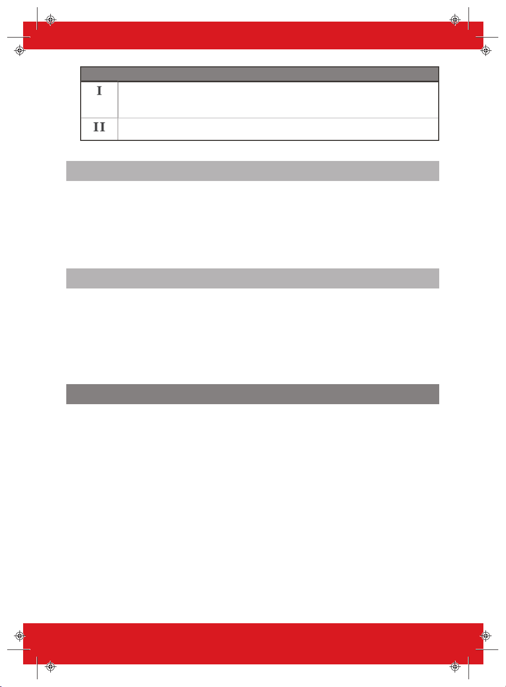
Button Default configuration
Prog rammed for ‘Status LED’. This displays the system status when pressed:
• RED : Armed
• GREEN: Disarmed
• AMBER : Fault
No action.
Locking the Keyfob
All four buttonson the keyfob can be ‘locked’ to prevent you from accidentally pressing them.
To do this, press the two central keys together ( Ï & I ) or the two outer keys together (Î & II ).
A RED LED willflash to indicate that the fobhas been locked. Tounlock the keyfobpress the same
two keys together again and a GREEN LED willflash to indicate that it is now unlocked. Please note
that locking the keyfobdisables all LED indications.
Quick Arming
If you have chosen to program one of the keyfob buttons as ‘Arm Area’, you can then opt to ‘quick
arm’ that area. When you press the button to arm the area, the panel will begin to count down your
exit time (depending on what exit mode has been programmedbyyour engineer). Once this ‘arming
stage’ begins, press the same button on the keyfob again and the system willarm immediately.
The disarm LED on the panel willturn off and a beep willsoundtosignal that the system has been
armed. The RED LED on the keyfobwill illuminate for a short time to confirm this.
Arming and Disarming with the Tag Reader
It is possible to arm and disarm your system using a tag wherever a reader is installed.
To lock and unlock doors using a tag reader, the door must have a magnetic lock that is connected to
the door release output on the reader.
Arming
1. Present a validtag to the reader.
2. The GREEN LED willilluminate on the externalreader (or the disarm LED on the internal reader).
3. Remove the tag.
The door willunlock.
4. Present the same tag within 10 seconds and the system will arm and the door will lock displaying
a RED LED.
Disarming
1. Present a validtag to the reader and then remove it.
The status will be shown (the alarm symbolwill illuminate to indicate that the system is armed on
the internalreader, or the RED LED on the external reader).
2. Present the same tag again within 10 secondsand the system will disarm and the door will
unlock.
PCX User Guide 102017853 - V01 11
Page 12
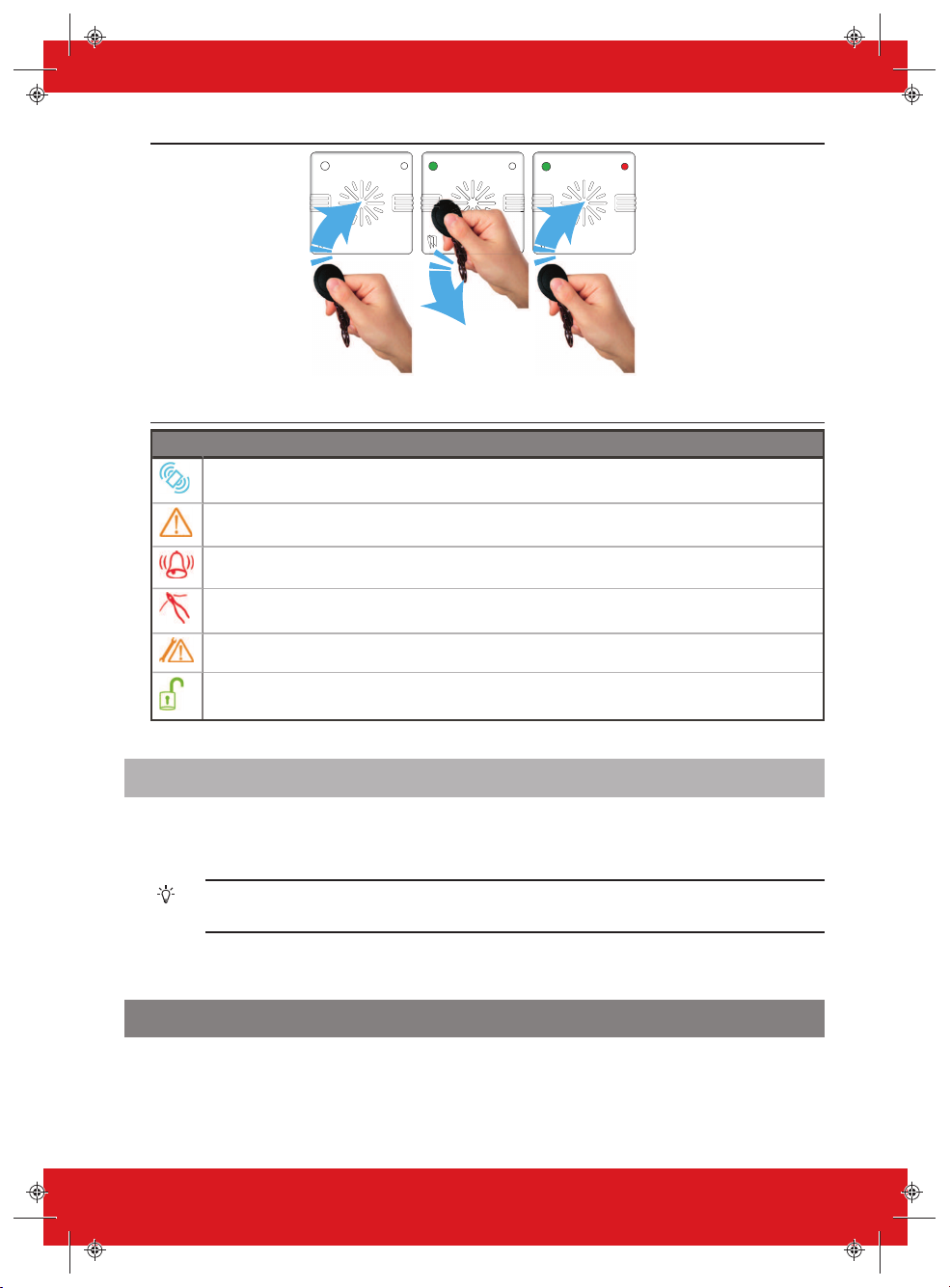
Figure 1: External Tag Reader LEDs(arming shown)
Table 2 -Internal Tag Reader LEDs
LED Description
Tag Area (present tag here)
Ready LED (ready to arm)
Alarm LED (shows alarms)
Tamper LED (shows tamper alarms)
Fault LED (shows system faults)
Unset LED (shows system is disarmed)
Access Control
The readers can also be used for opening doors only, withoutthe abilityto arm or disarm. Please
contact your installer for more information on this feature.
If the system failstoarm, a fault willdisplay on the internaltag reader or a ‘failed to arm’ sound
willactivate on the external tag reader buzzer.
Special Disarm Users
The PCX uses Special Disarm Users, which are users that can signal disarm andspecial disarm.
Special Disarm Users are programmedthe same asstandard users, and are numbers 15-25 in the
LEARN USER CODES KEYFOBS & TAGS? menu.
12 PCX User Guide 102017853 - V01
Page 13
PyronixCloud
Setting up PyronixCloud on the Panel
Check with your Engineer that the panel has been set up to allow communication between the panel
and the cloud/app.
1. Press d and enter your User Code, then press t.
The Master Manager Menu isdisplayed.
2. Scroll to SET UP APP?, and press t.
Enable Appis displayed.
3. Press 1to enable the appand press t.
System ID is displayed.
4. Make a note ofthe System ID and press t.
5. Enter a secure password (max characters =16) for the PyronixCloud, and presst.
6. Press 0tosetSecurity to 'Standard' and press t.
7. Enter a secure password for the HomeControl+Appand press t.
PollServer isdisplayed.
8. If required, choose a PollServer setting and press t.
It is recommended that PollServer isset to Yes.
►
For more information, see "Setting up the PyronixCloud" on page 13
When creating passwords, ensure that the password uses a variety of upper case, lower
case, numbers and symbols – where applicable –toensure the bestsecuritypossible.
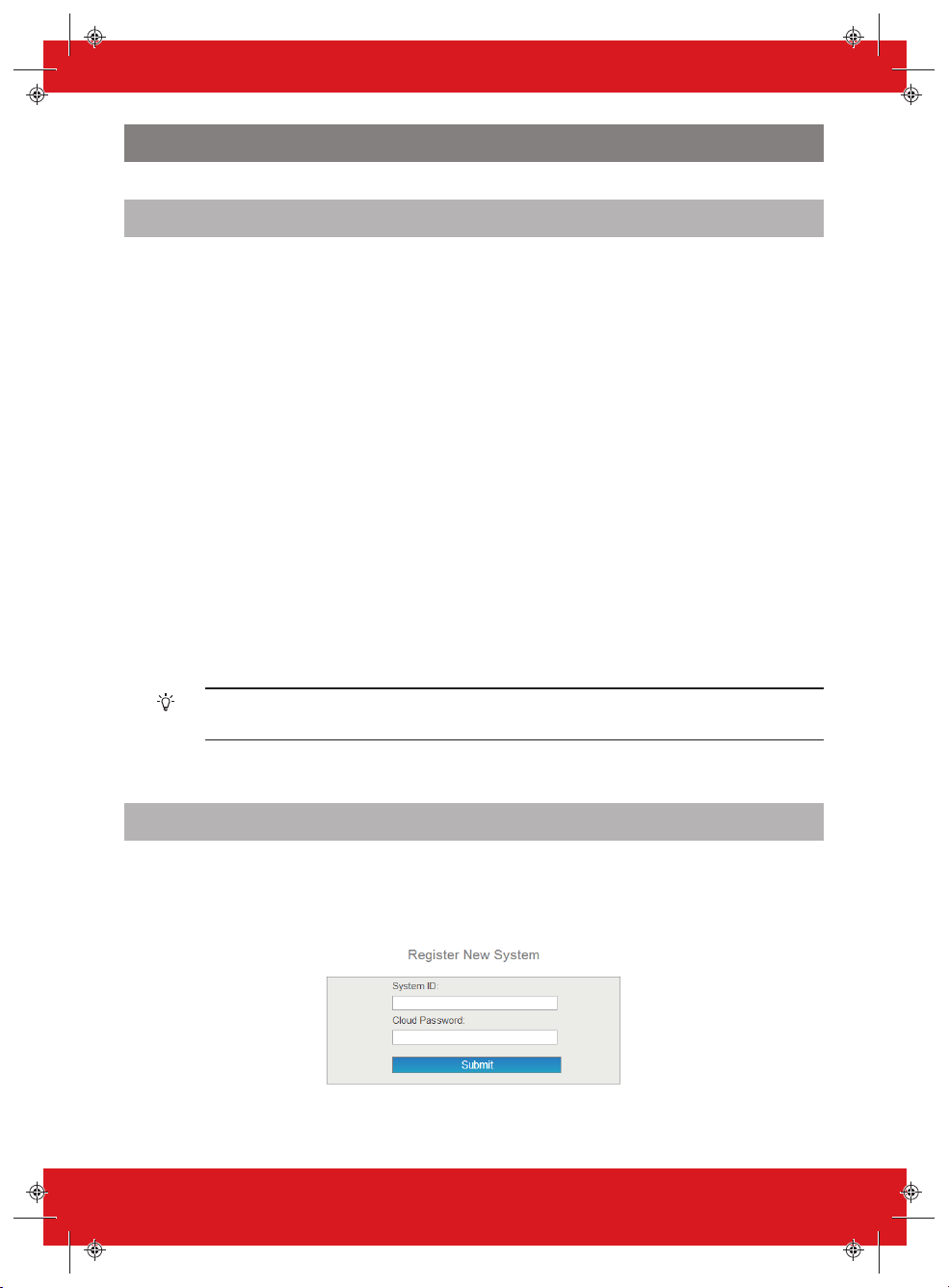
Setting up the PyronixCloud
Log on to www.pyronixcloud.com and create an account.A confirmation email willbe sent to the
registered emailaddress. Once the link on the emailisclicked, you are now set up on the
PyronixCloud.
1. Enter the System ID and Cloud Password that was set up on the panel and click Submit.
PCX User Guide 102017853 - V01 13
Page 14
2. Enter an appropriate System Name.
Thiswill only be used by the Cloud, asyoumay want a differentname on the App.
3. The panel willnow appear on 'View Systems' and 'System Polling' will be displayed on the right.
The green tick shows that the system is connected.
4. Set up the HomeControl+app.
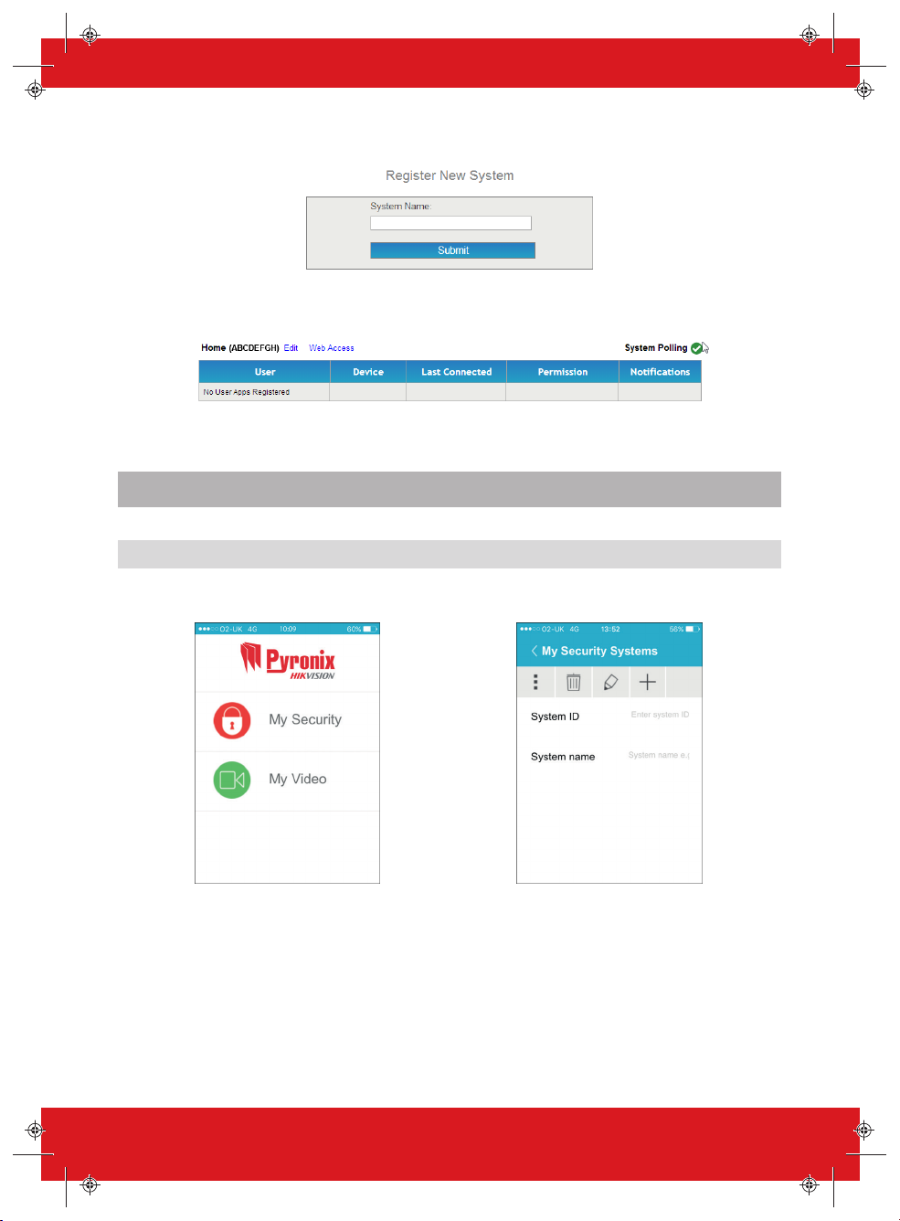
Setting Up The HomeControl+ App
Adding a Panel to the App
1. Open the HomeControl+app and select
My Security.
2. Select +, then enter the System ID and a
System name for your reference.
14 PCX User Guide 102017853 - V01
Page 15

3. Enable and disable the relevant options
and enter the SIM phone number used on
the panel (in the format +447777123456
for example).
The SIM card and phone number options are only applicable when a DIGI-GPRS modem is
installed. This allowsthe smart device to send SMS tothe control panel in order to force the
modem to pollthe cloud. If the panel has been programmed to poll the cloud, these options
are not applicable.
Connecting to a Panel
1. Open the HomeControl+app and select
the system.
PCX User Guide 102017853 - V01 15
2. Enter a validUser Code and the app
password (as enteredin the panel), then
select the tick icon.
Page 16

3. Ensure the HomeControl+appis
authorised on the PyronixCloud. Contact
your engineer if the message below is
displayed.
5. To disconnect, select X next to
Disconnect.
4. If connected successfully, Connected to
your system will be briefly displayed and
then the screen below will be displayed.
All new smart devices, when firstconnected, willbe disabled by default. The cloud
administrator willneed to manually enable these devices before they will be able to connect
to the panel. Thisis an additional security feature to prevent unauthorised access. A panel
can onlybe claimedbyone cloud administrator.
16 PCX User Guide 102017853 - V01
Page 17

HomeControl+ App Icons
MySecurity Area unset
My Video Area set
Settings Area does not exist
Delete Unable to arm area
Edit Area cannot be armed
Add system Detector fault
New notification Area in alarm
Notifications Supervision fault
Search Outputisoff, or option is set to 'no'
Refresh
Disconnect from system
PCX User Guide 102017853 - V01 17
Outputison, or option is set to
'yes'
Page 18

Configuration
Chime Feature
Thisfeature can be setup by your installer and is mostcommonlyenabledfor doors using the
magnetic contact. When activated you willhear a ‘chime’ soundto alert you whenever the door is
opened.
To disable the chime on the panel or keypad, close all doors that chime and press the c key until 'c'
is no longer displayed on the screen.
Press the c key again to re-enable the chime.
PA from Keypad
If you require a PA (Panic Alarm), press and hold both the 1 and 7 keysor hold p for 2 seconds
(by default) and a 'PA' alarm willbe generated.
The PA feature, and the length of time the buttonsmustbe held for, must be enabledbyyour
engineer (silent or audible alarm options available).
Fire Alarm from Keypad
If you want to generate a fire alarm, perform one of the following actions:
• Press andholdboth 3 and 9 for 2seconds.
• Press andholdf for 2 seconds.
The fire alarm feature must be enabledbyyour engineer.
18 PCX User Guide 102017853 - V01
Page 19

Master Manager Menu Options
Bypass Inputs Disables any 24 hour input on the system for t he current disarm p eriod.
Operate User
Outputs
Date & Time Prog rams the date and time and enables the summer-time auto matic adjustment. The timezone can also
Learn User Codes
Keyfobs & Tags
Review Log The 'Review Log’ function is used to vi ew all operatio nal informatio n of the alarm system, such as
Set Up App To use the HomeCo ntr ol+ app, this function must be enabled.
SMS Phonebook If SMS is enabled, up to 10mobile numbers can be programmed for t he panel to send SMS alarms.
Walk Test The ‘Walk Test’ function allows the testing of all pro grammed inputs on the alarm system.
Bell Test This function is used to test the external siren (wired and wireless) and strobe.
Allow Engineer
Menu
Block Remote
Arming
Block UDL Blocks any attempt at dialling into the system remot ely via the upload/do wnload software.
System Sounds
Demo
Exit Manager Mode Exits the Master Manager Menu.
NOTE: Inputs prog rammed as Entry D elay or PA cannot be bypassed
Activates/deactivates user autom ation outputs that are used to r emotely activate devices, such as
electronic gates & lights.
be changed in this menu.
Prog rams the User Codes, tags and learns keyfobs to the panel.
arming/d isarming informatio n, access control and alarm activat ions etc.
Please discuss this feature with your installer if required.
If this functio n is enabled, the engineer will require authori sation from a Master Manager before an
engineer can access the Engineer Menu.
Blocks any attempt at armi ng the system remotely via the upload/do wnload software.
This function demonstrat es the sounds of the panel.
Pressing theakey will exit the Master Manager Menu at anymain menu option above.
Make sure you change the default master manager code.
PCX User Guide 102017853 - V01 19
Page 20

PCX Enter Your Code BYPASS INPUTS?
D
t
Time 10:09 c [******]
Choose an input:
BYPASS INPUTS?
Bypass Inputs [--]
Bypass Inputs [--]
OPERATE USER
OUTPUTS?
Inputs 01
01 to 78
Entering the Master Manager Menu
The default User Code is 1234. We highlyrecommend that you change this code.
Bypass Inputs
20 PCX User Guide 102017853 - V01
Page 21

Select User
Automation Output:
OPERATE USER
OUTPUTS?
Select Output
[01]
Output Off
Output On
DATE & TIME?
B
Pressing t alternates between ON/OFF
then press x when the status
desired is shown - to set it as that)
Turn Output On / Off
[30] Output 30
-
[01] Output 1
Operate User Automation Outputs
PCX User Guide 102017853 - V01 21
Page 22

Options:
[0] No
[1] Yes
DATE & TIME? Year (00-99)Timezone? [117] Month (1-12) Day (1-31) Hours (0-23)
Software Clock
Adjust? [+00]
Summer Time Adj?
LEARN USER CODES
KEYFOBS & TAGS?
B
Minutes (0-59)
Select time zone
Pretoria +02:00
[18]
[01]
[01]
[00]
[00]
No [0]
Date and Time are set automatically on most networks. Youneed to set the time manually when a PSTN modem is installed. GPRS is network
dependant.
Date & Time
22 PCX User Guide 102017853 - V01
Page 23

LEARN USER CODES
KEYFOBS & TAGS?
User Codes/Tags/
Learn Keyfobs?
Enter User Code User Type User in Area
REVIEW LOG?
User Arm Options:
[0] Disarm/Arm
[1] Disarm Only
[2] Arm Only
[3] None
Area Arm Choice:
[0] No
[1] Yes
User Arm Options
User Arm Options
Area Arm Choice
User in Area
User Arm Options:
[0] Disarm/Arm
[1] Disarm Only
[2] Arm Only
[3] None
Area Arm Choice
Area Arm Choice:
[0] No
[1] Yes
User Type:
[0] User
Range:
001 to 100
[1] Manager
Empty [001]
User Name
Master Manager
Code [******]
Change Master
Manager Code?
User Name
Press C Key to
delete code
[******]
User [0]
[0123ABCD]
Disarm/Arm [0]
No [0]
_
[0123ABCD]
Disarm/Arm [0]
No [0]
_
User Codes
Change Codes
PCX User Guide 102017853 - V01 23
Page 24

User Codes/Tags/
Learn Keyfobs?
Enter User Code
Press C Key to
delete code
Present tag
User Type User in Area
User Arm Options:
[0] Disarm/Arm
[1] Disarm Only
[2] Arm Only
[3] None
Area Arm Choice:
[0] No
[1] Yes
User Arm Options Area Arm Choice User Name
User Type:
[0] User
[1] Manager
Empty [001]
Range:
001 to 100
[ ]
User [0]
[0123ABCD]
Disarm/Arm [0]
No [0] _
Proximity Tags
Arm Area Choice: If selected as ‘Yes’ you willbe able to choose the area you wish to arm after you have entered your User Code or presented a valid
tag. If selected as‘No’, the PCX will automatically arm all areas the panel/code is assigned to.
24 PCX User Guide 102017853 - V01
Page 25

User Codes/Tags/
Learn Keyfobs?
Enter User Code
User Name
Press and hold any
button for 5 seconds
until LEDs flash
Select Button Button Action [1]
If Arm Area
or Disarm Area
If Operate Output
Output [170]
User in Area
Output:
Button Action:
[0] No Action
[1] Show Status
[2] Arm Area
[3] Disarm Area
[4] Operate Output
[6] PA (Panic Alarm - only for 2 button
options)
Select Button:
[1] Button LOCK
[2] Button UNLOCK
[3] Button I
[4] Button II
[5] Buttons LOCK + UNLOCK
[6] Buttons I + II
[7] Buttons LOCK + I
[8] Buttons UNLOCK + II
Press C Key to
delete code
Empty [001]
Range:
001 to 100
Maximum of 30 keyfobs
[ ]
_
Button [1] Show Status
[0123ABCD]
User Defined 1
[170-199] User Defined 1-30
Keyfobs
Keyfobscan only be learnttothe PCX if a PCX-RIX32-WE is installed (Enforcer wireless expander).
PCX User Guide 102017853 - V01 25
Page 26

To obtain more information on the event Press c
REVIEW LOGS?
SET UP APP?
Panel Log?
01/01 00:11:44
User 01
Repeat for all
Events
Start of Log
To obtain more information on the event Press c
Access/Ctrl Log? 01/01 00:11:44
User 01
Repeat for all
Events
Start of Log
C
C
B
User Open Door
Alarm Silenced
26 PCX User Guide 102017853 - V01
Review Log
Page 27

Poll Server?:
SET UP APP?
Enable App System ID
Cloud Password:
Security
Poll Server?
App Password:
SMS PHONEBOOK?
B
Enable App:
Security:
No [0] AAAAAAAA
Normal [0]
_
Yes [1]
[0] No
[1] Yes
[1] Yes
[0] No
[1] High
[0] Normal
PCX User Guide 102017853 - V01 27
Standard Security
Setup App Data
Page 28

SET UP APP? Enable App System ID Cloud Password:
Security
Are You Sure?
Generate App
Password Key?
Poll Server?
Key Part 1 ABCD
-ABCD-ABCD-ABCD
Key Part 2 ABCD
-ABCD-ABCD-ABCD
Key Part 2 ABCD
-ABCD-ABCD-ABCD
View App Password
Key?
SMS PHONEBOOK?
B
Mobile#
Send Password
key in a text
Password sent
successfully
Key Part 1 ABCD
-ABCD-ABCD-ABCD
Yes [1]
AAAAAAAA High [1]
Yes [1]
Enable App:
[0] No
[1] Yes
Security:
[1] High
[0] Normal
Poll Server?:
[1] Yes
[0] No
High Security
28 PCX User Guide 102017853 - V01
Page 29

SMS Number:
SMS PHONEBOOK? SMS Numbers
User Mobile:
WALK TEST?
B
_
[01] - [10]
SMS Phonebook
Mobile numbers can be entered with or withoutan international dialling code (e.g. +44). If you need to enter an internationaldiallingcode to send the key
to a foreign SIM card,use the a key to enter the ‘+’ symbol.
PCX User Guide 102017853 - V01 29
Page 30

WALK TEST? Walk Test Areas
Walk Test Input
Input 01
BELL TEST?
B
[0123ABCD]
[01]
BELL TEST? Testing Bell...
ALLOW ENGR MENU?
B
Walk Test
30 PCX User Guide 102017853 - V01
When walk testingareas, walk around to trigger all of the Inputs in the selected areas until the panel displaysWalk/Mask TestInputsCompleted.When
using the Walk Test Input option to choose a specific Input to test, the keypadwill make an audible ‘beep’ each time the Inputistriggered.
Bell Test
Page 31

Allow Engineer Menu:
ALLOW ENGR MENU? Allow Engr Menu?
BLOCK REMOTE
ARMING?
B
Yes [1]
[0] No
[1] Yes
Block remote arm:
BLOCK REMOTE
ARMING?
Block Remote Arm
BLOCK UDL?
B
No [0]
[0] No
[1] Yes
PCX User Guide 102017853 - V01 31
Thisfunctionwill block anyattempt made to ar m or disarm via the UDL software if enabled.
Allow Engineer Menu
Block Remote Arming
Page 32

Block UDL:
BLOCK UDL? Block UDL?
SYSTEM SOUNDS
DEMO?
B
[1] Yes
[0] No
No [0]
Sound Demo Options:
SYSTEM SOUNDS
DEMO?
Sounds Demo
B
PRESS A TO EXIT
& SAVE MAN MENU?
No Sound [00]
[00] No Sound
[01] Chime Single
[02] Chime Follow
[03] Exit
[04] Exit Fault
[05] Entry
[06] Tech Fault
[07] Tamper
[08] Alarm
[09] PA
[10] Fire
32 PCX User Guide 102017853 - V01
Thisfunctionwill block anyattempt made to dial into the control panel to upload and download information if enabled.
Block UDL
System Sounds Demo
Page 33

Press the a key to exit Master
Manager mode from any main menu
item (displayed in capital letters)
EXIT MANAGER
MODE?
PCX BYPASS INPUTS? PCX
BYPASS INPUTS?
B
A
OR:
Time 10:09 c
Time 10:09 c
Exit Master Manager Menu
PCX User Guide 102017853 - V01 33
Page 34

Reference
Handover Form
Alarm Comp any:
Date of Installation:
Site Reference:
Engineer Name:
Engineer Contact Number:
Installed to Grade 2: Yes / No
Environmental Class:
Other Comments:
SMS Commands
You can send SMS commandsto the panel via your mobile phone.
All SMS commands must start with a valid User Code and are not case sensitive unless the
utilised outputs are activated. If an SMS command is not recognised, the panel will send an
‘incorrect command’ message back to you.
Example SMS command send Description Examp le SMS command
Arming via SMS text command
1234 Arm 0 1234 = User Code. Arm 0 = Wi ll arm in
Areas 0
1234 Arm ABCD0123 1234 = User Code. Arm ABCD0123 = Will
arm in Areas ABCD0123
NOTE: If no areas are specified then all areas will arm (default).
Disarming via SMS text command
response
Final Arm; Area 0
Final Arm; Area ABCD0123
34 PCX User Guide 102017853 - V01
Page 35

Example SMS command send Description Examp le SMS command
response
1234 Disarm 0
1234 Disarm ABCD0123 1234 = User Code. Disarm ABCD0123=
NOTE: If no areas are specified then all areas will disarm (default).
1234 = User Code. Disarm 0 = Will disarm
in Area 0
Will disarm in Areas ABC D0123.
Disarm; Area 0
Disarm; Area ABCD0123
Arming with inputs byp assed via SMS text command
1234 Arm 0 Byp ass 4
1234 Arm 0 Byp ass Kitchen 1234 = User Code. Arm 0 Bypass Kitchen =
1234 = User Code. Arm 0 Bypass 4 = Arms
Area 0and will byp ass Input 4
Arms Area 0 and wi ll bypass the Inp ut
named Ki tchen.
Input Bypass; Area 0 Input 04
For ce Arm: Area 0
Input Bypass; Area 0 Kitchen
For ce Arm: Area 0
Bypassinginputs via SMS text command
1234 Bypass 6
1234 Bypass Garage 1234= User Code. Bypass Garage = In the
NOTE: Output names have to be one word and spelled exactly as writt en in the panel e.g. Gar age Door is not acceptable. It has
to be writt en as Garage-Door i n the panel and the respective command will be Garage-Do or.
1234 = User Code. Bypass 6= In the next
arming pro cedure, Input 6 will be
bypassed.
next arming pro cedure, and will byp ass the
Input named Garage.
Input Bypass; Area 0 Input 06
Input Bypass; Area 0 Garage
Checking the system status via SMS text command
1234 Status 1234 = User Code. Status. Area 0 Disarmed No F aul ts
Area 1D isarmed No Faults
Area 2D isarmed No Faults
Area 3D isarmed No Faults (etc.)
Operating the user automationoutputs via SMS text commands
1234 Output 1 On 1234= U ser Code. User Output 1 turns on. OUTPUT 1 ON
1234 Output Garage-Door On 1234 = User Code output
1234 Output Garage-Door Off 1234 = User Code output
NOTE: Output names have to be one word and spelled exactly as writt en in the panel e.g. Gar age Door is not acceptable. It has
to be writt en as Garage-Door i n the panel and the respective command will be Garage-Do or.
NOTE: The user automatio n outputs can al so be activated via the keypad or the keyfob.
Garage-Door on = Turns output named as
Garage-Door on.
Garage-Door off = Turns output named as
Garage-Door off.
OUTPUT Garage-Do or ON
OUTPUT Garage-Do or OFF
Checking the user automation outputs status via SMS text commands
1234 Output 1 1234 = User Code. User Output 1 status
check.
1234 Output Garage-Door St atus 1234 = User Code. Output Garage-Door
status check.
NOTE: Output names have to be one word and spelled exactly as writt en in the panel e.g. Gar age Door is not acceptable. It has
to be writt en as Garage-Door i n the panel and the respective command will be Garage-Do or.
OUTPUT 1 ON or OUT PUT 1 OFF
OUTPUT Garage-Do or ON or
OUTPUT Garage-Do or OFF
PCX User Guide 102017853 - V01 35
Page 36

Example SMS command send Description Examp le SMS command
response
Changinga mobile number via SMS text commands
1234 Change 07777888999 07878888999 1234 = User Code. Change number
07777888999 to number 07878888999
NOTE: Use the appropr iate internatio nal dialling code (e.g. +44) when necessary (i.e. for foreign SIM cards). For example if you
wanted to message a foreign SIM card at your holid ay home abro ad. When you send the SMS command, ensure you enter a
space between the two mob ile numbers.
CHANGE 07878888999
Inputs
Inputs Input
Name
1 40
2 41
3 42
4 43
5 44
6 45
7 46
8 47
9 48
10 49
11 50
12 51
13 52
14 53
15 54
16 55
17 56
18 57
19 58
20 59
21 60
22 61
23 62
24 63
25 64
26 65
27 66
Input
Areas
Description I nput Input
Name
Input
Areas
Description
36 PCX User Guide 102017853 - V01
Page 37

Inputs Input
Name
28 67
29 68
30 69
31 70
32 71
33 72
34 73
35 74
36 75
37 76
38 77
39 78
Input
Areas
Description I nput Input
Outputs
Wired Outputs Latched / Timed Type Action
PGM (Onboard )
STB (Onboard )
BELL(Onboard )
XPGM1 (Input 7)
XPGM1 (Input 8)
PGM1 (KPD/TRD
Address 1)
PGM1 (KPD/TRD
Address 2)
PGM1 (KPD/TRD
Address 3)
PGM1 (ROX Address 0)
PGM2 (ROX Address 0)
PGM3 (ROX Address 0)
PGM4 (ROX Address 0)
PGM5 (ROX Address 0)
PGM6 (ROX Address 0)
PGM7 (ROX Address 0)
PGM8 (ROX Address 0)
PGM9 (ROX Address 0)
PGM10(ROX Address 0)
PGM11(ROX Address 0)
Name
Input
Areas
Description
PCX User Guide 102017853 - V01 37
Page 38

Wired Outputs Latched / Timed Type Action
PGM12(ROX Address 0)
PGM13(ROX Address 0)
PGM14(ROX Address 0)
PGM15(ROX Address 0)
PGM16(ROX Address 0)
PGM1 (ROX Address 1)
PGM2 (ROX Address 1)
PGM3 (ROX Address 1)
PGM4 (ROX Address 1)
PGM5 (ROX Address 1)
PGM6 (ROX Address 1)
PGM7 (ROX Address 1)
PGM8 (ROX Address 1)
PGM9 (ROX Address 1)
PGM10(ROX Address 1)
PGM11(ROX Address 1)
PGM12(ROX Address 1)
PGM13(ROX Address 1)
PGM14(ROX Address 1)
PGM15(ROX Address 1)
PGM16(ROX Address 1)
PGM1 (RIX Address 0)
PGM2 (RIX Address 0)
PGM3 (RIX Address 0)
PGM4 (RIX Address 0)
PGM1 (RIX Address 1)
PGM2 (RIX Address 1)
PGM3 (RIX Address 1)
PGM4 (RIX Address 1)
PGM1 (RIX Address 2)
PGM2 (RIX Address 2)
PGM3 (RIX Address 2)
PGM4 (RIX Address 2)
PGM1 (RIX Address 3)
PGM2 (RIX Address 3)
PGM3 (RIX Address 3)
PGM4 (RIX Address 3)
PGM1 (RIX Address 4)
38 PCX User Guide 102017853 - V01
Page 39

Wired Outputs Latched / Timed Type Action
PGM2 (RIX Address 4)
PGM3 (RIX Address 4)
PGM4 (RIX Address 4)
PGM1 (RIX Address 5)
PGM2 (RIX Address 5)
PGM3 (RIX Address 5)
PGM4 (RIX Address 5)
PGM1 (RIX Address 6)
PGM2 (RIX Address 6)
PGM3 (RIX Address 6)
PGM4 (RIX Address 6)
PGM1 (RIX Address 7)
PGM2 (RIX Address 7)
PGM3 (RIX Address 7)
PGM4 (RIX Address 7)
ATE PGM 1
ATE PGM 2
ATE PGM 3
ATE PGM 4
ATE PGM 5
ATE PGM 6
ATE PGM 7
ATE PGM 8
ATE PGM 9
Users
User Name Code/Tag/
Keyfob
1 35 69
2 36 70
3 37 71
4 38 72
5 39 73
6 40 74
7 41 75
8 42 76
9 43 77
PCX User Guide 102017853 - V01 39
User Name Code/Tag/
Keyfob
User Name Code/Tag/
Keyfob
Page 40

User Name Code/Tag/
Keyfob
10 44 78
11 45 79
12 46 80
13 47 81
14 48 82
15 49 83
16 50 84
17 51 85
18 52 86
19 53 87
20 54 88
21 55 89
22 56 90
23 57 91
24 58 92
25 59 93
26 60 94
27 61 95
28 62 96
29 63 97
30 64 98
31 65 99
32 66 100
33 67
34 68
User Name Code/Tag/
Keyfob
User Name Code/Tag/
Keyfob
Compliance
As per EN 50131-1 the PCX is capable of supporting all conditions A,BandC:
In Grades 1 & 2 I&HAS when an I&HAS or part thereof is ina set state:
a. accesstothe supervisedpremisesor partthereof, via an entry/ex itroute, shall be pr evented,
or
b. openingthe door to the entry/exit route shallinitiate an entry procedure, or
c. indication of the set/unset status shallbe provided.
In Grades 3 & 4 I&HAS when an I&HAS or part thereof is ina set state:
a. accesstothe supervisedpremisesor partthereof, via an entry/ex itroute, shall be pr evented,
or
b. openingthe door to the entry/exit route shallinitiate an entry procedure.
App HomeControl+ not cer tified IMQ-Security Systems.
40 PCX User Guide 102017853 - V01
Page 41

2
EN50131-3:2009
3
EN50131-1:2008+A1:2009
Security Grade 2
Environmental Class II
EN50131-3:2009
EN50131-1:2008+A1:2009
Security Grade 3
Environmental Class II
For electrical products sold within the Eur opean Community.
At the end of the electrical productsuseful life, it shouldnotbe disposed ofwith householdwaste.
Please recycle wher e facilities exist. Check withyour Local Authority or retailer for recycling advice
in your country. When disposing of the pr oduct and accessories,the batteries must be removedand
disposedof separately in accordance with the local regulations.
PCX User Guide 102017853 - V01 41
Page 42

Notes
42 PCX User Guide 102017853 - V01
Page 43

Page 44

 Loading...