

Page 1

Page 2

PCX 46 App Installation Reference
Page: 2
A. Contents Page
A. Contents Page .................................................................................................................... 2
1. System Overview ..................................................................................................................... 3
1.1 The Devices ........................................................................................................................ 4
1.2 PCX 46 App Input Mapping Overview: ........................................................................................ 6
1.3 PCX 46 App Output Mapping ..................................................................................................... 6
2. Out of the box ......................................................................................................................... 7
3. The Printed Circuit Board ........................................................................................................... 8
3.1 Technical Specification .......................................................................................................... 9
3.2 Important Installation Notes ................................................................................................ 10
3.3 Communication Loom ......................................................................................................... 11
3.4 Power and Battery Connections for the PCX 46 APP L ................................................................. 12
3.5 Power and Battery Connections for the PCX 46 APP S ................................................................ 13
4. Input Connections .................................................................................................................. 14
4.1 Normally Closed Input Wiring .............................................................................................. 14
4.2 Grade 2 DEOL (Double End of Line) Input Wiring .................................................................... 15
4.3 Grade 3 Mask/Fault Input Wiring .......................................................................................... 15
5. Output (PGM) Connections ...................................................................................................... 16
5.1 XPGM Connections ............................................................................................................. 16
6. External Sounder Connections .................................................................................................. 17
6.1 Grade 3 External Sounder Wiring ......................................................................................... 17
6.2 Grade 2 External Sounder Wiring with a Grade 3 Bell .............................................................. 17
6.3 Grade 2 External Sounder Wiring ......................................................................................... 18
7. Connecting the PCX Peripherals ................................................................................................ 19
7.1 Connecting The PCX-LCD Keypad (PCX-LCD/EX)..................................................................... 19
7.2 Connecting The Internal Tag Reader (PCX-PROX/INT) ............................................................. 22
7.3 Connecting The External Proximity Reader (PCX-EXT-BK) ........................................................ 24
7.1 Connecting The PCX-RIX8i (Remote Input Expander with Inertia) ............................................. 27
7.2 Connecting The PCX-RIX8+ (Remote Input Expander with 4 PGMs) ........................................... 31
7.3 Connecting The PCX-RIX8+PSU (Remote Input Expander with PSU) .......................................... 35
7.4 Connecting The PCX-RIX32-WE (Remote Wireless Expander) ................................................... 39
7.5 Connecting The PCX-ROX8R8T (Remote Output Expander) ...................................................... 41
7.6 Connecting The PCX-ROX16R+PSU Expander (Remote Output Expander with PSU) ..................... 43
8. The GPRS, LAN and PSTN Modems ............................................................................................ 45
8.1 The PSTN Modem (Digi-1200) .............................................................................................. 46
8.2 The GPRS Modem (DIGI-GPRS) ........................................................................................... 47
8.3 The LAN Modem (Digi-LAN) ................................................................................................. 47
8.4 Connecting to the Upload/Download Software ........................................................................ 48
9. EN 50131 Terminology ............................................................................................................ 50
10. Access Levels ....................................................................................................................... 50
11. Compliance ......................................................................................................................... 50
NOTES ..................................................................................................................................... 51
Page 3

PCX 46 App Installation Reference
Page: 3
1. System Overview
The PCX 46 App is wired control panel that can have a maximum of 46 inputs. There are two versions
available: PCX 46 App S = Small box (Security Grade 2), PCX 46 App L = Large box (Security Grade 3).
They are both compatible with Two Way Enforcer wireless peripherals using the PCX-RIX32-WE.
System Overview
PCX 46 App S PCX 46 App L
Additional Information
Areas:
Independent areas 8
Sub areas 7 Each sub-area is created by a proximity reader
Inputs:
Wired inputs 8 On board Supports Double Pole (N/C), DEOL and 3EOL
Wireless inputs 32 32 = 1 x Wireless input expander: PCX-RIX8
Maximum inputs 46
46 = 4 x Wired/wireless input expanders: PCX-RIX8, PCXRIX8+, PCX-RIX8+PSU, PCX-RIX32-WE.
3 x Keypads/readers: PCX-LCD/EX, PCX-PROX/EXT, PCXPROX/INT
PGM Outputs:
PCB 5 (3 and 2)
1 Relay, 4 transistor (Inputs 7 & 8 may be used as
outputs)
ATE outputs 10 Low power ATE outputs
Maximum PGM outputs 69
69 = 3 x Outputs on the PCB
2 x Shared outputs: XPGM 1&2 (Inputs 7&8)
2 x Output expanders: PCX-ROX8R8T, PCX-ROX16R+PSU
4 x Wired input expanders: PCX-RIX8+, PCX-RIX8+PSU
each have 4 outputs on board.
6 x Keypads or 1 x Keypad & 3 x Readers: 6 outputs
10 x ATE PGMs
User automation outputs 30
Allows users to activate these outputs via keypad (PCXLCD/EX), mobile app, or keyfob (KF4-WE)
Codes:
Wireless key fobs 32 Using 1 x Wireless expander: PCX-RIX32-WE
Maximum user codes 100 + 1 Master Including wireless keyfobs: KF4-WE
Duress / guard codes 10
Engineer codes 1
Arming Devices
Arming devices 6 Maximum PCX-LCD/EX, PCX-EXT-BK/W, PCX-PROX/INT
Communication
Phone numbers 25
Modems /
Communication paths
PSTN, GPRS, LAN, GSM
PSTN modem (DIGI-1200) GSM modem (DIGI-GSM)
GPRS modem (DIGI-GPRS) LAN modem (DIGI-LAN)
Formats for ARC
PSTN or VOICE PSTN: SIA Levels 1 & 3, CONTACT ID (Voice PSTN for future use)
GPRS or LAN or WiFi: SIA IP, CONTACT ID IP (WiFi for future use)
GSM: CONTACT ID
Formats for User SMS
SMS signals to a user's mobile phone. Also allows user
remote control panel via SMS commands
Event Signaling UDL Yes Using the upload/download software (UDL)
Logs:
Memory logs 1250
Memory type EEPROM
Power Rating:
PSU 1.5A 2.0A Power supply built onboard
Battery type 3-6Ah 7-17Ah Recommended batteries
Dimensions and Compliance
Dimensions:
250 x 297 x
82mm
390 x 305 x
100mm
PCB: 170 x 110 x 40mm
EN grading* Grade 2 Grade 3
Environment class II II
Default Codes: Master Manager Code: 1234 Engineer Code: 9999
*EN50131 compliance labeling should be removed if non-compliant configurations are used.
NOTE: Technical functions for example fire, gas and flooding are not security graded as they are outside
the scope of EN50131-1 and EN50131-3
Page 4
PCX 46 App Installation Reference
Page: 4
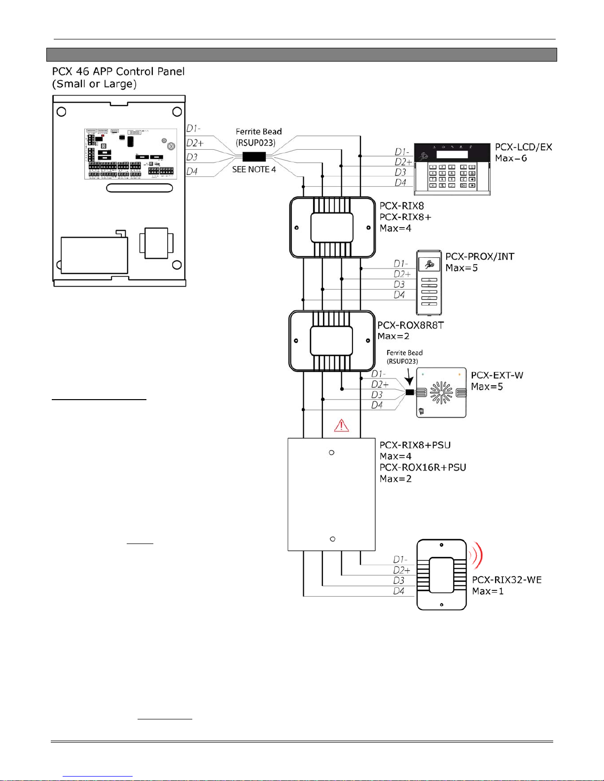
1.1 The Devices
NOTE 5: (IMPORTANT!) If an expansion module with a power supply on board is connected,
the D2+ terminal MUST NOT be connected between the main bus and module.
All PCX peripherals; LCD keypads,
readers, expanders etc. are connected
via the D1-, D2+, D3 and D4 terminals.
This is an example of what a typical PCX
bus may look like.
General Principles:
NOTE 1: No alarm system cable should
be run with other cables carrying AC or
digital signals.
NOTE 2: The cables should be
protected by the use of grommets
where appropriate.
NOTE 3: For greater than 1000m range
a standard isolated RS485 repeaters
required.
NOTE 4: There MUST be a ferrite bead
fitted to one of the outgoing data lines
and secured inside the PCX case itself.
The Ferrite bead is supplied packaged
with a cable-tie which must be used to
secure it in the case and prevent it
shorting any electrical contacts (Ferrite
as shown).
There must also be a ferrite bead fitted
to the data wires of a PCX-EXT-BK/W (if
connected). The Ferrite bead is supplied
with the reader.
Page 5

PCX 46 App Installation Reference
Page: 5
1.1.1 RS-485 Wiring
Cable type Screened Cable
Bus range
(m)
Wiring Format
Daisy Chain Range Star Range
4 core alarm cable
Use when bus
located near
230VAC mains
power line
300m
No limit. 50m
6 core alarm cable
doubling D1 (0v)
and D2 (12v)
1000m
Twisted pair 1000m
Daisy Chain Wiring Diagram
Example #1
Daisy Chain Wiring Diagram
Example #2
Page 6
PCX 46 App Installation Reference
Page: 6
1.2 PCX 46 App Input Mapping Overview:
DEVICES
Address
Input Numbers
PCX 46 App PCB PCB 1-8
PCX-RIX8 / PCX-RIX8+/ PCX-RIX8+PSU /PCX-RIX32-WE 0 9-16
PCX-RIX8 / PCX-RIX8+/ PCX-RIX8+PSU /PCX-RIX32-WE 1 17-24
PCX-RIX8 / PCX-RIX8+/ PCX-RIX8+PSU /PCX-RIX32-WE 2 25-32
PCX-RIX8 / PCX-RIX8+/ PCX-RIX8+PSU /PCX-RIX32-WE 3 33-40
PCX-LCD/EX 0 41-42
PCX-LCD/EX / PCX-PROX/INT* 1 43-44
PCX-LCD/EX / PCX-PROX/INT* 2 45-46
Total 46
NOTE 1: 1 x PCX-RIX32-WE can be connected to the PCX 46 App. This expander allows 32 inputs which
are separated into 4 addresses (each address enables 8 wireless inputs). It is possible to mix the wired
and wireless remote expanders. For more information please see page: 39.
*NOTE 2: If the PCX-PROX/INT (Internal Tag Reader) is programmed as an 'Arm/Disarm' device, 2
inputs are enabled. If the PCX-PROX/INT is programmed as 'Entry Cont rol' or 'Access Control' only 1
input is enabled.
1.3 PCX 46 App Output Mapping
DEVICES
Address
Output Numbers
PCX 46 App PCB PCB 5 (2 shared)
Digi/ATE Outputs (using communication loom) Loom 10
PCX-ROX8R8T / PCX-ROX16R+PSU 0 1-16
PCX-ROX8R8T / PCX-ROX16R+PSU 1 17-32
PCX-RIX8+/ PCX-RIX8+PSU 0 1-4
PCX-RIX8+/ PCX-RIX8+PSU 1 1-4
PCX-RIX8+/ PCX-RIX8+PSU 2 1-4
PCX-RIX8+/ PCX-RIX8+PSU 3 1-4
PCX-LCD/EX 0 1
PCX-LCD/EX / PCX-PROX/INT / PCX-EXT-BK/W 1 1
PCX-LCD/EX / PCX-PROX/INT / PCX-EXT-BK/W 2 1
PCX-LCD/EX / PCX-PROX/INT / PCX-EXT-BK/W 3 1
PCX-LCD/EX / PCX-PROX/INT / PCX-EXT-BK/W 4 1
PCX-LCD/EX / PCX-PROX/INT / PCX-EXT-BK/W 5 1
Total 69
Page 7
PCX 46 App Installation Reference
Page: 7
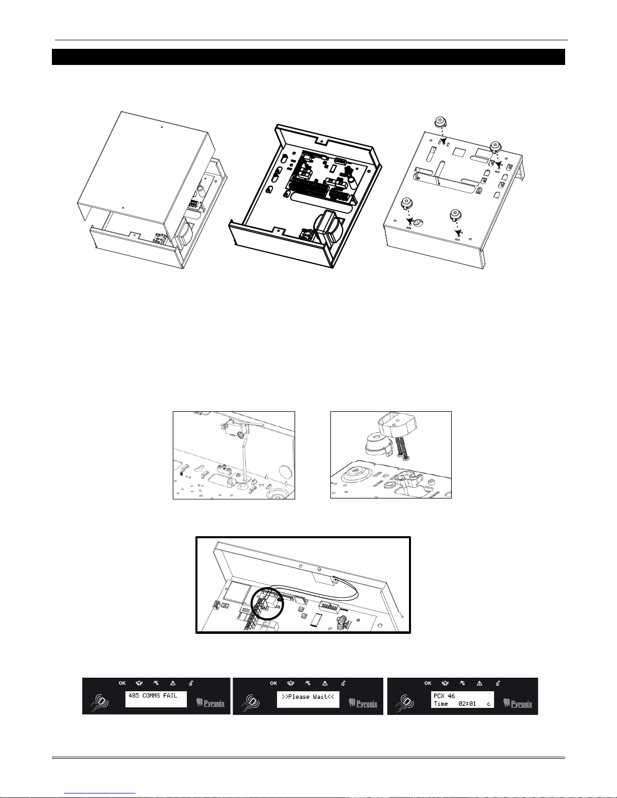
2. Out of the box
1. Unscrew and remove the cover of the PCX 46 App (Figure 1). The PCX 46 App Printed circuit
board is located to the top right hand side. (Figure 2)
2. Install the supplied stand offs if needed before mounting the metal case to the wall ( Figure 3).
Figure 1. Figure 2. Figure 3.
3. Connect any modems if required and any other devices (input expanders, output expanders
etc.) before powering up the system.
4. Wire the telephone line if the DIGI-1200 modem (PSTN) is installed. See page 45.
5. Install the SIM card, connect the antenna and locate outside of the metal casing if the GPRS
modem is used. See page 45.
6. Screw the back metal plate to the wall.
7. PCX 46 App Large Box: The tamper mechanism comes already fitted and will operate properly
once the casing is fitted to the wall. If using the stand-offs, the following will need to be used
for the rear tamper mechanism to work correctly.
8. PCX 46 App Small Box: The tamper mechanism comes already fitted.
9. Secure all the wires and close the enclosure making sure the tamper is operational
10. Turn on the power to the PCX 46 App. The keypad will show:
Page 8
PCX 46 App Installation Reference
Page: 8
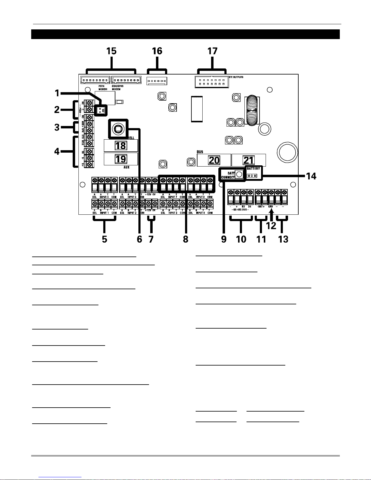
3. The Printed Circuit Board
1: Case Tamper Hold-Off Jumper
2: PGM 1 (Relay output. See page: 16)
3: Speaker connection
Connects a 16ohm speaker. See page: 16
4: External sounder connections
Connects an external sounder. See page: 17.
5: Input connections
8 Fully programmable inputs.
See page: 13.
6: Tamper Switch
Optional tamper protection for the metal casing
7: Auxiliary 12V power
12V power supply
8: Inputs or Outputs
Inputs 7 and 8 may be programmed as outputs if
unused. See page: 16
9: Battery Connect ‘Kickstart’ switch
To power-up and program from battery power
(when there is no mains power available).
10: RS485 bus terminals
Connects peripherals. See pages: 4 and 19
11: Battery connection:
For battery power up. See page: 12
12: Earth connection
Connects the earth
13: 17V connection
Connects the AC transformer 17V supply
14: Battery Charge Capacity Jumper
For battery power up. See page: 12
15: PSTN, GPRS & LAN Modems
Connects PSTN, GPRS & LAN modems.
See page: 45 onwards
16: RS232 Connection
This connection is used for an RS232 lead that
will connect to a PC to allow uploading and
downloading of data using the InSite software
(see page: 48)
17: Communication Outputs
Connects the supplied communication loom to
enable an additional 10 programmable outputs.
These are low current and would normally be
used when connecting a stand-alone
communicator to the panel (see page: 11).
18: Bell Fuse 19: Auxiliary Fuse
20: Bus Fuse 21: Battery Fuse
Page 9

PCX 46 App Installation Reference
Page: 9
3.1 Technical Specification
Programmable
Outputs Power Rating Normal State Active State
PGM 1 Relay, 3A, max 30V Changeover NC & NO Changeover NC & NO
Speaker 16 ohms No tones Repeat RKP tones & internal sounder
Strobe Output 500mA 12v 0v
Bell Output 500mA 12v 0v
XPGM 1 (Input 7) 50mA Floating 0v
XPGM 2 (Input 8) 50mA Floating 0v
ATE Outputs 2mA 5v 0v
All outputs are programmed in "PROGRAM OUTPUTS?" in the Engineer menu.
Input Resistance 1k / 1k DEOL Range 4k7 / 2k2 DEOL Range
Normal 0k5 to 1k4 1k4 to 2k9
Burglary Alarm 1k5 to 5k9 4k2 to 7k8
Tamper <0k5 or <17k <1k4 or >22k
All inputs are programmed in "PROGRAM INPUTS?" in the Engineer menu.
Fuses Value Type
Bell Fuse for bell terminals F800mA quick blow 250V Glass
Aux Fuse for aux terminals F800mA quick blow 250V Glass
RS485 Bus Fuse for bus terminals F800mA quick blow 250V Glass
Battery Fuse for battery terminals T 1.5A anti-surge slow blow 250V Glass
230V Mains Fuse for mains terminals T500mA H anti-surge slow blow 250V Ceramic
Panel Power Supply
Output Nominal Range
Output Voltage 13.7V DC 10-15V DC
Output Current PCX 46 APP S
1A Continuous 1.5A peak, during battery charging
Output Current PCX 46 APP L
1.5A Continuous 2.0A peak, during battery charging
Power Supply Type A.
Maximum output peak voltage: Max 100 mV
SD Voltage which the deep discharge protection function will operate at: 10V
Over Voltage Protection Trigger Voltage: 18V
NOTE 1. PCX 46 APP power supplies are NOT designed for use with multiple batteries connected.
NOTE 2. System load should not exceed the panel power supply output shown above, or the maximum load
supportable by the battery for the specified backup time, as in the table shown below.
NOTE 3. The power ratings are based on battery shown in table – but ANY battery capable of supporting the
system load for the required time may be used without affecting these ratings.
Panel Power Supply Input Nominal Range
Mains Supply Voltage AC 230V AC at 50Hz -15% +10%
Transformer Rating PCX 46 APP S
18VA 18V at 1.0A
Transformer Rating PCX 46 APP L
45VA 18.5V at 2.5A
Battery Charging Specification
Float Voltage 13.8v DC Control Panel Type
Battery low voltage cut off 10.5v Standby battery capacity current 300mA (3A to 6A)
Recharge time <24 Hours Standby battery capaci ty current 700mA (7A to 17A)
Page 10
PCX 46 App Installation Reference
Page: 10
EN50131-6:2008 Rated Output
In accordance with EN50131-6:2008, the PCX 46 APP standby times and effective output currents depend on the
Security Grade of the system and how 230V mains missing fault is signalled to the Alarm Receiving Centre.
Power supplies are rated in accordance with the requirements of EN50131-6, which are related to the maximum
battery size that can be accommodated in the housing and vary according to the grade of the system in which
they are installed, as per the following table:
Electrical Capability EN50131-6 Rating. Maximum Load
Example Battery Model Grade 2
Yuasa NP7-12 0.5A
Yuasa NP17-12 1.2A
PCX 46 APP PCB Current Consumption
Environmental
Quiescent 80mA Operational -10°C to +40°C, Certified
User Code and Tag Guessing Storage -20°C to +60°C
4-digit codes 10,000 Humidity 75%
6-digit codes 100,000 Dimensions
Disallowed codes None
PCX 46 APP L
PCX 46 APP S
390 x 305 x 100mm
Weight: 11.5kg inc
battery
250 x 297 x 82mm
Weight: 4.8kg inc battery
All codes 1612
According to EN50131-3:2009 Annex B
PCX 46 APP Printed Circuit Board
170 x 90 x 30mm
According to spec of manufacturer of RFID
components used
EN50131 Grading
PCX 46 APP S = Grade 2. PCX 46 APP L = Grade 3
The below table specifies ATS (Alarm Transmission System) performance criteria i n
accordance with the requirements of EN50136-1:2012 and EN50136-2.
Notification Equipment
Grade 2 Criteria
Option A Option B Option C Option D
Remotely powered external sounder 2 Optional Optional Optional
Self-powered external sounder Optional 1 Optional Optional
Main Communication Path (ATS) ATS 2 ATS 2 ATS 2 ATS 3
Second Communication Path (ATS) Optional Optional ATS 1 Optional
GRADE 2 option A, B, C and D with DIGI-LAN (SP5) or DIGI-GSM (SP2) and DP1 (DIGI-LAN or DIGI-GSM
with DIGI-1200)
The use of the DIGI-GPRS (SP5) or DIGI-LAN (SP5) Option “Grade 3 Option A, B and D are supported.”
3.2 Important Installation Notes
Ensure wiring is done to the national wiring regulations in the country where the installation is
taking place. In the UK, this is BS 7671 Requirements for electrical installations; IET Wiring
Regulations (17th edition). If in doubt, consult a local qualified elect r ician.
Ensure that a readily accessible disconnect device incorporated in the premises installation wiring
shall be provided external to the equipment with a contact separation of at least 3,0mm and
connected as closely as possible to the supply. Example: Fused Spur Unit
When fixing external wires, ensure that means are provided in the installation to prevent the SELV
(Safety Electrical Low Voltage) or signal circuits from coming into contact with live parts of the
power supply circuit. Wires shall be fixed near their terminal blocks.
The end of stranded conductor shall not be consolidated by soft soldering at places where the
conductor is subjected to contact pressure. Example: Must not solder ends of wires which are to be
secured in detector and control panel terminal connectors.
On completion of wiring use tie-wraps to prevent any loose wires causing a safety hazard (material
of cables tie shall be rated at least HB or better).
Cables ties and hoses shall be separate for power supply cable and SELV (Safety Electrical Low
Voltage) wirings.
Size of protective bonding conductors: minimum section 1.5mm². Example: Electrical Earth wire
connections.
Page 11

PCX 46 App Installation Reference
Page: 11
3.3 Communication Loom
The ATE low power outputs are programmed in the engineer function:
‘Program Outputs->Endstation PGMs”.
Purple (ATE Output 8: Mains Fail (0052))
Light Grey (ATE Output 10: Unused 0000))
White (ATE Output 9: Battery Fault (0053))
Black (ATE Output 7: Engineer Access (0059))
Brown (ATE Output 4: Final Arm Any (0022))
Red (0V)
Orange (ATE Output 2: PA Device Any (0009))
Yellow (DATE Output 3: Burglary Any (0018))
Green (ATE Output 6: Bypass Rearm Any (0017))
Blue (ATE Output 1: Fire (0001))
Purple (ATE Output 5: Tamper Any (0007))
Light Grey (+12V)
White (DO NOT USE)
Black (Line Fault)
Normal Status: 5V
Active Status: 0V
Current: 2mA
The polarity of the ATE outputs can be inverted from the function:
'SYSTEM OPTIONS' -> ‘Options’ -> 'Invert ATE PGMs'
Page 12
PCX 46 App Installation Reference
Page: 12
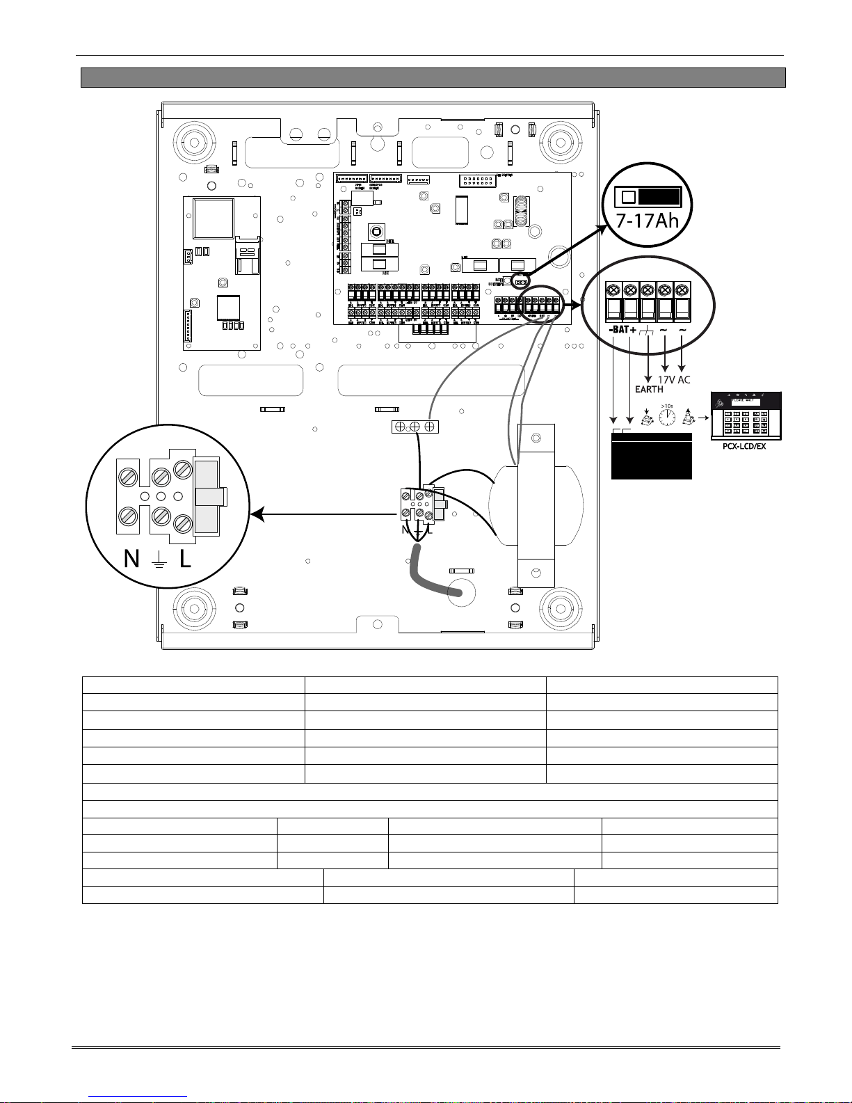
3.4 Power and Battery Connections for the PCX 46 APP L
Panel Power Supply Input Nominal Range
Mains Supply Voltage AC 230V AC at 50Hz -15% +10%
Transformer Rating PCX 46 APP L
45VA 18.5V at 2.5A
Panel Power Supply Output Nominal Range
Output Voltage 13.7V DC 10-15V DC
Output Current PCX 46 APP L
1.5A Continuous 2.0A peak, during battery charging
Power Supply Type A.
Battery Charging Specification
Float Voltage 13.8v DC Control Panel Type
Battery low voltage cut off 10.5v Standby battery capacity current 300mA (3Ah to 6Ah)
Recharge time <24 Hours Standby battery capacity current 700mA (7Ah to 17Ah)
Fuses Value Type
230V Mains Fuse for mains terminals T500mA H anti-surge slow blow 250V Ceramic
NOTE: The battery connect ‘kickstart’ button (see Item 9, page 8) is used to power-up the control panel
when there is no mains supply present. For example: if you wish to program a panel that is being fitted
in a new-build premises before the mains supply has been fully installed. To use it – Hold for 5 seconds
and then release.
IMPORTANT: Ensure that the battery Jumper is in the correct position for the capacity of battery that
you have connected – otherwise the panel may under-charge a large battery or over-charge and damage
a smaller battery.
Page 13
PCX 46 App Installation Reference
Page: 13
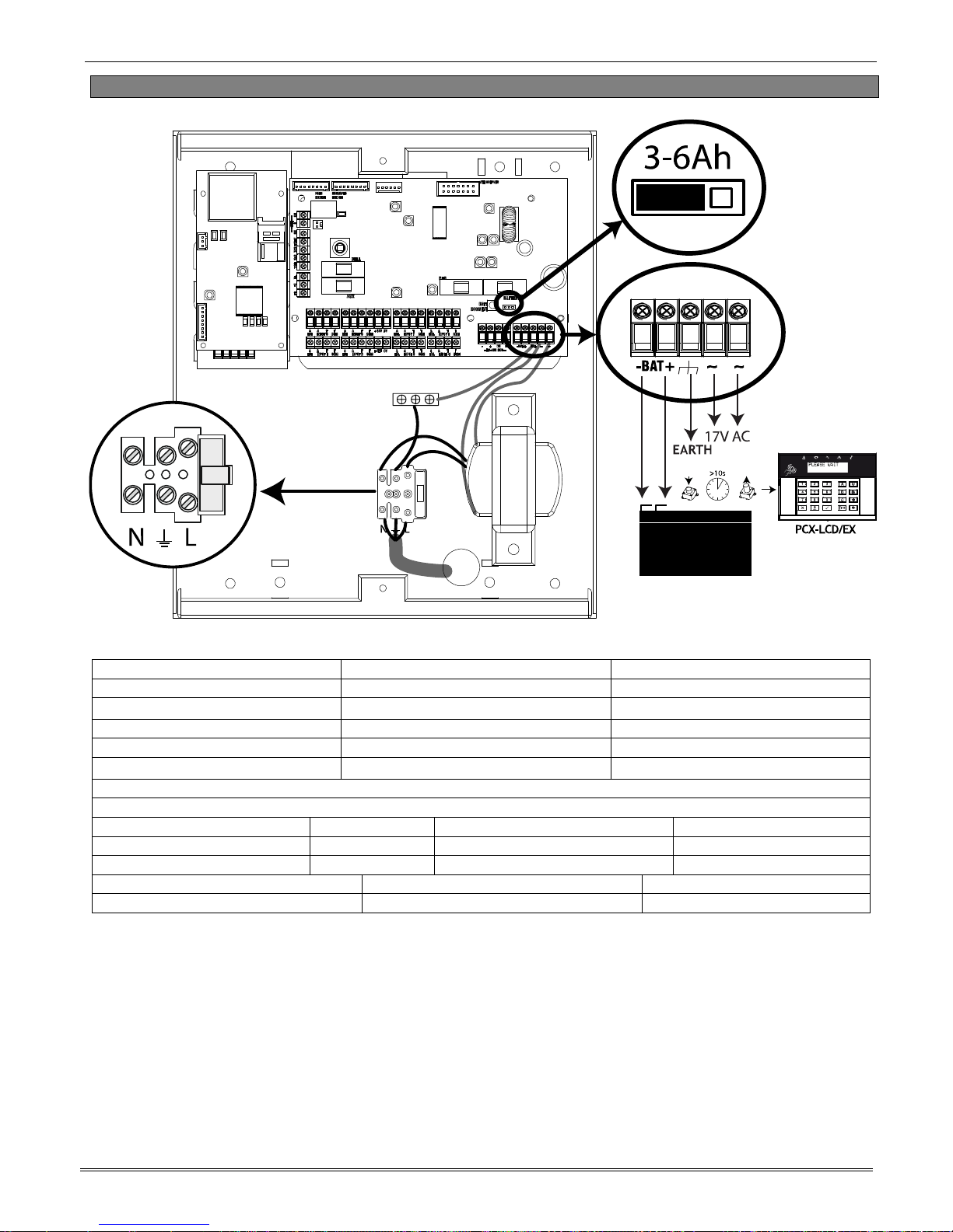
3.5 Power and Battery Connections for the PCX 46 APP S
Panel Power Supply Input Nominal Range
Mains Supply Voltage AC 230V AC at 50Hz -15% +10%
Transformer Rating PCX 46 APP S
18VA 18V at 1.0A
Panel Power Supply Output Nominal Range
Output Voltage 13.7V DC 10-15V DC
Output Current PCX 46 APP S
1A Continuous 1.5A peak, during battery charging
Power Supply Type A.
Battery Charging Specification
Float Voltage 13.8v DC Control Panel Type
Battery low voltage cut off 10.5v Standby battery capacity current 300mA (3Ah to 6Ah)
Recharge time <24 Hours Standby battery capacity current 700mA (7Ah to 17Ah)
Fuses Value Type
230V Mains Fuse for mains terminals T500mA H anti-surge slow blow 250V Ceramic
NOTE: The battery connect ‘kickstart’ button (see Item 9, page 8) is used to power-up the control panel
when there is no mains supply present. For example: if you wish to program a panel that is being fitted
in a new-build premises before the mains supply has been fully installed. To use it – Hold for 5 seconds
and then release.
IMPORTANT: Ensure that the battery Jumper is in the correct position for the capacity of battery that
you have connected – otherwise the panel may under-charge a large battery or over-charge and damage
a smaller battery.
Page 14
PCX 46 App Installation Reference
Page: 14
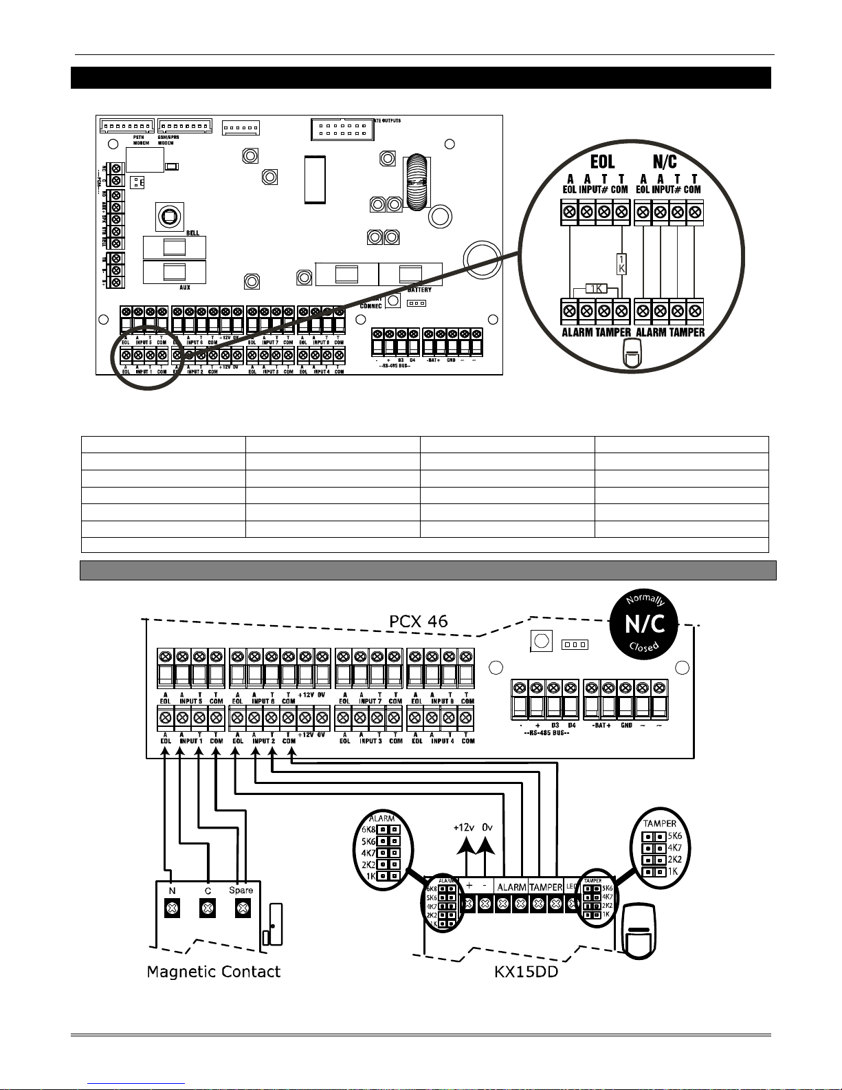
4. Input Connections
NOTE: If ‘Normally Closed’ (double pole) wiring is selected, the Diagnostics on the keypad will show "4K
Alarm and 2K2 Tamper".
Input Resistance 1k / 1k DEOL Range 4k7 / 2k2 DEOL Range 4k7 / 4k7 DEOL Range
Normal 0k5 to 1k4 1k4 to 2k9 3k7 to 8k3
Burglary Alarm 1k5 to 5k9 4k2 to 7k8 8k4 to 10k2
Fault 6k to 8k1 8k to 11k3 10k3 to 14k9
Masking (6k8) 8k2 to 17k 11k6 to 22k 15k to 22k
Tamper <0k5 or <17k <1k4 or >22k <3k7 or >23k
All inputs are programmed in "PROGRAM INPUTS" in the Engineer menu.
4.1 Normally Closed Input Wiring
Page 15

PCX 46 App Installation Reference
Page: 15
4.2 Grade 2 DEOL (Double End of Line) Input Wiring
Input Resistance 1k / 1k DEOL Range 4k7 / 2k2 DEOL Range 4k7 / 4k7 DEOL Range
Normal 0k5 to 1k4 1k4 to 2k9 3k7 to 8k3
Burglary Alarm 1k5 to 5k9 4k2 to 7k8 8k4 to 10k2
Tamper <0k5 or <17k <1k4 or >22k <3k7 or >23k
4.3 Grade 3 Mask/Fault Input Wiring
Input Resistance 1k / 1k DEOL Range 4k7 / 2k2 DEOL Range 4k7 / 4k7 DEOL Range
Normal 0k5 to 1k4 1k4 to 2k9 3k7 to 8k3
Burglary Alarm 1k5 to 5k9 4k2 to 7k8 8k4 to 10k2
Fault 6k to 8k1 8k to 11k3 10k3 to 14k9
Masking (6k8) 8k2 to 17k 11k6 to 22k 15k to 22k
Tamper <0k5 or <17k <1k4 or >22k <3k7 or >23k
All inputs are programmed in "PROGRAM INPUTS" in the Engineer menu.
Page 16
PCX 46 App Installation Reference
Page: 16
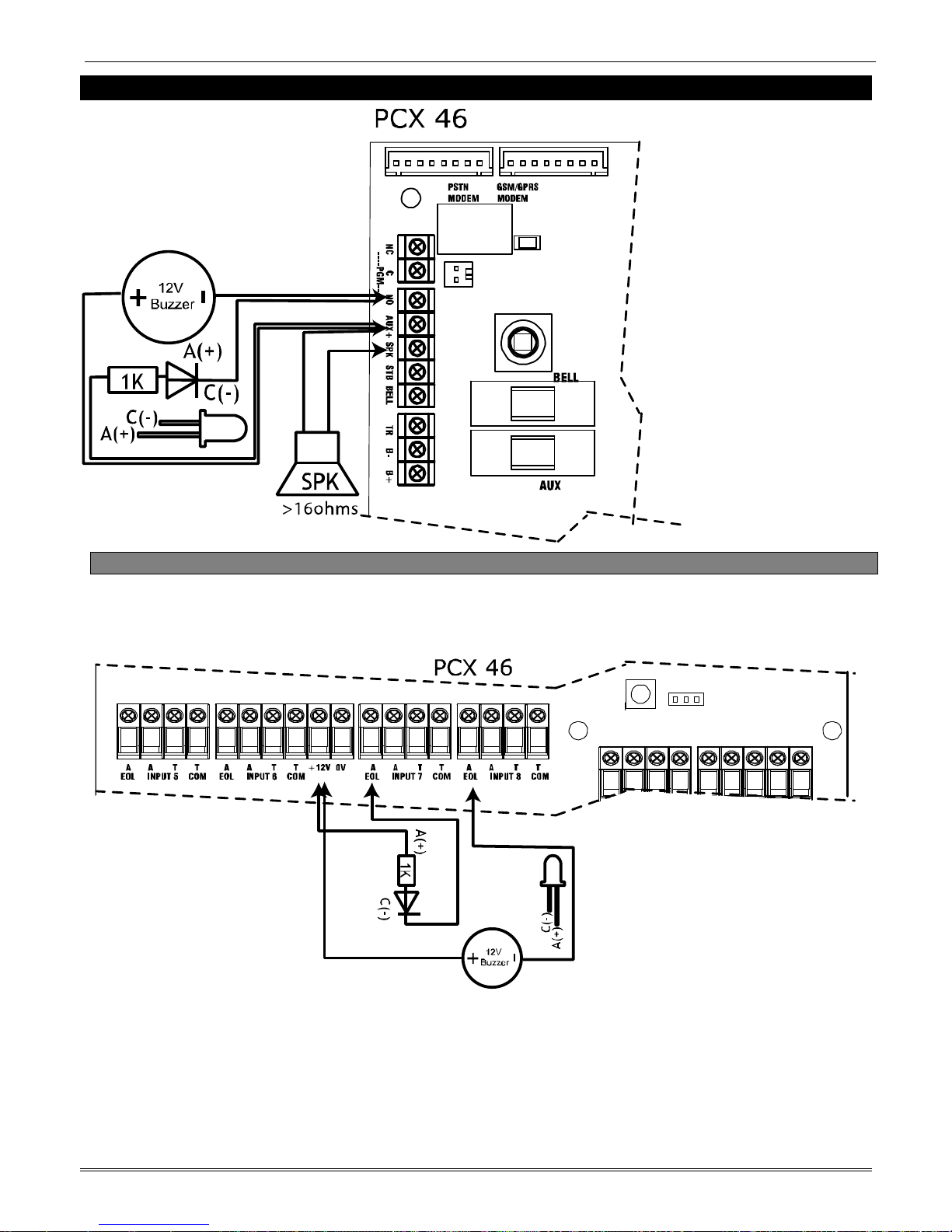
5. Output (PGM) Connections
5.1 XPGM Connections
If Inputs 7 and 8 are programmed as ‘unused’, these inputs can be used as 2 further outputs (known as
XPGM1 and XPGM2 which can be programmed in ‘PROGRAM OUTPUTS’).
Normal State: 12V
Active State: 0V
Current: 100mA
Normal State: Floating
Active State: 0V
Current: 50mA switched
to 0V
Page 17

PCX 46 App Installation Reference
Page: 17
6. External Sounder Connections
6.1 Grade 3 External Sounder Wiring
6.2 Grade 2 External Sounder Wiring with a Grade 3 Bell
Pyronix Grade 3 External Sounders: Deltabell Plus, Deltabell X, Invincibell Plus, Invincibell X
P
y
ronix Grade 3 External Sounders: Deltabell Plus, Deltabell X, Invincibell Plus, Invincibell X
Page 18

PCX 46 App Installation Reference
Page: 18
6.3 Grade 2 External Sounder Wiring
Pyronix Grade 2 External Sounders: Deltabell E, Invincibell E
Page 19

PCX 46 App Installation Reference
Page: 19
7. Connecting the PCX Peripherals
7.1 Connecting The PCX-LCD Keypad (PCX-LCD/EX)
The PCX LCD keypad is used for programming
and user operation.
The PCX 46 APP can have up to 6 x PCX-LCD/EX
keypads installed.
NOTE: See the keypad installation manual for
the LED and button explanations.
NOTE: The total number of keypads and readers
that can be installed on the PCX 46 APP is 6.
7.1.1 Technical Specification
PCX-LCD/EX (LCD Keypad)
Supply Voltage: 9-15V DC
Current Consumption: <50mA
Inputs 1 & 2 Programmable, DEOL, SEOL, 3 Resistor
Input EOL Resistor Values 1k / 1k DEOL Range 4k7 / 2k2 DEOL Range 4k7 / 4k7 DEOL Range
Normal 0k5 to 1k4 1k4 to 2k9 3k7 to 8k3
Burglary Alarm 1k5 to 5k9 4k2 to 7k8 8k4 to 10k2
Fault 6k to 8k1 8k to 11k3 10k3 to 14k9
Masking (6k8) 8k2 to 17k 11k6 to 22k 15k to 22k
PGM: 100mA
PGM Normal State: Floating
PGM Active State: 0V
Dimensions: 144 x 99 x 34mm
EN50131 Certified: Grade 3
Colour and Casing: White 3mm ABS
Indication: LEDs (OK, Fault, Alarm, Disarmed, Tamper)
NOTE: The LCD display may not function correctly at temperatures
below +2ºC but this will not affect the system operation.
Temperature Storage: -10°C to +40°C
Certified: -10°C to +40°C
Nominal: -10°C to +40°C
Front and rear tamper protected
7.1.2 Addressing The PCX LCD Keypad (From the Keypad)
Addressing
Hold the d key for more than 5 seconds.
'SECURITY CODE' will be displayed. Enter '2000'
The default address given is '00'.
Page 20

PCX 46 App Installation Reference
Page: 20
Enter the required Address [0-6] and press t Press
a to exit. You must now address is from the menu
"INSTALL KEYPADS/READERS".
7.1.3 Adding The PCX LCD Keypad (From the Engineer Menu)
Enter the engineers menu and scroll to 'INSTALL KEYPADS/READERS' and press t. Please see the
Programming Manual for more information.
7.1.4 Connecting The PCX LCD Keypad Inputs (Grade 3)
The same connections are used when wiring the TMD or XD Grade 3 detectors
Input Resistance 1k / 1k DEOL Range 4k7 / 2k2 DEOL Range 4k7 / 4k7 DEOL Range
Normal 0k5 to 1k4 1k4 to 2k9 3k7 to 8k3
Burglary Alarm 1k5 to 5k9 4k2 to 7k8 8k4 to 10k2
Fault 6k to 8k1 8k to 11k3 10k3 to 14k9
Masking (6k8) 8k2 to 17k 11k6 to 22k 15k to 22k
Tamper <0k5 or >17K <1k4 or >22k <3k7 or >23k
Page 21

PCX 46 App Installation Reference
Page: 21
7.1.5 Connecting The PCX LCD Keypad Inputs (Grade 2)
Input Resistance 1k / 1k DEOL Range 4k7 / 2k2 DEOL Range 4k7 / 4k7 DEOL Range
Normal 0k5 to 1k4 1k4 to 2k9 3k7 to 8k3
Burglary Alarm 1k5 to 5k9 4k2 to 7k8 8k4 to 10k2
Fault 6k to 8k1 8k to 11k3 10k3 to 14k9
Masking (6k8) 8k2 to 17k 11k6 to 22k 15k to 22k
Tamper <0k5 or >17K <1k4 or >22k <3k7 or >23k
7.1.6 Connecting The Outputs
Normal State: 12V
Active State: 0V
Current : 100mA
Page 22

PCX 46 App Installation Reference
Page: 22
7.2 Connecting The Internal Tag Reader (PCX-PROX/INT)
The Internal Tag Reader can have 2 inputs connected. It can
be used as an arm, disarm, entry control or an access
control device.
NOTE: See the reader installation manual for the LED and
button explanations.
NOTE: The total number of readers that can be installed on
the PCX 46 APP is 5. The readers are installed on the same
bus as the keypads.
7.2.1 Technical Specification
PCX-PROX/INT (Internal Tag Reader)
Input Voltage: 12VDC (9-15V DC range)
Supply Current: <30mA Quiescent. <90mA Maximum
Inputs: Programmable. 2 inputs; DEOL
Input EOL Fixed Resistor
Values:
Alarm=4K7 / Tamper=2K2
Normal: 1k4 to 2k9
Burglary Alarm:4k2 to 7k8
Tamper: <1k4 or >22k
Shared Outputs: Switched negative 150mA (Max)
Colour and Casing: White 3mm ABS
Indication: LEDs (Alert, Alarm, Fault, Tamper, Disarmed)
Temperature: Storage:-20°C to 60°C
Certified: -10°C to 40°C
Nominal: -20°C to 60°C
Dimensions (H x W x D): 97 x 40 x 23mm
Front and rear tamper protected
NOTE: If the PCX-PROX/INT (Internal Tag Reader) is programmed as an 'Arm/Disarm' device, 2 inputs
are enabled. If the PCX-PROX/INT is programmed as 'Entry Control' or 'Access Control' only 1 input is
enabled.
7.2.2 Addressing The Internal Tag Reader (From the Reader)
Page 23

PCX 46 App Installation Reference
Page: 23
7.2.3 Adding The Internal Tag Reader (From the Engineer Menu)
Enter the engineers menu and scroll to 'INSTALL KEYPADS/READERS' and press t. Please see the
Programming Manual for more information.
7.2.4 Connecting The Internal Tag Reader Inputs
7.2.5 Using the Internal Tag Reader as Access Control/Entry Control
Normal State: 12V
Active State: 0V
Current : 150mA
NOTE: The resistance values are fixed to 4K7
Alarm and 2K2 Tamper in the PCX-PROX/INT
Reader
Input Resistance:
4k7 / 2k2 DEOL Range
Normal: 1k4 to 2k9
Burglary Alarm:4k2 to 7k8
Tamper: <1k4 or >22k
Page 24

PCX 46 App Installation Reference
Page: 24
7.3 Connecting The External Proximity Reader (PCX-EXT-BK)
The External Proximity Reader can be used as either an arm,
disarm, entry control or an access control device.
NOTE: See the reader installation manual for the LED and
button explanations.
NOTE: The total number of readers that can be installed on
the PCX 46 APP is 5. The readers are installed on the same
bus as the keypads.
7.3.1 Technical Specification
PCX-EXT-BK / W (External Tag Reader)
Supply voltage: 9-15VDC
Current consumption: Max 22mA
Input status when reader is Arm/Disarm or Sub-Area Control:
Input: Programmable. DEOL
Input EOL fixed resistor
value:
Alarm=4K7 / Tamper=2K2
Normal: 1k4 to 2k9
Burglary Alarm:4k2 to 7k8
Tamper: <1k4 or >22k
Input status when reader is used as Access or Door Entry Control:
Input 1: Programmable
Input Function: Door monitor feature. Door opening time limit is programmable from the
Engineer Menu
Input 2: Not programmable
Note: Access control falls outside the scope of EN 50131
Output 1: Not program m able. Activates the Door Lock Relay
Output 2: Not program mable. Door monitor alarm activation (forced or open for longer
than programmed time).
Output 1/2 Normal state: Floating
Output 1/2 Active state: 0V
Colour and Casing: 3mm ABS (Black: PCX-EXT-BK, White: PCX-EXT-W)
Potted Type B
Temperatures: Storage: -10°C to 50°C
Certified: -25°C to 60°C
Nominal: -25°C to 60°C
Dimensions (H x W x D): 85 x 85 x 21mm
IP65 Rated. If the control panel fails to arm, this is indicated by a broken tone on the external
proximity reader and the red LED will not illuminate. If this occurs, please check the
information at the nearest keypad.
7.3.2 Addressing the External Tag Reader (From the Reader)
Page 25

PCX 46 App Installation Reference
Page: 25
7.3.3 Adding the External Tag Reader (From the Engineer Menu)
Enter the engineers menu and scroll to 'INSTALL KEYPADS/READERS' and press t. Please see the
Programming Manual for more information.
7.3.4 Connecting a Mag Lock and a Request to Exit Button to the External Tag Reader
The diagram show the relay mag lock control switching positive and shows a normally open request to
exit button, and takes “0V” from the control panel.
7.3.5 Connecting Door Monitoring and Door Alarm Monitoring to the External Tag Reader
Connecting Door Monitoring: Use the white and grey wire. The door monitor input needs to be
programmed as the first input number of the reader address (programmed as “Entry Delay”). If the
door contact is forced open without presenting a valid tag or pressing the push to exit button, then
the panel will go into an alarm. NOTE: The DEOL values must be 4K7, 2K2 as shown. This does not
affect the control panel DEOL values.
Connecting Door Alarm Monitoring: Use the purple wire. When the door monitor exceeds the door
open time or if the door is forced open then the alarm PGM will generate an alarm. The input at the
control panel should be programmed as “24 Hour” and the attribute programmed as “Normally Open”.
Please see the next page for the wiring diagrams.
Input Resistance:
4k7 / 2k2 DEOL Range
Normal: 1k4 to 2k9
Burglary Alarm: 4k2 to 7k8
Tamper: <1k4 or >22k
NOTE: The resistance values are
fixed to 4K7 Alarm and 2K2
Tamper in the PCX-EXT-BK/W
Reader.
Page 26

PCX 46 App Installation Reference
Page: 26
7.3.6 Using the External Tag Reader for Arming and Entry Control
7.3.7 Using the Request to Exit button
7.3.8 Using the External Tag Reader Disarming
Page 27

PCX 46 App Installation Reference
Page: 27
7.1 Connecting The PCX-RIX8i (Remote Input Expander with Inertia)
7.1.1 The PCX-RIX8i Expander
PCX-RIX8i
The PCX-RIX8i is an input expander that
supports 8 normal or inertia inputs (also
known as fast inputs).
It also supports NC (normally closed), DEOL
and SEOL input wiring.
The PCX 46 will support up to 4 x Remote
Inputs Expanders.
7.1.2 PCX-RIX8i Technical Specification
PCX-RIX8i (Inertia Input Expander)
Input Voltage 9-15V
Current Consumption 45mA
Inputs DEOL, NC, Inertia (Fast inputs)
Input EOL Fixed Resistor
Values
1k / 1k DEOL Range
Normal: 0k5 to 1k4
Burglary Alarm: 1k5 to 5k9
Tamper: <0k5 or >17K
Dimensions (plastic box) 173 x 125 x 32mm
Dimensions (PCB) 128 x 87 x 16mm
Colour and Casing White 3mm ABS with clear polycarbonate window
Grade 2 Indication LEDs (Power, OK and Fault)
Temperature Storage: -20°C to +60°C
Certified: -10°C to +40°C
Nominal: -10°C to +50°C
Front and rear tamper protected
NOTE: This product is only compliant to Security Grade 2
7.1.3 Addressing The PCX-RIX8i (From The Expander)
Input Resistance:
1k / 1k DEOL Range
Normal: 0k5 to 1k4
Burglary Alarm: 1k5 to 5k9
Tamper: <0k5 or >17k
NOTE: The resistance values
are fixed to 1K Alarm and 1K
Tamper on the PCX-RIX8i
expander.
Page 28

PCX 46 App Installation Reference
Page: 28
7.1.4 Addressing the PCX-RIX8i (From The Expander)
7.1.5 Adding the PCX-RIX8i (From the Engineer Menu)
Enter the Engineers menu and scroll to 'INSTALL RIX' and press t. Please see the Programming
Manual for more information.
7.1.6 Wiring Inputs on the PCX-RIX8i (Normally Closed)
Page 29

PCX 46 App Installation Reference
Page: 29
7.1.7 Wiring Inputs on the PCX-RIX8i (DEOL: Grade 2)
NOTE: The resistance values are fixed to 1K Alarm and 1K Tamper
on the PCX-RIX8i expander.
7.1.8 Wiring Fast Inputs on the PCX-RIX8i (Normally Closed)
Connecting a Roller Shutter Connecting a Shock Sensor
NOTE: The programming menu "PROGRAM INPUTS" has a sub-menu called 'Input Attributes'. This has an
option to enable or disable Inertia inputs.
Input Resistance:
1k / 1k DEOL Range
Normal: 0k5 to 1k4
Burglary Alarm:1k5 to 5k9
Tamper: <0k5 or <17k
Page 30

PCX 46 App Installation Reference
Page: 30
7.1.9 Wiring Fast Inputs on the PCX-RIX8i (DEOL: Grade 2)
Connecting a Roller Shutter Connecting a Shock Sensor
NOTE: These resistances are fixed to 1K Alarm and 1K Tamper and
cannot change.
NOTE: The programming menu "PROGRAM INPUTS" has a sub-
menu called 'Input Attributes'. This has an option to enable or
disable Inertia inputs.
Input Resistance:
1k / 1k DEOL Range
Normal: 0k5 to 1k4
Burglary Alarm: 1k5 to 5k9
Tamper: <0k5 or >17k
Page 31

PCX 46 App Installation Reference
Page: 31
7.2 Connecting The PCX-RIX8+ (Remote Input Expander with 4 PGMs)
PCX-RIX8+
The PCX-RIX8+ is an input expander that
supports 8 inputs (not inertia).
It also supports normally closed (double pole),
DEOL and SEOL input wiring.
There are 4 programmable PGMs.
The PCX 46 will support up to 4 x Remote
Input Expanders.
7.2.1 PCX-RIX8+ Technical Specification
PCX-RIX8+ (Input Expander)
Input Voltage 9-15V
Current Consumption 30mA
Inputs Programmable
DEOL, NC, 3 Resistor (Grade 3)
Input EOL Resistor
Values
1k / 1k DEOL Range 4k7 / 2k2 DE OL Range 4k7 / 4k7 DEOL Range
Normal 0k5 to 1k4 1k4 to 2k9 3k7 to 8k3
Burglary Alarm 1k5 to 5k9 4k2 to 7k8 8k4 to 10k2
Fault 6k to 8k1 8k to 11k3 10k3 to 14k9
Masking (6k8) 8k2 to 17k 11k6 to 22k 15k to 22k
PGM1 - PGM4 100mA each
PGM1 - PGM4 Normal state: 12V
PGM1 - PGM4 Active state: 0V
Dimensions (plastic
box)
173 x 125 x 32mm
Dimensions (PCB) 128 x 87 x 16mm
Colour and Casing White 3mm ABS with clear polycarbonate window
Indication LEDs (Power, OK and Fault)
Temperature Storage: -20°C to +60°C
Certified: -10°C to +40°C
Nominal: -10°C to +50°C
Front and rear tamper protected
Page 32

PCX 46 App Installation Reference
Page: 32
7.2.2 PCX-RIX8+ Input Configuration
7.2.3 Addressing the PCX-RIX8+
7.2.4 Adding the PCX-RIX8+ (From the Engineer Menu)
Enter the engineers menu and scroll to 'INSTALL RIX' and press t. Please see the Programming
Manual for more information.
Input
Resistance
1k / 1k DEOL
Range
4k7 / 2k2 DEOL
Range
4k7 / 4k7 DEOL
Range
Normal 0k5 to 1k4 1k4 to 2k9 3k7 to 8k3
Burglary Alarm 1k5 to 5k9 4k2 to 7k8 8k4 to 10k2
Fault 6k to 8k1 8k to 11k3 10k3 to 14k9
Masking (6k8) 8k2 to 17k 11k6 to 22k 15k to 22k
Tamper <0k5 or >17K <1k4 or >22k <3k7 or >23k
Page 33

PCX 46 App Installation Reference
Page: 33
7.2.5 Wiring Inputs on the PCX-RIX8+ (Normally Closed)
Input Resistance 1k / 1k DEOL Range 4k7 / 2k2 DEOL Range 4k7 / 4k7 DEOL Range
Normal 0k5 to 1k4 1k4 to 2k9 3k7 to 8k3
Burglary Alarm 1k5 to 5k9 4k2 to 7k8 8k4 to 10k2
Tamper <0k5 or >17K <1k4 or >22k <3k7 or >23k
All inputs are programmed in "PROGRAM INPUTS" in the Engineer menu.
7.2.6 Wiring Inputs on the PCX-RIX8+ (DEOL - Grade 2)
Input Resistance 1k / 1k DEOL Range 4k7 / 2k2 DEOL Range 4k7 / 4k7 DEOL Range
Normal 0k5 to 1k4 1k4 to 2k9 3k7 to 8k3
Burglary Alarm 1k5 to 5k9 4k2 to 7k8 8k4 to 10k2
Tamper <0k5 or <17k <1k4 or >22k <3k7 or >23k
All inputs are programmed in "PROGRAM INPUTS" in the Engineer menu.
Page 34

PCX 46 App Installation Reference
Page: 34
7.2.7 Wiring Inputs on the PCX-RIX8+ (DEOL - Grade 3)
Input Resistance 1k / 1k DEOL Range 4k7 / 2k2 DEOL Range 4k7 / 4k7 DEOL Range
Normal 0k5 to 1k4 1k4 to 2k9 3k7 to 8k3
Burglary Alarm 1k5 to 5k9 4k2 to 7k8 8k4 to 10k2
Fault 6k to 8k1 8k to 11k3 10k3 to 14k9
Masking (6k8) 8k2 to 17k 11k6 to 22k 15k to 22k
Tamper <0k5 or <17k <1k4 or >22k <3k7 or >23k
All inputs are programmed in "PROGRAM INPUTS" in the Engineer menu.
7.2.8 Output Wiring on the PCX-RIX8+
Normal State: 12V
Active State: 0V
Current: 100mA
Page 35

PCX 46 App Installation Reference
Page: 35
7.3 Connecting The PCX-RIX8+PSU (Remote Input Expander with PSU)
PCX-RIX8+PSU
The PCX-RIX8+ is an input expander
that supports 8 inputs (not inertia)
and has a 2.5A power supply.
It supports normally closed (N/C),
DEOL and 3EOL input wiring.
The PCX 46 will support up to 4 x
Remote Input Expanders.
NOTE: The D2+ terminal should
not be connected.
7.3.1 PCX-RIX8+PSU Technical Specification
PCX-RIX8+PSU (Input Expander with Power Supply)
Input Voltage 9-15V
Current Consumption 65mA
Inputs Programmable
DEOL, N/C, 3 Resistor (Grade 3)
Input EOL Resistor Values
1k / 1k DEOL Range 4k7 / 2k2 DE OL Range 4k7 / 4k7 DEOL Range
Normal 0k5 to 1k4 1k4 to 2k9 3k7 to 8k3
Burglary Alarm 1k5 to 5k9 4k2 to 7k8 8k4 to 10k2
Fault 6k to 8k1 8k to 11k3 10k3 to 14k9
Masking (6k8) 8k2 to 17k 11k6 to 22k 15k to 22k
PGM1 - PGM4 100mA each
PGM1 - PGM4 Normal state: 12V
PGM1 - PGM4 Active state: 0V
Power Supply Rating 2.0A continued and 2.5A in peak when charging battery
Transformer Rating 44VA
Dimensions (metal box) 390 x 305 x 100mm
Dimensions (PCB) 215 x 125 x 65mm
Colour and Casing White metal casing
Indication LEDs (Power, RS485 In, A-Fault, RS485 Out, P-Fault)
Temperature Storage: -20°C to +60°C
Certified: -10°C to +40°C
Nominal: -10°C to +50°C
EN50131 Certified Grade 3
Front and rear tamper protected with one tamper switch
PD6662:2010 Installations – Back up battery time = 12hrs providing that a mains fail signal is
reported to the ARC.
A 17Ah battery, will support a maximum load of 1350mA for a period of 12 hours.
EN50131-1:2006+A1:2009 Installations - Back up battery time = 30hrs providing that a mains fail
signal is reported to the ARC.
A 17Ah battery, will support a maximum load of 497mA for a period of 30 hours. Installations which
are not supported by an ARC mains fail reported signal = 60 hours. A 17Ah battery, will support a
maximum load of 248mA for a period of 60 hours.
Page 36

PCX 46 App Installation Reference
Page: 36
7.3.2 PCX-RIX8+PSU Input Configuration
Input Resistance 1k / 1k DEOL Range 4k7 / 2k2 DEOL Range 4k7 / 4k7 DEOL Range
Normal 0k5 to 1k4 1k4 to 2k9 3k7 to 8k3
Burglary Alarm 1k5 to 5k9 4k2 to 7k8 8k4 to 10k2
Fault 6k to 8k1 8k to 11k3 10k3 to 14k9
Masking (6k8) 8k2 to 17k 11k6 to 22k 15k to 22k
Tamper <0k5 or >17K <1k4 or >22k <3k7 or >23k
All inputs are programmed in "PROGRAM INPUTS" in the Engineer menu.
7.3.3 Addressing the PCX-RIX8+PSU
7.3.4 Adding the PCX-RIX8+PSU (From the Engineer Menu)
Enter the Engineers menu and scroll to 'INSTALL RIX' and press t. Please see the Programming
Manual for more information.
Page 37

PCX 46 App Installation Reference
Page: 37
7.3.5 Wiring Inputs on the PCX-RIX8+PSU (Normally Closed)
Input Resistance 1k / 1k DEOL Range 4k7 / 2k2 DEOL Range 4k7 / 4k7 DEOL Range
Normal 0k5 to 1k4 1k4 to 2k9 3k7 to 8k3
Burglary Alarm 1k5 to 5k9 4k2 to 7k8 8k4 to 10k2
Tamper <0k5 or >17K <1k4 or >22k <3k7 or >23k
All inputs are programmed in "PROGRAM INPUTS" in the Engineer menu.
7.3.6 Wiring Inputs on the PCX-RIX8+PSU (DEOL: Grade 2)
Input Resistance 1k / 1k DEOL Range 4k7 / 2k2 DEOL Range 4k7 / 4k7 DEOL Range
Normal 0k5 to 1k4 1k4 to 2k9 3k7 to 8k3
Burglary Alarm 1k5 to 5k9 4k2 to 7k8 8k4 to 10k2
Tamper <0k5 or >17K <1k4 or >22k <3k7 or >23k
All inputs are programmed in "PROGRAM INPUTS" in the Engineer menu.
Page 38

PCX 46 App Installation Reference
Page: 38
7.3.7 Wiring Inputs on the PCX-RIX8+PSU (DEOL: Grade 3)
Input Resistance 1k / 1k DEOL Range 4k7 / 2k2 DEOL Range 4k7 / 4k7 DEOL Range
Normal 0k5 to 1k4 1k4 to 2k9 3k7 to 8k3
Burglary Alarm 1k5 to 5k9 4k2 to 7k8 8k4 to 10k2
Fault 6k to 8k1 8k to 11k3 10k3 to 14k9
Masking (6k8) 8k2 to 17k 11k6 to 22k 15k to 22k
Tamper <0k5 or >17K <1k4 or >22k <3k7 or >23k
All inputs are programmed in "PROGRAM INPUTS" in the Engineer menu.
7.3.8 Output Wiring on the PCX-RIX8+PSU
Normal State: 12V
Active State: 0V
Current : 100mA
Page 39

PCX 46 App Installation Reference
Page: 39
7.4 Connecting The PCX-RIX32-WE (Remote Wireless Expander)
PCX-RIX32-WE
The PCX-RIX32-WE is a input
expander that supports Two Way
wireless Enforcer technology. It will
allow 32 wireless inputs, 32 wireless
keyfobs and 2 wireless bells to be
learnt and programmed on the PCX 46
APP system.
The PCX 46 APP will support only 1 x
PCX-RIX32-WE.
7.4.1 PCX-RIX32-WE Technical Specification
PCX-RIX32-WE (Two Way Wireless Input Expander)
Input Voltage 9-14V
Current Consumption 60mA quiescent
115mA during transmission
Radio Frequency 868MHz FM Transceiver Narrow Band. Range: 1.6km
Dimensions (metal box) 173 x 125 x 32mm
Colour and Casing White plastic casing
Indication LEDs (Power and Data)
Temperature Operational: -10°C to +50°C
Certified: -10°C to +40°C
Storage: -40°C to +80°C
Humidity 85% @ 25°C
Weight 0.24kg
7.4.2 Addressing the PCX-RIX32-WE (From the Expander)
The PCX 46 APP will support both wired and wireless expanders on the same bus. Wireless sounders and
keyfobs must be learned to Address 0.
NOTE: Please make sure that you address the PCX-RIX32-WE while the tamper switch is open.
The address will then be assigned when the tamper is closed.
Page 40

PCX 46 App Installation Reference
Page: 40
Addressing Example: Having 32 wireless inputs on the PCX 46 APP
PCX-RIX32-WE: DEVICE A
This expander will learn all 32 wireless keyfobs and 2 wireless bells.
Address 0 = 8 wireless inputs (Inputs 9-16)
Address 1 = 8 wireless inputs (Inputs 17-24)
Address 2 = 8 wireless inputs (Inputs 25-32)
Address 3 = 8 wireless inputs (Inputs 33-40)
Wired expanders may also be used in conjunction with wireless expanders.
7.4.3 Adding the PCX-RIX32-WE (From the Engineer Menu)
Enter the engineers menu and scroll to 'INSTALL RIXs?' and press t. Please see the Programming
Manuals for more information.
7.4.4 Learning Wireless Devices
All wireless devices are learnt in the Engineer function ‘LEARN WIRELESS DEVICES?'. Please see the
programming manuals (for inputs and bells) and user manual (keyfobs) for more information
Page 41

PCX 46 App Installation Reference
Page: 41
7.5 Connecting The PCX-ROX8R8T (Remote Output Expander)
PCX-ROX8R8T
The PCX-ROX8R8T is an output expander that
supports 8 way relays and 8 transistor
outputs.
The PCX 46 APP will support up to 2 x Remote
Output Expanders.
7.5.1 PCX-ROX8R8T Technical Specification
PCX-ROX8R8T (Output expander with 1 6 PGMs)
Supply Voltage 9-15V DC
Current Consumption 25mA, Max 300mA when all outputs are active
PGM1 to PGM16 Programmable
PGM1 to PGM8 Type Relay, 3A, max 30V
PGM1 to PGM8 Normal State Changeover NC & NO
PGM1 to PGM4 Active State Changeover NC & NO
PGM9 to PGM16 Type Open Collector
PGM9 to PGM16 Normal State Floating
PGM9 to PGM16 Active State 0V
Dimensions Plastic Box 173 x 125 x 32mm
Dimensions PCB 135 x 90 x 15mm
EN50131 Certified Grade 3
7.5.2 Addressing The PCX-ROX8R8T (From the Expander)
7.5.3 Adding The PCX-ROX8R8T (From the Engineer Menu)
Enter the engineers menu and scroll to 'PROGRAM OUTPUTS' and then 'O/P Module O/Ps?' and press
t. Please see the Programming Manuals for more information.
Page 42

PCX 46 App Installation Reference
Page: 42
7.5.4 PCX-ROX8R8T Output Connections
Page 43

PCX 46 App Installation Reference
Page: 43
7.6 Connecting The PCX-ROX16R+PSU Expander (Remote Output Expander with PSU)
PCX-ROX16R+PSU
The PCX-ROX16R+PSU is an output
expander that supports 16 way relays and
has a 2.5A power supply.
The PCX 46 APP will support up to 2
x Remote Output Expanders.
NOTE: The D2+ terminal MUST not be
connected.
7.6.1 PCX-ROX16R+PSU Technical Specification
PCX-ROX16R/PSU (Output expander with 16 PGMs and Power Supply)
Supply Voltage 9-15V DC
Current Consumption 25mA, Max 340mA when all outputs are active
PGM1 to PGM16 Programmable
PGM1 to PGM16 Type Relay, 3A, max 30V
PGM1 to PGM16 Normal State Changeover NC & NO
PGM1 to PGM16 Active State Changeover NC & NO
Power Supply Rating 2.0A Continued and 2.5A in peak when charging battery
Transformer Rating 44VA
Dimensions Metal Box 390 x 205 x 100mm
Dimensions PCB 215 x 125 x 65mm
Front and rear tamper protected with one tamper switch
Front and rear tamper protected with one tamper switch
A 17Ah battery, will support a maximum load of 1350mA for a period of 12 hours.
EN50131-1:2006+A1:2009 Installations - Back up battery time = 30hrs providing that a mains fail
signal is reported to the ARC.
A 17Ah battery, will support a maximum load of 497mA for a period of 30 hours.
Installations which are not supported by an ARC mains fail reported signal = 60 hours.
A 17Ah battery, will support a maximum load of 248mA for a period of 60 hours.
EN50131 Certified Grade 3
7.6.2 Addressing The PCX-ROX16R+PSU (From the Expander)
Page 44

PCX 46 App Installation Reference
Page: 44
7.6.3 Adding The PCX-ROX16R+PSU (From the Engineer Menu)
Enter the engineers menu and scroll to 'PROGRAM OUTPUTS' and then 'O/P Module O/Ps?' and press
t. Please see the Programming Manuals for more information.
7.6.4 PCX-ROX16R+PSU Connections
Page 45

PCX 46 App Installation Reference
Page: 45
8. The GPRS, LAN and PSTN Modems
Connecting the modems in the large box Connecting the modems in the small box
The PSTN modem should be located underneath the
PCX 46 APP PCB and the GPRS or LAN modems should
be located to the left of the PCX 46 APP PCB.
The PSTN modem should be located at the
bottom (closest to the base) and the GPRS or
LAN modems should be located at the top.
GPRS or LAN Modem
PSTN Modem
GPRS or LAN Modem
PSTN Modem
Page 46

PCX 46 App Installation Reference
Page: 46
Connecting the modems to the control panel
8.1 The PSTN Modem (Digi-1200)
The PSTN DIGI-1200 card is a fast modem and enables communication via PSTN
line using Contact ID and SIA Level 1/ Level 3 as well as remote uploading/
downloading.
A = Telephone line output for connection to analogue PSTN telephone line
B = Telephone line output for connection to analogue PSTN telephone line
A-1 = Telephone line output for connection to internal telecom equipmen t
B-1 = Telephone line output for connection to internal telecom equipment
Before making these connections, all power must be disconnected from the system.
NOTE: The ground terminal should ALWAYS be connected to earth in order to
increase the effectiveness of the transient voltage protection on the unit.
IMPORTANT NOTE: POWER DOWN THE PCX 46 BEFORE DISCONNECTING THE
MODEM.
Page 47

PCX 46 App Installation Reference
Page: 47
8.2 The GPRS Modem (DIGI-GPRS)
The GPRS modem card (DIGI-GPRS) fits inside the PCX 46 APP. Besides
communications with the PyronixCloud and
HomeControl+ App, it has the
following operations:
Send Alarms to the ARC:
With the DIGI-GPRS it is possible to send alarm events the monitoring station
via Contact ID IP an SIA IP protocols.
Send SMS Alarms to the user:
With DIGI-GPRS it is possible to send SMS alarm messages to the user.
Programming the panel remotely via the GPRS network:
With the DIGI-GPRS is also possible to program the PCX 46 APP remotely. In
order to be able to use this feature it is necessary that the CSD data channel for
the SIM card used in the modem is activated. We recommend consulting with
the GPRS service providers for the availability of the CSD services on their
networks.
Fault Detection
Minimum time for the detection of a GPRS fault signal is 2 minutes, 30 seconds.
GPRS Status LEDs
Antenna
The supplied antenna will need to be connected to the PCX
46 APP GPRS and placed in a suitable area where the signal
strength is to its maximum.
IMPORTANT NOTE: REMOVE THE POWER SUPPLY OF THE DIGI-GPRS MODEM FROM PANEL WHEN
INSTALLING OR CHANGING THE SIM. NOTE: CHECK THE SIM CARD CREDIT REGULARLY.
8.3 The LAN Modem (Digi-LAN)
The LAN modem card (DIGI-LAN) fits inside the PCX 46 APP. It allows
communications with the PyronixCloud and
HomeControl+ App via a standard
Ethernet internet connection cable and also has the following features:
Send Alarms to the ARC:
With the DIGI-LAN it is possible to send alarm events to the monitoring station
via Contact ID IP and SIA IP protocols.
Programming the panel remotely via secure network connection:
With the DIGI-LAN is also possible to program the PCX 46 APP remotely via a
secure internet connection and use of the Insite UDL software.
Status LEDs
The Digi-LAN features the industry standard Ethernet /LAN cable connection
status and activity LEDs.
Micro SD slot
(for future features in development)
Page 48

PCX 46 App Installation Reference
Page: 48
8.4 Connecting to the Upload/Download Software
The PCX 46 APP control panel can be programmed by the LCD menu or the UDL InSite Software provided
free of charge. It can be downloaded from http://www.pyronix.com/pyronix-downloads.php. The
connection between control panel and UDL software can be done in the following ways:
8.4.1 Serial Connection (RS232)
1. Enter the Engineer menu (code 9999)
2. Scroll the menu (x button) until the “Options Up/Downloading”
3. Choose RS-232 in the “Download by” option – Press t
4. Now on the ‘UDL Password’ screen – DO NOT USE – leave blank and Press t
5. Now on the ‘Site Name’ screen – this is optional – if you enter a site name, make sure that you
take a note of it for use later in the Insite software – or leave blank – then press t
6. Now on the ‘UDL Priority’ screen – we recommend setting this to High [0] (which prevents
HomeContol+ App events / notifications from disconnecting the UDL connection).
8.4.2 On InSite UDL software from a PC
1. To setup the COM port associated to “modem” open the software, click on “Configuration”, choose “Modem Settings” and select “RS-232” option
2. Make sure that the serial COM used by UDL is the set the same in the PC
(Control Panel -> Device Manager -> Ports)
3. Make sure that the UDL Graphic user interface has the RS-232 icon green colored and glowing
4. Click on “Force Dial Customer”
5. Set “Dial Mode” field to “RS-232”
6. Enter the Engineer code in the “Engineer Code” field
7. Click on “dial”
8. If connection is successful, the RS-232 icon will become blue
Page 49

PCX 46 App Installation Reference
Page: 49
8.4.3 Modem Connection DIGI-1200 (PSTN)
On the Panel: (Ensure that the panel and remote PC are connected to a suitable PSTN line).
1. Enter the Engineer Menu (code 9999)
2. Scroll the menu (x button) until the “Options Up/Downloading”
3. Choose Modem in the “Download by” option
4. Set the desired number of redials and Press t
5. Now on the ‘UDL Password’ screen – DO NOT USE – leave blank and Press t
6. Now on the ‘Site Name’ screen – this is optional – if you enter a site name, make sure that you
take a note of it for use later in the Insite software – or leave blank – then press t
7. Now on the ‘UDL Priority’ screen – we recommend setting this to High [0] (which prevents
HomeContol+ App events / notifications from disconnecting the UDL connection).
On InSite UDL software from a PC
1. To setup the COM port associated to “modem” open the software, click on “Configuration”, choose
“Modem Settings” and select “MODEM” option
2. Verify that COM port associated to “Modem” in the UDL is the same set in the PC
3. Verify that the modem Icon is green and glowing in the software Graphic User Interface
4. In the “Configurations” menu choose the “Modem Type” from the drop down menu. This is the
modem connected to the PC and used to call the panel
5. Press “Load Default String” to program the right initialization string for the selected modem
6. Click on “Force Dial customer”
7. Set “Dial Mode” field to “MODEM” and insert the telephone number in “Telephone Number” field
8. Enter the Engineer code in the “Engineer Code” field and then Click on “dial”
10. If connection is successful, the modem Icon will become blue.
8.4.4 Modem Connection (DIGI-GPRS or DIGI-LAN)
On the Panel: Make sure that the panel is connected to the GPRS network (or the LAN cable
to a suitable internet connection) on a Data enabled SIM card.
1. Enter the Engineer Menu (code 9999)
2. Scroll the menu (x button) until the “Options Up/Downloading” – Press t
3. Choose ‘Cloud’ (option 6) in the “Download by” option – Press t
4. Make a note of your System ID (to enter in the Insite software later) - Press t
5. Select Security level – for initial connections we recommend [0] (normal) - Press t
6. Create/enter a system password and take note of it - Press t
7. Now on the ‘Poll Server’ screen – select ‘Yes’ [1] and press t
8. Now on the ‘UDL Password’ screen – DO NOT USE – leave blank and Press t
9. Now on the ‘Site Name’ screen – this is optional – if you enter a site name, make sure that you
take a note of it for use later in the Insite software – or leave blank – then press t
10. Now on the ‘UDL Priority’ screen – we recommend setting this to High [0] (which prevents
HomeContol+ App events / notifications from disconnecting the UDL connection).
On InSite UDL software from a PC
1. Click on ‘Roving Dial customer’ (or hold Ctrl and press the F10 key).
2. Click on the ‘Dial Out Mode’ drop down list – and select ‘Cloud’
3. Enter the ‘System ID’ of your Panel (See ‘Set Up Downloading’ in the panel Engineer menu)
4. Enter ‘system password’ (as entered in ‘Set Up Downloading’ in the panel Engineer menu)
5. Leave the UDL security at ‘normal’ for initial co nnection test in ‘System Security Level’ field).
6. Enter the engineer code as used on the panel you are trying to connect.
7. Enter ‘Site Name’ as entered in panel ONLY if it was entered on the panel –otherwise, leave blank.
8. Enter an appropriate panel name into the ‘Enter Customer In Database As’ field.
9. Click ‘Dial’. If connection is successful, the Cloud Icon will become blue, and a dialogue box will
appear asking if you would like to create a customer – click ‘yes’ to continue.
10. The PCX 46 APP control panel is now successfully connected to the Insite UDL software.
Page 50

PCX 46 App Installation Reference
Page: 50
9. EN 50131 Terminology
PCX 46 APP
Language
EN50131 Language
ARM Set
Disarm Unset
Day or Disarmed Mode Unset State (may be relevant to a specific partition)
Personal Attack (PA) Hold Up (HU)
Bypass Inhibit
Unused Isolated
Bell / External Sounder / SAB External Warning Device (self-powered is assumed)
Main Sounder / Speaker Device combining internal warning device with audible indicator
(using different tones and volumes)
Prox card, Tag, or wireless keyfob Digital Key
10. Access Levels
Level 1: Access by any person; for example the general public.
Level 2: User access by an operator; for example customers (systems users).
Level 3: User access by an engineer; for example an alarm company professional.
Level 4: User access by the manufacturer of the equipment.
Note: Alarm, tamper and fault indications will automatically be cleared within 3 minutes. If a user has
finished viewing the information they can terminate the display instantly by pressing the t key.
11. Compliance
As per EN 50131-1 the PCX 46 APP is capable of supporting all conditions A,B and C: In Grades 1 & 2 I&HAS when an I&HAS or part thereof is in a set state:
a) access to the supervised premises or part thereof, via an entry/exit route, shall be prevented, or
b) opening the door to the entry/exit route shall initiate an entry procedure, or
c) indication of the set/unset status shall be provided.
In Grades 3 & 4 I&HAS when an I&HAS or part thereof is in a set state:
a) access to the supervised premises or part thereof, via an entry/exit route, shall be prevented, or
b) opening the door to the entry/exit route shall initiate an entry procedure.
App HomeContol+ not certified IMQ-Security Systems.
Page 51

PCX 46 App Installation Reference
Page: 51
NOTES
Page 52

PCX 46 APP
Secure Holdings
Pyronix House
Braithwell Way
Hellaby
Rotherham
S66 8QY
Email: customer.support@pyronix.com
Website: www.pyronix.com
 Loading...