

Page 1

INSTALLATION INSTRUCTIONS
THIS PRODUCT CANNOT BE OPERATED
WITHOUT A REMOTE KEYPAD
PYRONIX LIMITED
MAY 1997
FOR UK AND EXPORT USE
RDOC298D/A Issue 1
Page 2

3\URQL[/LPLWHG
3\URQL[+RXVH
%UDLWKZHOO:D\
+HOODE\5RWKHUKDP
64<(1*/$1'
7HO
)D[
7HFKQLFDOKHOSOLQH8.RQO\
7KLVLV DSUHPLXPUDWHOLQHZKHUHFDOOVDUHFKDUJHGDWSSHUPLQXWH
HPDLO
XNVDOHV#S\URQL[FRP
H[SRUWVDOHV#S\URQL[FRP
Pyronix Ltd.
Pyronix House
Braithwell Way
Hellaby
Rotherham
South Yorkshire
England
S66 8QY
PDUNHWLQJ#S\URQL[FRP
WHFKQLFDOVXSSRUW#S\URQL[FRP
ZHEVLWHZZZS\URQL[FRP
Tel: 01709 700100 / Intl: +44 1709 700100
Fax: 01709 701042 / Intl: +44 1709 701402
Helpline: 01709 703555 / Intl: +44 1709 703555
WARRANTY
This product is sold subject to our standard warranty conditions and is warranted against defects in workmanship for
a period of 2 years. In the interest of continuing improvement of quality, customer care and design, Pyronix reserve
the right to amend specifications without giving prior notice.
A copy of our warranty can be obtained from the above address.
2
Page 3

CONTENTS
1. INTRODUCTION 5
2. SAFETY 5
3. ACCESS LEVELS 5
4. FEATURES 5
5. FUNCTIONAL DESCRIPTION 6
5.1 Operating Modes 6
5.2 Entry / Exit Mode 6
6. ZONES 6
6.1 Engineer Programmable Zones 6
6.2 24 Hour Zones 7
7. CONTROLS AND FUNCTIONS 7
8. INSTALLATION AND WIRING 8
8.1 Plan View With Cover Removed 8
8.2 Mounting 9
8.3 Mains Connection 9
8.4 Battery Capacity 9
8.4.1 Battery Charging 9
8.5 Low Voltage Connections 9
8.5.1 Extension Speakers 9
8.5.2 Wiring The Bell And Strobe (UK Version) 10
8.5.3 Wiring External Sounder / Strobe 10
8.5.4 Remote Keypads 11
8.5.5 End of line resistors 12
8.5.6 Wiring to PIR and other sensors 12
8.5.7 Wiring to a door contact 12
8.5.8 Wiring To A Personal Attack Button 13
8.5.9 Wiring To RKP Remote Zone 13
8.5.10 Wiring the Keyswitch inputs A1 / A2 13
8.5.11 Wiring the communicator outputs / inputs 13
8.5.12 Wiring the latch output (C+) 13
8.5.13 Wiring the LED enable E- / shock reset output 13
8.6 Powering up your panel 13
9. PROGRAMMING 14
9.1 Factory defaults 14
9.2 User and Engineer Codes 14
9.2.1 Entering and Exiting Engineer Mode 14
9.2.2 Enabling the Limited User 14
9.2.3 Enabling the Cleaner code 14
9.2.4 Changing the Engineer code 14
9.3 Timers 15
9.3.1 Exit time 15
9.3.2 Entry time 15
9.3.3 Bell delay 15
9.3.4 Bell time (External siren) 15
9.3.5 Communicator delay 15
9.3.6 Number of rearms 15
9.3.7 Part set types 15
9.4 Programming Set Modes 16
9.4.1 End of line zones 16
9.4.2 Remote Zones 17
9.5 Miscellaneous Programming Options 17
9.5.1 Tamper alarm 17
9.5.2 Tamper activation 17
9.5.3 Personal Attack (P.A.) Alarm 17
9.5.4 Continued speaker activation 18
9.5.5 User / Engineer reset 18
9.5.6 Timed exit / final set 18
9.5.7 Communicator set / unset Polarity Fault lockout 18
9.5.8 Communicator output Polarity settings 18
9.5.9 Setting the panel when mains fails 18
9.5.10 Setting the Panel With No Battery or Battery Low 18
9.5.11 Keyswitch Options 18
9.5.12 Remote LED Enable / Shock Reset 19
RDOC298D/B Issue 1
3
Page 4

9.6 Setting the Volume control 19
9.7 Resetting the Non volatile memory (NVM) 19
9.7.1 Factory settings 19
9.8 Programme mode test facilities 19
9.8.1 Walk test 19
9.8.2 Bell test 19
9.8.3 Strobe test 19
9.8.4 Latch output test 19
9.8.5 Communicator test 19
9.8.6 Speaker Test 20
9.8.7 Event Log 20
10. USING THE OCTAGON II AFTER PROGRAMMING 22
10.1 Cleaner functions 22
10.1.1 Full setting the panel 22
10.1.2 Part setting the panel 22
10.1.3 Unsetting the panel 22
10.1.4 Activating the Personal Attack (P.A.) alarm 22
10.1.5 Turning Chime on and off 22
10.1.6 Cancelling a power failure 22
10.1.7 Communicator line failure 22
10.1.8 Duress Code 22
10.2 Limited User Functions (User 2) 23
10.2.1 Cleaner functions 23
10.2.2 Deactivating Cleaner zones 23
10.2.3 Omitting zones 23
10.2.4 Changing Limited User code 23
10.3 Master User (User 1) 23
10.3.1 Changing Cleaner code 23
10.3.2 Changing Limited User code 23
10.3.3 Changing Master User code 23
10.4 System Test Mode 23
10.4.1 Walk test 24
10.4.2 Chime Programming 24
10.4.3 Event Log 24
10.4.4 Engineer Code Arming 25
11. LED FUNCTIONS 25
12. TECHNICAL SPECIFICATION 26
12.1 Power supply 26
12.2 Control PCB 26
12.3 Mechanical 26
12.4 Environmental 26
12.5 Cleaning 26
13. TROUBLE SHOOTING 27
14. SYSTEM STATUS 29
15. LIMITED USER QUICK REFERENCE GUIDE 30
16. ENGINEER QUICK REFERENCE GUIDE 31
17. ZONE PROGRAMMING LABEL 32
18. OCTAGON II SERVICE HISTORY 33
4
Page 5

1 INTRODUCTION
The Octagon II is a full featured intruder alarm control panel, based around a microprocessor with 8 fully programmable
zones and 2 dedicated '24-hour' zones (Personal Attack alarm and a System-Tamper alarm.). It is operated via a 16 - key
remote keypad and has an arrangement of 3 LEDs and LED display to show the status of the system.
All features are fully programmable and there are three levels of access to the system :
Master User (user 1) factory default (1 2 3 4)
Limited User (user 2) factory default (5 6 7 8) (if enabled)
Cleaner Code factory default (7 8 9 0) (if enabled)
Engineer factory default (9 9 9 9)
The Master User code gives access to all settings and unsetting facilities and also allows the changing of code numbers
and testing of the system.
The Limited User code gives access to the basic functions needed for everyday setting and unsetting the system.
The Cleaner code can only set and unset the panel in programmed areas.
The Engineer code gives total access to the system programming during day mode.
2 SAFETY
Mains: The mains supply to the control panel is connected via a 3 way terminal block.
**This equipment is not suitable for location in bathrooms or damp conditions. Always remove / isolate mains before
carrying out work on the panel. The mains installation should be carried out in accordance with current IEE regulations
by a technically competent person**.
3 ACCESS LEVELS
Master User (user 1) enables: Limited User (user 2) enables:
1. Chime programming. 1. Panel setting and unsetting with a unique pass code.
2. Alteration of all access codes except engineers. 2. Changing user code 2.
3. Test mode. 3. Omitting zones.
4. All user code 2 facilities. 4. Setting and unsetting of the door chime facility.
Cleaner level enables: Engineer level enables:
1. Panel setting. 1. Changing engineers code.
2. Unset panel except programmed cleaner zones. 2. All system programming.
3. Panel setting and unsetting providing panel is in daY
mode.
4 FEATURES
- 2 User-Level Codes, cleaner code and engineers code, all programmable .
- Fast-set facility.
- 8 Programmable alarm zones.
- 8 Zone Tampers.
- 4 Full set / Part set configurations.
- Personal Attack alarm zone.
- 16 key backlit keypad.
- 3 LEDs and LED display on RKP for immediate indication of panel status.
- 8 LEDs on the new RKP II.
- Walk Test facility.
- System Test Function.
- Extension speaker volume control with alarm override.
- Separate Bell and Strobe outputs.
- Zone omit facility on exit.
- Part sets programmable as silent, time or instant.
- Digital Communicator outputs.
- Optional communicator delay / activation polarity.
- Customer / engineer reset.
- Two individual keyswitch inputs.
- Soak zones, Fire zones and 24 Hour zones.
- Non omitable zones.
- Up to four remote keypads.
- Additional zone on each keypad.
- Duress code.
- 100 event memory.
- Push to set input.
- Final door exit option.
RDOC298D/C Issue 1
5
Page 6

5 FUNCTIONAL DESCRIPTION
5.1 Operating modes.
Day Mode This is the state of the panel when unset (not armed). Personal Attack and Tamper inputs, however,
remain active 24 hours a day. (These are referred to as 24 hour zones). Day mode is identified by the
U (unset) on the LED display.
Set Modes When the panel is set (armed) an activation of any Access, Immediate or 24 hour zone will cause an
alarm condition. When an alarm is generated the internal and external sounders will operate for the
length of time programmed. The strobe will also be activated and will continue to operate after the bell
time hasexpired, until the panel is reset.
Fullset / Partset At the time of setting the control panel, any one of four set modes can be selected. i.e.
Full set: Whole system armed; nobody on premises.
Part set A: All Part sets may be.
Part set B: configured as fast set.
Part set C: timed exit or night set.
5.2 Entry/Exit modes.
Entry When the panel is set and an entry zone is triggered the entry timer will begin to count down.
During this period an entry tone (single repeated bleep) will be produced by the internal
sounder. The tone will change to a dual repeated bleep when half the entry time has been
reached. (two ply).
Any zones which are programmed as Access zones will be ignored. If the user code is entered
before the end of the count down period the panel will return to day mode. If the timer is allowed
to elapse before the user code is entered the panel will go into an alarm state. In this case the
system needs to be Unset then reset.
Exit With the panel in day mode if a user code is entered the exit timer will begin. If all the Immediate
zones are clear, then the exit tone will be heard. Leave the protected area by the predetermined
exit route.
As you trigger access and entry / exit zones the tone will change to a high tone. When all the
zones are clear, the exit tone will continue again until the end of the time-out period and the
panel will arm. If the exit time is reached before all access and entry / exit zones are clear a
warbling tone will be heard. The panel will arm when the entry / exit zone is clear.
6 ZONES
6.1 Engineer programming zones.
Entry / Exit This is a zone which allows limited-time access to the premises in order to set or unset the
system.
Access This is a zone which, on setting the panel, allows access to the Entry / Exit zone. However, if
the panel is set and an Access zone is triggered before an Entry / Exit zone then an alarm will
be generated immediately.
Immediate This is a zone which will create an immediate alarm when the panel is set.
Omitted If a zone is programmed as an Omitted zone by the Engineer, then it is ignored by the panel.
Zone 9 omits the RKP remote zone. It also allows the user to continue to use the alarm system
even if a fault has been discovered on one or more zones. Omitted zones are only programmable
for part set modes.
Non Omitable Zone This is a zone that is programmed by the engineer. A zone programmed as a non omittable
zone may not be omitted by the user. This enables vital areas to be protected at all times.
6
Soak Zone A soak zone is a zone which will not cause an alarm if triggered. However the activation will
be recorded in the event log.
Fire Zone If activated this will cause a pulsed bell and speaker activation in day or set modes. The fire
LED will illuminate on RKPII.
24 Hour Zone Will cause an instant alarm when the panel is in day or set modes.
Cleaner Zone If the panel is disarmed using the cleaner code these zones will remain active and cause an
alarm if violated. The cleaner cannot reset the system after an alarm activation.
Push to set. A push to set zone will force the entry / exit timer to terminate to prevent the user from having
to wait for the entry / exit period to finish.
Page 7

6.2 24 Hour zones.
Personal Attack Triggering of the Personal Attack (P.A.) zone will always cause a full alarm activation regardless of
whether or not the panel is set. If silent P.A. is programmed, only the communicator will be activated.
Tamper (Day Mode)If a tamper fault is present in day mode a high tone will be heard. When a user code is entered the
tamper LED will illuminate and the zone causing the tamper will be shown on the LED display If the
tamper was caused by activation of the universal tamper zone then only the tamper LED will illuminate.
If a user code is not entered before the bell time expires the internal speaker and bell will turn off and
the system will rearm.
Tamper (Set Mode) If the panel has been set and a tamper fault occurs the system will go into full alarm condition. When
a user code is entered the tamper LED will illuminate and the zone violated will be displayed . After the
bell time has expired any further tamper faults will also cause alarm activation. The strobe will remain
on until the panel is unset. A tamper alarm will also occur if the correct user code is not entered after
three attempts.
Tamper If the code is not entered successfully after the third attempt, the keypad will not accept anymore entries
for 3.5 mins and a tamper will be generated.
EXPORT ONLY
Tamper LED Reset The tamper LED will remain on after a zone tamper, or system tamper. This can only be reset by entering
engineer mode.
7 CONTROLS AND FUNCTIONS
Volume Control This is only accessible when the front cover has been removed and will only affect the volume of any
extension speakers. In an alarm condition the volume control will be overridden and full volume will be
heard. The remote keypads also have their own separate volume controls.
Latch C+ The latch facility is designed to be used with intruder detectors fitted with a latch memory. This feature
is very useful when more than one detector has to be wired to a particular zone as it will show which
detectors were triggered if an alarm has occurred.
If there has been an alarm and latch memory was used, then when the panel is unset an LED indication
will be given at the detectors which were triggered. Resetting of latch memory requires the panel to be
unset.
Auto Rearm After an alarm the panel will automatically reset itself when the bell timer has expired. Any zones which
are still not clear after the bell time has expired will be omitted automatically.
Walk test The walk test function verifies that all the intruder detectors on the alarm system are functioning correctly.
When the walk test mode is enabled any activated zone will cause a chime and the LED display will
indicate the relevant zone. In engineer walk test the alarm zones, tamper zones and personal attack
zone activations will be recorded in the event log.
Event log The Octagon II panel incorporates a memory log of the last 100 events and is accessible in engineer
and user mode. It will record panel setting personal attack alarms and will show which tamper and
alarm zones have been triggered. Soak zones, user omitted zones and zones activated by the engineer
walk test will also be displayed. The event log may be cleared in by the User if he is permitted to do so
by the engineer. All zone activations after an alarm are recorded in the log.
Digital
Communicator The Octagon II has four communicator outputs. These are set / unset, P.A. fire and alarm. The outputs
can be configured in engineer mode to activate from 12V to 0V or 0V to 12 V. A line fail input gives
a visual indication to the status of the communicator on the remote keypad.
Keyswitch inputs Two Keyswitch inputs are available and these may be used for full setting and part setting the system.
LED Enable EShock Reset This is a dual purpose output which may be programmed as detector test LED enable or shock reset.
If configured as LED enable, during walk test the LED's will operate even if it has been disabled in the
sensor. If configured as shock reset, after an alarm activation the power will be momentarily switched
off to reset shock / smoke detectors.
RDOC298D/D Issue 1
7
Page 8
8 INSTALLATION AND WIRING
Before beginning any installation work read through this section carefully. Plan out the various areas and degrees of
protection required from each zone. It is important to decide which type each zone should be if part sets are to be used.
Work out the cable routes avoiding mains cabling and consider the chosen position for the control panel and its main
supply.
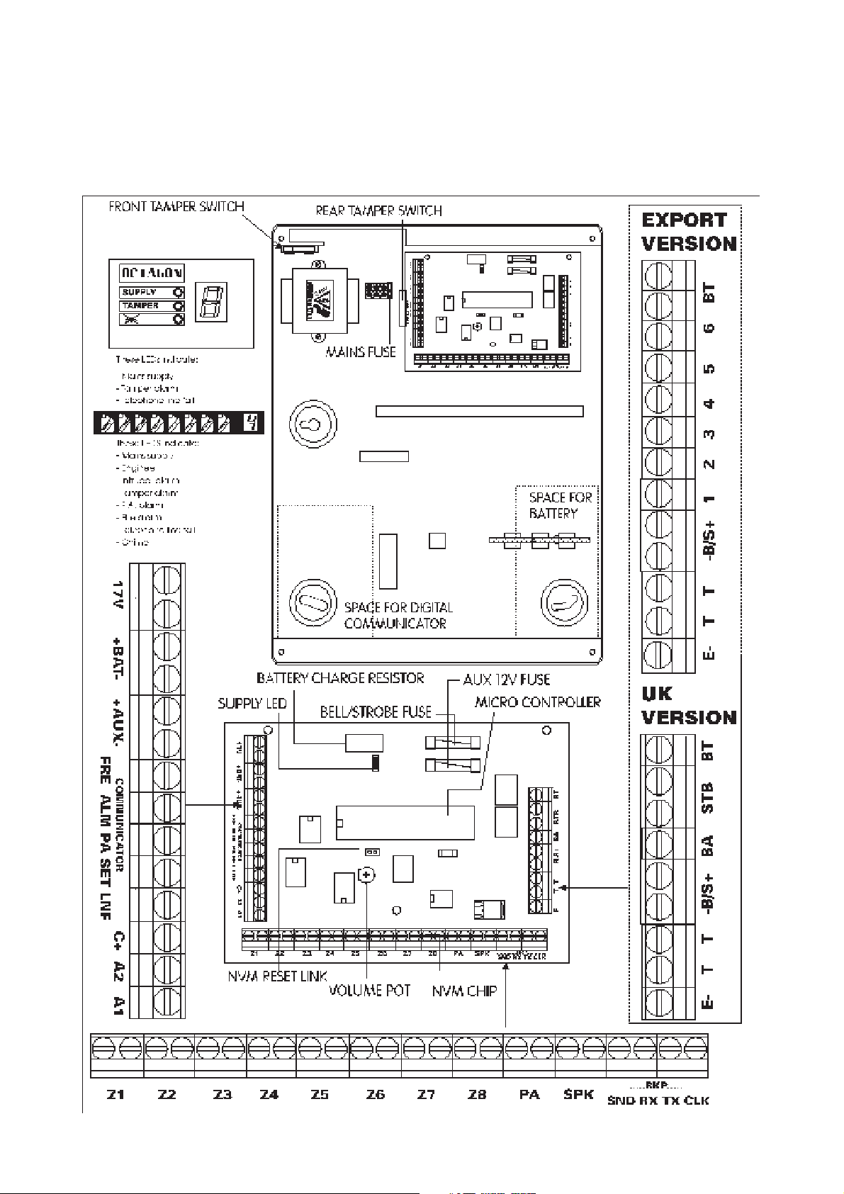
8.1 Plan View With Cover Removed.
8
Page 9

8.2 Mounting.
1 Remove front cover.
2 Hang the control panel base onto the wall with the central mounting hole using one of the screws and plugs
provided.
3 If possible use a spirit level or some other means to position the control panel squarely then drill the remaining
holes into the wall to locate the screws and plugs.
8.3 Mains connection.
1 The mains supply connector should be carefully wired to an ac mains supply using a suitably rated 3 core cable
with a current carrying capacity of not less than 5 Amps. It should be connected to a fused spur with a fuse rating
of not more than 2 Amps.
2 The mains connections at the power supply terminal block are coded as follows:
L : LIVE
: EARTH
N : NEUTRAL
8.4 Battery capacity.
It is recommended that the rechargeable battery used with the Octagon II control panel should be capable of powering
the alarm system for a minimum of 8 hours, and that this time period include 20 minutes of bell/strobe operation.
The minimum battery capacity should be calculated from the current consumption of the individual system components.
A typical example is shown below:
Non alarm current for control panel ( 7 hrs 40 min) : 174mA (0.174 A)
Steady state current for detectors : 120mA (0.12 A)
(e.g. 8 x 15mA for 8 hours -Pyronix PIRS)
Typical stand-by current for external sounder : 50mA (0.05 A)
(e.g. Self Actuating Bell for 8 hours)
Typical on state current for external : 350mA (0.35 A)
sounder (20 mins)
Alarm state current for control panel (20 mins) : 140mA (0.140 A)
Typical current for external strobe (8 hours) : 150mA (0.150 A)
Total battery capacity = (Panel stand-by current x 7hrs 40min)
For example it is recommended that you use a battery of not less than 4.1 Ah, the nearest size above this being 6Ah.
8.4.1 Battery Charging.
This Octagon II has a fast battery charge circuit capable of recharging a 6Ah battery in 12 hours
NB: 1) Do not allow any cables or wiring to touch the battery charge resistor ( See diagram on Page 9 )
High resistor temperature during battery charging will damage insulation to wires touching this resistor, resulting in
incorrect operation of the control panel.
NB: 2) Do not use a battery of less than 2.8Ah capacity
8.5 Low Voltage Connections.
8.5.1 Extension Loudspeakers.
Extension loudspeaker (SPK).
External Sounder/Bell.
RDOC298D/E Issue 1
+ (Detectors, SAB and strobe current x 8hrs)
+ (Panel in alarm with external sounder x 20mins)
i.e. 0.174 X 7.67HRS
+ (0.12 + 0.05 + 0.15) X 8HRS
+ (0.40 + 0.35) X 0.33HRS
~ 4.1 Amp Hours
S+ : 12 volts dc supply
-B : 0 volts
1 BNO : Bell Normally Open
2 BNC : Bell Normally Closed
3 BC : Bell Common
4 SNO : Strobe Normally Open
5 SNC : Strobe Normally Closed
6 SC : Strobe Common
9
Page 10
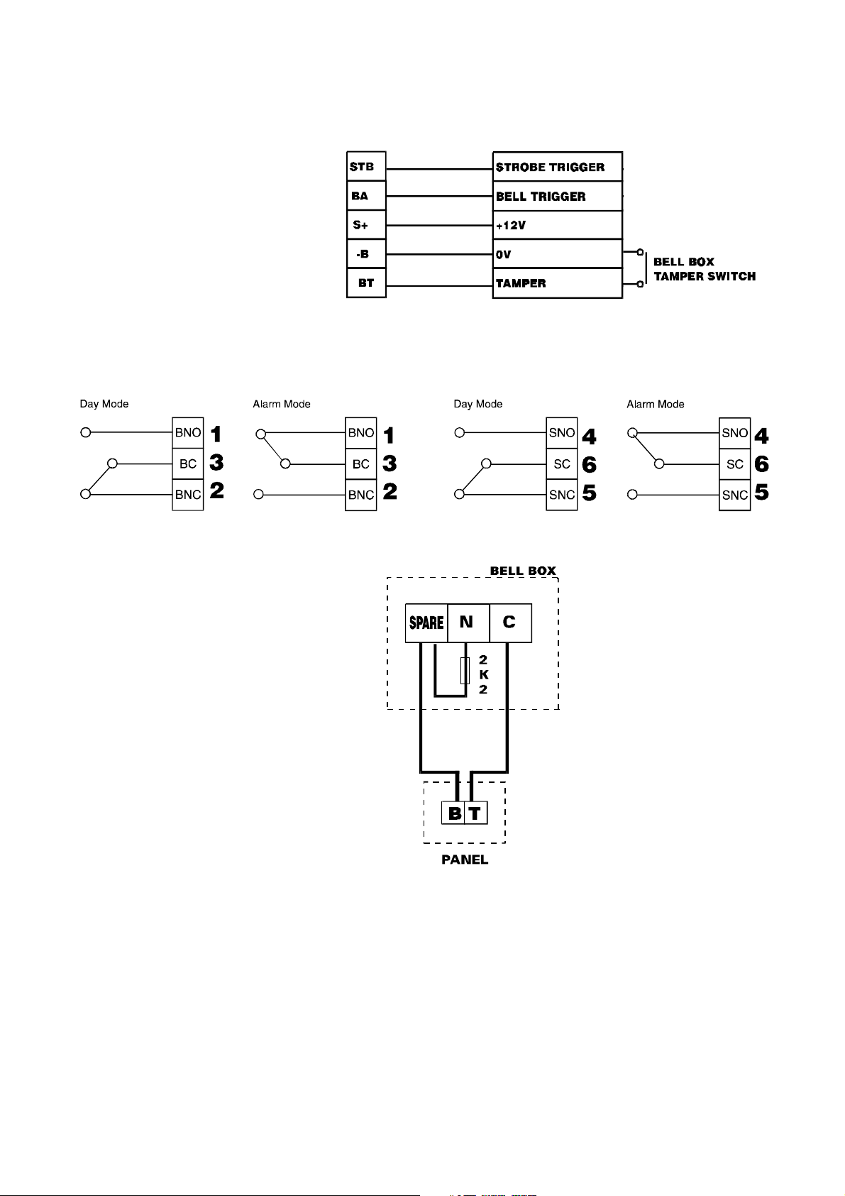
8.5.2 Wiring The Bell And Strobe (UK Version).
PANEL BELLBOX
STB : Negative Trigger
BA : Negative Trigger
S+ : 12V dc Supply
-B : 0v dc Supply
BT : Bell Tamper (negative return)
8.5.3 Wiring the External Siren (Export Version). Wiring the Strobe.
10
Page 11

8.5.4 Remote Keypads.
Remote Keypads Continue...
RDOC298D/F Issue 1
11
Page 12

8.5.5 End of line resistors.
The Octagon II panel uses resistors on all of its end of Line zones. Two resistor values are used, these are 2K2 and a 4K7.
To identify the two resistors, coloured bands on the body are used. These are has follows:
2K2 4K7
The fourth coloured band should be ignored.
Any unused zones should NOT be left open circuit. These should have a 2K2 resistor inserted:
8.5.6 Wiring to PIRs and other Sensors.
Wiring to one sensor Wiring to two or more sensors
TT Normally closed tamper terminals.
NC Normally closed alarm terminals.
8.5.7 Wiring to Door Contact.
Wiring to one door contact Wiring to two door or more contacts
12
*N.B. Up to ten sensors or door contacts are permitted on each zone*.
Page 13

8.5.8 Wiring To A Personal Attack Button.
Any number of P.A. buttons may be used.
"NB. If the P.A. terminal is not used it must be linked out with a 2K2 resistor."
8.5.9 Wiring To Rkp Remote Zone.
The RKP remote Zone is End Of Line so must be wired as in diagrams 8.5.6 Sensors / 8.5.7 Door Contacts/ 8.5.8 P.A.
buttons. If the RKP remote zone is not used it must be linked out with 2K2 resistor.
The default for the zone is Entry / Exit.
8.5.10 Wiring the Keyswitch inputs A1 / A2.
The Octagon II PCB has two keyswitch inputs labelled A1 and A2.
The keyswitch inputs will operate the panel if they are connected to the auxiliary negative terminal.
8.5.11 Wiring the communicator outputs / inputs.
The communicator outputs can be programmed to set positive (12v) or set negative (0v). The outputs provide sufficient
current to activate communicator inputs without the use of relays etc. The communicator line fail input (LNF) operates when
connected to ground (0v).
8.5.12 Wiring the Latch output (C+).
The latch (C+) output is used to disable a detectors LED. When the panel is armed the latch sets positive (12v) disabling
the LED.
When the panel is unset the latch line toggles resetting the detectors LED. All detectors must be wired in series to the latch
output.
8.5.13 Wiring the LED enable E- / shock reset output.
LED Enable E-.
If a detectors E- terminal has been connected to the E- terminal in the panel, the detectors LED will operate during walk
test even if the detectors LED disable link has been removed. All detectors E- terminals must be wired in series back to
the panel.
Shock sensor reset.
The power supply negative terminal on the shock sensor is connected to the shock sensor reset terminal.
After an activation the power supply is interrupted momentarily to reset the sensors.
8.6 Powering up your panel
1 Switch on the mains supply then insert and connect the back-up battery.
2 A tone will be emitted and the tamper LED will flash on the RKP. Replace the front cover of the panel and enter
the Master User code twice (
)
3 The panel is now programmed to its factory settings.
RDOC298D/G Issue 1
13
Page 14

9 PROGRAMMING
9.1 Factory defaults.
User code 1 : 1234 (programmable 0000 to 9999).
User code 2 If enabled : 5678 (programmable 0000 to 9999) .
Cleaner Code If enabled : 7890 (programmable 0000 to 9999).
Engineer code : 9999 (programmable 0000 to 9999).
Bell timer : 20 minutes (programmable 0 to 20 mins).
Entry time : 30 seconds (programmable 0 to 99 secs).
Exit time : 30 seconds (programmable 0 to 99 secs).
The following key shows possible zone configurations-
E = Entry/exit zone S = Soak zone
i = Immediate zone c = Cleaner zone
A = Access zone n = Non-omit zone
O = Omitted zone F = Fire zone
H = 24 Hour zone
The zone types are factory set as follows: Zone number
1 2 3 4 5 6 7 8
Full set E A i i i i i i
Part set A E A i i i i i i
Part set B E A i i i i i i
Part set C E A i i i i i i
9.2 User and Engineer Codes.
9.2.1 Entering and exiting the Engineer mode.
With the control panel in day mode enter the Engineer code
will be displayed on the remote keypad(s) when the Octagon II is in Engineer Mode. Any covers may now be
A
removed
without creating a tamper alarm and access is now given to the programming functions of the control panel.
To exit Engineer mode enter
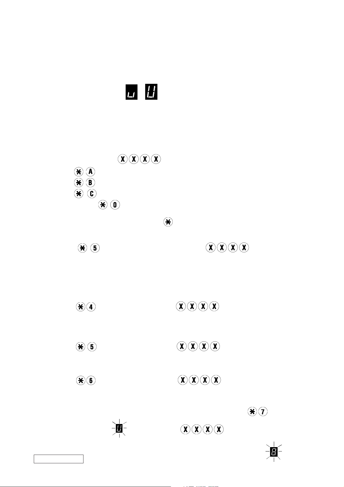
9.2.2 Enabling the Limited User (user 2) code.
To enable the Limited user code first enter Engineer mode as above then
enter
To disable the Limited user code
enter
9.2.3 Enabling the Cleaner code.
In Engineer mode enter
followed by to enable.
followed by . The default Limited user code is .
. This will return the control panel to day mode.
followed by to enable, or followed by to disable the cleaner code.
.
The default cleaner code is .
9.2.4 Changing the Engineer code.
In Engineer mode enter followed by your new Engineer code twice
Your new code may be any 4 digit number from to .
14
Page 15

9.3 Timers.
9.3.1 Exit Time.
Whilst in Engineer mode enter
followed by the desired exit time in seconds
The exit time may be any 2 digit number from to .
9.3.2 Entry Time.
Whilst in Engineer mode enter
The entry time may be any 2 digit number from
followed by the desired entry time in seconds .
to .
9.3.3 Bell Delay.
In Engineer mode enter followed by the desired bell delay in minutes .
The bell delay will prevent extension speakers and external sirens from operating for the length of time entered.
The bell delay may be programmed as any 2 digit number from
to .
9.3.4 Bell Time (External Sirens).
In Engineer mode enter
followed by the required bell cut off time in minutes .
The bell time cut of time may be any 2 digit number from to .
9.3.5 Communicator Delay.
A communication delay may be programmed for the Alarm, P.A. and Fire outputs. These outputs will not operate after an
activation, until the communicator delay has expired.
Whilst in Engineer mode enter
followed by a 2 digit time in seconds .
The communicator delay may be programmed as any 2 digit number from to .
9.3.6 Number of Rearms.
In Engineer mode enter
followed by the number of rearms .
This is the number of times the control panel will rearm itself after activating the external sirens for the bell time programmed.
The number of rearms may be any number from to .
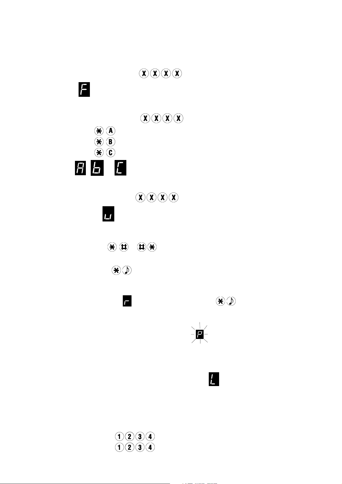
9.3.7 Part Set Types.
The three part sets A, B and C may be programmed as timed set, silent timed set or instant set. All three part sets are factory
programmed as timed set.
To alter any of these first enter Engineer mode then press
followed by:
Key part set A, or
part set B, or
part set C
The letter pressed will be displayed on the keypad.
Then key either
timed set, or
silent timed set, or
instant set
The relevant symbol will be displayed on the remote keypad for a few seconds.
To alter the remaining part sets repeat the above sequence.
RDOC298D/H Issue 1 15
Page 16

9.4 Programming Set Modes.
9.4.1 End of line Zones.
The zone defaults given in the table on page 15 can be reprogrammed to an alternative zone type. The procedure to change
these is as follows.
In Engineer Mode choose the new zone type and enter the code: see chart below
Enter the numbers of the zones you wish to change. Enter to confirm. This will return the control panel to engineer
mode. Repeat the above sequence to change any other zones.
Example 1.
To reprogram zone 5 in part set B from immediate to access: Enter Engineer Mode (
Press
. (zone code for access)
)
Press . (to select part set B)
Press
. (to program zone 5)
Press . (to enter data)
Example 2.
To reprogram zones 6,7 and 8 in part set C to omit: Enter Engineer Mode (
Press
. (to select omit zones)
)
Press . (to select part set C)
Press and (to program the three zones)
Press
.(to enter data
16
Page 17

Example 3.
To reprogram zone 4 as a Fire zone: Enter Engineer Mode (
)
Press . (to select Fire zone)
Press . (to program zone 4)
Press
. ( to enter data)
NOTE: Any zones programmed as cleaner, fire or 24 hour will keep these zone types in full set and all three part sets.
After following all 3 examples the zones have been reprogrammed as follows:
Zone number
1 2 3 4 5 6 7 8
Full set E A i F i i i i
Part set A E A i F i i i i
Part set B E A i F A i i i
Part set C E A i F i O O O
9.4.2 Remote Zones.
Each Octagon II RKP incorporates a remote zone. This zone requires end of line resistors and may be programmed as
Entry / Exit, P.A. or " push to set". In Engineer mode:
Key
. The symbol will be displayed on the RKP. Enter the zone type required from the chart below
:
N.B. The function selected applies to all RKP's wired to the Octagon II control panel. If more than one RKP is used then
all remote zones will be programmed together by the above sequence.
9.5 Miscellaneous Programming Options.
9.5.1 Tamper Alarm.
Activation of a tamper circuit whilst the control panel is in day mode will normally only activate the extension speakers.
It is possible to program the Octagon II to also activate the external sirens when a tamper alarm is generated in day mode.
This is done as follows:
In Engineer mode enter
followed by to enable external sirens as above, or to disable external sirens
as above.
9.5.2 Tamper Activation.
As for "Tamper alarm" given above the digital communicator alarm output will not normally be triggered following activation
of a tamper circuit in day mode. It is possible to program the Octagon II to activate the communicator alarm output as follows:
In Engineer mode enter
followed by to enable the communicator as above, or to disable the
communicator as above.
9.5.3 Personal Attack (P.A.) Alarm.
Activation of the P.A. zone whether in day mode or any of the four set modes will activate the communicator output and
any extension speakers, together with the external siren. The Octagon II control panel can be programmed to operate the
communicator output ONLY, giving a "silent P.A.". Programming is as follows.
In Engineer mode enter
Silent P.A. should only be used if a communicator is fitted.
RDOC298D/I Issue 1
followed by to select "silent P.A.", or to select "Audible P.A."
17
Page 18

9.5.4 Continued Speaker Activation
The extension speaker and external siren outputs will normally be silenced at the end of the preprogrammed "bell time".
However, the extension speaker can be programmed to continue until the control panel is disarmed. For continued speaker
operation enter engineer mode, followed by
then for continued speaker operation, or for timed speaker
operation.
9.5.5 User / Engineer Reset.
The Octagon II control panel is factory set to "user reset". This means that the users can rearm the system after an alarm
has been generated. It is however possible to prevent the user from operating the system after an alarm activation. In this
instance the Engineer code must be entered before the control panel can be set again.
This is known as "Engineer reset".
To program Engineer reset enter Engineer mode then press
followed by to select Engineer reset, or
to select user reset.
9.5.6 Timed Exit / Final set.
The control panel is factory programmed to suspend the exit timer if any of the zones are open. The panel will set when
the exit time has expired and all zones are closed. In some instances the exit timer may continue for some time after the
exit route has been cleared, requiring the user to wait for the entry / exit tone to stop. To eliminate the need for the user
to wait for the exit time to end the control panel can be programmed to set immediately after an Entry / Exit zone has closed.
This is known as "final set".
To do this enter Engineer mode, press
followed by to select final set , or to select timed exit.
Note: If final set is selected and any other zone remains open when the entry / exit zone closes the control panel will
not set. It will wait until all zones are closed. If a zone opens immediately after the entry / exit zone closes a warning tone
will be heard at the keypad and this tone will end when the zone is closed. The system will then set.
9.5.7 Communicator Set / Unset Polarity.
The Communicator set / unset output can be programmed to operate as switched positive (0 Volts to 12 Volts) or switched
negative (12 Volts to 0 Volts). The factory programmed setting is set positive / unset negative.
In Engineer mode enter
followed by to select set negative, or for set positive.
9.5.8 Communicators Output Polarity Settings, (P.A., Alarm and Fire).
The communicator outputs can be programmed to operate as set positive (0Volts to 12Volts) or set negative (12Volts
to 0Volts) . The factory programmed setting is switched negative.
In Engineer mode enter
followed by to select set negative, or to select set positive.
9.5.9 Setting the Panel when Mains fails.
Under normal operation the panel can be set if the mains supply is disconnected (providing the system is battery backed).
A flashing and tamper LED will be displayed if this occurs.
In Engineer mode enter
followed by not to allow the panel to be set if mains fails, or to allow mains
fail setting.
9.5.10 Setting The Panel With No Battery Or Low Battery .
Under normal operation the panel can be set if there is no battery or the battery voltage is low.
A flashing
In Engineer mode enter
and tamper LED will be displayed if the battery voltage is low or is not connected.
followed by not to allow the panel to be set with no battery / battery low, or
to allow setting.
9.5.11 Keyswitch Options.
Both keyswitch inputs can be programmed to arm the system in full set or part set C. Both inputs may be configured for
use with either momentary action (pulsed) or latching (fixed contact) switches.
These switches require the inputs A1 and A2 to be connected to 0 Volts. Input A1 is programmed as follows:
In Engineer mode press
followed by:
for full arm / disarm with a momentary switch.
for part set C arm / disarm with a momentary switch.
18
for full arm /disarm with a latching switch.
Page 19

for part set C arm / disarm with a latching switch.
for push to set.
Input A2 is programmed as above with from engineer mode.
Input A1 is factory set to option 1.
Input A2 is factory set to option 2.
9.5.12 Remote LED Enable / Shock Reset Modes.
Remote LED enable (E-) mode allows the operation of detector LED's during Walk Test if the detectors have had their
LED disable links removed. Shock / Smoke sensor reset mode momentarily switches off the power to this terminal to reset
the sensors after an alarm activation.
In Engineer mode enter
followed by for shock / smoke sensor reset, or for remote LED enable.
9.6 Setting volume control.
This control is set by adjusting the volume pot as shown in fig 8.1. This control will affect the volume produced by any
extension speakers. The volume control will be overridden to provide full volume during an alarm activation.
9.7 Resetting the non volatile memory (NVM) .
9.7.1 Factory settings.
The following operation will reset all programming described in this section back to factory defaults. To reset the NVM first
disconnect the mains supply to the control panel. Then disconnect the backup battery negative terminal and short out the
two pins on the NVM reset link as shown in fig 8.1.
A shorting link is provided for this purpose. Next reconnect the mains supply. A short tone will be heard and the RKP
will display a
. Normal operation will continue when the jumper is removed.
Finally, reconnect the battery negative terminal.
9.8 Programme Mode Test Facilities.
9.8.1 Walk Test.
A walk test of the Octagon II control panel will give an audible and visual indication of zone, tamper and P.A. activations.
If any zones are active a high tone will be generated from the keypad. If all zones are inactive then a low tone will be heard.
All zone activations during a walk test will be entered into the event log.
To perform a walk test first enter Engineer mode then press
. To end walk test press to return to Engineer mode.
9.8.2 Bell Test.
The bell output can be activated as follows:
Enter engineer mode then press . To end bell test press to return to Engineer mode.
9.8.3 Strobe Test.
The strobe output can be activated as follows:
Enter Engineer mode then press
.To end strobe test press to return to Engineer mode.
9.8.4 Latch Output Test.
The latch output can be activated as follows:
Enter Engineer mode then press
. The latch output will change from 0Volts to 12Volts. To end latch test press
to return to Engineer mode. The latch output will return to 0Volts.
9.8.5 Communicator Test.
All three communicator outputs can be tested individually. This is performed as follows:
In Engineer mode enter
Each time numbers 1 to 4 are pressed the relevant output will change state from 0Volts to 12Volts or 12 Volts to 0Volts.
All four outputs can therefore be tested together. To return to engineer mode press
RDOC298D/J Issue 1
followed by to activate alarm output
to activate P.A. output
to activate set / unset output.
to activate Fire output
.
19
Page 20
9.8.6 Speaker Test.
This will activate all extension speakers and RKP speakers. In Engineer mode press
, to end speaker test output
enter .
9.8.7 Event Log.
The Octagon II control panel has a 100 event memory which will store a variety of set/unset and alarm events.
To view the event log enter engineer mode and then press . The most recent event will be displayed.
To scroll forward press
To scroll backwards press
To exit log viewing press
To clear the event log press
.
.
.
.
Note: If the event log contains less than 100 events the control panel will return to Engineer mode when all recorded
events have been displayed.
1. Indicates that the next event caused the alarm activation when the panel was in day mode.
RKP II LED display layout RKP display layout
2. Indicates that the next event caused the alarm activation when the panel was full set.
3. Indicates that the next event caused the alarm activation when the panel was part set A.
4. Indicates that the next event caused the alarm activation when the panel was part set B.
5. Indicates that the next event caused the alarm activation when the panel was part set C.
6. Indicates the panel was set.
7. Indicates a Personal Attack activation or a flashing ' P ' indicates an Engineer walk test activation.
20
Page 21
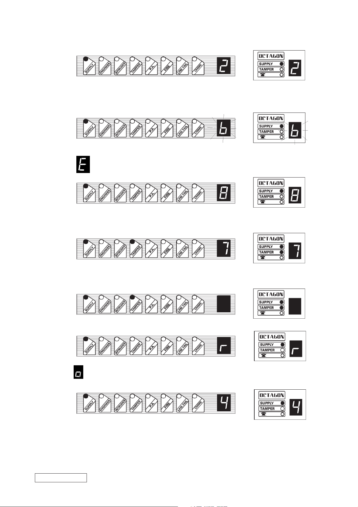
8. A number indicates a zone activation.
e.g. zone 2
9. A flashing number indicates a soak zone activation.
e.g. zone 6
10.
Followed by number shows an Engineer walk test activation.
e.g. zone 8
11. A number and the tamper LED indicates a tamper zone activation.
e.g. zone 7
12. The tamper LED indicates a bell or case tamper.
13. Indicates an entry/exit activation of the remote keypad zones.
14. followed by a number shows a user omitted zone.
(e.g. zone 4 was omitted here during the setting sequence).
RDOC298D/K Issue 1
21
Page 22
1 0 USING THE OCTAGON II AFTER PROGRAMMING
10.1. Cleaner Functions.
10.1.1 Full Setting the Panel.
To full set the system enter the cleaner code .
The full set symbol will be displayed until the panel sets.
10.1.2 Part Setting the Panel.
To part set the system enter the cleaner code
for part set A
for part set B
for part set C
A part set symbol
10.1.3 Unsetting The Panel.
To unset the system enter the cleaner code
The keypad display will show
are activated at this time will create a full alarm.
10.1.4 Activating Personal Attack (P.A.) Alarm.
To activate the P.A. alarm enter
10.1.5 Turning Chime ON and OFF.
With the panel in day mode enter
As this feature is turned on a two tone chime will be given by the remote keypads and any extension speakers (if fitted).
With chime enabled any zones programmed to chime by the Master user will cause the same two tone chime to be given
by the remote keypads and speakers. The chime zone number will also be displayed on the RKP. A chime caused by a
, OR will be displayed until the panel sets.
which indicates that the system is not completely unset. Any cleaner zones which
or
.
followed by
.
RKP remote zone will be displayed as
10.1.6 Cancelling a Power Failure.
In day mode if the mains supply is interrupted the tamper LED and
A tamper tone will be generated by the remote keypad. To cancel this tamper alarm enter any user code.
10.1.7 Communicator Line Failure.
If the communicator is used which incorporates a line fail output this output may be connected to the line fail input on the
control panel. If this input is activated (switched to 0Volts from 12Volts) then
will illuminate and a tone generated.
Any subsequent alarm activation will cause the bell delay to be overridden, causing the external sirens to operate
immediately.
10.1.8 Duress Code.
If the last two digits of a user code are reversed when arming or disarming the panel, the digital communicator personal
attack output is activated. The correct code must be entered to reset the P.A. communicator output.
22
e.g. Code
Duress code
To turn off the chime facility enter .
will flash.
will flash on the RKP, the line fail LED
Page 23
10.2 Limited User Functions (user 2).
10.2.1 Cleaner Functions.
The limited user has access to all the cleaner functions as well as those listed below. The Octagon II control panel has
to be in day mode for these additional features to be accessed.
10.2.2 Deactivating Cleaner Zones.
If the control panel has been reset using the cleaner code the cleaner zones will still be active. If the limited user code
is entered the display will change from
to and all cleaner zones will be deactivated.
The Cleaner cannot reset the panel if there has been an alarm activation.
10.2.3 Omitting Zones.
If one or more "immediate" zones are triggered whilst in exit mode a warning tone will be produced and the zone number
will be displayed. If the zone clears the warning tone will change to an exit tone and the full set / part set indicator will be
displayed.
If the zone does not clear and the warning tone continues the faulty zone can be omitted. If this is not done the system
will not set.
To omit a zone enter any user code
followed by
for part set A
.
for part set B
for part set C as required.
During the exit period enter . The display will clear and a rapid tone will be produced. Now enter the numbers
of any zones which need to be omitted. Zone 9 will omit the remote RKP zones. The control panel will acknowledge these
by displaying the zone number(s) selected. Now enter to allow the exit period to continue.
10.2.4 Changing Limited User Code.
In day mode enter
followed by the existing Limited user code . The keypad will bleep to
acknowledge that this code is correct. Then enter the new Limited user code twice. After each input the keypad will give
an acknowledgement bleep. If a code is not entered correctly the keypad will give an error tone and return to day mode.
10.3 Master User Functions (user 1).
The master user has access to all the Limited user and cleaner functions as well as those listed below.
10.3.1 Changing Cleaner Code
In day mode enter
followed by the Master user code . The keypad will bleep to acknowledge
that the code is correct. Then enter the new Cleaner code twice. After each input the keypad will bleep. If the code is not
entered correctly the keypad will emit an error tone and return to day mode.
10.3.2 Changing Limited User Code
In day mode enter
followed by the Master user code . Then enter the new Limited user code
twice.
10.3.3 Changing Master User code.
In day mode enter followed by the Master user code . Then enter the new Master user code
twice.
10.4 System Test Mode.
This function performs a number of system tests which are listed below. In day mode enter
The "unset" display will now flash Now enter user code .
RDOC298D/L Issue 1
The three display LEDs on the keypad will all turn on and the number display will show a flashing
23
Page 24

Now press The strobe output will be activated.
press
The strobe output will turn off and the bell output will switch on.
press The bell output will turn off and any extension speakers fitted will sound.
press The extension speakers will turn off and the panel will return to day mode.
10.4.1 Walk Test.
To verify the operation of all detectors in the alarm system a user walk test feature has been included.
To perform a walk test enter
The unset display will now flash Now enter the Master user code .
If any zones are active a high tone will be generated from the keypad and the zone numbers will be displayed on the keypad.
If all zones are inactive then a low tone will be heard.
Enter
to end walk test.
Note: Unlike the Engineer walk test the Master user walk test will not enter zone activations into the event log.
10.4.2 Chime Programming.
In order to increase system flexibility the chime programming may be performed by the Master User. Four chime options
are available on the Octagon II control panel and these are: Day mode.
Part set A
Part set B
Part set C
In day mode, any of the eight standard zones may be programmed to chime. In addition to this when the system is part
set any omitted zones can also be programmed to chime. This allows the chime to operate at any time except when the
control panel is full set. Chime is programmed as follows:
In day mode enter
.
The keypad display will change to (flashing) to indicate that chime programming has been selected.
Now enter the Master User code
, the keypad will bleep to acknowledge that the code is correct.
Next enter for Day mode
for Part set A
for Part set B
for Part set C
The keypad will bleep to acknowledge a key press. Now enter the numbers of the zones you wish to chime.
Pressing will clear all chime zones and should be used if reprogramming is necessary.
When all zone numbers have been entered press
to return to day mode. Programming of another mode to chime will
require the above sequence to be repeated.
10.4.3 Event Log.
The Master User may view the event log. To view the event log enter
.
The unset display will now flash Now enter the Master User code , the last zone activation will
be displayed on the RKP.
Key
to scroll backwards.
24
to scroll forwards.
to clear log (if enabled by engineer).
to exit to day mode.
Note: Keypad, Personal Attack will not operate while event log view is selected.
Page 25

10.4.4 Engineer Code Arming.
The engineer may set and unset the panel if it has previously been unset by the Master User Code.
To arm panel enter . The unset display will now flash Now enter the Engineer code
The panel will now arm
Enter
or
or To part set the panel.
To return to day mode enter Engineer code
.
1 1 LED FUNCTIONS
Panel PCB
Supply LED on : Indicates a mains supply
Remote Keypad
Supply LED on : Indicates a mains and/or battery supply
Tamper LED : Indicates a tamper fault
Tamper LED flashing : Indicates a mains failure
when arming the panel
Line Fail LED on : Indicates a communicator line fault
RDOC298D/M Issue 1
25
Page 26

1 2 TECHNICAL SPECIFICATION
12.1 Power supply.
Power input:
230V version : 230V ac +/- 10% 50Hz/60Hz.
220V version : 220V ac +/- 10% 50Hz/60Hz.
Power input fuse:
230, 220V versions : 250mA quick blow.
Low voltage output : 13.2 Vdc fused, 1.25 Amp maximum
Including Central Panel. 1Amp
maximum available for external devices.
Low voltage output fuses : 1 Amp quick blow.
Battery charge voltage : 13.7 Vdc.
Rechargeable battery capacity : 12V sealed lead acid, 1.2 to 6 AH.
12.2 Control PCB.
Current consumption
(day mode) : 206mA.
(set mode) : 179mA.
(alarm) : 190mA.
Auxiliary DC output supply : Regulated 13.2Vdc for use with PIR,
microwave and shock sensors.
Extension Speaker load : 8 to 32 Ohms.
Bell : 500mA.
Strobe : 500mA.
Alarm bell timer : 0 to 20 minutes (software
programmable).
Zone type : Normally closed loops which activate
when opened or short circuit.
Zone loop current : 0.76 to 1.03mA.
Zone activation resistance : 6.9K Ohms (minimum).
Zone loop activation timer : 0.35 seconds.
Exit timer : 0 to 99 seconds.
Entry timer : 0 to 99 seconds.
12.3 Mechanical.
Dimensions : 240 x 305 x 70mm.
Case material : 1.2mm thick Mild steel with screw fixing
front cover.
Colour : White.
Weight excluding battery : 2.9Kg.
12.4 Environmental.
Operating temperature : 0 to +40
Storage temperature : -20 to +60
0
C (+32 to +1040 F).
0
C (-4 to +1720 F).
12.5 Cleaning.
DO NOT use strong detergents to clean this control panel. To remove any dirt or grime, wipe with a clean damp cloth ONLY
26
Page 27

1 3 TROUBLESHOOTING
The following guide shows the most common displays given by the Octagon II remote keypad. If an incorrect function
code is entered and it is not known what input the control panel is expecting next, please wait.
The control panel will only wait for approximately 1 minute before reverting back to either day mode or Engineer mode.
If this does not work press
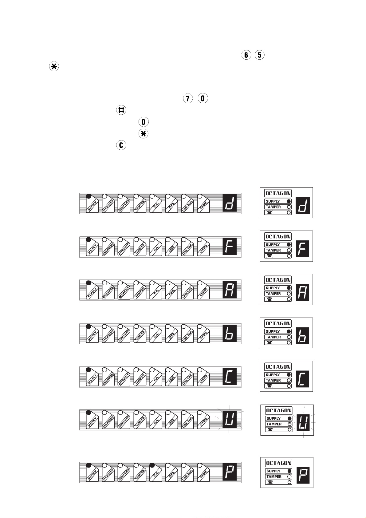
1 Panel unset (Day Mode).
RKP II LED display layout RKP LED display
layout
During Exit Mode the following four symbols are displayed flashing.
2 Full set indication
3 Part set A
4 Part set B
, then wait again.
5 Part set C
6 Panel set
7 Programming Mode.
8 NVM reset.
9 Communicator Line Failure ( Day Mode).
10 Battery Lowl / No Battery ( Day Mode).
A
RDOC298D/N Issue 1
and the tamper LED will flash for a second when arming the system.
27
Page 28

11 Remote Zone open circuit.
12. When the panel has been unset with the Cleaner Code a small 'U' is displayed.
13 Mains Failure in Day Mode - providing system is battery backed a tone will be emitted.
A
and the tamper LED will flash for a second when arming the system.
14 Chime selected.
15. No Battery / Low Battery / Power Fail.
When trying to arm the panel the tamper LED flashes and the tamper tone is emitted there is
For the following conditions the violation indicated will cause a continuous tone to be heard. Enter a user code once
to display the system violation. Enter the user code a second time to return to Day Mode (Tamper circuits must be closed
before system can return to Day Mode).
16 Case tamper / Bell tamper.
17 Zone tamper. LED display shows tamper zone. (e.g. zone 4).
18 P.A. Alarm.
19 Alarm. LED display shows zone violated (e.g. zone 4).
28
Page 29

20 Intruder alarm. The LED display shows the number of the zone activated.
21 Fire alarm. The LED display shows the number of the zone activated.
22 Engineer code is required to reset the panel. The LED shows the number of the zone activated.
14. SYSTEM STATUS
RDOC298D/O Issue 1
29
Page 30

15. LIMITED USER QUICK REFERENCE GUIDE
30
Page 31

16. ENGINEER QUICK REFERENCE GUIDE
17. ZONE PROGRAMMING LABEL
18 . OCTAGON II SERVICE HISTORY
RDOC298D/P Issue 1
31
Page 32

32
Page 33

RDOC298D/Q Issue 1
33
 Loading...