

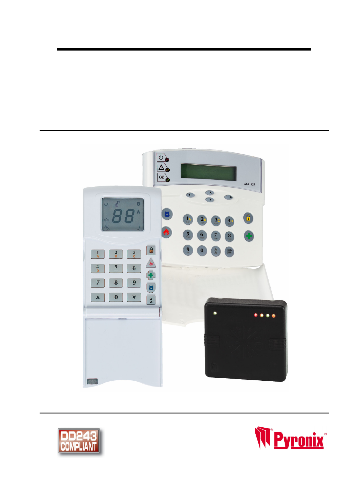
Matrix Installation Guide
This Guide Supports the Following Panels:
MATRIX 832
MATRIX 832+
MATRIX 424
RINS428-5
Tel: +44(0) 1709 700100

Pyronix Association of Security Specialists
Installer Support
The Pyronix Association of Security specialists has been developed with the focus on what you the installer
would like to see from one of the leading manufactures of security equipment.
The philosophy behind the association is that you will receive tangible benefits, which are applicable to both
the work and home environment.
The Association Awards Catalogue
By collecting the tokens which are printed on the packaging you can redeem against gift vouchers for Argos,
Marks & Spencer and Whitbread Leisure.
Product Consultation
Product training and consultation evenings are provided up and down the country.
To join PASS please contact our marketing department:
marketing@pyronix.com
Tel: +44 (0)1709 700100
technical.support@pyronix.com
As a new member of PASS you will be issued with a free technical support telephone number.

Matrix 832 / 832+ / 424
Contents
SECTION 1: TECHNICAL SPECIFICATIONS & SYSTEM OVERVIEW ..............................1
1.1 Technical Specifications........................................................................................................1
1.1.1 Main Control Panel............................................................................................................................1
1.1.2 Additional Expanders ........................................................................................................................3
1.2 Battery Capacity Calculations...............................................................................................4
1.2.1 UK Requirements..............................................................................................................................4
1.2.2 Norwegian & Danish Requirements..................................................................................................4
1.2.3 Swedish Requirements .....................................................................................................................4
1.3 System Overview....................................................................................................................5
SECTION 2: SAFETY & APPROVALS ................................................................................9
SECTION 3: MOUNTING PROCEDURE............................................................................14
3.1 Mounting Procedure for Matrix – Plastic & Metal Case .................................................... 14
3.2 Panel Layout – Plastic Case ................................................................................................14
3.3 Panel Layout – Metal Case ..................................................................................................15
3.4 Battery Installation Procedure ............................................................................................15
SECTION 4: CABLING RULES FOR THE MATRIX BUS..................................................16
4.1 System Examples .................................................................................................................17
SECTION 5: OPERATING MODES....................................................................................19
5.1 Disarmed Mode.....................................................................................................................19
5.2 Armed Mode..........................................................................................................................19
5.3 Arm Mode .............................................................................................................................. 19
5.4 Entry / Exit Mode ..................................................................................................................19
5.5 Alarm Mode ........................................................................................................................... 19
5.6 Anti-Code Reset....................................................................................................................19
5.7 First to Alarm Mode..............................................................................................................20
5.8 Engineer Mode......................................................................................................................20
5.9 User Mode .............................................................................................................................20
SECTION 6: KEYPAD/READER SYMBOLS & INDICATIONS..........................................21
6.1 The ICON Keypad .................................................................................................................21
6.2 The LCD Keypad...................................................................................................................22
6.3 The Proximity Reader...........................................................................................................22
SECTION 7: PROGRAMMING THE SYSTEM ...................................................................23
7.1 Addressing the LCD & ICON Keypads ...............................................................................23
7.2 Addressing the Proximity Reader....................................................................................... 24
7.2.1 Connection of MX PROX to a PC ...................................................................................................24
7.3 Finding Bus Devices ............................................................................................................25
7.4 Factory Default Settings of Matrix System ........................................................................25
7.4.1 Engineer Code ................................................................................................................................25
7.4.2 Global System Options ...................................................................................................................25
7.4.3 Zone Types, Zone Attributes & Zone Settings................................................................................26
7.4.4 User Codes, User Code Attributes & Proximity Card Allocation.....................................................27
7.4.5 Keypads & Proximity Readers Partition Allocation .........................................................................27
7.4.6 System & Tamper Faults Partition Allocation..................................................................................27
7.4.7 Partition Options..............................................................................................................................27
7.4.8 Arm Options ....................................................................................................................................27
7.4.9 System Timers ................................................................................................................................28
7.4.10 Programmable Outputs.................................................................................................................28
7.4.11 Digital Communicator....................................................................................................................29
7.4.12 Communication Formats...............................................................................................................29
7.4.13 Events Reporting...........................................................................................................................29
7.4.14 DD243 Option Defaults .................................................................................................................30
7.4.15 Confirmation Timer Defaults .........................................................................................................30
7.4.16 Zone Mapping Defaults.................................................................................................................31
RINS428-5 Page i

Matrix 832 / 832+ / 424
7.5 Entering / Exiting Engineer Mode .......................................................................................32
7.5.1 Entering Engineer Mode................................................................................................................. 32
7.5.2 Exiting Engineer Mode ................................................................................................................... 32
7.5.3 Changing Engineer Code............................................................................................................... 32
7.6 Global System Options ........................................................................................................33
7.6.1 System Options 1 ........................................................................................................................... 39
7.6.2 System Options 2 ........................................................................................................................... 39
7.6.3 System Options 3 ........................................................................................................................... 39
7.7 Zone Types, Configuration, Attributes & Partition Allocation..........................................40
7.7.1 Zone Types..................................................................................................................................... 44
7.7.2 Zone Configuration......................................................................................................................... 44
7.7.3 Zone Names Programming from LCD Keypad .............................................................................. 47
7.7.4 Key Map Tables.............................................................................................................................. 48
7.8 User Codes & User Attributes .............................................................................................49
7.8.1 Programming User Codes.............................................................................................................. 52
7.8.2 User Code Partition Allocation ....................................................................................................... 52
7.8.3 User Code Attributes Allocation ..................................................................................................... 52
7.8.4 Temporary Code............................................................................................................................. 52
7.8.5 Assigning / Clearing Proximity Card to / from User Code .............................................................. 52
7.9 Keypads & Proximity Readers Partition Allocation...........................................................53
7.9.1 Icon Keypad Programming............................................................................................................. 55
7.9.2 LCD Keypad Programming ............................................................................................................ 55
7.9.3 Proximity Reader Programming ..................................................................................................... 58
7.9.4 Changing Default Language on LCD Keypad................................................................................ 58
7.10 System Faults & Tamper Alarms Warning Allocation .....................................................59
7.10.1 System Faults (Warning Partition Allocation)............................................................................... 59
7.10.2 Bell And Tamper Faults (Warning Partition Allocation)................................................................ 59
7.11 Partition Options.................................................................................................................60
7.11.1 Partition Options 1........................................................................................................................ 62
7.11.2 Partition Options 2........................................................................................................................ 63
7.12 Arm Options ........................................................................................................................63
7.12.1 Exit Terminator Type for Arm Mode A.......................................................................................... 65
7.12.2 Exit Terminator Type for Arm Mode B.......................................................................................... 65
7.12.3 Exit Terminator Type for Arm Mode C ......................................................................................... 66
7.12.4 Exit Terminator Type for Arm Mode D ......................................................................................... 66
7.12.5 Home & Away Allocation .............................................................................................................. 66
7.12.6 Partition Dependency ................................................................................................................... 66
7.12.7 Keyswitch Zone Arm Mode Allocation.......................................................................................... 67
7.12.8 Number of Rearms ....................................................................................................................... 67
7.13 System Timers ....................................................................................................................68
7.13.1 Bell Time....................................................................................................................................... 70
7.13.2 Bell Time Delay ............................................................................................................................ 70
7.13.3 Entry Time .................................................................................................................................... 70
7.13.4 Exit Time....................................................................................................................................... 70
7.13.5 Final Exit Delay............................................................................................................................. 70
7.13.6 Auto-Arm Commencing Time – Every Day .................................................................................. 70
7.13.7 Inactivity Auto-Arm ....................................................................................................................... 70
7.13.8 AC Fail Warning & Report Delay.................................................................................................. 70
7.13.9 Telephone Line Fail Warning & Report Delay.............................................................................. 70
7.13.10 Seconds in Last Minute of the Day ............................................................................................ 70
7.14 Programmable Outputs......................................................................................................71
7.14.1 PGM Programming....................................................................................................................... 74
7.14.2 Zone to Follow in Partition............................................................................................................ 74
SECTION 8: COMMUNICATION PROGRAMMING .......................................................... 75
8.1 Digital Communicator ..........................................................................................................76
8.1.2 Account Codes & Account Partition Allocation............................................................................... 78
8.1.3 Up / Down Loading Access Code................................................................................................... 78
8.1.4 Digital Communicator Options 1..................................................................................................... 78
8.1.5 Digital Communicator Options 2..................................................................................................... 78
8.1.6 Test Dial Time ................................................................................................................................ 78
8.1.7 Test Dial Interval ............................................................................................................................ 78
8.1.8 Telephone Number 1 Allocation..................................................................................................... 78
Page ii RINS428-5

Matrix 832 / 832+ / 424
8.1.9 Telephone Number 2 Allocation......................................................................................................78
8.1.10 Telephone Number 3 Allocation....................................................................................................79
8.1.11 Test Dial Sequence (Group Reporting).........................................................................................79
8.1.12 Anti-Code Algorithm Number ........................................................................................................79
8.2 Reporting Formats ...............................................................................................................79
8.2.1 Telephone Number Programming & Format Allocation ..................................................................82
8.2.2 BSIA Format Channel Map .............................................................................................................83
8.3 Send Options & Group Reporting Sequence..................................................................... 83
8.3.1 Disarmed Mode Events Send Options............................................................................................85
8.3.2 Arm Mode A Events Send Options .................................................................................................85
8.3.3 Arm Mode B Events Send Options .................................................................................................85
8.3.4 Arm Mode C Events Send Options .................................................................................................86
8.3.5 Arm Mode D Events Send Options .................................................................................................86
8.3.6 Restoral Events Send Options........................................................................................................86
8.3.7 Allocating Telephone Numbers to Alarm Types in Partitions..........................................................87
8.3.8 MX Voice Module Support ..............................................................................................................87
8.3.9 Change Number of Voice Dials.......................................................................................................87
SECTION 9: INSTALLING DD243......................................................................................88
9.2 Zone Mapping .......................................................................................................................88
9.3 Means of Setting (Arming) and Unsetting (Disarming)..................................................... 88
9.4 Resetting Following an Alarm Condition ........................................................................... 89
9.5 Mis-Operation Signals..........................................................................................................89
9.6 DD243 Options Table ...........................................................................................................90
9.7 DD243 Options 1...................................................................................................................92
9.8 DD243 Zone Map...................................................................................................................92
9.9 DD243 Partition Confirmation Times ..................................................................................92
SECTION 10: EVENTS MEMORY LOG & SYSTEM MAINTENANCE ..............................93
10.1 Reading The Event Log......................................................................................................93
10.1.2 Viewing Event Log Memory ..........................................................................................................94
10.2 System Faults & Maintenance........................................................................................... 99
10.2.1 NVM Reset to Factory Default ......................................................................................................99
10.2.2 Programmable Outputs Test.........................................................................................................99
10.2.3 Walk Test ......................................................................................................................................99
10.2.4 Scan for Devices on the Bus.........................................................................................................99
10.2.5 Local Up / Down Loading Session (RS232)................................................................................100
10.2.6 Engineer Code NVM Reset to Factory Default ...........................................................................100
10.2.7 Programmable Outputs Test.......................................................................................................100
10.2.8 Walk Test ....................................................................................................................................100
10.2.9 Scan For Devices On the Bus.....................................................................................................100
10.2.10 Local Up / Down Loading using RS232 Output ........................................................................100
SECTION 11: UDL PC SOFTWARE DATA MANAGEMENT...........................................101
11.1 Customer Explorer ...........................................................................................................101
11.2 Editing Customer Information......................................................................................... 103
11.2.1 Global Information.......................................................................................................................104
11.2.2 Principal Contact .........................................................................................................................104
11.2.3 Keyholders ..................................................................................................................................104
11.2.4 Partition Information....................................................................................................................104
11.3 Exporting and Importing Customers ..............................................................................105
11.4 Entering Panel Details & Uploading/Downloading to the Panel...................................106
11.4.1 Default Records ..........................................................................................................................107
11.4.2 Normal Dial to the Panel .............................................................................................................108
11.4.3 AMC Dial to the Panel.................................................................................................................108
11.4.4 Local Connection ........................................................................................................................109
11.4.5 Dial Back .....................................................................................................................................109
11.4.6 Sending Data to a Panel .............................................................................................................109
11.4.7 Getting Data from a Panel...........................................................................................................109
11.4.8 Verifying Panel Details................................................................................................................109
11.4.9 12.4.9 Online Panel Information .................................................................................................110
RINS428-5 Page iii

Matrix 832 / 832+ / 424
11.5 Modem Settings ................................................................................................................111
11.5.1 Modem Types............................................................................................................................. 111
11.5.2 Configuring Communications Options........................................................................................ 111
11.5.3 Configuring Dial Options ............................................................................................................ 112
11.5.4 Configuring Dial Back Options ................................................................................................... 113
11.5.5 Configuring Computer Network Options .................................................................................... 114
11.5.6 Character Set Options................................................................................................................ 115
11.5.7 Customer Map............................................................................................................................ 116
11.5.8 Configuring Other Options.......................................................................................................... 117
11.6 Using Help .........................................................................................................................118
SECTION 12: INSTALLATION, SERVICE & MAINTENANCE........................................ 119
12.1 Scanning for Devices .......................................................................................................120
12.2 Matrix 832 PCB..................................................................................................................123
12.3 Matrix 832+ PCB................................................................................................................124
12.4 Matrix 424 PCB..................................................................................................................125
12.5 Matrix Voice Module .........................................................................................................126
12.5.1 Programming the Voice Module................................................................................................. 126
12.5.1 Voice Module Connections to Matrix 832+................................................................................. 127
12.6 MX-BATT Battery Monitor Board.....................................................................................128
12.7 Matrix Zone Expanders ....................................................................................................129
12.7.1 Local Plug-On 8 Zone Expander................................................................................................ 129
12.7.2 MX-RIX with Zone Analyser ....................................................................................................... 131
12.8 Matrix PGM Expanders.....................................................................................................136
12.8.1 MX-ROX8R/8T Connections to 832 ........................................................................................... 137
12.8.2 MX-ROX8R/8T Connections to 832+......................................................................................... 138
12.9 Keypads & Proximity Readers Connections..................................................................139
12.9.1 Connecting a Single Keypad to Matrix 832................................................................................ 139
12.9.2 Connecting a Single Keypad to Matrix 832 +............................................................................. 140
12.9.3 Connecting Multiple Keypads to a Matrix 832 – Daisy Chain .................................................... 141
12.9.4 Connecting Multiple Keypads to a Matrix 832 – Star Configuration........................................... 142
12.9.5 Connecting Proximity Readers to a Matrix 832.......................................................................... 142
12.9.6 Connecting Proximity Readers to a Matrix 832+........................................................................ 143
12.10 Connecting a Matrix to a Telephone Line.....................................................................143
12.11 Zone Wiring Diagrams....................................................................................................144
12.11.1 Zone Doubling to Matrix 832 .................................................................................................... 144
12.11.2 Zone Doubling to Matrix 832+ .................................................................................................. 145
12.11.3 Zone Doubling to Matrix 424 .................................................................................................... 146
12.11.4 Normally Closed Zones to Matrix 832 ...................................................................................... 147
12.11.5 Double End of Line Resistors to Matrix 832............................................................................. 147
12.11.6 Double End of Line Resistors to Matrix 832+........................................................................... 148
12.12 Programmable Outputs Connections ...........................................................................149
12.12.1 Belle Connection to Matrix 832 ................................................................................................ 149
12.12.2 Belle Connection to Matrix 832+ .............................................................................................. 150
12.12.3 Belle Connection to Matrix 424 ................................................................................................ 151
12.12.4 Decibell Connection to Matrix 832 ........................................................................................... 152
12.12.5 Decibell Connection to Matrix 424 ........................................................................................... 152
12.12.6 Twin Alert Connection to Matrix 832 ........................................................................................ 153
12.12.7 Twin Alert Connection to Matrix 832+ ...................................................................................... 154
12.12.8 Twin Alert Connection to Matrix 424 ........................................................................................ 155
12.12.9 Vocaliser Connection to Matrix 832 ......................................................................................... 155
12.12.10 Vocaliser Connection to Matrix 832+ ..................................................................................... 156
12.12.11 Two Wire Fire Detector Connection to Matrix 832 ................................................................. 157
12.12.12 Normally Open Four Wire Fire Detector Connection to Matrix 832 ....................................... 157
12.12.13 Buzzer, LED & any Siren Connection to PGM on Matrix 832................................................ 158
12.12.14 High-Powered Siren Connections for Matrix 832 / 832+ / 424............................................... 158
SECTION 13: PARTITION MANAGEMENT .................................................................... 159
13.1 Example 1 ..........................................................................................................................159
13.2 Example 2 ..........................................................................................................................160
SECTION 14: ENGINEER QUICK PROGRAMMING GUIDE .......................................... 161
Page iv RINS428-5
! Matrix 832 / 832+ / 424
Section 1: Technical Specifications & System Overview
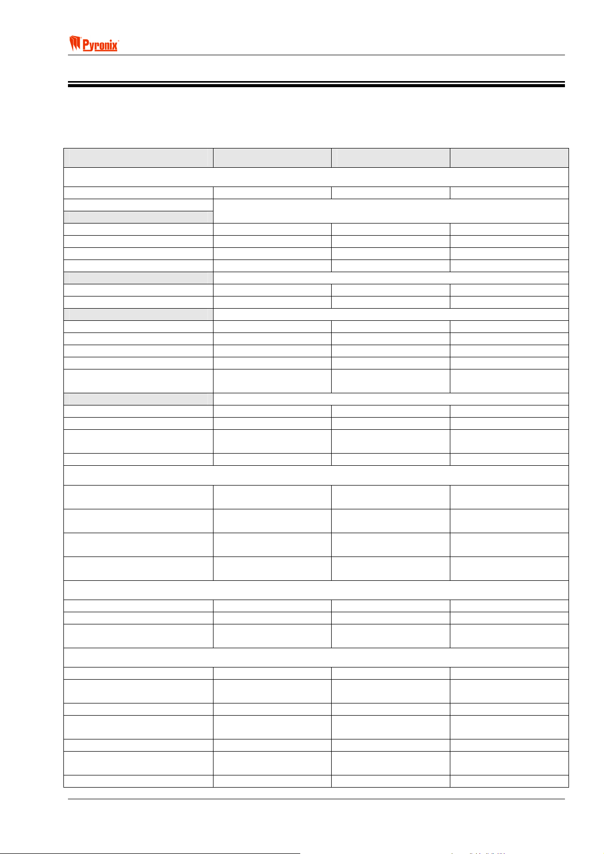
1.1 Technical Specifications
1.1.1 Main Control Panel
Matrix 832+ Matrix 832 Matrix 424
ZONES
Zone Loop Current
Zone Activation Resistance
DEOL
Short circuit
Normal
Activated
Open circuit
Normally Closed
Normal
Activated
Doubled
Both zones Normal
Both zones Activated
Zone n Activated
Zone n+16 Activated
Zone Doubled: Tamper
Activated
Zone Response Time
Standard Zones
Fast Zones
Only Zone 1 Fast
Zone Protection
0.54mA - Max 0.54mA - Max 0.54mA - Max
<800Ω <800Ω <800Ω
>800Ω to <6kΩ >800Ω to <6kΩ >800Ω to <6kΩ
>6kΩ to <36kΩ >6kΩ to <36kΩ >6kΩ to <36kΩ
>36kΩ >36kΩ >36kΩ
<4kΩ <4kΩ <4kΩ
>4kΩ >4kΩ >4kΩ
>2kΩ to <6kΩ >2kΩ to <6kΩ >2kΩ to <6kΩ
>11kΩ to <35kΩ >11kΩ to <35kΩ >11kΩ to <35kΩ
>8kΩ to <11kΩ >8kΩ to <11kΩ >8kΩ to <11kΩ
>6kΩ to <8kΩ >6kΩ to <8kΩ >6kΩ to <8kΩ
<2kΩ or >35kΩ <2kΩ or >35kΩ <2kΩ or >35kΩ
350ms 350ms 350ms
100 ms 100 ms 100 ms
Zone1 - 30ms
Other zones - 350ms
18V Varister 18V Varister N/A
PROGRAMMABLE OUTPUTS (PGM)
PGM 1
PGM 2
PGM 3
PGM 4
Relay contacts
30V@3A
Relay contacts
30V@3A
Open Collector
12V@200mA
Open Collector
12V@10mA
DIGITAL COMMUNICATOR
Telephone Line Monitoring
Digital Communicator
Lightning Protection
Yes Yes Yes
Analogue Line Analogue Line Analogue Line
Heavy duty protection
6.75kV / 125A
POWER SUPPLY
Power Input
Transformer Rating
EN50131-6 Type
Voltage Output
Ripple
Total Current Output
AUX, Bell, K+
Panel Current Requirement
17Vac 17Vac 17Vac
44VA (Metal case)
21VA (Plastic case)
A A A
13.6Vdc@1A regulated
Max 13.8V Min 10.5V
1% Max. 1% Max 1% Max
600mA (Plastic)
1.1A (Metal)
200mA 200mA 200mA
Zone1 - 30ms
Other zones - 350ms
Relay contacts
30V@3A
Open Collector
12V@200mA
Open Collector
12V@ 200mA
Open Collector
12V@10mA
Heavy duty protection
6.75kV / 125A
21VA 21VA
13.6Vdc@1A regulated
Max 13.8V Min 10.5V
600mA 600mA
Zone1 - 30ms
Other zones - 350ms
Relay contacts
30V@3A
Open Collector
12V@200mA
Open Collector
12V@200mA
Open Collector
12V@10mA
Heavy duty protection
6.75kV / 125A
13.6Vdc@1A regulated
Max 13.8V Min 10.5V
RINS428-5 Page 1

Matrix 832 / 832+ / 424
Matrix 832+ Matrix 832 Matrix 424
FUSES
Bell fuse
Aux fuse
Keypad fuse
Battery fuse
Quick blow 1A – F1L Quick blow 1A – F1L Quick blow 1A – F1L
Quick blow 1A – F1L Quick blow 1A – F1L N/A
Quick blow 1A – F1L N/A N/A
Slow blow 5A – T5H N/A N/A
BATTERY
Type
Battery Charge
Maximum Battery Charge
Current
Battery Charge Method
Battery Capacity
BAT Terminal Protection
Low Battery Detect Level
Battery Cutoff Level
12V Lead acid
rechargeable
Min 6V Min 6V Min 6V
800mA (Metal Case)
350mA (Plastic case)
12V Lead acid
rechargeable
350mA 350mA
The Matrix panel monitors the voltage of the battery and commences
charging when the battery reaches 12.8V +/- 5% and disables charging
when it reaches 13.6V +/- 5%.
Metal Enclosure
2.8 to 17Ah
Plastic Enclosure
2.8 to 7Ah
Plastic Enclosure
2.8 to 7Ah
Short circuit & battery
reverse protection.
Short circuit & battery
reverse protection.
10.7V +/- 0.2V 10.7V +/- 0.2V 10.7V +/- 0.2V
10.4V +/- 0.2V
(With MX-BATT)
10.4V +/- 0.2V
(With MX-BATT)
12V Lead acid
rechargeable
Plastic Enclosure
2.8 to 7Ah
Short circuit & battery
reverse protection.
10.4V +/- 0.2V
(With MX-BATT)
MECHNICAL
Security Grade
Environmental Class
Dimensions
Plastic
Metal
2 (Metal Case)
N/A (Plastic Case)
2 (Metal Case)
N/A (Plastic Case)
340 x 280 x 94.5 mm 340 x 280 x 94.5 mm 340 x 280 x 94.5 mm
389.5 x 314.5 x
96.2mm
N/A N/A
N/A N/A
N/A N/A
TEMPERATURE
Operational Metal Case
-10 to +55ºC
14 to 131ºF
Plastic Case
0 to +40ºC
32 to 104ºF
Storage
-20 to +60ºC
-4 to 172ºF
Maximum Humidity
93% Rh (Metal Case) N/A N/A
0 to +40ºC
32 to 104ºF
-20 to +60ºC
-4 to 172ºF
0 to +40ºC
32 to 104ºF
-20 to +60ºC
-4 to 172ºF
Page 2 RINS428-5
! Matrix 832 / 832+ / 424
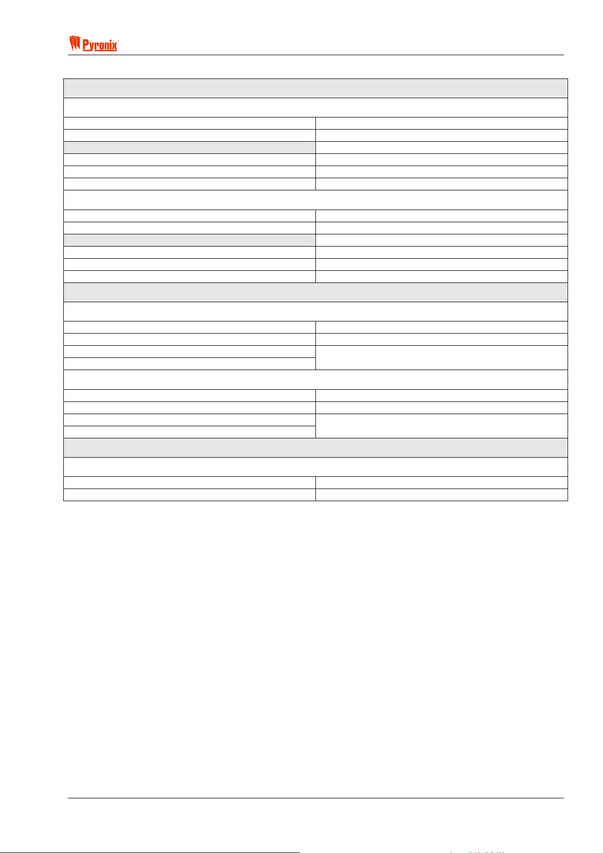
1.1.2 Additional Expanders
PROGRAMMABLE OUTPUT EXPANDERS
TRANSISTOR MX-ROX8T
Supply Voltage
Supply Current
Outputs
Type
Maximum Switching Voltage
Maximum Switching Current
RELAY MX-ROX8R
Supply Voltage
Supply Current
Outputs
Type
Maximum Switching Voltage
Maximum Switching Current
PROGRAMMABLE ZONE EXPANDERS
LOCAL PLUG-ON MX-IX16
Supply Voltage
Supply Current
Zone Loop Current
Zone Activation Resistance
REMOTE MX-RIX with Zone Analyser
Supply Voltage
Supply Current
Zone Loop Current
Zone Activation Resistance
PROGRAMMABLE VOICE MODULE
13.8V typical (9-16V range)
45mA +/- 5 % @13.8V
Open Collector
12Vdc
225mA
13.8V typical (9-16V range)
225mA +/- 5 % @13.8V
N/O / N/C contacts
30V
1A
13.8V typical (9-16V range)
15mA@ +/- 5 % 13.8V
See main control panel data
12V typical (9-16V range)
45mA +/- 5 % @13.8V
See main control panel data
MX-VOICE
Supply Voltage
Supply Current
13.8V typical (9-16V range)
25mA +/- 5 % @13.8V
RINS428-5 Page 3

Matrix 832 / 832+ / 424
1.2 Battery Capacity Calculations
Maximum Battery recharge time must not exceed 72 hours to satisfy EN50131-6.
1.2.1 UK Requirements
In the event of mains failure BS4737 Part 1, Section 7.2.1, specifies that a stand-by battery should be able to
power the system for a non-alarmed period of 8 hours. The typical Local Authority specified maximum bell
alarm period is 20 minutes.
Example Calculation
Non-alarmed condition 7 hrs 40mins = 7.67Hrs:
Control panel 0.130A
Keypad 0.015A
Detectors (8 detectors at 15mA each) 0.120A
External sounder 0.050A
External strobe 0.000A
Total current 0.315A
Amp/hour capacity 0.315A x 7.67h = 2.41Ah
Alarmed condition 20mins = 0.33Hrs:
Control panel 0.130A
Keypad 0.015A
Detectors (8 detectors at 15mA each) 0.120A
External sounder 0.350A
External strobe 0.150A
Total current 0.765A
Amp/hour capacity 0.765A x 0.33h = 0.25Ah
Minimum battery capacity = 2.41A + 0.25A 2.66Ah
WARNING: Consult each product’s instructions for the actual current values.
1.2.2 Norwegian & Danish Requirements
Required capacity = (18 x A) + (0.5 x B)
Where:
A = Maximum non-alarmed total system current.
B = Maximum alarmed total system current.
1.2.3 Swedish Requirements
Required capacity = 12 x A
Where:
A = Maximum total system current.
Page 4 RINS428-5

! Matrix 832 / 832+ / 424
1.3 System Overview
Matrix 832 / 832+ Matrix 424
ZONES
Zones on Main Board
Zone Expander (On Board)
MX-RIX with Zone Analyser
8 fully programmable zones on
Maximum Zones Capacity
Zone Configurations
Zone Types
Zone Attributes
PROGRAMMABLE OUTPUTS
PGM On-Board
Outputs
8 fully programmable zones (16
using zone doubling option)
8 fully programmable zones on local
plug In expander (16 using zone
doubling option)
remote expander (16 using zone
doubling option)
32 zones using zone doubling
option and zone expander
1. Normally closed
2. DEOL – 2 end of line resistors
3. Zone doubling – 1 end of line
resistor
1. Entry / Exit
2. Access
3. Immediate
4. Medical
5. Arm
6. Omitted (Bypassed)
7. Fire
8. PA
9. 24hr
10. Key box
11. Shunt keypad
12. Tamper
13. Key switch Latched
14. Key switch Momentary
15. Unused
1. Chime
2. Test
3. Mask
4. Double knock
5. Normally Open
6. Normally Closed
1. PGM1 – N/O / N/C
2. PGM2 –
(832+) N/O / N/C
(832) Active High / Active Low
3. PGM3 – Active High / Active
Low
4. PGM4 – Active High / Active
Low
4 fully programmable zones (8 using
zone doubling)
8 fully programmable zones on local
plug In expander (16 using zone
doubling option)
Not Available
24 zones using doubling option and
zone expander
1. Normally closed
2. DEOL – 2 end of line resistors
3. Zone doubling – 1 end of line
resistor
1. Entry / Exit
2. Access
3. Immediate
4. Medical
5. Arm
6. Omitted (Bypassed)
7. Fire
8. PA
9. 24hr
10. Key box
11. Shunt keypad
12. Tamper
13. Key switch Latched
14. Key switch Momentary
15. Unused
1. Chime
2. Test
3. Mask
4. Double knock
5. Normally Open
6. Normally Closed
1. PGM1 – N/O / N/C
2. PGM2 – Active High / Active Low
3. PGM3 – Active High / Active Low
4. PGM4 – Active High / Active Low
NOTE: Active High switches from 0V to 12V; Active Low switches from 12V to 0V.
RINS428-5 Page 5

Matrix 832 / 832+ / 424
Matrix 832 / 832+ Matrix 424
PGM Options
PGM Expander MX-ROX
Outputs
1. Off
2. PIR remote LED enable (E-)
3. PIR Latch memory (C+)
4. Follow Arm / Disarm
5. Follow zone
6. Follow line fail
7. Follow kiss off
8. Shock / Fire reset
9. Follow strobe
10. Follow Fire Alarm
11. Follow PA
12. Confirmed Alarm
13. Follow Tamper Alarm
14. External Bell
15. GND Fire detector – PGM 4 only
16. Twin Alert – PGM 3 only
17. Follow entry exit
18. Follow Digi Com - Fire Signal
19. Follow Digi Com - PA Signal
20. Follow Digi Com - Intruder Signal
21. Follow Digi Com - Open/Close
22. Follow Digi Com - Spare Signal
23. Follow Digi Com - Medical Signal
24. Follow Digi Com - Conf Signal
25. Follow Digi Com - Omits Signal
26. Follow Hidden Display
27. Follow Mains Fail
28. Follow Battery Low
29. Follow Battery Missing
30. Internal Sounder
1. 8 open collector – Installable
remotely on keypad bus
2. 8 relay expander – installable
remotely on keypad bus
KEYPADS
Type
Dedicated buttons
Max number
Settings
LCD Keypad
Supply Voltage
Supply Current
LED Keypad
Supply Voltage
Supply Current
ICON Keypad
Supply Voltage
Supply Current
1. Two 7 segments LED
2. LCD 32 character
3. ICON
1. PA
2. Fire
3. Medical
Four of same type (max 6 devices) Four of same type (max 6 devices)
1. Private - system status indicated
during arming
2. Public - system status indicated
in arm mode
3. Hidden - display suppressed after
20 seconds
9-16Vdc 9-16Vdc
80mA – Normal
20mA – Minimum brightness setting
9-16Vdc 9-16Vdc
60mA Maximum @ 13.8V 60mA Maximum @ 13.8V
9-16Vdc 9-16Vdc
50mA Maximum @ 13.8V 50mA Maximum @ 13.8V
1. Two 7 segments LED
2. LCD 32 character
3. ICON
1. PA
2. Fire
3. Medical
1. Private - system status indicated
during arming
2. Public - system status indicated
in arm mode
3. Hidden - display suppressed after
20 seconds
80mA – Normal
20mA – Minimum brightness setting
Page 6 RINS428-5

! Matrix 832 / 832+ / 424
Matrix 832 / 832+ Matrix 424
PROXIMITY READER (Not approved for use in Denmark, Norway, Finland or Sweden)
Type
Max number
Settings
Supply Voltage
Supply Current
Inductively coupled key-fob or card Inductively coupled key-fob or card
Four of same type (max 6 devices) Four of same type (max 6 devices)
1. Private – system status indicated
during arming
2. Public – system status indicated
in arm mode
1. Private – system status indicated
during arming
2. Public – system status indicated
in arm mode
9-16Vdc 9-16Vdc
Max 90mA@13.8V Max 90mA@13.8V
PARTITIONS
Number of partitions
Independent settings
Arm modes
Home / Away allocation
Arming options
Timers
Real time clock
4 true partitions with common option 4 true partitions with common option
1. Zones
2. Keypads
3. Proximity readers
4. User codes
5. PGMs
6. Timers
7. Reporting account codes
1. Zones
2. Keypads
3. Proximity readers
4. User codes
5. PGMs
6. Timers
7. Reporting account codes
4 arm modes per partition (A, B, C, D) 4 arm modes per partition (A, B, C, D)
Programmable individual arm modes Programmable individual arm modes
1. Final door
2. Timed exit
3. Silent arm
4. Forced Arm
1. Entry / Exit
2. Bell Delay
3. AC Fault Delay
4. Telephone Line Fault Delay
5. Inactivity Arm Time 10-990min
6. Auto Arm – Time of Day
7. Final Exit Delay
8. Quartz Correction Factor
9. Confirmed Alarm
1. AC frequency Based
2. Quartz Based
1. Final door
2. Timed exit
3. Silent arm
4. Forced Arm
1. Entry / Exit
2. Bell Delay
3. AC Fault Delay
4. Telephone Line Fault Delay
5. Inactivity Arm Time 10-990min
6. Auto Arm – Time of Day
7. Final Exit Delay
8. Quartz Correction Factor
9. Confirmed Alarm
1. AC Frequency Based
2. Quartz Based
USER CODES
Number of user codes
User code types
32 codes (4 to 6 digits) 32 codes (4 to 6 digits)
1. Master user per partition
2. Limited user
3. Duress
4. Engineer
5. Arm only - can be used as a
patrol code
6. Disarm only - can be used as a
patrol code
7. Omit (Bypass)
8. Temporary
9. Limited number of uses
1. Master user per partition
2. Limited user
3. Duress
4. Engineer
5. Arm only - can be used as a
patrol code
6. Disarm only - can be used as a
patrol code
7. Omit (Bypass)
8. Temporary
9. Limited number of uses
CENTRAL MONITORING OPTIONS
Telephone Numbers
Communication Protocols
9 telephone numbers shared with
pager, Pyronix PC format and digital
communication formats
1. Contact ID
2. Pager Format
3. BSIA Fast Format
4. Pyronix PC Format
5. MX Voice
9 telephone numbers shared with
pager, Pyronix PC format and digital
communication formats
1. Contact ID
2. Pager Format
3. BSIA Fast Format
4. Pyronix PC Format
5. MX Voice
RINS428-5 Page 7

Matrix 832 / 832+ / 424
CENTRAL MONITORING OPTIONS – Cont.
Group Reporting to CMS
Programmable Send
Options
Test Call
Telephone Line Monitoring
Telephone Connection
Digital Communicator
Lightning Protection
1. Events sent to 1 number only
2. Events sent to 2 numbers
3. Events sent to first number with
backup of second number
1. In disarmed mode
2. In arm modes A, B, C and D
3. Restorals
4. Alarms
5. PAs
6. Fire
7. Maintenance
8. Open / Close
9. Medical
Programmable in days, hours and
minutes
Yes – with status indication Yes – with status indication
Allows other telephone on the line Allows other telephone on the line
Analogue line Analogue line
Heavy duty lightning protection
6.75kV/125Amps
1. Events sent to 1 number only
2. Events sent to 2 numbers
3. Events sent to first number with
backup of second number
1. In disarmed mode
2. In arm modes A, B, C and D
3. Restorals
4. Alarms
5. PAs
6. Fire
7. Maintenance
8. Open / Close
9. Medical
Programmable in days, hours and
minutes
Heavy duty lightning protection
6.75kV/125Amps
OTHER
Software Support
Memory Event Log
1. UDL programming software
2. Pyronix MX-MON software to be
used with:
a. Modem + Pyronix format
b. RC12/RC112 +
Contact ID/BSIA
300 events with time and date
Log deletion cannot be allowed either
accidentally or on purpose.
Log reaction time is more than 30
days and the clock will not change
more than + / - 10 mins over 1 year at
20c
1.3.1.1 Minimum Installation Requirements
In addition to the main alarm panel (424, 832 or 832+), and any detectors or sensors, at least one keypad is
required. This can be an LCD, LED or ICON keypad. One keypad MUST be set to ID-1. This is the minimum
requirement.
1.3.1.2 Installation Constraints
A maximum of 6 devices can be attached to the Matrix bus (see also Section 4: Cabling Rules for the Matrix
Bus). The following table shows the maximum number of each device type allowable, whilst at the same time
remembering that only 6 devices in total can be on the bus at any one time.
BUS DEVICE MATRIX 832+ /832 MATRIX 424
LCD Keypad 4 4
ICON Keypad 4 4
MX-PROX Proximity Reader 4 4
MX-RIX with Zone Analyser 1 1
On-board Input Expander 1 1
MX-ROX Output Expander 1 1
Page 8 RINS428-5
! Matrix 832 / 832+ / 424
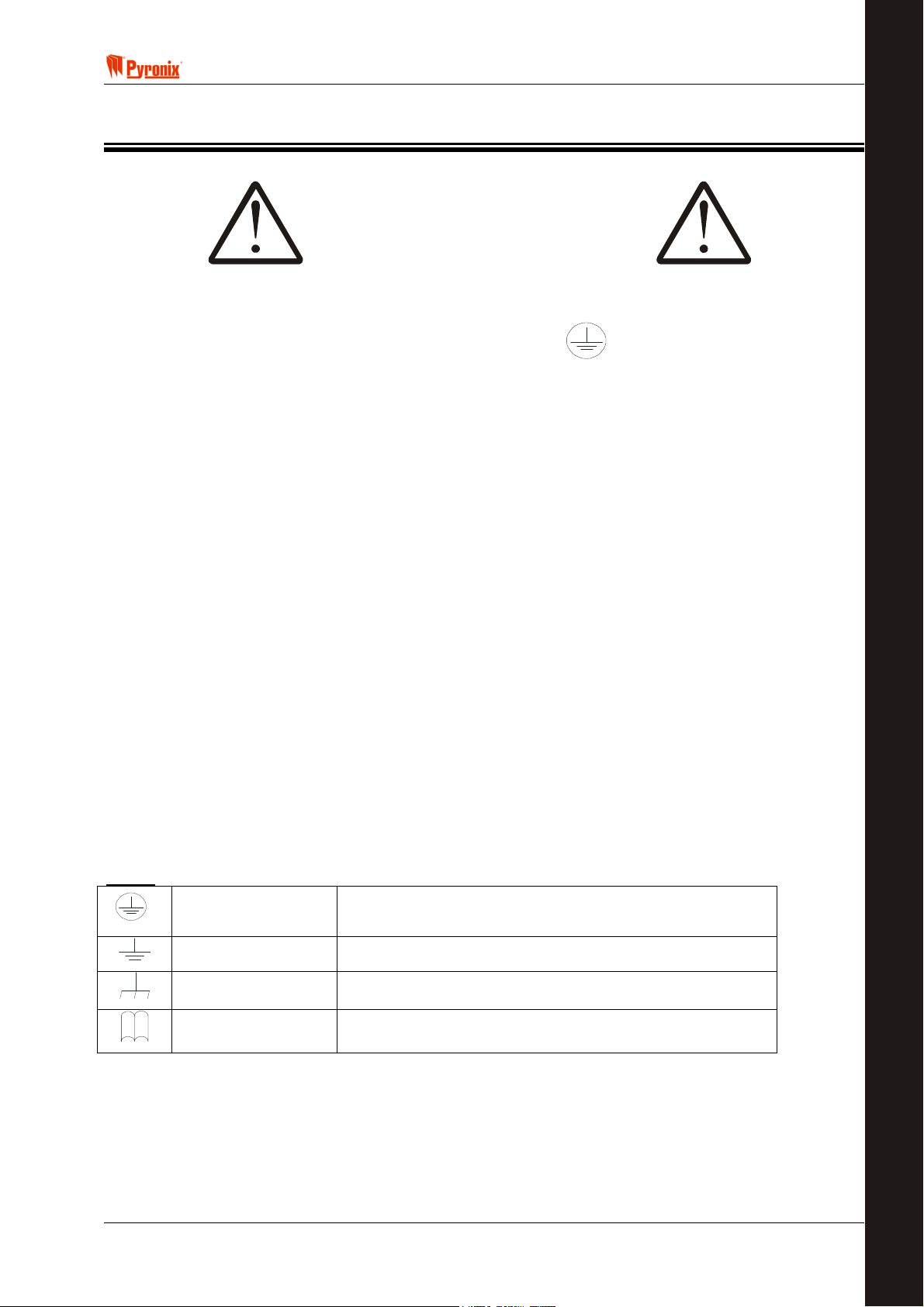
Section 2: Safety & Approvals
SAFETY
1. A technically competent person must carry out the mains installation in accordance with the national and
local electrical installation regulations
E
C
N
A
I
L
P
M
O
C
2. Protective Earth: This equipment must be earthed/grounded
3. Functional Earth: Must be connected to earth terminal to allow the equipment to operate correctly. Has
no safety implications.
4. Connect the unit to a single pole, unswitched, 3 Amp fused spur, using 0.75mm
cannot be positively identified use a double pole disconnect version.
5. Always remove / isolate the mains supply before carrying out any servicing of the panel.
6. Fuses: For continued protection against the risk of fire, replace only with the same type and rating of
fuse.
7. There are no user serviceable parts inside the equipment.
8. This unit should be mounted so that there will be no outside access to the electrical cable entry point
9. Ventilation: To ensure the correct airflow, always mount the unit vertically with the unit having a clear
space on all sides. It must not be covered by clothes, furnishings, boxes, etc. It must not be mounted
close to, or above, heat radiating sources.
10. On completion of wiring, use tie-wraps to prevent any loose wires causing a safety hazard.
11. The mechanical mounting of the unit must be secure enough to carry the full weight of the unit including
all batteries.
12. Batteries: Ensure that the battery terminal connections will not create an electrical short-circuit on the
case metalwork when the unit is closed. Use insulated battery lead connectors.
13. Dispose of old batteries as required by environmental legislation / recommendations.
2
cable. If the Neutral
14. The battery case must have a flame-retardant rating of UL94-V2/V1/V0 – IEC60950:2000
15. Water: The equipment must be kept free from dampness, water and any other liquids. It is only suitable
for installation indoors.
ICONS
RINS428-5 Page 9
Protective Earth
Protective Bonding
Functional Earth
Read
Must be connected to the electrical installation earth / ground
Must be connected to the equipment protective earth terminal
Must be connected to earth terminal to allow the equipment
to operate correctly. Has no safety implications.
Read equipment instructions

Matrix 832 / 832+ / 424
Page 10 RINS428-5

! Matrix 832 / 832+ / 424
RINS428-5 Page 11
Matrix 832 / 832+ / 424
The maximum voltage applied to the equipment must not exceed the safety extra low voltage SELV limits
specified in IEC60950 / EN60950 / UL60950 30VDC / 30VAC / 42.4Vpeak
If you need to switch greater voltage, current or power you will require the use of a separate external
switching relay
Page 12 RINS428-5
! Matrix 832 / 832+ / 424
PYRONIX Ltd
Pyronix House
Braithwell Way
Hellaby,
Rotherham
South Yorkshire
S66 8QY
HTTP://www.pyronix.com ENGLAND, UK
______________________________________________________________
EU Declaration of Conformity
Manufacturer: As above
Details of electrical equipment
Model name(s) Matrix 832+ (Plastic & Metal Housing)
MX-ROX8T, MX-ROX8R, MX-RIX with Zone Analyser
LCD, LED, Icon keypads, MX-PROX
Description: Control & Indicating Equipment
Remote expanders, keypads
Directives that this equipment RTTE 99/05/EC
complies with:
Harmonised Standards applied EN50081-1: 1992 Class B
in order to verify compliance EN50130-4: 1995 + A1: 1998
with the Directives: EN301489-1: V1.4.1
EN301489-3: V1.3.1
EN300330-2: V1.1.1
Testing Agency Status ISO/IEC17025 Certificate No Cert.
York EMC Services
Three Lanes End Centre
Methley
Castleford
West Yorkshire
WF10 1PN
KTL, Saxon Way
Priory Park West
Hull, Humberside
HU13 PB9
Year in which CE mark was affixed: 2002
Authorized signatory:
Manufacturer Authorized Representative Date of issue
Testhouse
Testhouse
UKAS 1574
UKAS 0971
EN45014
5212TC
5503/TR/1
5494/TR/1
5430/TR/1
1C5217CEU1
1C521CCB1
2H5972GEU1
Category
Date
02/01/02
01/04/03
20/03/03
02/01/03
01/10/02
11/10/02
21/11/02
EMC
EMC
EMC
EMC
Safety
Safety
Radio
.................................. .............................................. Place of issue
Name: Craig Leivers Not applicable Pyronix Ltd
Position: R & D Director
RINS428-5 Page 13
01 June 03
Matrix 832 / 832+ / 424
Section 3: Mounting Procedure
3.1 Mounting Procedure for Matrix – Plastic & Metal Case
The following steps illustrate basic mounting procedure for matrix plastic & metal case.
(See section 12 for complete wiring diagrams)
Step 1 - Remove the case lid from the matrix panel and check all parts and components are in place.
Step 2 - Decide where the matrix panel will be situated. The matrix panel may be housed in the loft or
different rooms in the premises. A discrete and concealed place is advisable, as only the Matrix keypads need
to be seen.
Step 3 - Secure the matrix panel to a sturdy and stable surface, using the mounting screws provided. First
mark the wall where the panel is to be situated (using the mounting holes), drill holes in the wall, and fasten
the panel base to the wall using the screws supplied.
Step 4 - Before the panel base is completely secured to the wall feed cables for keypads / AC power supply /
and accessories through the cable entry holes as illustrated.
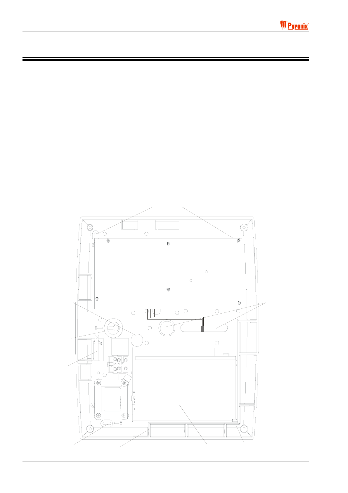
3.2 Panel Layout – Plastic Case
Mains Cable
Entry Hole
Wall Fixing
Hole
Tamper
Switch
Wall Fixing
Holes
Cable Entry
Hole
Transformer
Wall Fixing
Hole
Page 14 RINS428-5
Battery
Support
Battery
Wall Fixing
Hole
! Matrix 832 / 832+ / 424
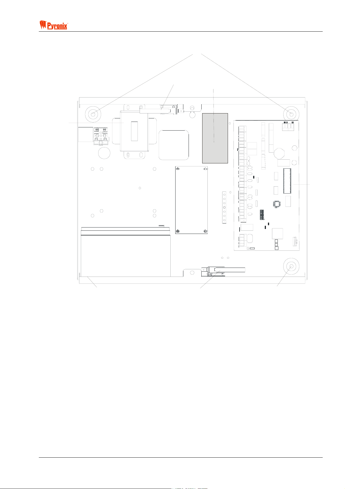
3.3 Panel Layout – Metal Case
Wall Fixing Holes
Transformer
Tam p er S w it c h
MX-Voice
Mo dule
Battery Test Module
(Optional )
PCB
Battery
7Ah - 17Ah
Wall Fixing Ho le
Tam per Sw it c h
Wall Fixing Hole
3.4 Battery Installation Procedure
Place two foam pads on the bottom of the Battery and two on the upper rear. Place the Battery in the case
and secure with two tie wraps.
RINS428-5 Page 15

Matrix 832 / 832+ / 424
Section 4: Cabling Rules for the Matrix Bus
Care must be taken when connecting devices to the bus over long cable runs. This is to ensure maximum
system integrity under all circumstances (battery backup etc.). Pyronix recommends using standard 0.22mm
cross sectional area, unshielded multi-core alarm cable for Matrix installations.
The maximum number of devices connected to the bus on any one system is limited to six - this may
not be exceeded. Although six is the system limit other restrictions apply to each cable run. It is important to
restrict the amount of current carried along each length of cable to limit voltage drops across the system.
Apart from being affected by current magnitude, voltage drops are also dependent upon the length of cable
and the types of devices fitted.
The following tables provide a means of determining suitable cable run configurations for different systems.
NOTE: It is the length of cable between panel and end device that is important rather than the overall
length on the entire bus.
Table 1: ‘KEN’ (Keypad Equivalent Number) values for each serial module
DEVICE Description and Configuration KEN
MX-LCD Matrix LCD Keypad 3
MX-LED Matrix LED Keypad 1
MX-ICON Matrix ICON Keypad 1
MX-RIX with
Zone Analyser
MX_PROX Proximity Reader 2
MX-ROX8R 8 Way Relay Output Module *1 *2 4
MX-ROX8T
MX-ROX8T
MX-ROX8T
MX-ROX8T
MX-ROX8T
*1 The Above KEN assignments for Relay type output modules assume that all power supplying the switched
contacts (devices switched on/off by the output expander) is supplied via a different feed/ PSU.
*2 Remember that the maximum allowable current-draw from the Matrix for External devices is 0.6A. Any
requirement exceeding this must be provided by a separate power supply. Where a power supply is added for
use with an output expander, the 0V of the supply should be connected at the expander. 1+
Table 2: Number of ‘KENs’ Allowed for different Cable lengths.
Matrix Remote Zone Expander.
8 Way Transistor Output Module (max. total transistor
outputs current sink < 30mA)
8 Way Transistor Output Module (max. total transistor
outputs current sink < 90mA)
8 Way Transistor Output Module (max. total transistor
outputs current sink < 150mA)
8 Way Transistor Output Module (max. total transistor
outputs current sink < 210mA)
8 Way Transistor Output Module (max. total transistor
outputs current sink > 210mA)
1
1
2
3
4
1+
Sink Current(A) – 0.03
0.06
Length of Cable
(meters)
100 3 4
75 4 6
50 6 9
25 13 18
Page 16 RINS428-5
Number of KEN allowed with Single
core cable per signal
Number of KENs with standard
cable 0V return doubled (2 cables)
! Matrix 832 / 832+ / 424
4.1 System Examples
A Matrix System is required to provide the following:
6 PIR Detectors (15mA each).
A bell-box (max. current draw 400mA) connected to PGM1.
2 Matrix ICON Keypads (60mA each), one 50m away, and the other 100m away.
A Matrix Transistor Output Expander (30mA) with 3 LEDs (10mA each) and 3 buzzers (12mA each) controlled
by the outputs (accompanying the keypad 100m away) power supply.
From the above example, the total current drawn from the panel would be:
TOTAL Detectors Bell RKPS
0.706A 6 X 0.015 1 X 0.400 2 X 0.050 1 X 0.030 3 X 0.010 3 X 0.012
The maximum current available for external devices from the Matrix PCB is 0.6A. Therefore, this installation
would require an additional power supply.
Before we can calculate an acceptable wiring arrangement we must know the ‘KEN value for each device on
the keypad bus. From Table 1 we know that each keypad has a KEN of 1. The Transistor Output expander
controls the LEDs and buzzers, which together give a total current of 66mA (3x10mA + 3x12mA). From table
1 a transistor output expander with a current sink of 66mA falls into the <90mA criteria which corresponds with
a ‘KEN’ of 2.
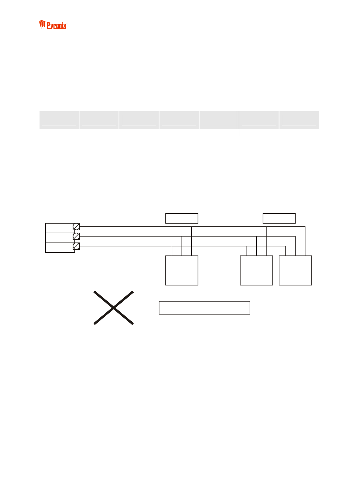
Example 1
The most straightforward wiring approach would be to daisy chain the devices on one run as below.
AUX+/K+
AUX-/K-
50m.
KD
Keypad
1
(1 KEN)
Output
Expander
LEDs Buzzers
100m.
Keypad
2
(1 KEN)
Output
Expander
(2 KEN)
NOT ACCEPTABLE
However, this is an unacceptable solution because there are 4 ‘KEN’ on a 100m length of cable. Table 2
shows that a maximum of 3 ‘KEN’ is acceptable on a 100m length of cable – the fact that one keypad is just
50m away does not affect these rules.
RINS428-5 Page 17

Matrix 832 / 832+ / 424
Example 2
This is now an acceptable solution because the ground return is shared between 2 cores of cable. Referring
to table 2, the second column shows that by doubling up the ground return it is acceptable to have up to 4
‘KEN’ on a 100m length of cable.
100m.
Output
2
Expander
(2 KEN)
AUX+/K+
KD
AUX-/K-
50m.
Keypad
1
(1 KEN)
Keypad
(1 KEN)
ACCEPTABLE SOLUTION
KD
50m.
100m.
Example 3
This is now an acceptable solution because there are now two separate cables connecting the devices back
to the Matrix control panel. The 100m cable is now supporting 3 ‘KEN’ and is now in accordance with table 2,
and the 50m cable is supporting 1 ‘KEN’ which is well within the limits.
AUX+/K+
AUX-/K-
Keypad
2
(1 KEN)
Keypad
1
(1 KEN)
Output
Expander
(2 KEN)
ACCEPTABLE SOLUTION
Page 18 RINS428-5

! Matrix 832 / 832+ / 424
Section 5: Operating Modes
5.1 Disarmed Mode
This is the state of the panel when disarmed. However, Fire, Personal Attack, Medical, Tamper and 24 Hr
inputs remain active 24 hours a day.
5.2 Armed Mode
When the panel is armed an activation of any Access, Immediate or 24 hour zone will cause an alarm
condition. When an alarm condition is generated the internal / external sounders and strobe outputs will
operate for the length of time the panel is programmed, or until the panel is reset by the user.
5.3 Arm Mode
When arming the control panel, any one of four arm modes can be selected. Each of these arm modes (A, B,
C and D) can be programmed with different configurations.
Arm A: Whole system armed, Premises empty–
Away.
Arm B: Upstairs disarmed, downstairs armed –
Home
Arm C: Upstairs armed, downstairs disarmed –
Home
Arm D: Garage armed, the house disarmed – Home
5.4 Entry / Exit Mode
Entry - When the panel is armed and an Entry zone is triggered the Entry timer will begin to countdown.
During this period an Entry / Exit tone (Single repeated bleep) will be produced by the internal sounder and
any zones which are programmed as Access zones will be ignored. If a correct user code is entered before
the end of the count down period the panel will return to disarmed mode. If the timer is allowed to elapse
before a user code is entered the panel will go into alarm state, in this case the system needs to be disarmed,
and will enter FTA mode (See below) disarmed.
Exit - Timed Exit, Silent Exit, Final Exit - Matrix control panels use different types of exit procedures. The
most popular exit type used is Timed Exit that can operate in two different ways depending on how the Global
System Options 2 are programmed: Procedure 1 - from disarmed mode enter user code. The panel will start
arming. If any zones are open then the exit timer will be delayed until the relevant zones are closed. At the
end of exit time and providing that all zones have been closed the panel will arm. Procedure 2 - from
disarmed mode enter user code. If any zones are open except Entry / Exit and Access the panel will give an
error tone and come back to disarmed mode. If all zones are closed except Entry / Exit and Access the panel
will start arming. If the Entry / Exit and Access zones are still open at the end of the exit time the panel will go
into alarm. If these are closed then it will arm. If during arming time an Immediate zone is open then the panel
will go into alarm.
5.5 Alarm Mode
With the panel in “Disarmed” or “Armed” mode, any of the 24h zones triggered by the system will be put into
alarm condition. With the panel in “Armed” mode, any of the Immediate zones triggered by the system will be
put into alarm condition.
5.6 Anti-Code Reset
After an alarm activation the user may disable the siren and bell only, to reset the system fully the user must
enter an anti-code. The seed code is a randomly generated 5-digit number displayed on the keypad, the seed
code should be given to whoever holds the anti-code generator, who in turn will provide a 4 digit anti-code,
which when entered will reset the panel. As a means of identifying the system, the installer can program the
first digit of the seed code.
RINS428-5 Page 19

Matrix 832 / 832+ / 424
5.7 First to Alarm Mode
When the system is in alarm mode it resets either automatically or by entering a valid user code. When the
system is reset entering the user code the first zone to alarm will be displayed on the display. One further
user code entry will clear the FTA and reset the panel to disarmed mode.
5.8 Engineer Mode
Engineer Mode gives total access to the programming facilities of the system to the engineer using the
engineer code.
5.9 User Mode
User mode allows arming / disarming of the panel and access to the user menu (See the user guide for user
programming instructions).
Page 20 RINS428-5
! Matrix 832 / 832+ / 424
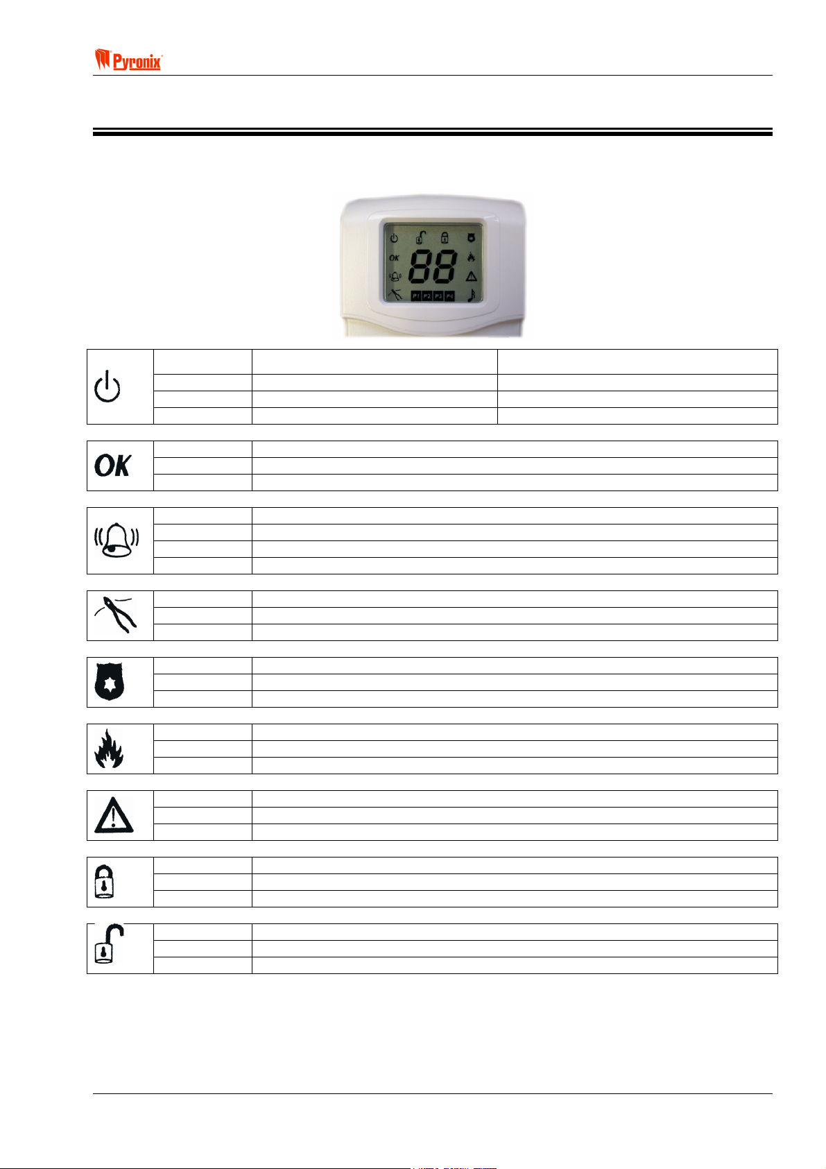
Section 6: Keypad/Reader Symbols & Indications
6.1 The ICON Keypad
Illuminated Correct AC & DC power sources AC power is OK
Blinking Indicates DC source (battery) fault Indicates an AC fault
Extinguished Indicates AC fault / no power to panel No power to the panel
Illuminated OK to Arm, no open zones
Blinking Select partitions to arm or disarm / Programming function is active
Extinguished One or more open zones or all assigned partitions are already armed
Illuminated In Log display qualifies the alarm type / Day mode indicates activated test zone
Slow Blinking Active alarm in FTA mode.
Fast Blinking A latched alarm is active (Denmark, Norway, Finland & Sweden only)
Extinguished No active alarms
Illuminated Indicates a tamper condition (used in log display)
Blinking Indicates a tamper condition in FTA mode
Extinguished No tamper alarm active
Illuminated Indicates a PA alarm condition (used in log display)
Blinking Indicates a PA alarm condition in FTA mode
Extinguished No PA active
Illuminated Indicates a Fire alarm condition (used in log display)
Blinking Indicates a Fire alarm condition in FTA mode
Extinguished No Fire alarm active
Illuminated
Blinking
Extinguished
Illuminated The panel is armed
Blinking Indicates the panel is arming with omitted zones
Extinguished The panel is not armed
Illuminated The panel is disarmed
Blinking Keypad is in user menu mode
Extinguished The panel is not disarmed
Indicates a system Fault
Keypad is in Engineer Mode
No Fault active
Rest of the World Denmark, Norway, Finland & Sweden
RINS428-5 Page 21
Matrix 832 / 832+ / 424
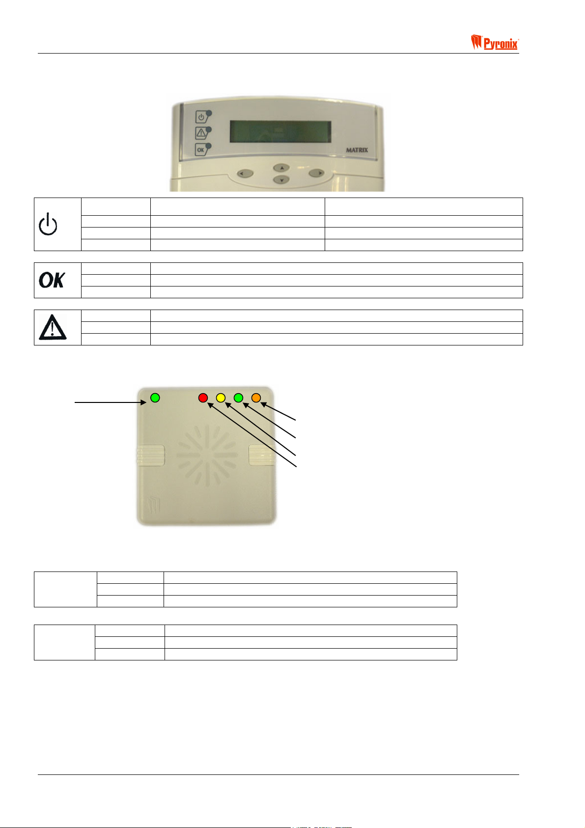
6.2 The LCD Keypad
Illuminated Correct AC & DC power sources AC power is OK
Blinking Indicates DC source (battery) fault Indicates an AC fault
Extinguished Indicates AC fault / no power to panel No power to the panel
Illuminated OK to Arm, no open zones
Blinking Select partitions to arm or disarm / Programming function is active
Extinguished One or more open zones or all assigned partitions are already armed
Illuminated Indicates a system Fault
Blinking Engineer Mode active
Extinguished No Fault active
Rest of the World Denmark, Norway, Finland & Sweden
6.3 The Proximity Reader
Supply
Partition 1 Arm mode A
Status LEDs
Illuminated Correct AC & DC power sources
Supply
Status
LEDs
Blinking Indicates DC source (battery) fault
Extinguished Indicates AC fault / no power to panel
Illuminated Partition or Arm mode is Armed
Blinking Partition or Arm mode is in Alarm
Extinguished Partition or Arm mode is Disarmed
Multipartition Single Partition
Partition 4 Arm mode D
Partition 3 Arm mode C
Partition 2 Arm mode B
Page 22 RINS428-5
! Matrix 832 / 832+ / 424
A
S
Section 7: Programming the System
This section of the manual details how to program all of the Matrix features through PC software and Engineer
Mode functions.
NOTE: The Programming procedure is the same for the Matrix 832+, 832 & 424
Examples of both the PC software and ICON/LCD keypad functionality are shown with explanations of all the
programming options (PC software can be downloaded from the Pyronix web site at www.pyronix.com).
The following key is used in each of the programming sections to show the following functionality.
PC Programming Procedure
MEANING
Programmable Options Explanation
ARMED
ALARM
FAULT
SUPPLY
FIRE
8
8
P.A.READY
TAMPER
DAY
2134
BCD
ET
P.A.
5678
FIRE
FUNC
90
Keypad Programming Procedure
IMPORTANT:
1. Before commencing with any of the programming procedures each of the individual keypads and
proximity readers must be allocated an ID number using the switch on the back of each keypad. (See
Section 8.1/8.2 “Switch settings for keypads & proximity readers”). The Matrix panel recognizes each
device by the allocated device type and ID.
2. All the programming options are shown on the two 7-segment displays for the ICON keypad, and on the
character display for the LCD keypad, during the programming procedures.
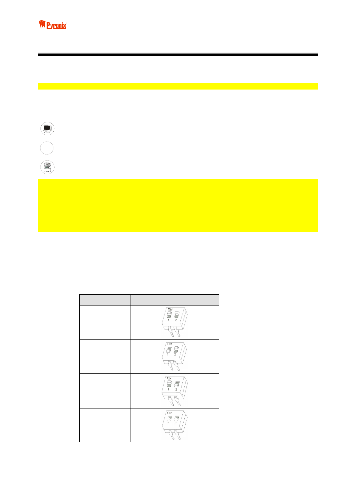
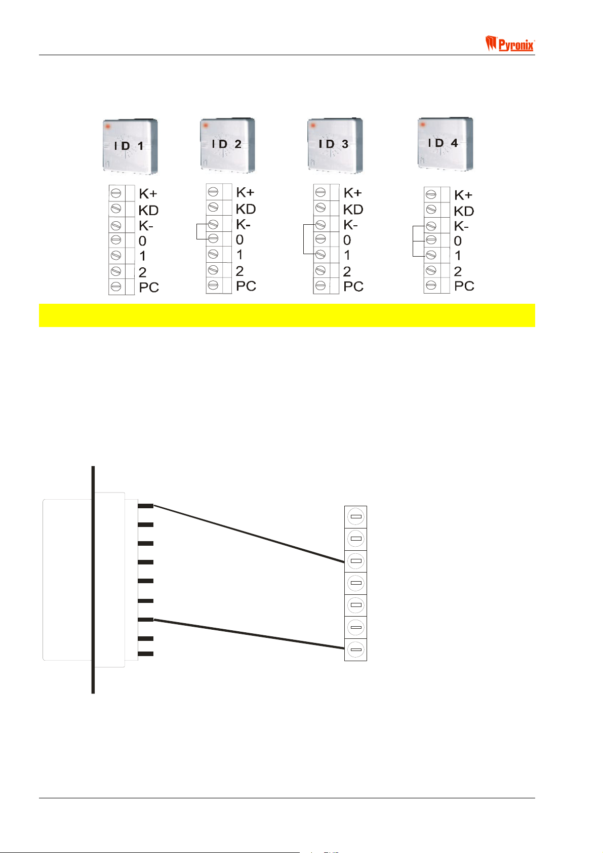
7.1 Addressing the LCD & ICON Keypads
The LCD and ICON keypads are individually addressable. Each keypad type (LCD & ICON) can have four
different addresses. The address of the device is set using the small switch on the keypad PCB. If you have
multiple devices of the same type then they must have different addresses (IDs). One keypad MUST be set to
ID 1
You will need to remove the rear cover from the keypad to gain access to the address switch.
Address (ID) Switch Setting
1
2
3
4
RINS428-5 Page 23
Matrix 832 / 832+ / 424
7.2 Addressing the Proximity Reader
The Matrix panel recognizes individual MX PROX readers by the link settings on the back of each MX PROX
reader.
NOTE: Before you start programming the system, use engineers function 754 to scan for all devices
on the Matrix bus.
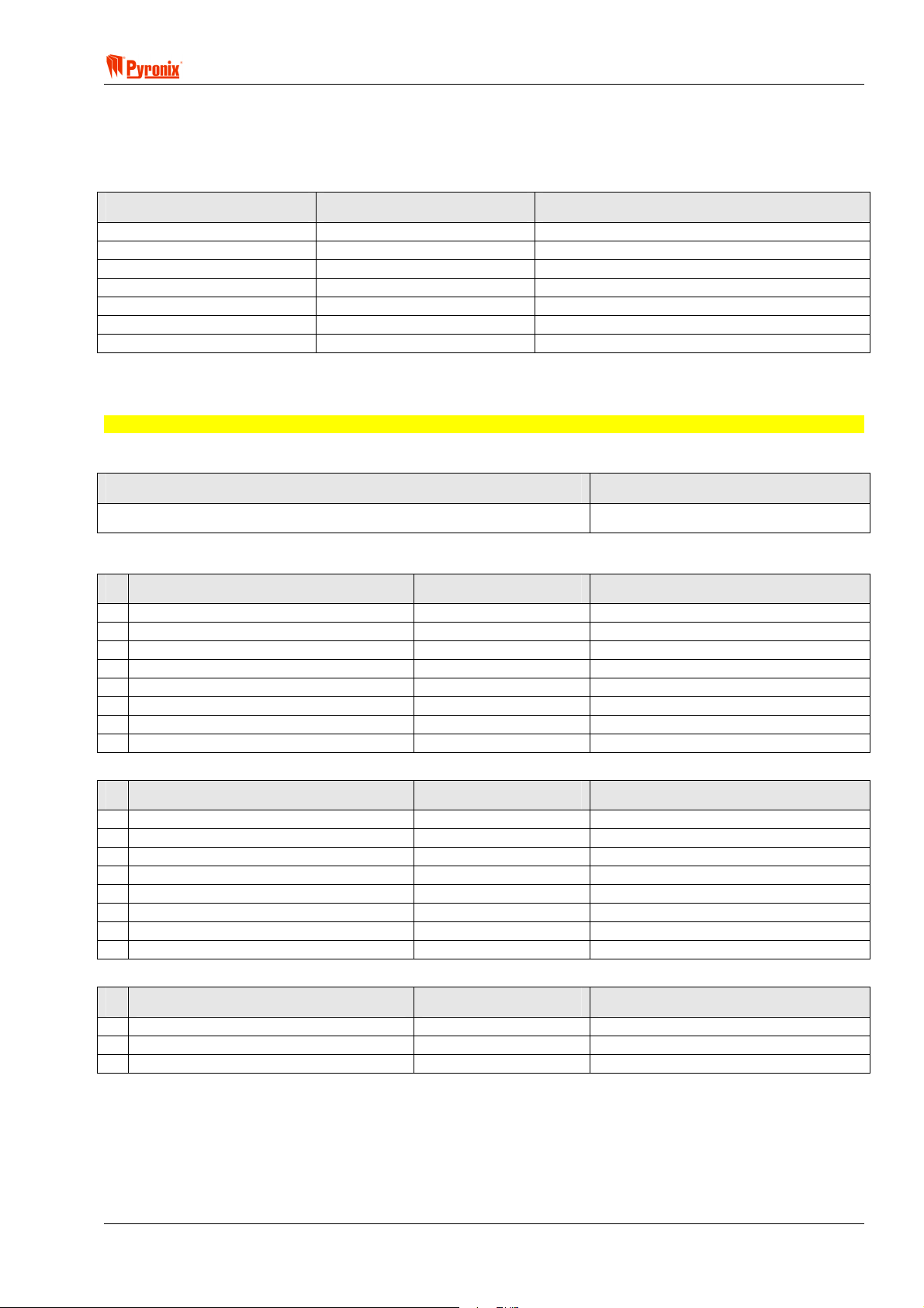
7.2.1 Connection of MX PROX to a PC
As well as programming the proximity cards using the keypad and prox reader, it is also possible to allocate
proximity cards to user codes using a PC. The proximity reader MX PROX should be connected to the PC
serial communication port as shown on the diagram below.
K+ should be connected to +12V.
K- should be connected to pin No 5 & 0V.
PC should be connected to pin No 2.
For information regarding the programming procedure from PC see Section 8.7.
5
9
4
8
3
7
K+
KD
K0
+12V
0V
1
2
6
1
2
PC
MX PROX CONNECTORS
PC 9-Pin DTE
Proximity cards are programmed using a combination of the keypad and the reader. See User Manual
Function 30 for more details.
Page 24 RINS428-5
! Matrix 832 / 832+ / 424
7.3 Finding Bus Devices
Every time you add or remove a device on system bus, you must rescan for bus devices, so that the panel
can recognise the new hardware. See page 99 for more details.
LH Digit – (Type) RH Digit – (ID) Device Type
0 1-4 LCD Keypad
1 1-4 ICON Keypad
2 1-4 Proximity card reader
3 1-4 4-Way output expander
4 1-4 8-Way output expander
5 1-4 4-Way Zone expander / Input Analyser
6 1-4 8-Way Zone expander / Input Analyser
7.4 Factory Default Settings of Matrix System
NOTE: This section provides default settings for Matrix 832, 832+ & 424 control panels.
7.4.1 Engineer Code
Engineer Code Notes
9999
7.4.2 Global System Options
System Options 1 Default Notes
1 AC Fail Warning Enabled
2 Battery Monitoring Enabled
3 NVM Reset Link Only
4 Log and Event Reporting No Limit
5 Alarm in Tel Line Fail Disabled
6 Global Tamper Alarm 0V Removed
7 AC Frequency 50Hz
8 Real Time Clock Mains
System Options 2 Default Notes
1 Tamper Alarm on Device Missing Enabled
2 Put Zone Restorals in the Log Enabled
3 Engineer Lockout when Armed Disabled
4 Allow arm if H, P, I, F, M Zones Open Enabled
5 Immediate Zones Open on Exit Does not cause alarm
6 Suspend Exit Timer on Open Zone Enabled
7 Bell / Global Tamper Inputs Normally Closed
8 Proximity User Code Disarm No limit
System Options 3 Default Notes
1 Hide Display Never
2 Restore Battery Faults As they occur
3 Display Alarm Only if panel disarmed
RINS428-5 Page 25

Matrix 832 / 832+ / 424
Zone Types Default Notes
1 Zones Normally Closed
2 Zone Doubling Disabled
3 Fast Zones Disabled
4 Zone 1 Fast Zone Disabled
Zone Attributes Default Notes
1 Chime Disabled
2 Test Disabled
3 Mask Disabled
4 Double Knock Disabled
5 Normally Open Disabled
7.4.3 Zone Types, Zone Attributes & Zone Settings
Zone Settings
Zone Arm A Arm B Arm C Arm D Attribute Partition
Z01
Z02
Z03
Z04
Z05
Z06
Z07
Z08
Z09
Z10
Z11
Z12
Z13
Z14
Z15
Z16
Z17
Z18
Z19
Z20
Z21
Z22
Z23
Z24
Z25
Z26
Z27
Z28
Z29
Z30
Z31
Z32
Entry/Exit Entry/Exit Entry/Exit Entry/Exit Off 1
Immediate Immediate Immediate Immediate Off 1
Immediate Immediate Immediate Immediate Off 1
Immediate Immediate Immediate Immediate Off 1
Immediate Immediate Immediate Immediate Off 1
Immediate Immediate Immediate Immediate Off 1
Immediate Immediate Immediate Immediate Off 1
Tamper Tamper Tamper Tamper Off 1
Immediate Immediate Immediate Immediate Off 1
Immediate Immediate Immediate Immediate Off 1
Immediate Immediate Immediate Immediate Off 1
Immediate Immediate Immediate Immediate Off 1
Immediate Immediate Immediate Immediate Off 1
Immediate Immediate Immediate Immediate Off 1
Immediate Immediate Immediate Immediate Off 1
Immediate Immediate Immediate Immediate Off 1
Immediate Immediate Immediate Immediate Off 1
Immediate Immediate Immediate Immediate Off 1
Immediate Immediate Immediate Immediate Off 1
Immediate Immediate Immediate Immediate Off 1
Immediate Immediate Immediate Immediate Off 1
Immediate Immediate Immediate Immediate Off 1
Immediate Immediate Immediate Immediate Off 1
Immediate Immediate Immediate Immediate Off 1
Immediate Immediate Immediate Immediate Off 1
Immediate Immediate Immediate Immediate Off 1
Immediate Immediate Immediate Immediate Off 1
Immediate Immediate Immediate Immediate Off 1
Immediate Immediate Immediate Immediate Off 1
Immediate Immediate Immediate Immediate Off 1
Immediate Immediate Immediate Immediate Off 1
Immediate Immediate Immediate Immediate Off 1
Page 26 RINS428-5
! Matrix 832 / 832+ / 424
7.4.4 User Codes, User Code Attributes & Proximity Card Allocation
User Code Attributes User Code 01 User Codes 02 – 32 Notes
Uses of Code Unlimited Unlimited
Master User Enabled - 1234 Disabled - XXXXXX
Omit (Bypass) Zones Enabled Enabled
Duress Code Only Disabled Disabled
Duress Arming / Disarming Enabled Enabled
Allow Arm Enabled Enabled
Allow Disarm Enabled Enabled
Active in Partition 1 1
Proximity Cards Allocated No Cards No Cards
7.4.5 Keypads & Proximity Readers Partition Allocation
ID Keypads Notes
1 Partition 1 Public Mode
2 Partition 1 Public Mode
3 Partition 1 Public Mode
4 Partition 1 Public Mode
ID MX PROX Notes
1 Partition 1 Public Mode
2 Partition 1 Public Mode
3 Partition 1 Public Mode
4 Partition 1 Public Mode
7.4.6 System & Tamper Faults Partition Allocation
System Faults Indication Tamper Faults Indication Notes
Partition 1 Partition 1
7.4.7 Partition Options
Partition 1, 2, 3, 4 Options 1 Default Notes
1 PA Alarm Audible
3 Tamper Alarm Internal & External
4 Display Open Zones in Disarmed Enabled
5 Omit (Bypass) Zones on Ream Enabled
6 Bell Squawk Disabled
7 Kiss Off Confirmation Disabled
8 Display Open Zones in Alarm Enabled
Partition 1, 2, 3, 4 Options 2 Default Notes
1 Bell Time In minutes
2 Anti Code / Disabled
3 Engineer Reset Disabled
4 Reset Required After Confirmation Only
5 External Sounder Normal Operation
6 Allow Zone Restorals after Disarm Do not allow zone restorals
7.4.8 Arm Options
Arm Options in Partition 1, 2, 3, 4 Default Notes
1 ARM A Timed Exit in Away mode
2 ARM B Timed Exit in Home mode
3 ARM C Timed Exit in Home mode
4 ARM D Timed Exit in Home mode
5 Partition Dependency Disabled
6 Keyswitch Zone Configuration Arm Mode A
RINS428-5 Page 27

Matrix 832 / 832+ / 424
7.4.9 System Timers
Partition 1, 2, 3, 4 Timers Default Notes
1 Bell Time 4 Minutes
2 Entry Time 20 Seconds
3 Exit Time 20 Seconds
4 Bell Delay Time 0 Minutes
5 Final Exit Delay Time 7 Seconds
6 Inactivity Auto-Arm Disabled
7 Number of Rearms No Limit
8 Commencing Auto-Arm at Disabled
Global Timers
1 AC Fail Report Delay 10 Minutes
2 Telephone Fail Report Delay 1 Minute
3 Seconds in Last Minute of the Day 60 Seconds
7.4.10 Programmable Outputs
PGM PGM Options Partition Notes
1 External Bell 1,2,3 & 4
2 Follow Strobe 1,2,3 & 4
3 Follow Arm / Disarm 1
4 Follow PA Alarm 1,2,3 & 4
5 Not Used 1,2,3 & 4
6 Not Used 1,2,3 & 4
7 Not Used 1,2,3 & 4
8 Not Used 1,2,3 & 4
9 Not Used 1,2,3 & 4
10 Not Used 1,2,3 & 4
11 Not Used 1,2,3 & 4
12 Not Used 1,2,3 & 4
Page 28 RINS428-5
! Matrix 832 / 832+ / 424
7.4.11 Digital Communicator
Partition Account Code Notes
1
2
3
4
XXXX
XXXX
XXXX
XXXX
Up/Down Loading Code Notes
1234
Test Dials Default Notes
1 Test Dial Time Disabled
2 Test Dial Interval Disabled
3 Group Reporting Send to Tel 1 with Tel 2 as a backup
4 Telephone 1 Disabled
5 Telephone 2 Disabled
6 Telephone 3 Disabled
Telephone Line Options 1 Default Notes
1 Telephone Line Monitoring Disabled
2 Handshake Filter Standard
3 Dial Tone
4 AMC Mode Enabled
5 Reporting Events Low Priority
6 Send Open After Alarm Enabled
Telephone Line Options 2 Default Notes
1 On Opening After Alarm Do Not Delete
7.4.12 Communication Formats
Tel Number Format Notes
1 XXXXXXXXXX Contact ID
2 XXXXXXXXXX Contact ID
3 XXXXXXXXXX Contact ID
4 XXXXXXXXXX Contact ID
5 XXXXXXXXXX Contact ID
6 XXXXXXXXXX Contact ID
7 XXXXXXXXXX Contact ID
8 XXXXXXXXXX Contact ID
9 XXXXXXXXXX Contact ID
7.4.13 Events Reporting
Alarm PA Fire Maintenance Open - Close Medical Partition
DAY On On On On Spare On 1,2,3 & 4
A On On On On Off On 1,2,3 & 4
B On On On On Off On 1,2,3 & 4
C On On On On Off On 1,2,3 & 4
D On On On On Off On 1,2,3 & 4
Restorals On On On On Off On 1,2,3 & 4
Tel 1 Off Off Off Off Off Off 1,2,3 & 4
Tel 1+2 Off Off Off Off Off Off 1,2,3 & 4
Tel 2 Backup On On On On On On 1,2,3 & 4
Tel 1 Off Off Off Off Off Off 1,2,3 & 4
Tel 2 Off Off Off Off Off Off 1,2,3 & 4
Tel 3 Off Off Off Off Off Off 1,2,3 & 4
RINS428-5 Page 29

Matrix 832 / 832+ / 424
7.4.14 DD243 Option Defaults
Option Default Notes
1 Enable DD243 Option 2-8 Off
2 Open Set Zone Stops Confirmation Off
3 Open Entry Zone Stops Confirmation On
4 Omit Open Zones on Confirmation Timer End On
5 Cut Wires Stops Causes Confirmed Alarm On
6 Fire, PA and Medical Keys Disabled On
7 Entry Time End Off
7.4.15 Confirmation Timer Defaults
Partition Time Notes
P1 30 minutes
P2 30 minutes
P3 30 minutes
P4 30 minutes
Page 30 RINS428-5

! Matrix 832 / 832+ / 424
7.4.16 Zone Mapping Defaults
Zone Zone Map Notes
Z1 Map-1
Z2 Map-2
Z3 Map-3
Z4 Map-4
Z5 Map-5
Z6 Map-6
Z7 Map-7
Z8 Map-8
Z9 Map-9
Z10 Map-10
Z11 Map-11
Z12 Map-12
Z13 Map-13
Z14 Map-14
Z15 Map-15
Z16 Map-16
Z17 Map-17
Z18 Map-18
Z19 Map-19
Z20 Map-20
Z21 Map-21
Z22 Map-22
Z23 Map-23
Z24 Map-24
Z25 Map-25
Z26 Map-26
Z27 Map-27
Z28 Map-28
Z29 Map-29
Z30 Map-30
Z31 Map-31
Z32 Map-32
RINS428-5 Page 31

Matrix 832 / 832+ / 424
A
S
7.5 Entering / Exiting Engineer Mode
Engineer Mode must be used to program and change the functionality of the matrix panel. This includes
changing the engineer code, programming zones, partitions etc. Whilst in Engineer Mode all tamper alarms
(including the case tamper), will be suppressed.
The system also operates an engineer option timer - The system will exit Engineer Mode after 20 min if no
operation is acknowledged.
ARMED
ALARM
FAULT
SUPPLY
FIRE
8
8
P.A.READY
TAMPER
DAY
2134
BCD
ET
P.A.
5678
FIRE
FUNC
90
Keypad Programming Procedure
7.5.1 Entering Engineer Mode
To enter Engineer Mode press B and enter a valid engineer code (XXXX,X,X). An acceptance tone will be
played and the fault light will begin to flash.
If hidden display mode is enabled, and the display is hidden, you will not be able to enter Engineer Mode. You
must first come out of hidden display mode by entering a valid User Code.
Whilst in Engineer Mode all master user options are accessible by prefixing the user option number by
For instance to change the date enter
BTT (where BTT is the master user function to change the
.
date).
7.5.2 Exiting Engineer Mode
To exit Engineer Mode press B. It will take a few moments for the panel to become functional again whilst
the new parameters are being set up. The fault light will stop flashing.
7.5.3 Changing Engineer Code
Factory Default Notes
Engineer Code 9999
Enter BTW from Engineer Mode. Enter the 4,5 or 6 digits of the new engineer code XXXX,X,X. If the
new code is shorter than 6 digits, you will need to press
digits in length you will automatically move to the next stage.
Enter the new engineer code again in the same manner as detailed above. If the code is accepted, an
acceptance tone will be played.
NOTE: New devices connected to the Matrix bus must be added to memory before they will operate.
Enter BYWV from Engineer Mode to search for new devices. This will add them to memory and
configure them for normal operation.
B to end the new code entry. If the new code is 6
Page 32 RINS428-5

! Matrix 832 / 832+ / 424
7.6 Global System Options
PC Programming Procedure
The PC window illustrated below shows how to program the global system options from the PC software.
Once an option has been chosen, press <save> and proceed to the next window.
NOTE: To select different system options, click the drop-down menu for System Options 1, 2 or 3.
MEANING
Programmable Options Explanation
System Options 1
AC Monitoring
No - This function will disable both AC mains fault warning on the keypad and the AC fail report to the Central
Monitoring Station.
Yes - This function will enable both AC mains fault warning on the keypad and the AC fail report to the Central
Monitoring Station.
NOTE: It is possible to program the AC mains fault delay time. See Section 8.12.9.
Battery Monitoring
Yes - This function will enable both the DC low battery fault warning on the keypad and the DC fail report to
the Central Monitoring Station.
No - This function will disable both the DC low battery fault warning on the keypad and the DC fail report to
the Central Monitoring Station.
NVM Reset
Engineer Code & Link - This option allows the engineer to reset the system back to the factory default
settings from engineer’s mode, by shorting the NVM pins and entering BYW from the engineers keypad.
Link Only - This option allows the engineer to reset the system back to the factory default settings by
powering the system up with only the NVM pins shorted together.
RINS428-5 Page 33

Matrix 832 / 832+ / 424
Log and Event Reporting
Yes - This option allows the engineer to limit the event log entry and report to the Central Monitoring Station to
a total of 16 events in a row for any one event.
No - This option allows the engineer to set the event log entry and report to the Central Monitoring Station for
unlimited number of events.
NOTE: Denmark, Norway, Finland & Sweden – Zone events are limited to 3 per arm period.
Telephone Line Fail
Alarm & Fault Indication - When a telephone line fail occurs, an alarm will activate. A fault will also be
generated on the keypad. To operate this option the “Tel Line Monitoring” option must also be enabled. See
Section 8.1.
Fault Indication Only - When a telephone line fail occurs, only a system fault will be generated on the
keypad and no alarms will be activated.
NOTE: It is possible to program a telephone fault delay time. See Section 7.12.9.
Global Tamper Alarm
0V Applied - This option will enable the engineer to set a change of state sense for the global tamper circuitry
to 0v applied. The global tamper will be activated by applying 0V.
0V Removed - This option will enable the engineer to set a change of state sense for the global tamper
circuitry to 0v removed. The global tamper will be activated by removing 0V.
AC Frequency
60Hz - This option allows the engineer to set the AC mains supply frequency to 60Hz.
50Hz - This option allows the engineer to set the AC mains supply frequency to 50Hz (Europe).
Real Time Clock
Quartz - This option will set the clock accuracy to be driven by the integrated quartz chip.
Mains - This option will set the clock accuracy to be driven by the AC mains frequency.
NOTE: We recommend using the AC derived time-base option and leaving the default value in the
correction factor. Only use quartz derived time-base with unstable AC supplies.
Page 34 RINS428-5

! Matrix 832 / 832+ / 424
System Options 2
Bus Device Missing
The system scans the system bus for all installed components (keypads, proximity readers, zone/output
expanders).
Tamper Alarm - If a component is missing from the panel, a tamper alarm will be created and a system fault
condition will be generated and displayed on the keypad.
Fault Indication - If a component is missing from the panel, no tamper alarm will be created. A system fault
07 will be generated and displayed on the keypad.
Put Zone Restorals In the Log
Yes - This option allows the engineer to enable zone restoral events to be logged. In this case both zone
alarm and zone restorals events will be put into the log.
No - This option allows the engineer to stop the system putting zone restoral events into the memory log. In
this case only zone activations will be put into the log.
Engineer Lockout When Armed
Yes - This option will prevent the engineer from accessing Engineer Mode if any partitions are armed.
No - If this option is active then the engineer will be able to access the Engineer Mode even if all partitions are
armed from any of the keypads available.
Allow Arm When H, I, P, F, M, T Zones Open
Yes - When this option is enabled it will be possible to start arming the panel even if the 24 h, Immediate, PA,
Fire, Medical and Tamper zones are open. In this case the panel will start arming but it will not arm until all
open zones are closed.
No - When this option is disabled and any of the 24 h, Immediate, PA, Fire, Medical and Tamper zones are
open the panel will not start arming. First these zones must be closed and only then it will be possible to start
the arming procedure. However if Entry/Exit or Access zones are open the panel will still start arming.
Immediate Zones Open On Exit
Causes Alarm - If an Immediate zone opens whilst the panel is arming, the panel will go into an alarm
condition.
Does Not Cause Alarm - If an Immediate zone opens whilst the panel is arming, the panel will not cause an
alarm condition.
RINS428-5 Page 35

Matrix 832 / 832+ / 424
Suspend Exit Timer On Open Zone
Yes - The exit timer will suspend during arming, if any zones are open. The panel will arm only when all zones
are closed.
No - The exit timer will not be suspended if any zones are left open. At the end of the exit time the panel will
go into an alarm condition. If all zones are closed then the panel will arm.
Bell / Global tamper Inputs (832+ Only)
End Of Line (EOL) - The Panel will detect a short or open circuit condition on the bell or global tamper loops
using end of line resistors in the range of 1k to 2k2 fitted in series at the end of the circuit.
Normally Closed (NC) - The Panel expects a direct connection to 0V through the various tamper devices,
therefore only an open circuit tamper can be detected.
Proximity User Code Disarm
This option allows an engineer to stop a normal user code from disarming the alarm panel if the user has a
proximity card assigned to them (except when the panel is in alarm). This feature helps DD243 compliance in
some cases.
Whilst Armed After Alarm Only - Allows a user code to disarm only if the panel is in alarm.
No Limit - Disables this feature. User codes can always disarm the panel, in all modes.
Page 36 RINS428-5

! Matrix 832 / 832+ / 424
System Options 3
Hide Display
After 20 Seconds Of Inactivity - Hide display after 20 seconds of keypad inactivity.
Never - Do not hide display.
Hidden Display Mode
The Matrix alarm panel incorporates a hidden display (confidential mode) feature, that can be enabled /
disabled by your installation engineer.
This feature basically hides all of the panel information from the LCD keypad display if the keypad has not
been used for the last 20 seconds. In hidden display mode only the time & date will be displayed on the LCD
screen and only the supply LED will operate. On all other keypads only the supply indicator is operational.
If there are any latching alarms present (Denmark, Norway, Finland & Sweden only), then the keypad will
not go into hidden display mode. You must reset the latching alarm before hidden display mode will be
allowed to hide the display.
The keypad will remain in hidden display mode until a valid user code has been entered on the keypad.
Depending in which state the alarm panel is currently in, the first valid user code entry whilst in hidden display
mode will have the following effects on the panel:
When Disarmed
If there are no system faults then the panel will come out of hidden display mode and automatically start
the arming process.
If there are any system faults pending then the keypad will drop out of hidden display mode and allow
the system fault to display. The panel will not start the arming process until you re-enter your user code
again.
When Armed
The panel will come out of hidden display mode and start the disarm process. For single partition
keypad/user combinations this will result in a full panel disarm.
When In Alarm
The panel will come out of hidden display mode and drop into First To Alarm (FTA) mode.
When In First To Alarm (FTA) Mode
If the keypad is allowed to drop back into hidden display mode whilst in FTA mode, then simply enter
your user code again to re-display the FTA information.
RINS428-5 Page 37

Matrix 832 / 832+ / 424
NOTE: When in User Menu mode (and hidden display mode is enabled), the keypad will drop out
of the user menu and then into hidden display mode if no keys are pressed for 20 seconds. As
long as a key is pressed at least once every 20 seconds then user mode will remain active. Care
must be taken not to keep pressing invalid keystrokes as this may cause the alarm panel to
interpret this as a key tamper attempt and force the panel into a tamper alarm.
Restore Battery Faults
Exiting Engineer Mode - Battery faults will be restored (in the log and reported to the CMS) when Engineer
Mode is left and the battery is healthy. This option is useful when used in conjunction with the battery
monitoring board. The battery monitoring board only produces a battery fault for a short duration (5 seconds),
if the battery fails the load test.
As They Occur - Battery faults will be restored (in the log and reported to the CMS) when the battery
recovers or is replaced.
Display Alarm
When Alarm Occurs - An alarm message will be displayed whenever an alarm occurs.
Only If Panel Disarmed - Alarms will only be displayed in FTA mode.
Latching Alarms
Matrix 832+ panels sold in Denmark, Norway, Finland & Sweden,
have an additional feature called
latching alarms. This feature causes the keypads to hold or latch the fact that there has been an alarm
event.
The LCD keypads display a VIEW THE LOG message to indicate a latched alarm. The LED and ICON
keypads flash the BELL indicator at twice the normal rate, in disarmed mode.
You can clear the latched alarm indicator using one of two possible ways. When you re-arm the panel
the previous latched alarm is cleared, ready for the next alarm event. Alternatively, you can view the
event log using the master user function VIEW LOG. This will automatically clear the latched alarm.
Page 38 RINS428-5

! Matrix 832 / 832+ / 424
A
S
ARMED
ALARM
FAULT
SUPPLY
FIRE
8
8
P.A.READY
TAMPER
DAY
2134
BCD
ET
P.A.
5678
FIRE
FUNC
90
Keypad Programming Procedure
7.6.1 System Options 1
Enter BT. To select an option use the > and ? buttons. To change the option, press the C button.
To save the changes press
B. An acceptance tone will be played.
Option Option Off = Alarm LED Off Option On = Alarm LED On Default
1 AC Fail Warning enabled AC Fail Warning disabled Off
2 Battery Monitoring disable Battery Monitoring enable On
3 Link Only NVM Reset Engineer code and link NVM Reset Off
4 No Limit Log and Event Reporting Limit Log and Event Reporting Off
5 Fault indication only in Tel Line fail Alarm & Fault in Tel Line fail Off
6 Global Tamper Alarm at 0V removed Global Tamper Alarm at OV applied Off
7 50Hz AC Frequency 60Hz AC Frequency Off
8 AC Derived Real Time Clock Quartz Derived Real Time Clock Off
7.6.2 System Options 2
Enter BT. To select an option use the > and ? buttons. To change an option press the C button.
To save the changes press
Option Option Off = Alarm LED Off Option On = Alarm LED On Default
1 Fault warning On Device Missing Tamper Alarm On Device Missing On
2 Put Zone Restorals In the Log disabled Put Zone Restorals In the Log enabled On
3 Engineer lockout when armed disabled Engineer lockout when armed enabled Off
4 Do not Allow Arm When H, P, I, F, M, T
Zones Open
5 Immediate Zones Open On Exit does not
cause alarm
6 Do not Suspend Exit Timer On Open
Zone
7 Do not enable Bell / Global tamper End
of line
8 Allow Prox user codes whilst armed
enable.
B. An acceptance tone will be played.
Allow Arm When H, P, I, F, M, T Zones
Open
Immediate Zones Open On Exit cause
alarm
Suspend Exit Timer On Open Zone
Enable Bell / Global tamper end of line Off
Allow Prox user codes whilst armed
disable.
On
Off
On
Off
7.6.3 System Options 3
Enter BTT. To select an option use the > and ? buttons. To change an option press the C button.
To save the changes press
Option Option Off = Alarm LED Off Option On = Alarm LED On Default
1 Do not hide display Hide display after 20 seconds of keypad
2 Restore battery faults as they occur Only restore battery faults on exit from
3 Display alarm after first user code entry
(FTA mode)
*NOTE: Denmark, Norway, Finland & Sweden – Default option is On.
RINS428-5 Page 39
B. An acceptance tone will be played.
Off *
inactivity
Off *
Engineer Mode
Display alarm as the alarm occurs Off *

Matrix 832 / 832+ / 424
7.7 Zone Types, Configuration, Attributes & Partition Allocation
PC Programming Procedure
The PC window below shows how to program zone types, arm modes, zone partition allocation and zone
attributes from the UDL software. Once an option has been chosen, press <save> and proceed to the next
window.
NOTE: The system has been designed to allow the engineer to divide the panel into 4 fully
independent subsystems. Any zone can be allocated to one of the 4 available partitions, and within
each partition the zone can be assigned any of the 4 different arm mode options. The zone attribute
option determines how the zone will operate.
MEANING
Programmable Options Explanation
Zones (Zone Types)
Double Pole (N/C zones) - This is a normally closed zone configuration. One zone can be dedicated as an
alarm or tamper.
Double End of Line (DEOL) -This configuration uses end of line resistors (4k7Ω), which allows the detection
of both zone states alarm and tamper on the same zone connection.
Zone Doubling - This option allows the engineer to double the number of zones on the panel. By using 3
resistors (1 x 2k2Ω and 2 x 4k7Ω), all zones will be split into 2 alarm zones. For instance zone 1 will become –
zone 1 and zone 17. For the way zones are split, see the table below. By default the normally closed option
will be disabled and the Double End Of Line (DEOL) option will be enabled when zone doubling is selected.
Zone Response Time
100ms All Zones - In normal condition the minimum sensitivity of all zones is 350ms. When this option is
enabled the zone sensitivity will be converted from 350ms to 100ms (Fast zones). This is a global option
applying the option to all zones.
30ms Only Zone 1 - When this option enable then only zone No 1 will be converted to be high sensitivity
zone. It will be converted from 350ms to 30ms. Zones from 2 to 32 will be still sensing 350ms.
350ms All Zones - This is the default sensitivity of all zones that is normally used, and is 350ms.
Page 40 RINS428-5
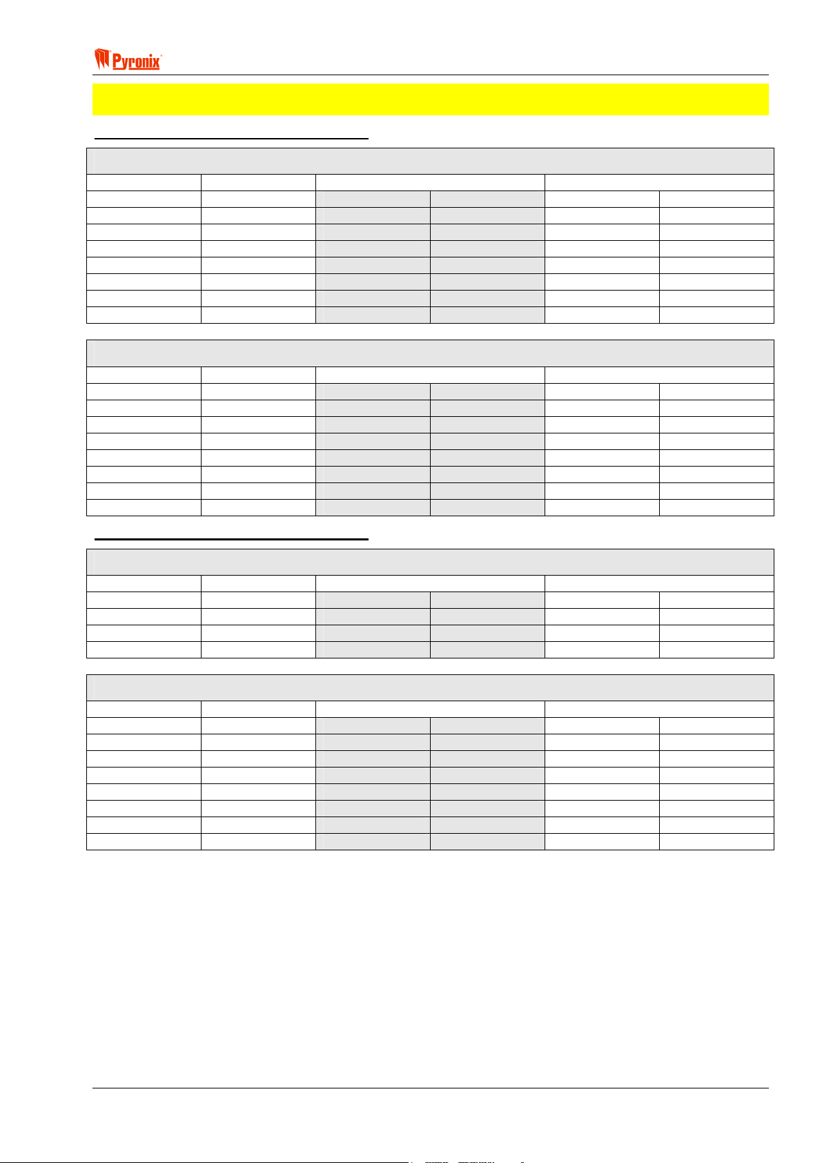
! Matrix 832 / 832+ / 424
NOTE: When zone doubling is enabled the matrix panel must be powered down and then powered up
before the change will take place. If zone doubling is used only one detector per zone may be used.
Table 1 – Zone Doubling with MATRIX 832
Zones Configuration on the Main PCB in N/C, DEOL and Zone Doubling Modes
Zone Inputs N/C Zones DEOL Zones Zone Doubling
Z1
Z2
Z3
Z4
Z5
Z6
Z7
Z8
Z1 – ALARM
Z2 – ALARM
Z3 – ALARM
Z4 – ALARM
Z5 – ALARM
Z6 – ALARM
Z7 – ALARM
Z8 – ALARM
Z1 – ALARM Z1 – TAMPER Z1 – ALARM Z17 – ALARM
Z2 – ALARM Z2 – TAMPER Z2 – ALARM Z18 – ALARM
Z3 – ALARM Z3 – TAMPER Z3 – ALARM Z19 – ALARM
Z4 – ALARM Z4 – TAMPER Z4 – ALARM Z20 – ALARM
Z5 – ALARM Z5 – TAMPER Z5 – ALARM Z21 – ALARM
Z6 – ALARM Z6 – TAMPER Z6 – ALARM Z22 – ALARM
Z7 – ALARM Z7 – TAMPER Z7 – ALARM Z23 – ALARM
Z8 – ALARM Z8 – TAMPER Z8 – ALARM Z24 – ALARM
Zones Configuration on the Zone Expander in N/C, DEOL and Zone Doubling Modes
Zone Inputs N/C Zones DEOL Zones Zone Doubling
Z9
Z10
Z11
Z12
Z13
Z14
Z15
Z16
Z9 – ALARM
Z10 – ALARM
Z11 – ALARM
Z12 – ALARM
Z13 – ALARM
Z14 – ALARM
Z15 – ALARM
Z16 – ALARM
Z9 – ALARM Z9 – TAMPER Z9 – ALARM Z25 – ALARM
Z10 – ALARM Z10 – TAMPER Z10 – ALARM Z26 – ALARM
Z11 – ALARM Z11 – TAMPER Z11 – ALARM Z27 – ALARM
Z12 – ALARM Z12 – TAMPER Z12 – ALARM Z28 – ALARM
Z13 – ALARM Z13 – TAMPER Z13 – ALARM Z29 – ALARM
Z14 – ALARM Z14 – TAMPER Z14 – ALARM Z30 – ALARM
Z15 – ALARM Z15 – TAMPER Z15 – ALARM Z31 – ALARM
Z16 – ALARM Z16 – TAMPER Z16 – ALARM Z32 – ALARM
Table 2 – Zone Doubling with MATRIX 424
Zones Configuration on the Main PCB in N/C, DEOL and Zone Doubling Modes
Zone Inputs N/C Zones DEOL Zones Zone Doubling
Z1
Z2
Z3
Z4
Z1 – ALARM
Z2 – ALARM
Z3 – ALARM
Z4 – ALARM
Z1 – ALARM Z1 – TAMPER Z1 – ALARM Z17 – ALARM
Z2 – ALARM Z2 – TAMPER Z2 – ALARM Z18 – ALARM
Z3 – ALARM Z3 – TAMPER Z3 – ALARM Z19 – ALARM
Z4 – ALARM Z4 – TAMPER Z4 – ALARM Z20 – ALARM
Zones Configuration on the Zone Expander in N/C, DEOL and Zone Doubling Modes
Zone Inputs N/C Zones DEOL Zones Zone Doubling
Z9
Z10
Z11
Z12
Z13
Z14
Z15
Z16
Z9 – ALARM
Z10 – ALARM
Z11 – ALARM
Z12 – ALARM
Z13 – ALARM
Z14 – ALARM
Z15 – ALARM
Z16 – ALARM
Z9 – ALARM Z9 – TAMPER Z9 – ALARM Z25 – ALARM
Z10 – ALARM Z10 – TAMPER Z10 – ALARM Z26 – ALARM
Z11 – ALARM Z11 – TAMPER Z11 – ALARM Z27 – ALARM
Z12 – ALARM Z12 – TAMPER Z12 – ALARM Z28 – ALARM
Z13 – ALARM Z13 – TAMPER Z13 – ALARM Z29 – ALARM
Z14 – ALARM Z14 – TAMPER Z14 – ALARM Z30 – ALARM
Z15 – ALARM Z15 – TAMPER Z15 – ALARM Z31 – ALARM
Z16 – ALARM Z16 – TAMPER Z16 – ALARM Z32 – ALARM
RINS428-5 Page 41

Matrix 832 / 832+ / 424
Arm Modes and Partitions
The system can be divided into up to 4 independent subsystems. One zone can be allocated to one
subsystem. Within each subsystem the zones can be operated in 4 different Arm Modes configurations A, B,
C and D.
Example
Partition 1 Partition 2 Partition 3 Partition 4
Arm A Arm A Arm A Arm A
Arm B Arm B Arm B Arm B
Arm C Arm C Arm C Arm C
Arm D Arm D Arm D Arm D
Arm A: Whole system armed, nobody on premises – Away
Arm B: Upstairs disarmed, downstairs armed – Home
Arm C: Upstairs armed, downstairs disarmed – Home
Arm D: Garage armed, the house disarmed – Home
NOTE: The engineer has the ability to configure the Matrix panel to the users exact requirement.
Zone Configuration Options Available
Display Type Description
o
l
w
rs
5
<
t
n
u
;
:
f
i
k
Entry / Exit
Access
Immediate
Medical
Zone
Arm Zone
Omitted
(Bypassed)
Fire
Personal
Attack
24-Hour
Zone
Keybox
Shunt
Keypad
Zone Type
Tamper
Latch
Keyswitch
Unused
This is a zone that allows limited-time access to the premises in order to arm or
disarm the system. This zone is typically connected to a magnetic door contact.
This is a zone which, on arming the panel, allows access to the Entry / Exit zone.
However, if the panel is armed and an Access zone is triggered before an Entry /
Exit zone then an alarm will be generated immediately.
This is a zone, which will, when activated, create an instant alarm when the panel is
armed.
The medical zone will send an emergency message to the central receiving station,
or emergency services.
The arm zone is used to end the exit time if the Arm option ‘Push to arm’ is enabled
- see section 8.11 Alarm Options. After the activation of this zone, the partition will
not arm until the expiry of the Final Exit Delay - see section 8.12 System Timers.
A zone programmed as an Omitted zone by the Engineer will be ignored by the
panel. It allows the user to continue to use the alarm system even if a fault has been
discovered on one or more zones.
Triggering the fire zone will always cause an alarm activation, regardless of whether
or not the panel is armed. A fire alarm is identified by a three note-ringing sound,
which is easily distinguished from all other tones. The external sounder will operate
at 1 second intervals.
Triggering the Personal Attack (P.A.) zone will always cause an alarm activation
regardless of whether or not the panel is armed. The P.A. zone may be
programmed as silent. A silent P.A. activation will not cause the bell or strobe to
operate, but the central station will be informed of a P.A. activation. One of the
programmable outputs will operate if the system has been programmed to do so.
Triggering a 24H zone will always cause an alarm activation regardless of whether
or not the panel is armed (Fire, Personal Attack and Tamper are all 24 hour zones).
This zone type is for connection to an external box, which when opened will cause
an activation of this zone, but will not cause an alarm. Activations of this zone are
logged and reported to the central monitoring station, using Contact ID 250.
This zone type is for connection to an external keypad with a pulsed output. During
the exit delay an activation of this zone causes the end of the exit time, a
programmable settling time (Final exit delay) is commenced before the panel fully
arms. An activation of this zone during armed mode causes the entry time to start.
Triggering the Tamper zone will always cause an alarm activation regardless of
whether or not the panel is armed. From system options, it may be programmed to
activate the internal siren only or internal and external sounder, in disarmed mode.
However in armed mode both sounders will operate.
It is possible by using this type of zone to arm / disarm the system in any arm mode
by using an external latched switch.
This zone is completely ignored by the system, however it is good practice to close
the zone by linking it with a 2K2 resistor.
Page 42 RINS428-5

! Matrix 832 / 832+ / 424
x
Arm Zones and DD243
If the option ‘Open set zone stops confirmation’ is on, this zone can be used to satisfy sections 6.3b
and 6.4.3 of DD243 when connected to a shunt lock. If the option ‘Open set zone stops confirmation’
is off, this zone can be used to satisfy section 6.3a of DD243.
Zone Attributes
Each zone can be allocated one of the following attributes. This will determine the zone operation for any of
the system modes of operation.
Chime - During an activation of any zone that has been allocated this attribute, the internal speaker/siren
(Twin Alert) and keypad sounder will emit a chime tone informing the occupant of a presence in that area.
Test - Any zone allocated this attribute will cause a zone activation during armed mode to be stored in the
memory log. However no alarm will be created and no communication report will be sent.
Test activations will be displayed to the user permanently by the word ‘TEST’ on an LCD RKP and the Alarm
light is illuminated on an LED RKP. This option will be removed from a zone if the zone has not had a valid
activation within 7 days. Each time the zone has a valid activation; the 7-day timer is reset. The 7-day timer
is started on exit from Engineer Mode.
Mask - If this attribute is allocated to a zone the system will not arm until the user walk-tests the zone. E.g.
enter the user code to arm the system, a low tone will be emitted from the keypad sounder (or internal
sounder/siren Twin Alert) and the arming timer countdown will not start until the zone is opened or closed at
least once.
This option can be used for high security installation purposes when particular zones can be exposed to the
public and there is a risk of masking detectors attached to them.
Double Knock - If this attribute is allocated to a zone the system will not acknowledge any activation until the
zone has been triggered twice within 5 minutes or it has been constantly activated for 10 seconds.
Normally Open / Normally Closed - If this attribute is allocated to a zone the system will sense activations
with opposite polarity, this option is useful for set zones where an ordinary bell push may be used.
Customer Map - This option allows you to draw or import up to 8 maps that show the general layout of a
premises. Keypads, proximity readers, detectors and user codes may also be added to the maps to show how
the complete system works as illustrated below:
Momentary
Keyswitch
It is possible by using this type of zone to arm / disarm the system in any arm mode
by using an external pulsed switch.
RINS428-5 Page 43
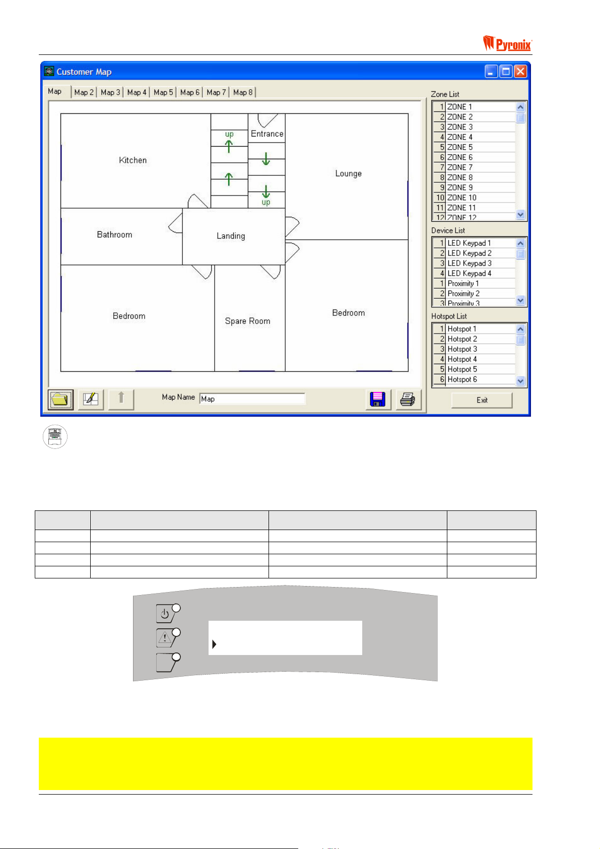
Matrix 832 / 832+ / 424
A
S
ARMED
ALARM
FAULT
SUPPLY
FIRE
8
8
P.A.READY
TAMPER
DAY
2134
BCD
ET
P.A.
5678
FIRE
FUNC
90
Keypad Programming Procedure
7.7.1 Zone Types
Enter BTW and use the > and ? buttons to select an option. To change an option, press the C button.
To save the changes press
B. An acceptance tone will be played.
Option Option Off = Alarm LED Off Option On = Alarm LED On Default
1 Double End of Line Zones Double Pole (N/C) Zones On
2 Zone Doubling disabled Zone Doubling enabled Off
3 350ms All Zones 100ms All Zones (Fast Zones) Off
4 Zone 1 30ms (fast) Zone disabled Zone 1 30ms (fast) Zone enabled Off
function 250
OPTION 1 on
OK
Display shows the indications, which are shown when entering zone types. Factory default for this option is
Double End of Line.
MATRIX
7.7.2 Zone Configuration
NOTE: The programming procedure for zones is as follows:
1 Programme the zone type for each of the 4 arm modes options
2 Programme the zone attribute for each of the 4 arm modes options
3 Choose a partition number to assign the zone and arm modes to.
Page 44 RINS428-5

! Matrix 832 / 832+ / 424
Enter BTW followed by zone number from [01 - 32].
The zone type for Arm A will then be displayed
Use
> or ? buttons to choose a zone type. Press B to accept and save the new zone type.
The zone type for Arm B will then be displayed
Use
> or ? buttons to choose a zone type. Press B to accept and save the new zone type.
The zone type for Arm C will then be displayed
> or ? buttons to choose a zone type. Press B to accept and save the new zone type.
Use
The zone type for Arm D will then be displayed
Use
> or ? buttons to choose a zone type. Press B to accept and save the new zone type.
The attributes for Arm A will now be displayed
To select an option use the
changes press
B. An acceptance tone will be played.
> and ? buttons. To change an option press the C button. To save the
Option Option Off = Alarm LED Off Option On = Alarm LED On Default
1 Chime Disabled Chime Enabled Off
2 Test Disabled Test Enabled Off
3 Mask Disabled Mask Enabled Off
4 Double Knock Disabled Double Knock Enabled Off
5 Normally Closed Normally Open Off
RINS428-5 Page 45

Matrix 832 / 832+ / 424
The attributes for Arm B will now be displayed
To select an option use the
changes press
B. An acceptance tone will be played.
> and ? buttons. To change an option press the C button. To save the
Option Option Off = Alarm LED Off Option On = Alarm LED On Default
1 Chime Disabled Chime Enabled Off
2 Test Disabled Test Enabled Off
3 Mask Disabled Mask Enabled Off
4 Double Knock Disabled Double Knock Enabled Off
5 Normally closed Normally Open Off
The attributes for Arm C will now be displayed
To select an option use the
changes press
B. An acceptance tone will be played.
> and ? buttons. To change an option press the C button. To save the
Option Option Off = Alarm LED Off Option On = Alarm LED On Default
1 Chime Disabled Chime Enabled Off
2 Test Disabled Test Enabled Off
3 Mask Disabled Mask Enabled Off
4 Double Knock Disabled Double Knock Enabled Off
5 Normally Open Normally Closed Off
The attributes for Arm D will now be displayed
To select an option use the
changes press
B. An acceptance tone will be played.
> and ? buttons. To change an option press C button. To save the
Option Option Off = Alarm LED Off Option On = Alarm LED On Default
1 Chime Disabled Chime Enabled Off
2 Test Disabled Test Enabled Off
3 Mask Disabled Mask Enabled Off
4 Double Knock Disabled Double Knock Enabled Off
5 Normally Open Normally Closed Off
The partition number allocated to this zone will then be displayed
Enter a partition number [1], [2], [3] or [4] to allocate the zone to. Press
allocation. An acceptance tone will be played.
The procedure will now return to the beginning to program the next zone. Repeat the above procedure for
each zone to be programmed.
Press
BB to exit this function.
B to save the partition
Page 46 RINS428-5

! Matrix 832 / 832+ / 424
Screens displayed through zone programming sequence:
function 251
MATRIX
Zone numbers: Enter the zone number [01 – 32] and press B to continue.
ARM MODE A
entry / exit
MATRIX
Zone configurations: Use the >? keys to scroll through zone types. Press B and repeat 4 times for part
sets A, B, C and D.
ARM MODE C
immediate
MATRIX
Zone attributes: Use the >? keys to change option number, and C key to change setting, then press B to
save and repeat 4 times for part sets A, B, C and D.
ARM MODE A
option 1 off
MATRIX
Allocating zones to partition No: Enter partition number [1 – 4] and press B to continue.
7.7.3 Zone Names Programming from LCD Keypad
BTWT
The following will be displayed.
SELECT ZONE 1 01
ZONE 1
MATRIX
Use the
The following will be displayed.
F and G keys to select the required zone and press B
EDIT TEXT 06
ZONE 6
MATRIX
Use the
D and E keys to scroll along the zone name and edit one character at a time.
Use the numerical number keys to edit the different letters for the zone name (see tables below).
Press
Press
B to accept the changes
@ to exit this option.
RINS428-5 Page 47

Matrix 832 / 832+ / 424
7.7.4 Key Map Tables
The following tables show how to obtain certain characters when programming user names, zone names etc.
Each time you press the same numerical key, the next character is chosen. There are three tables shown.
Use only the table that corresponds to the country of installation as some keys will vary.
Russian/Bulgarian
T U V W X Y Z [
A D G J M P S V Y A D G J M P S V Y
B E H K N Q T W Z 0 B E H K N Q T W Z 0
C F I L O R U X 9 # C F I L O R U X 9 #
1 2 3 4 5 6 7 8
À È
Á É
 Ê
à Ë
Ä Φ Ë Л Õ
Å
d
Æ З
Ç Ę Ç Ň
Б Б
Г Г
c
Ь Ь
Ы Ы
Ą Č
Ж
_
Э Ò Σ Ú У
`
И Ó π Û Ф Ш Â Ê
a
Й Ô Я Ü Ц Щ Ã Ë
b
Д Ь Ö Ś Ż Å
β Ù Π
/
Ъ Ч Ю Ä Φ Ë Л Õ
R
Ź Æ З Ř
]
! 1 2 3 4 5 6 7 8
ò
À È _ Ж
ó
Á É ` Э Ò Σ Ú У
Czech
T U V W X Y Z [
β Ù Π
/
И Ó π Û Ф Ш
a
Й Ô Я Ü Ц Щ
b
Ъ Ч Ю
R
Š Ś Ö ů Ž
d
c
ò
ó
ô
!
All Other Languages
T U V W X Y Z [
A D G J M P S V Y
B E H K N Q T W Z 0
C F I L O R U X 9 #
1 2 3 4 5 6 7 8
À È
Á É
 Ê
à Ë
Ä Φ Ë Л Õ
Å
d
Æ З Ń Ź
Ç Ę
Б
Г
c
Ь
Ы
Ą
Ж
_
Э Ò Σ Ú У
`
И Ó π Û Ф Ш
a
Й Ô Я Ü Ц Щ
b
Ć Ł Ö Ś Ż
β Ù Π
/
R
Ъ Ч Ю
ò
ó
!
Page 48 RINS428-5

! Matrix 832 / 832+ / 424
7.8 User Codes & User Attributes
PC Programming Procedure
The PC window below shows how to program user codes and names, engineer codes, engineer names and
user attributes from the PC software. Once you have chosen an option press <save> and proceed to the next
window.
NOTE: The system allows up to 32 user codes to be programmed as well as one engineer that must be
composed of 4,5 or 6 digits. Any of the user codes can be assigned to one or more partitions. Any of
the user codes can be allocated any of the user attributes.
Allocating Proximity Cards to User Code from PC
1. Connect the reader to the PC as shown in Section 7.2.1.
2. From the menu bar select <Tools>. Then select <Options>. Once in options window select <Comms>
tab. Now select the Proximity Reader PC communication port to be used (normally com 2). See section
11.5.1 for more information of setting up the communication port.
3. Select User Code number to assign the card to.
4. Press <Assign Card>. A window <Waiting To Read The Card> will be displayed for 15 seconds.
5. Present the card or tag to the reader. A window <Card Read Completed> or <Card Not Accepted> will be
displayed. The first will confirm the card programming. If the second is displayed then repeat the
procedure.
6. Once the cards read save the new data and disconnect the reader from the PC.
7. Reconnect the UDL software to the panel and upload the new data, - Now the panel will recognise the
newly programmed proximity cards and tags.
RINS428-5 Page 49

Matrix 832 / 832+ / 424
MEANING
Programmable Options Explanation
User Code Types
Limited user code - This code allows the user to arm / disarm the system, duress arming / disarming, omit
(bypass) zones if allowed by the engineer, Fire / PA / Medical keypad alarm activation, display open zones if
allowed by the engineer, silence fault tones, view event log, change volume, change brightness. The system
will treat any user code as a limited user if no master user attribute is allocated to this code.
Master user code - This attribute allocates master user functions to the user code. A master user will be
allowed to change any user code configuration within the same partition (e.g. if for partition 1 there are 4 user
codes allocated and user number one is master user then this code will be able to change any of the
remaining 3 user codes). The master user code allows all limited user functions plus programming of limited
user codes, changing time and date, pulse programming output, open 1H up / down loading window.
Editing User Code Attributes
User Code - Use this option to allocate a user code that can be min 4 up to 6 digits length.
User Name - Use this option to allocate a name to the user number.
User Allowed (0) Uses Of Code (Temporary / Cleaner / Patrol Code) - This option determines how many
times this code can be used to arm / disarm the system within one master or limited user code arm / disarm
period. It can be used for cleaner, maintenance or patrol purpose.
Example: Allocate 2 uses to the code if the code is used by a cleaner or patrol personnel:
Morning: In the morning the master or limited user arms the system with its own user code. Then the
cleaner or patrol will be able to once disarm the system and then once arm it again. More attempts will
not be accepted.
Evening: In the evening the master or limited user disarms the system with its own user code again.
Following the master or limited user code disarm, the temporary code can be re-used another 2 times.
This cycle repeats forever.
Master User - This option allocates master user functions to a user code. If a code is used as a master then
all user attributes should be allocated to this code.
Omit (Bypass) Zones - This attribute allows the user code to omit (bypass), zones.
Duress Code Only - It is possible to dedicate a separate duress code to be used from all users. When the
panel is armed / or disarmed using this code no visual alarm will be activated. However the digital
communicator will still send a transmission and the PGM programmed as Follow PA Alarm will be activated.
Duress code disabled - If enabled this attribute will permit the duress arming / disarming by reversing the
third & fourth digits of any of the user codes (e.g. if the user code is 123456 then the duress code will be
124356). This option will still be available if a separate duress code only is allocated.
Allow Arm - Allows the User code to arm the panel.
Allow Disarm - Allows the user code to disarm the panel.
Character Set Options
This is used for displaying and editing LCD keypad text for the matrix control panels, selecting the correct
character set on this window will allow the correct editing of this text on the matrix LCD screen. Failure to set
this correctly could result in incorrect data being sent to the panel.
The character set being used by default on the PC you are using is shown on the options screen.
You can select the default character set, which will use the character set the PC is using. Either ANSI
character set (world), CYR character set (Easten Europe) or CE character set (Central European)
See section 11.5.5 for full description of character set options.
NOTE: A standard user code must be allocated for either Allow Arm and Allow Disarm to work. These
options allow the engineer to dedicate codes for arming or disarming the system.
Page 50 RINS428-5

! Matrix 832 / 832+ / 424
User Code Active in Partitions
The selected user code may be active in partitions 1,2,3 or 4 by ticking the appropriate box.
NOTE: If one common keypad is used and different user codes are allocated to 4 separate partitions,
for instance partition 1 is allocated to flat 1, partition 2 is allocated to flat 2, partition 3 is allocated to
flat 3 and partition 4 is allocated to flat 4, then if user one from partition 1 chooses code 1234 and user
1 from partition 2 chooses the same code they will be able to arm / disarm both flats. To prevent this
from happening the engineer must allocate the first number of the user codes to each partition. For
instance all codes in partition 1 start with 1 followed by 5 numbers that the user chooses, all codes in
partition 2 start with 2 followed by 5 numbers that the user chooses, and so on.
If 4 keypads are used (one allocated to each partition) then if user codes are repeated they will arm /
disarm only the partition the keypad is allocated to.
Examples:
User Code Attributes Master User
User Code 123456 345678 444555 222345 987654
User Name John Anna Rosa Mavis Duress
Number of Uses Allowed 0 0 2 20 0
Master User Yes No No No No
Omit (Bypass) Zones Yes No No No No
Duress Code Only No No No No Yes
Duress Code Disabled Yes Yes Yes Yes No
Allow Arm Yes Yes No Yes No
Allow Disarm Yes Yes Yes No No
Active in partition 1 1 1 1 1
Limited
User
Temporary
User
Cleaner
Duress
Code
Proximity Card Information
To any of the 32 user codes it is possible to allocate a proximity card. This may be used with the MX-PROX
reader. The card or tag will behave exactly as the user code it is allocated to, is programmed to behave. It
may be used to arm / disarm the panel in different arm modes within one partition or partitions. It may be
master user card or limited user card. Cards can be allocated using the PC or manually through keypad user
functions.
No Card Programmed for User - This message informs the engineer if the chosen user code has or has not
been allocated to a proximity card. If this user has an allocated card then the tab will display <Card
Programmed for User>.
Card Clear - This button is used to clear a card that has been assigned to a chosen user code.
Assign Card - This button is used to assign a card to a chosen user code. The procedure for assigning cards
for user code is described in the PC programming part of this section.
RINS428-5 Page 51

Matrix 832 / 832+ / 424
A
S
ARMED
ALARM
FAULT
SUPPLY
FIRE
8
8
P.A.READY
TAMPER
DAY
2134
BCD
ET
P.A.
5678
FIRE
FUNC
90
Keypad Programming Procedure
7.8.1 Programming User Codes
The engineer should only program the user codes attributes. Codes should be allocated by the master user
only, following the procedures detailed in the user guide.
7.8.2 User Code Partition Allocation
Enter BU followed by the two digits for the user number [01 - 32]. To select an option use the > and
? buttons. To change an option press the C button. To save the changes press B. An acceptance tone will
be played.
Option Option Off = Alarm LED Off Option On = Alarm LED On Default
1 Not assigned to partition 1 Assigned to partition 1 On
2 Not assigned to partition 2 Assigned to partition 2 Off
3 Not assigned to partition 3 Assigned to partition 3 Off
4 Not assigned to partition 4 Assigned to partition 4 Off
7.8.3 User Code Attributes Allocation
Enter BU followed by the two digits of the user number [01 - 32]. To select an option use the > and
? buttons. To change an option press the C button. To save the changes press B. An acceptance tone will
be played.
Option Option Off = Alarm LED Off Option On = Alarm LED On Default
1 Omit (Bypass) Zones Disabled Omit (Bypass) Zones Enabled On
2 Normal User Code Duress Code Only Off
3 Duress Code Disabled Duress Code Enabled On
4 Disallow Arm Allow Arm On
5 Disallow Disarm Allow Disarm On
6 Spare Spare Off
7 Spare Spare Off
8 Limited User Code Master User Code 1=On, 2-32=Off
7.8.4 Temporary Code
NOTE: The number of uses of the temporary code can be defined as unlimited or any number from 1
to 99.
Enter
BUT followed by the two digits of the user code number from [01 - 32]. Enter the number of uses
for the code from [00] – [99]*. To save the changes press
B. An acceptance tone will be heard.
*[00] = Unlimited use of user code.
*[01] = Once only – after one use the code is deleted from memory.
*[02]…[99] = A number between 2-99 represents the amount of times the user code may be used – after the
programmed number of uses the code cannot be used again until an unlimited use code has been used at
least once.
7.8.5 Assigning / Clearing Proximity Card to / from User Code
The engineer should only program the user code attributes. Codes and proximity cards should be allocated by
the master user only, following the procedures from the user menu. See the user guide.
Page 52 RINS428-5

! Matrix 832 / 832+ / 424
7.9 Keypads & Proximity Readers Partition Allocation
PC Programming Procedure
The PC window below shows how to assign a keypad to a partition from the PC software. Once an option has
been chosen press the <save> button and proceed to the next window.
NOTE: Each keypad & proximity reader can be assigned to one or more partitions. In addition to this
the brightness and volume of each keypad may be adjusted. Before you start programming the Matrix
system it is important to allocate the keypads and proximity readers with the correct ID number, see
Sections 7.1 and 7.2.
MEANING
Programmable Options Explanation
Devices
LED Keypad 1 / LED Keypad 2 / LED Keypad 3 / LED Keypad 4 Each system can be allocated up to 4 LED
keypads that are identified by ID numbers 1, 2, 3 or 4. ID numbers are used to identify one keypad from
another and must be preset as indicated in Section 7.1. For each keypad it is possible to set different keypad
attributes as indicated in the paragraphs below.
Proximity Reader 1 / Proximity Reader 2 / Proximity Reader 3 / Proximity Reader 4 - Each system can be
allocated up to 4 Proximity Readers that are identified by ID numbers 1, 2, 3 or 4. These ID numbers are used
to identify one reader from another and must be preset as indicated in Section 7.2. For each reader it is
possible to set different reader attributes as indicated in the paragraphs below.
LCD Keypad 1 / LCD Keypad 2 / LCD Keypad 3 / LCD Keypad 4 - Each system can be allocated up to 4
LCD keypads that are identified by ID numbers 1, 2, 3 or 4. These ID numbers are used to identify one
keypad from another and must be preset as indicated in Section 7.1. For each keypad it is possible to set
different keypad attributes as indicated in the paragraphs below.
Day Message
This message can be programmed by the installer to display text appearing on the LCD display while the
control panel is in disarmed mode. It is possible to choose a message to be displayed from “LCD Keypad Text
1”. This can be a message such as DISARMED, SERVICE TEL NUMBER, COMPANY NAME and so on.
RINS428-5 Page 53

Matrix 832 / 832+ / 424
Armed Message
This message can be programmed by the installer to display text on the LCD display while the control panel is
in armed mode, and the keypad is configured as a private keypad. It is possible to choose a message to be
displayed from “LCD Keypad Text 1”. This can be a message such as ARMED, SERVICE TEL NUMBER,
COMPANY NAME and so on.
RKP Controlled Output Text
This message can be programmed by the installer to display text in connection with the available user option
to activate a PGM output from the keypad. This can be message such as OPEN DOOR, RESET
DETECTORS, ACTIVATE LIGHTS and so on.
Language Number
Number 000 is English. To allocate other languages available with this LCD version choose a language from
the language list. It is the responsibility of the Installer to make sure that the chosen language is available in
that version of keypad.
LCD Keypad Text 1
There are 26 text labels available, the text of which can be freely programmed and displayed on any of the 4
LCD keypads used by the system.
LCD Keypad Text 2
This option contains text labels that can be displayed on Engineer Mode entry.
LCD Keypads & Proximity Readers
Active in Partition
This enables keypads/proximity readers 1, 2, 3 and 4 to be allocated to different partitions. It is possible to
allocate keypads/proximity readers to 1 or more partitions. If allocated to one partition the keypad / reader will
operate and display system information only within this partition.
Private/Public
This option enables the visual information on a keypad to be programmed as private or public. If private the
system status will only be shown while the panel is being armed. If public then the system status will be
shown in any state of the panel.
Brightness
This option allows the brightness of individual keypads to be adjusted to different levels. By sliding the
brightness handle on the PC screen to the left the brightness will decrease. By sliding the brightness handle
on the PC screen to the right the brightness will increase.
Volume
This option allows the volume of individual keypads to be adjusted to different levels. By sliding the volume
handle on the PC screen to the left the volume will decrease. By sliding the volume handle on the PC screen
to the right the volume will increase.
Contrast
This option allows the LCD keypad display contrast to be adjusted. The Factory default is adequate for most
situations. Installations in warmer or cooler environments may require this setting to be adjusted for optimum
readability.
NOTE: The LCD contrast can be adjusted such that it is unreadable, care must be taken so this does
not occur.
NOTE: See user guide for the procedure to adjust brightness and volume from the keypad.
Page 54 RINS428-5
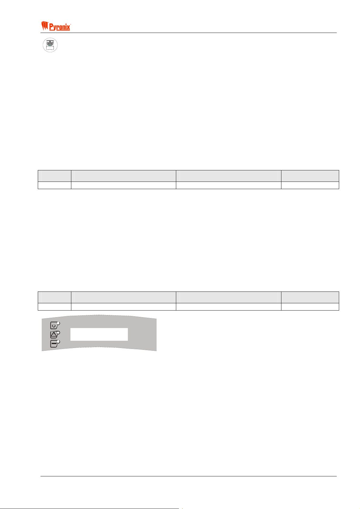
! Matrix 832 / 832+ / 424
A
S
ARMED
ALARM
FAULT
SUPPLY
FIRE
8
8
P.A.READY
TAMPER
DAY
2134
BCD
ET
P.A.
5678
FIRE
FUNC
90
Keypad Programming Procedure
7.9.1 Icon Keypad Programming
7.9.1.3 Icon Keypad Partition Allocation
Enter BUW followed by one digit to choose keypad ID number from [1 - 4]. The current setting will be
displayed. Press [1 - 4] to assign a partition to the keypad. To save the changes press
B. An acceptance
tone will be played.
The option will repeat from the beginning.
Press
BB to exit the programming.
7.9.1.4 Icon Keypad Private / Public Mode
BUW followed by one digit for the desired keypad ID number [1 - 4]. To select an option use the > and
? buttons. To change an option, press the C button. To save the changes press B. An acceptance tone
will be played.
Option Option Off = Alarm Icon Off Option On = Alarm Icon On Default
1 Keypad Public enabled Keypad Private enabled Off
7.9.2 LCD Keypad Programming
7.9.2.1 LCD Keypad Partition Allocation
Enter BUWT followed by one digit to select the keypad ID number from [1 - 4]. The current keypad
partition allocation will be shown. Press [1 - 4] to assign partitions to the keypad. To save the changes press
B. An acceptance tone will be played.
The function will repeat from the beginning. Press
BB to exit the programming.
7.9.2.2 LCD Keypad Private / Public Mode
Enter BUWU followed by one digit for the desired keypad ID number [1 - 4]. To select an option use the
> and ? buttons. To change an option, press the C button. To save the changes press B. An acceptance
tone will be played.
Option Option Off = Alarm Icon Off Option On = Alarm Icon On Default
1 Keypad Public enabled Keypad Private enabled Off
function 3 53
option 1 off
MATRIX
The display shows the indications that are shown on entering private/ public mode.
RINS428-5 Page 55

Matrix 832 / 832+ / 424
7.9.2.3 Change Label Messages on LCD keypad
NOTE: This option allows the engineer to edit and change the text on all available label messages.
There are 32 (01 – 32) different labels that can be selected. The engineer can edit any of these labels.
Enter
BUWV. The following display will be shown.
SELECT LABEL 01
DISARMED
MATRIX
Use the F and G keys to choose the required label and enter B to select it. The following display will
now be shown.
EDIT TEXT 01
DISARMED
MATRIX
Use the F and G keys to scroll the flashing key along the label text to edit. Use the numerical number
keys on the keypad to change the text. Press
keymap table on page 48 for details on how to obtain all of the available alphanumeric characters.
B to accept the changes. Press @ to exit this option. See the
LCD RKP – Editable Label Text and Allocation Table
Keypad Label No. Default Text Allocation
LCD (ID1) 1 DISARMED LCD Keypad (ID1) Day message
LCD (ID2) 2 DISARMED LCD Keypad (ID2) Day message
LCD (ID3) 3 DISARMED LCD Keypad (ID3) Day message
LCD (ID4) 4 DISARMED LCD Keypad (ID4) Day message
LCD (ID1) 5 ARMED LCD Keypad (ID1) Armed message
LCD (ID2) 6 ARMED LCD Keypad (ID2) Armed message
LCD (ID3) 7 ARMED LCD Keypad (ID3) Armed message
LCD (ID4) 8 ARMED LCD Keypad (ID4) Armed message
None 9 LABEL Spare
None 10 LABEL Spare
None 11 LABEL Spare
None 12 LABEL Spare
None 13 LABEL Spare
None 14 LABEL Spare
None 15 LABEL Spare
None 16 LABEL Spare
None 17 LABEL Spare
None 18 LABEL Spare
None 19 LABEL Spare
None 20 LABEL Spare
None 21 LABEL Spare
None 22 LABEL Spare
None 23 LABEL Spare
None 24 LABEL Spare
None 25 LABEL Spare
None 26 LABEL Spare
LCD (ID1) 27 PULSE PGM 1 LCD Keypad (ID1) Pulse PGM message
LCD (ID2) 28 PULSE PGM 2 LCD Keypad (ID2) Pulse PGM message
LCD (ID3) 29 PULSE PGM 3 LCD Keypad (ID3) Pulse PGM message
LCD (ID4) 30 PULSE PGM 4 LCD Keypad (ID4) Pulse PGM message
LCD (ID1-ID4) 31 WELCOME Top line Engineer Mode entry message
LCD (ID1-ID4) 32 ENGINEER Bottom line Engineer Mode entry message
Page 56 RINS428-5
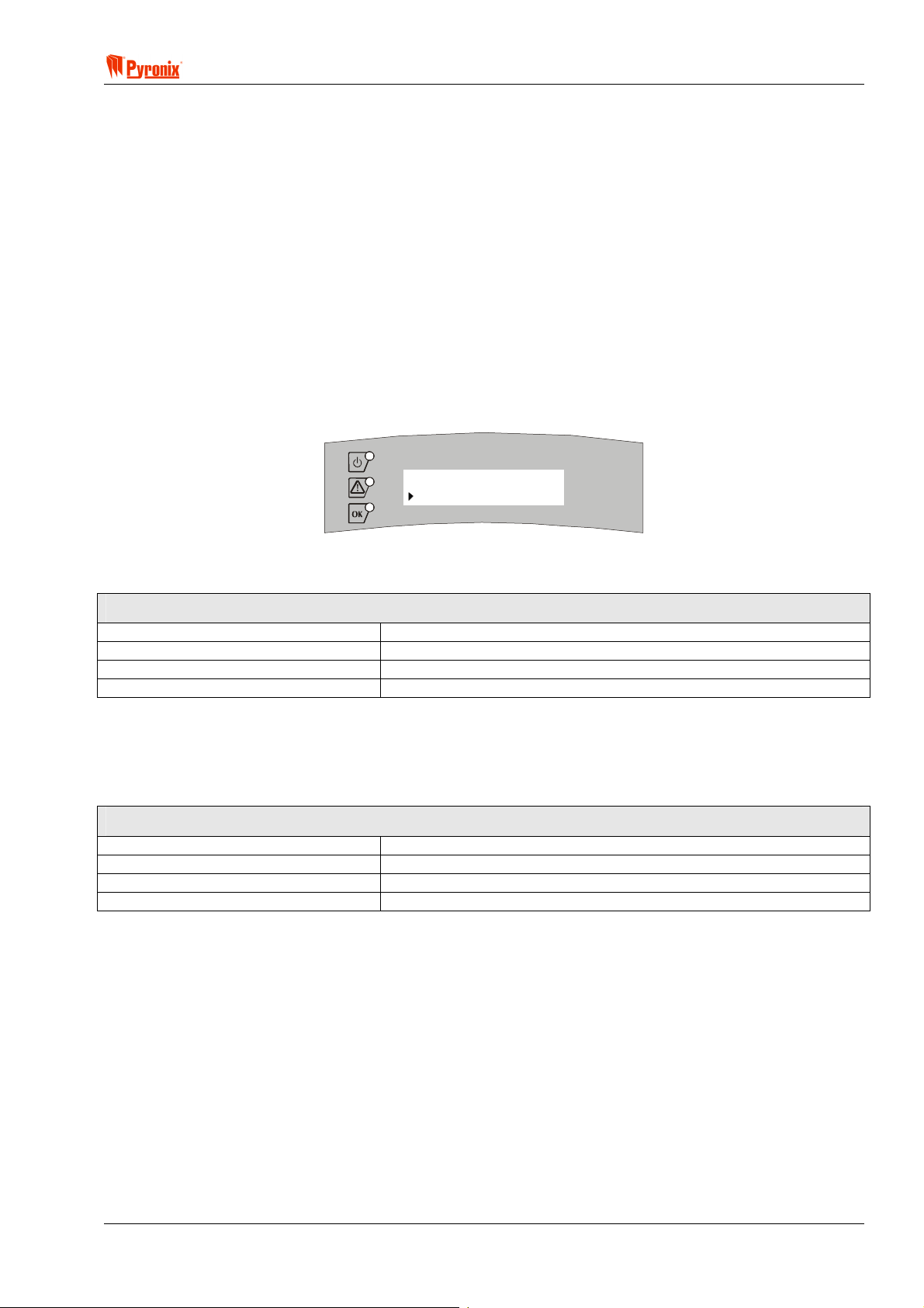
! Matrix 832 / 832+ / 424
The default Day message is displayed when the panel is disarmed in day mode. It is displayed on the bottom
line of the LCD display.
The default Armed message is displayed when the panel is Armed and has been programmed for private
mode. It is displayed on the bottom line of the LCD display.
The PULSE PGM message is displayed as a user menu item. If the programmable output is connected to (for
example) a fire detector reset input, then you might change this message to RESET FIRE DET.
The welcome engineer message is displayed every time Engineer Mode is entered. This message might be
changed (for example), to inform the engineer where the alarm panel is installed.
All of the spare messages can be populated with any message you want. To display the message you need to
re-map the default armed or disarmed message to the new message number. The reason that there are a lot
of spare messages is so that an engineer can populate them with common disarmed and armed mode
messages and can select which one is appropriate for each installation.
7.9.2.4 Allocating a Label to a Keypad to be Displayed when Disarmed
Enter BUWW followed by a keypad ID [1 - 4] of the keypad to assign the disarmed message to. The
following display will be shown.
DAY LABEL 01
DISARMED
MATRIX
Use the
acceptance tone will be played.
F and G keys to select the required label number [1 – 26]. Press B to confirm. An
Factory default Settings for Message Displayed in Disarmed Mode
Disarmed LCD Keypad 1
Disarmed LCD Keypad 2
Disarmed LCD Keypad 3
Disarmed LCD Keypad 4
7.9.2.5 Allocating a Label to a Keypad to be Displayed when Armed
Enter BUWX followed by the keypad ID [1 - 4] of the keypad to assign the armed message to. Use the
F and G keys to select the required label number [1 – 26]. Press B to confirm. An acceptance tone
will be played.
Factory default Settings for Message Displayed in Armed Mode
Disarmed LCD Keypad 1
Disarmed LCD Keypad 2
Disarmed LCD Keypad 3
Disarmed LCD Keypad 4
RINS428-5 Page 57

Matrix 832 / 832+ / 424
7.9.2.6 Setting the Contrast of the LCD Display
Enter BUWY. The following display will be shown.
Adjust contrast
Use up - down keys
MATRIX
The F key reduces the contrast
The
G key increases the contrast
Press
B to accept the new contrast setting.
The LCD contrast controls the darkness of the characters shown on the LCD display.
By default the contrast is set to an optimum setting and will not automatically need to be changed. Care must
be exercised when changing the contrast so as not to loose the display completely.
7.9.3 Proximity Reader Programming
7.9.3.1 Proximity Reader Partition Allocation
Enter BUWZ followed by 1 digit to choose proximity reader ID number from [1 - 4]. The current setting will
be displayed. Press [1 - 4] to assign partitions to the reader. To save the changes press
tone will be played.
B, an acceptance
The function will repeat from the beginning. Press
programming.
BB to exit proximity reader partition allocation
7.9.3.2 Proximity Reader Private / Public Mode
Enter BUW[ followed by the one digit for the desired proximity reader ID number [1 - 4]. To select an
option number use
To save the changes press
> and ? buttons. To change an option setting press the C button.
B. An acceptance tone will be played.
Option Option Off = Alarm LED Off Option On = Alarm LED On Default
1 Proximity Reader Public Enabled Proximity Reader Private Enabled Off
7.9.4 Changing Default Language on LCD Keypad
Enter BUX. The following display will be shown.
KEYPAD
_ [ 1 to 4 ]
MATRIX
Enter the keypad number [1 - 4] for the keypad you wish to change the language of. The following display will
be shown.
SELECT LANGUAGE
ENGLISH
MATRIX
Use the F or G keys to select a language. Press B to accept the language. The function will
automatically exit.
Note: The language change will take effect only after leaving Engineer Mode.
Page 58 RINS428-5

! Matrix 832 / 832+ / 424
A
S
7.10 System Faults & Tamper Alarms Warning Allocation
PC Programming Procedure
The PC window below shows how to assign system faults and tamper alarms to a partition from the PC
software. Once an option has been chosen, press <save> and proceed to the next window.
MEANING
Programmable Options Explanation
Active in Partition
System faults Notification Partition Allocation
This option allows the engineer to program which partitions in the system will be able to display system faults.
“0” stands for disable.
Bell and Tamper Faults Partition Notification
This option allows the engineer to program which partitions in the system will be able to display bell and
tamper faults. “0” stands for disable.
ARMED
ALARM
FAULT
SUPPLY
FIRE
8
8
P.A.READY
TAMPER
DAY
2134
BCD
ET
P.A.
5678
FIRE
FUNC
90
Keypad Programming Procedure
7.10.1 System Faults (Warning Partition Allocation)
Enter BUZ. The current setting will be displayed. Enter partition numbers [0]* or [1 - 4]. To allocate
system faults notification to. To save the changes press
B. An acceptance tone will be heard.
*[0] = 0 as the first partition will cause system faults to display in all partitions.
7.10.2 Bell And Tamper Faults (Warning Partition Allocation)
Enter BUZ. The current setting will be displayed. Enter partition numbers ([0]* or [1 - 4]) to allocate
tamper notification to. To save the changes press
B. An acceptance tone will be heard.
*[0] = 0 as the first partition will cause system faults to display in all partitions.
RINS428-5 Page 59

Matrix 832 / 832+ / 424
7.11 Partition Options
PC Programming Procedure
The PC window below shows partition options 1 and 2 for partition 1 of the PC software. On the left hand side
of this screen shot is a partition selection box, which should be used to change between desired partitions. 1,
2, 3 and 4.
Information in one partition can be copied into other partitions by selecting a partition number in the partition
selection box and clicking the “>>” button. Once all desired options have been chosen, press <save> and
proceed to the next window.
MEANING
Programmable Options Explanation
Partition Options 1
PA Alarm
Silent - If the Personal Attack zone is activated in silent mode the internal or external sounders will not sound.
Dial out will occur if the panel has been programmed to do so.
Audible - The Personal Attack zone activation will cause both internal and external sounders to operate. Dial
out will also occur if the panel has been programmed to do so.
Spare
Not used (options may be added in future development).
Tamper Alarm
Internal And External - This option will cause both internal (keypad sounders) and external sounders to
activate on a tamper alarm when the panel is in disarmed mode.
Internal Only - This option will cause only the internal (keypad sounders) sounder to activate upon a tamper
alarm when the panel is in disarmed mode. In armed mode both sounders will always operate
Page 60 RINS428-5

! Matrix 832 / 832+ / 424
Display Open Zones When Disarmed
Yes - When the panel is in disarmed mode, any open zones will be displayed on the keypad. To arm the
system all zones should be closed. If all zones are closed the ready LED will be activated on the keypad and
only then the system should be armed. If there are zones open the highest zone number will be displayed on
the keypad. To view the open zone numbers use the > and ? keys.
No - When the panel is in disarmed mode these zones are not displayed on the keypad, although the > and
? keys will still work.
Omit (Bypass) Zones on Rearm
Yes - After the end of the alarm time the system will automatically arm again and any zone that is still open
will be omitted for this arming period. The zone will not cause any subsequent alarms. However this event will
be entered into the memory log and an omit event will be transmitted to the CMS.
No - After the end of the alarm time the system will automatically arm again and any zone that is still open will
be ignored. Any ignored zone can cause an alarm if closed and then opened.
Bell Squawk
Yes - When the system arms the bell output will be activated for 1 sec when armed and for 2 pulses per 1 sec
when disarmed. This option will provide the user with outdoor (from the external sounder) audible confirmation
of arming / disarming the system.
No - Upon arming the system the bell output will not be activated.
Kiss off Confirmation Tone
Yes - After completing a successful event transmission to the Central monitoring station, the keypad sounder
and internal sounder (Twin Alert) will emit a confirmation tone for successful transmission.
No - After completing the transmission no confirmation tone will be emitted from the keypad and the internal
sounder.
Display Open Zones in Alarm
Yes - When the panel is in armed mode the last activated zone will be displayed on the keypad. To view the
zone numbers for the zones that have been open during this alarm period use the > and > keys. The LCD
keypad will display the zone names. When a zone is still open, the LCD RKP displays a ‘!’ symbol next to the
zone name.
No - When the panel is in armed mode these zones are not displayed on the keypad.
Partition Options 2
Bell Time
Seconds - The bell time is normally programmed in minutes. However it is also possible to program the bell
time in seconds.
Minutes - The bell time will be programmable in minutes.
Anti-Code Reset
Yes - Entering a user code will only silence alarm activations. To reset the system a unique anti-code must
be entered into an RKP, after which, full functionality of the system is restored. A random ‘seed’ code is
generated by the Panel, which is displayed on the RKP by pressing the C button. The ‘seed’ must be given to
the Central Station or Installer. The Central Station or Installer generates the unique anti-code by the using
special software to generate the anti-code.
No - User codes can reset the system.
Engineer Reset
Yes - Entering a user code can silence alarm activations. To reset the system an Engineer code must be
entered into an RKP
No - User codes can reset the system.
Engineer / Anti Code Reset
All - All alarms are required to be reset by one of the two methods above.
Confirmed Alarms - Only confirmed alarms need to be reset by one of the two methods above.
Note - Both Engineer and Anti-code reset can be enabled and either code will reset the system.
RINS428-5 Page 61

Matrix 832 / 832+ / 424
A
S
External Sounder
Normal Operation - The sounders will operate using the standard bell time and re-arm settings.
French Operation - The resulting bell output (type 14) operation is as follows:
The Bell time is fixed to 3 minutes (or seconds if bell time in seconds is selected).
No more than 4 bell activations are allowed per arm period.
The resulting Internal Keypad sounder operation is:
If all zones are closed at the end of the Bell time, the internal sounders stop.
If any zone is open at the end of the Bell time, the sounders continue until the zone is closed or the
panel is disarmed.
Bell Restore Log Event:
The Bell restoral log event (r2) is logged whenever a sounder stops. I.e., if the bell has activated 4
times the restoral will be logged each time the bell times out, or after 4 activations the restoral will be
logged when the internal sounders time out and all zones are closed.
Re-arms
The re-arms feature interferes with the French Sounder operation, therefore when the French Sounder
is enabled the re-arms feature is disabled.
Internal Sounder Programmable Output Type
Any of the 4 outputs can be programmed to be an internal sounder. This sounder will follow the
operation of the keypad alarm tones.
The number for Internal Sounder is type 16.
Zone Restorals
Allow After Disarm – Allows the transmission and logging of zone restorals via the on-board digital
communicator, but only after disarm if the zone has previously caused an alarm transmission.
Do Not Allow After Disarm – Does not allow the transmission and logging of zone restorals via the on-board
digital communicator, but only after disarm if the zone has previously caused an alarm transmission.
ARMED
ALARM
FAULT
SUPPLY
FIRE
8
8
P.A.READY
TAMPER
DAY
2134
BCD
ET
P.A.
5678
FIRE
FUNC
90
Keypad Programming Procedure
7.11.1 Partition Options 1
Enter BV followed by one digit for the desired partition number [1 - 4]. To choose an option use the
> and ? buttons. To change an option setting, press the C button. To save the changes press B. An
acceptance tone will be played.
Option Option Off = Alarm LED Off Option On = Alarm LED On Default
1 PA Alarm Audible PA Alarm Silent Off
2 SPARE SPARE Off
3 Internal Sirens on Tamper Alarm Internal And External sirens on Tamper
Alarm
4 Display Open Zones In Disarmed Mode
Disabled
Display Open Zones In Disarmed Mode
Enabled
5 Omit (Bypass) Zones on Rearm Disabled Omit (Bypass) Zones on Rearm Enabled On
6 Bell Squawk Off Bell Squawk On Off
7 Kiss-off Confirmation Tone Off Kiss-off Confirmation Tone On Off
8 Display Open Zones in Alarm Disabled Display Open Zones in Alarm Enabled On
On
On
Page 62 RINS428-5
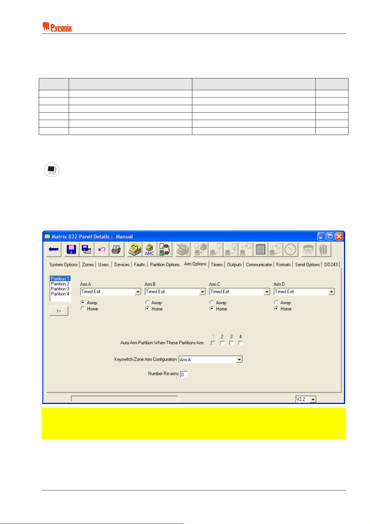
! Matrix 832 / 832+ / 424
7.11.2 Partition Options 2
Enter BV followed by one digit for the desired partition number [1 - 4]. To choose an option use the
> and ? buttons. To change an option setting, press the C button. To save the changes press B. An
acceptance tone will be played.
Option Option Off = Alarm LED Off Option On = Alarm LED On Default
1 Bell Time is Minutes Bell Time is Seconds Off
2 Anti-code Reset Disabled Anti-code Reset is Enabled Off
3 Engineer Reset is Disabled Engineer Reset is Enabled Off
4 Reset Required after Confirmed Alarms Reset Required after All Alarms Off
5 Normal Sounder Operation French Sounder Operation Off
6 Do not allow zone restorals after disarm Allow zone restorals after disarm Off
7.12 Arm Options
PC Programming Procedure
The PC window below shows arm options on the PC software. On the left hand side of this screen shot is a
partition selection box, which should be used to change between desired partitions. 1, 2, 3 and 4.
Information in 1 partition can be copied into other partitions by selecting a partition number in the partition
selection box and pressing the “>>” button.
Once all desired attributes have been chosen press <save> and proceed to the next window.
NOTE: There are 5 different exit terminator types for the arm modes A, B, C and D. Each of these arm
modes can be programmed in either Home or Away mode.
Home and Away allocation will also enable programming of partition dependency if more than one
partition is selected.
RINS428-5 Page 63

Matrix 832 / 832+ / 424
MEANING
Programmable Options Explanation
Arm Modes
There are 4 arm modes that can be programmed to arm different zones within one partition area.
Example
Partition 1 Partition 2 Partition 3 Partition 4
Arm A Arm A Arm A Arm A
Arm B Arm B Arm B Arm B
Arm C Arm C Arm C Arm C
Arm D Arm D Arm D Arm D
Arm A: Whole system armed, no body on premises – Away
Arm B: Upstairs disarmed, downstairs armed – Home
Arm C: Upstairs armed, downstairs disarmed – Home
Arm D: Garage armed, the house disarmed – Home
Arm Mode Attributes
Timed Exit – To arm the system the user needs to enter his code from the keypad. This will activate the
countdown of entry / exit time (see Section 7.12.4 on System Timers to program the entry / exit time). At the
end of this time the panel will arm.
Final Exit – To arm the system the user needs to enter their code from the keypad. This will activate the
countdown of entry / exit time (see Section 7.12.5 on System Timers to program the entry / exit time).
However the system will not arm until the last zone is closed (it is recommended several seconds delay is
programmed for the final zone sense, see Timers).
Silent Arm – During the exit time the keypad sounder will normally audibly inform the user at the beginning of
the countdown. This option will turn off the keypad sounder during the exit time. This option is typically used
for arming the system during the night.
Push to Arm – To arm the system the user needs to enter his code from the keypad. This will activate the
countdown of entry / exit time (see Section 8.12.3 / 8.12.4 on System Timers to program the entry / exit
time). However the system will not arm until a Set zone is activated (it is recommended several seconds delay
are programmed for the Final Exit delay to allow any detectors on the exit route to settle – see section 8.12.5
Final Exit Delay).
Forced Arm –This option is identical in operation to timed exit, with the addition that when the exit time
expires any open zones are omitted until they finally close, when they will then be fully monitored.
Keyswitch Arm Configuration
This option allows the engineer to program which arm mode the zone programmed as a keyswitch will arm in.
This option can be used with an external keyswitch arming/disarming module via radio etc.
Arm Mode Types
Home - this option is used when the system is armed in one of the arming modes but the users are still in the
premises (for instance first floor armed but the second not), such as arm mode B discussed in an earlier
example.
Away - this set option is used when the system is fully armed and no one is on the premises for example
when all zones are armed, such as arm mode A as discussed in an earlier example.
Page 64 RINS428-5
! Matrix 832 / 832+ / 424
A
S
Common Partition Programming
Auto Arm Partition When These Partitions Arm (Partition Dependency)
In some instances there is a need to program one or more partitions as common partitions. For instance if we
use partition 2, 3 and 4 to protect 3 separate flats we might need to use partition 1 as a common partition
protecting the lobby area. In order to achieve this we need to program the following options:
1. Allocate user code 2 to partition 1+2, allocate user code 3 to partition 1+3, allocate user code 4 to
partition 1+4.
2. Program the partition dependency option so that partition 1 arms when partition 2, 3 and 4 are armed in
away mode.
3. If 3 keypads are used – one in each flat - allocate keypad 2 to partition 1+2, Allocate keypad 3 to partition
1+3, allocate keypad 4 to partition 1+4.
Arming Partition
To arm for instance partition 2 enter user code number 2, then select partition 2 from the keypad and
press FUNC to confirm the procedure. The partition will start arming. When partition 2+3+4 are armed
in away mode partition 1 that is common will arm automatically.
Disarming Partition
To disarm for instance partition 2 enter your user code 2, them disarm partition 2, to disarm partition 3
enter user code 3 and disarm partition 3, to disarm partition 4 enter user code 4 and disarm partition 4.
When partition 2,3 or 4 disarm, the common partition (1) will disarm automatically
Number of Re-arms
Number of times the partition will re-arm automatically after the bell timer expires. “0” stands for
continuous arming after alarm.
ARMED
ALARM
FAULT
SUPPLY
FIRE
8
8
P.A.READY
TAMPER
DAY
2134
BCD
ET
P.A.
5678
FIRE
FUNC
90
Keypad Programming Procedure
7.12.1 Exit Terminator Type for Arm Mode A
Enter BVW followed by one digit for the desired partition number [1 - 4]. The current Arm type will be
displayed. To select the type of arm mode enter [00], [01] or [02]. To save the changes press
acceptance tone will be played.
Default
Arm Mode Description
Partition 1 Partition 2 Partition 3 Partition 4
00 Timed Exit On On On On
01 Final Exit Off Off Off Off
02 Silent Arm Off Off Off Off
03 Push to Arm Off Off Off Off
04 Forced Arm Off Off Off Off
B. An
7.12.2 Exit Terminator Type for Arm Mode B
Enter BVW followed by one digit for the desired partition number [1 - 4]. The current Arm type will be
displayed. To select the type of arm mode enter [00], [01] or [02]. To save the changes press
acceptance tone will be played.
Default
Arm Mode Description
Partition 1 Partition 2 Partition 3 Partition 4
00 Timed Exit On On On On
01 Final Exit Off Off Off Off
02 Silent Arm Off Off Off Off
03 Push to Arm Off Off Off Off
04 Forced Arm Off Off Off Off
RINS428-5 Page 65
B. An

Matrix 832 / 832+ / 424
7.12.3 Exit Terminator Type for Arm Mode C
Enter BVWT followed by one digit for the desired partition number [1 - 4]. The current Arm type will be
displayed. To select the type of arm mode enter [00], [01] or [02]. To save the changes press
acceptance tone will be played.
B. An
Arm Mode Description
Default
Partition 1 Partition 2 Partition 3 Partition 4
00 Timed Exit On On On On
01 Final Exit Off Off Off Off
02 Silent Arm Off Off Off Off
03 Push to Arm Off Off Off Off
04 Forced Arm Off Off Off Off
7.12.4 Exit Terminator Type for Arm Mode D
Enter BVWU followed by one digit for the desired partition number [1 - 4]. The current Arm type will be
displayed. To select the type of arm mode enter [00], [01] or [02]. To save the changes press
acceptance tone will be played.
B. An
Default
Arm Mode Description
Partition 1 Partition 2 Partition 3 Partition 4
00 Timed Exit On On On On
01 Final Exit Off Off Off Off
02 Silent Arm Off Off Off Off
03 Push to Arm Off Off Off Off
04 Forced Arm Off Off Off Off
7.12.5 Home & Away Allocation
Enter BVWV followed by one digit for the desired partition number [1 - 4]. To choose an option use the >
? buttons. To change an option setting, press the C button. To save the changes press B. An
and
acceptance tone will be played.
Option Arm Mode Option Off = Alarm LED Off Option On = Alarm LED On Default
1 A Home Away On
2 B Home Away Off
3 C Home Away Off
4 D Home Away Off
7.12.6 Partition Dependency
Enter BVWW followed one digit for the desired partition number from [1 - 4]. To choose an option use the
> and ? buttons. To change an option setting, press the C button. To save the changes press B. An
acceptance tone will be played.
Option Option Off = Alarm LED Off Option On = Alarm LED On Default
1 Partition will Not Arm with Partition 1 Partition will Arm with Partition 1 Off
2 Partition will Not Arm with Partition 2 Partition will Arm with Partition 2 Off
3 Partition will Not Arm with Partition 3 Partition will Arm with Partition 3 Off
4 Partition will Not Arm with Partition 4 Partition will Arm with Partition 4 Off
Page 66 RINS428-5

! Matrix 832 / 832+ / 424
7.12.7 Keyswitch Zone Arm Mode Allocation
Enter BVWX followed by one digit for the desired partition number from [1 - 4]. The current Arm mode
will be displayed. To choose an option, enter [01]…[04]. To save the changes press
will be heard.
B. An acceptance tone
Option Description
Default
Partition 1 Partition 2 Partition 3 Partition 4
01 Arm Mode A On On On On
02 Arm Mode B Off Off Off Off
03 Arm Mode C Off Off Off Off
04 Arm Mode D Off Off Off Off
7.12.8 Number of Rearms
Enter BVWY followed by one digit for the desired partition number from [1 - 4]. The current number of
rearms will be displayed. To select the number of auto-arms press [0]*…[9]*. To save the changes press
An acceptance tone will be heard.
*[0] - continuous auto-arm.
*[1]…[9] – fixed number of auto-arms from 1 to 9 times.
B.
RINS428-5 Page 67
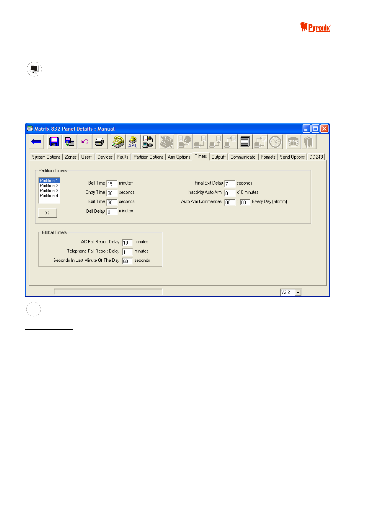
Matrix 832 / 832+ / 424
7.13 System Timers
PC Programming Procedure
The PC window below shows how to program the system times from the PC software. On the left hand side of
this screen shot is a partition selection box, which should be used to change between desired partitions. 1, 2,
3 and 4. Information in 1 partition can be copied in to other partitions by selecting a partition number in the
partition selection box and pressing the “>>” button. Once all desired attributes have been chosen press
<save> and proceed to the next window.
MEANING
Programmable Options Explanation
Partition Timers
Bell Time - This is the duration of the alarm. It can be set from 2 to 20 minutes or seconds (this depends on
the setting in Partition Options 2, Section 8.10.2).
Entry Time - This is the countdown time that allows the user to enter the premises and disarm the system. It
can be set from 2 to 99 seconds.
Exit Time - This is the countdown time that allows the user to exit the premises before the system arms. It
can be set from 2 to 99 seconds.
Bell Delay - This is a siren activation delay time that can be set from 0 to 99 minutes. However the event will
be reported independently of the bell delay setting.
Final Exit Delay - This is time delay for the last zone to close and can be set from 0 to 99 seconds. This must
be programmed in case one of the arming attributes is set to Final zone, see Section 8.1.
Inactivity Auto Arm - The system can be programmed to auto arm if there is no activity in the premises in
programmable interval of time. It can be set from 0 to 99. After the specified time of inactivity the panel will
arm. This value is in minutes multiplied by 10, so a value of 1 = 10 minutes, 5 = 50 minutes and 99 = 990
minutes. If you set the value to 0 (zero) then this is disabled.
Page 68 RINS428-5

! Matrix 832 / 832+ / 424
Auto Arm Commencing Time Every Day - The system can be programmed to auto-arm every day at
preprogrammed time (0000 = No Auto Arm timer).
Example: If the time programmed is 15’00 the arming procedure will follow in 4 different stages during
30 min before the system actually arms.
1. 15’00 will be emitted a warning tone from the keypad – auto arm commence time started
2. 15’10 will be emitted another warning tone
3. 15’25 will be emitted 3
rd
warning tone
4. 15’30 system arms
To stop the auto-arming procedure a master or limited user code should be entered on the keypad
during this 30 min “auto-arm started” warning procedure.
Global Timers
AC Fail Report Delay - This is a delay timer for the AC fail report to the central monitoring station. It can be
programmed in minutes and is particularly useful for installations on sites where the AC supply is often cut.
Telephone Fail Report Delay - This is a delay timer of the telephone line fail report to the central monitoring
station. It can be programmed in minutes and is particularly useful for installations on sites when often the
telephone line is cut.
Seconds In Last Minute Of The Day - This timer is used to compensate for any inaccuracy of the quartz
driven Real Time Clock. It can be set from 0 – 99 seconds, 60 seconds by default.
If the RTC is accurate, then the default setting of 60 seconds should be used.
If the clock is gaining time each day (running fast), then 60-(number of seconds gained each day) should be
entered.
If the clock is losing time each day (running slow), the 60-(number of seconds lost each day) should be
entered.
Example:
The time is set on the control panel at 10:00 on Feb. 1
st
. At 10:00 on Feb 28th the panel shows a time of
10:04:40. The panel is therefore 4 minutes and 40 seconds fast after 28 days, which equates to 10 seconds
per day. A value of 70 seconds (60+10) should then be entered to compensate.
NOTE: We recommend using the AC derived time-base option and leaving the default value in the
correction factor. Only use Quartz derived time-base with unstable AC supplies.
RINS428-5 Page 69

Matrix 832 / 832+ / 424
A
S
ARMED
ALARM
FAULT
SUPPLY
FIRE
8
8
P.A.READY
TAMPER
DAY
2134
BCD
ET
P.A.
5678
FIRE
FUNC
90
Keypad Programming Procedure
7.13.1 Bell Time
Enter BW followed by the one digit for the desired partition number from [1 - 4]. The current time is
displayed. To change the time, enter two digits [00]…[99] (in minutes or seconds). To save the changes press
B. An acceptance tone will be played.
7.13.2 Bell Time Delay
Enter BW followed by the one digit for the desired partition number from [1 - 4]. The current time is
displayed. To change the time, enter two digits [00]…[99] (in minutes). To save the changes press
B. An
acceptance tone will be played.
7.13.3 Entry Time
Enter BWT followed by the one digit for the desired partition number from [1 - 4]. The current time is
displayed. To change the time, enter two digits [00]…[99] (in seconds). To save the changes press
B. An
acceptance tone will be played.
7.13.4 Exit Time
Enter BWU followed by the one digit for the desired partition number from [1 - 4]. The current time is
displayed. To change the time, enter two digits [00]…[99] (in seconds). To save the changes press
acceptance tone will be played.
B. An
7.13.5 Final Exit Delay
Enter BWV followed by the one digit for the desired partition number from [1 - 4]. The current time is
displayed. To change the time, enter two digits [00]…[99] (in seconds). To save the changes press
B. An
acceptance tone will be played.
7.13.6 Auto-Arm Commencing Time – Every Day
Enter BWW followed by the one digit for the desired partition number from [1 - 4]. The current time is
displayed. To change the time, enter four digits [0000]*…[2359] for the time the partition will arm every day.
An acceptance tone will be played.
[0000]* = Auto-Arm time disabled
7.13.7 Inactivity Auto-Arm
Enter BWX followed by the one digit for the desired partition number from [1 - 4]. The current time is
displayed. To change the time, enter two digits [00]*…[99]* (multiple per 10 min). To save the changes press
B. An acceptance tone will be played.
[00]* = auto-arm disabled
[99]* = auto-arm at 990 minutes non activity registered
7.13.8 AC Fail Warning & Report Delay
Enter BWY. The current time is displayed. To change the time, enter two digits [00 - 99] (in minutes). To
save the changes, press
B. An acceptance tone will be played.
7.13.9 Telephone Line Fail Warning & Report Delay
Enter BWZ. The current time is displayed. To change the time, enter two digits [00 - 99] (in minutes). To
save the changes, press
B. An acceptance tone will be played.
7.13.10 Seconds in Last Minute of the Day
Enter BW[. The current time is displayed. To change the time, enter two digits [00 - 99] (in seconds). To
save the changes, press
Page 70 RINS428-5
B. An acceptance tone will be played.

! Matrix 832 / 832+ / 424
7.14 Programmable Outputs
PC Programming Procedure
The PC window below shows how to program output options and allocated partitions from PC software. Once
an option has been chosen press the <save> button and proceed to the next window.
NOTE: This system has 4 PGMs (expandable to 12) that can be programmed to activate on occurrence
of different events and can be associated with one or more partitions. The polarity of these outputs
may be either 12V to 0V or 0V to 12V.
MEANING
Programmable Options Explanation
Output Types
[00] = Not Used.
Disable the output
[01] = E- (LED Enable)
This option will allow the PIR LED’s to be enabled during walk test mode if they have been originally disabled
by removing the link pin. When the system in walk test mode this output will emit 0V that will enable the LED.
On exiting the walk test mode the LED will be disabled. This option will only work if the detectors have a
remote LED enable facility (e.g. Pyronix Enforcer Super, Octopus Super, Equinox AM).
[02] = C+ (Latch)
This feature is used to reset the latch option of detectors that have this function. When the panel is armed the
LEDs of any triggered detector on the zone will latch causing their LEDs to flash on and off when the panel is
disarmed. Any time that an user code is entered the output will change state. To reset the latch enter user
code and within 5 sec enter it again. This feature will only work if the PIR has a latch memory facility (e.g.
Pyronix Enforcer Super, Octopus Super, Equinox AM).
[03] = RKP Controlled
This option operates a 5 seconds switch output. Enter BTY
option from an LCD keypad from master user mode. The output will change state for 5 seconds. It may be
used, for example, to electronically unlock a door.
on an Icon Keypad or select the appropriate
RINS428-5 Page 71

Matrix 832 / 832+ / 424
[04] = Follow Arm / Disarm
By using this option the programmable output will change state as the panel is armed and disarmed. This may
be used for example to electronically lock a door when the panel is armed and unlock it when the panel is
disarmed, or with radio-transmitters, etc.
[05] = Follow Zone
This option will allow the programmable output to switch on and off when a pre-programmed zone is entered
and exited. If you select this then enter in the zone you want to follow in the “Zone to Follow” input. This can
be 0 = disabled or 01 – 32 = zone 1 - 32
[06] = Follow Tel Line Fail
This option will allow the programmable output to switch on when a telephone line fail occurs and switch off
when the line is active again.
[07] = Follow Kiss Off Signal
This output option will allow the programmable output to switch on for a few seconds when a communication
kiss off has been successfully completed from the Central monitoring station.
[08] = Shock / Fire Sensor Reset
This output option enables automatic reset of shock and fire sensors with latch option after alarm condition.
When the panel is disarmed after an alarm condition with one of the user codes the power to the shock / fire
sensors will be momentarily disconnected.
[09] = Follow Strobe
When an alarm occurs this output will change state until the alarm is reset with one of the user codes.
[10] = Follow Fire Alarm
When fire alarm occurs this output will change state until the alarm is reset with one of the user codes.
[11] = Follow PA Alarm
When PA alarm or duress arm / disarm occur this output will change state until the alarm is reset with one of
the user codes.
[12] = Follow Confirmed Alarm
When at least two zones are activated this output will change state until the alarm is reset with one of the user
codes.
[13] = Follow Tamper Alarm
When tamper alarm occurs this output will change state until the alarm is reset with one of the user codes.
[14] = External Bell
When alarm occurs this output will change state until the end of bell time programmed or the alarm is reset
with one of the user codes.
[15] = GND Fire Detector
This output option enables the system to detect 2 wire fire detectors. If used after an activation of the fire
detector a fire alarm will be activated and report to the Central monitoring station
NOTE: This option can be used only with programmable output 4.
[16] = Twin Alert
This output option enables the use of an internal siren, eg Twin Alert.
NOTE: This option can be used only with programmable output 3.
[17] = Follow Entry Exit
This output option follows the operation of the entry and exit timers, e.g., for use with a courtesy light.
Page 72 RINS428-5

! Matrix 832 / 832+ / 424
Digital Communicator Outputs
Output types 18 to 25 are controlled by the on board digital communicator and follow the operation of the
BSIA fast format protocol channels, these outputs would generally be used for example in conjunction with an
external digital communicator. These outputs are not affected by the channel mapping see section 9.2.2 BSIA
Format Channel Map, but will only function if configured in Send Options, see section 8.3
[18] = Follow Digital Output Fire Alarm
[19] = Follow Digital Output PA Alarm
[20] = Follow Digital Output Intruder Alarm
[21] = Follow Digital Output Open / Close Alarm
[22] = Follow Digital Output Spare Alarm
[23] = Follow Digital Output Medical Alarm
[24] = Follow Digital Output Confirmation Alarm
[25] = Follow Digital Output Omits (Bypass), Alarm
[26] = Follow Hidden Display (only of use for Denmark, Norway, Finland & Sweden)
When any keypad goes into hidden display mode the output will change state. When any keypad comes out
of hidden display mode the output will reset back to its original inactive state.
[27] = Follow Mains Fail
When a mains failure occurs this output will change state until the mains supply is restored.
[28] = Follow Battery Low
When a battery low condition occurs, this output will change state until a good battery condition occurs. If a
battery missing condition occurs without first indicating a battery low condition (such as when a good battery is
disconnected from the system), then this output will not change state.
[29] = Follow Battery Missing
When a battery missing condition occurs this output will change state until a good or low battery condition
occurs.
[30] = Internal Sounder
If this option is applied, the output will send a signal to operate the internal sounder. It will be turned ON and
OFF simultaneously to keypad sounder alarm activation.
Active in partition
This option allows the engineer to allocate a PGM to a partition number. One PGM can be allocated to one of
more of the partitions available.
Active Voltage
12V - If this option is chosen in normal state the PGM will be 0v. If activated it will change state from 0V to
12V. (Depending on the PGM option programmed it will normally return to normal state after 5sec)
0V - If this option is chosen in normal state the PGM will be 12v. If activated it will change state from 12V to
0V. (Depending on the PGM option programmed it will normally return to normal state after 5sec).
User Can Test Output
If this option is on, the output will be activated during the user test (see function 50 of the user guide), but only
if the partition allocation of the output matches the partition allocation of the user.
Zone to Follow in Partition
If the option “Follow Zone” is chosen, the engineer should program which zone to follow in which partition.
RINS428-5 Page 73

Matrix 832 / 832+ / 424
A
S
ARMED
ALARM
FAULT
SUPPLY
FIRE
8
8
P.A.READY
TAMPER
DAY
2134
BCD
ET
P.A.
5678
FIRE
FUNC
90
Keypad Programming Procedure
7.14.1 PGM Programming
Enter BWW. To choose a PGM output, enter two digits for the PGM number from [01 - 12]. The current
PGM type is displayed. To change the PGM option type enter two digits from [00 - 26]. To save the changes
press
B, an acceptance tone will be played. The PGM polarity option will now be displayed.
To choose an option use the
Option Option Off = Alarm LED Off Option On = Alarm LED On Default
> and ? buttons. To change an option setting, press the C button.
(PGMs 1-2)
(PGMs 3-12)
Default
1 0V – Active Low 12V – Active High Off Off
2 Not User Testable User Testable On Off
To save the changes press B. An acceptance tone will be played.
The current PGM partition allocation now will be displayed. Enter up to four digits [1 - 4] or [0]* for the partition
allocation.
[0]* = 0 as the first partition will cause the PGM to be allocated to all partitions.
To save the changes, press
The option will repeat from the beginning ready to program the next PGM. Press
B.
BB to exit PGM
programming.
7.14.2 Zone to Follow in Partition
Enter BWW followed by the one digit for the desired partition number from [1 - 4]. The current zone
number allocation will be displayed. Enter two digits for the zone number from [01 - 32]* (zone to be followed
by PGM). To save the changes press
B. An acceptance tone will be played.
Page 74 RINS428-5

! Matrix 832 / 832+ / 424
Section 8: Communication Programming
The Matrix 832 & 424 are integrated with a digital communicator. Using internationally recognised formats, the
Digi Com will allow the panel to communicate with Central Monitoring Stations and different service
companies.
Communications programming allows the installation engineer to access the control panel from any desired
location or premises to program the system or run diagnostics procedures.
*Denmark, Norway, Finland & Sweden
There is a pre-programmed 30 second delay before each dial sequence.
RINS428-5 Page 75

Matrix 832 / 832+ / 424
8.1 Digital Communicator
PC Programming Procedure
The PC screen below shows how to program the digital communicator options from PC software. Once an
option has been chosen press the <save> button and proceed to the next screen.
MEANING
Programmable Options Explanation
Account, Upload /Download Load Codes & Test Call Dials
Numbers
Account Codes - There are 4 to 6 hexadecimal digit codes that are used to identify each partition when
reporting to the monitoring station. These codes are used as well as customer identification numbers for the
UDL and PC Monitoring software. It is possible to allocate the same or different account codes to each
partition.
Upload / Download Code - This is 4 digit decimal code that is used for security purposes when the engineer
uses the PC software to program and assist the system. Connecting to the system will be only possible if the
code on the PC software is the same as the one programmed on the panel.
NOTE: The Upload /Download Code must be changed from factory default (1234) if the system is
connected to the telephone line.
Anti-code Algorithm Number - This is a 1-digit number (from 0 to 8) that tells the panel which algorithm to
use to generate the seed code.
NOTE: Most Pyronix Anti-code generating software will only generate codes for Algorithm 0.
Number of Voice Messages – This is the number of times a voice message is dialled for each telephone
number.
Test Dials
The panel will dial to the CMS and send test report at any programmable time and interval. This is used to
report to the CMS that the system is OK and no other events have been created during the programmed
interval of time.
Test Dial Time - This may be programmed to any time when test dial is required.
Page 76 RINS428-5

! Matrix 832 / 832+ / 424
Test Dial Interval - This may be programmed in days, hours or minutes depending on the Central Monitoring
Station policy. If the interval is [00], the time becomes the amount of hours and minutes between each test
call (e.g. 0030 would dial every 30 min, 0100 would dial every hour).
Telephone Numbers 1, 2, 3 allocation - This option allows the engineer to allocate up to 3 telephone
numbers to be used to communicate the test call to CMS. These numbers are chosen from 9 available
numbers that are programmed in as shown in Section 8.2.
Test Dial Sequence
It is possible to split the test dials between the first two numbers. Only send to 1 will never use telephone 2.
Always send to both will always send the same event to both telephone numbers, they are allowed to have
different reporting formats. Only to 2 as backup will only send the event to telephone 2 if telephone 1 is not
responding or busy.
NOTE: Test dials are not intended to be sent to phone numbers programmed as voice message
(using audio alert module) If telephone number 3 is programmed then the panel will always call this
number after the communication to numbers 1 or 2. The telephone number 3 must be used only when
1 or 2 are programmed. If only telephone number 3 is programmed then it will not operate.
Telephone Line Options
Telephone Line Monitoring
Enabled - This option enables the system to monitor the telephone line and in case of line fail activate system
fault that is displayed on the keypad and alarm if enabled by the engineer (see Section 8.5).
Disabled - If the system is to be used as a local system (not connected to the telephone line), this option
disables the telephone line monitoring and allows the system to operate as a local system.
Handshake Filter
Wide - This setting will cause the Matrix to respond to a wider range of handshake frequencies.
Standard - This setting is the default. The frequency range is narrower and therefore is less susceptible to
fake handshake signals.
Dial
Pulse - For use with pulse dialling telephone lines.
Tone - For use with tone dialling telephone lines.
AMC Enabled
Yes - This option will allow the panel to respond to an incoming call in Answer Machine Compatible mode for
up / down loading session.
No - This option will disable the acceptance of all incoming calls. However if a service session is needed, the
master user may generate a one-hour time window from the keypad to allow the connection of a PC.
NOTE: Answer Machine Compatible mode (AMC). This provides a way of connecting the panel on the
same line with other telephone equipment. To remotely access the panel in AMC mode, dial in and
wait for a single ring, then hang up and wait for at least 10 seconds, but no more than 40, then dial
back in. The panel will now answer instantly.
Reporting Events
High Priority - This option will stop any downloading sessions from a PC if alarm activation occurs during this
period. Then the event will be transmitted.
Low Priority - This option will not cut the downloading session from PC if an alarm occurs. The event will be
transmitted only after finishing the downloading session.
Send Open After Alarm
Yes - This option will still allow the system to transmit disarmed (user disarm) event after alarm.
This option is very useful when open/close report messages to CSM are disabled from “send options”. Often
monitoring companies use this in order not load the CSM with too many calls, for instance in the morning each
day when users arm their systems.
No - Open / close reporting will follow the send options settings.
RINS428-5 Page 77

Matrix 832 / 832+ / 424
A
S
ARMED
ALARM
FAULT
SUPPLY
FIRE
8
8
P.A.READY
TAMPER
DAY
2134
BCD
ET
P.A.
5678
FIRE
FUNC
90
Keypad Programming Procedure
8.1.2 Account Codes & Account Partition Allocation
Enter BX followed by the one digit for the desired partition number from [1 - 4]. The current account
code will be displayed (To delete account code press
change the account code use the numerical buttons from [0 - 9] or Press the
6] for inputting letters from [B, C, D, E, F]. Press
B to save new Account Code. An acceptance tone will be
> button, to leave the same code press B). To
C button followed by [2, 3, 4, 5,
played.
8.1.3 Up / Down Loading Access Code
Enter BX. The current code will be displayed. Enter 4 digits for the code from [1 - 9]. An acceptance
tone will be played.
8.1.4 Digital Communicator Options 1
Enter BXT. To select Option No use > and ? buttons. To choose an option press the C button. To
save the changes press
Option Option Off = Alarm LED Off Option On = Alarm LED On Default
1 Telephone Line Monitoring disable Telephone Line Monitoring enable Off
2 Standard Handshake Filter Wide Handshake Filter Off
3 Tone Dial Pulse Dial Off
4 AMC Disable AMC Enable On
5 Reporting Events Low Priority Reporting event High Priority Off
6 Send Open After Alarm disabled Send Open After Alarm enabled On
B. An acceptance tone will be played.
8.1.5 Digital Communicator Options 2
Enter BX. To select Option No use > and ? buttons. To choose an option press the C button. To
save the changes press
B. An acceptance tone will be played.
Option Option Off = Alarm LED Off Option On = Alarm LED On Default
1 On Opening After Alarm Do Not Delete
Pending Events
On Opening After Alarm Delete
Pending Events
Off
8.1.6 Test Dial Time
Enter BXU. The current time will be displayed. Enter digits for the desired time [XXXX] (e.g. 2300 for
dial at 11’00pm). An acceptance tone will be played as the 4
th
digit is entered.
8.1.7 Test Dial Interval
Enter BXV. Enter the test dial interval from [00 - 99]*.
[00]* = the time in hours and minutes between each dial which is programmed into
BXU. I.e., 0030 =
30 minutes.
[01]…[99]* = once every day at the time programmed in
time programmed in
BXU
BXU. E.g. [28]* = once every 28 days at the
Press B to save new number. An acceptance tone will be heard.
8.1.8 Telephone Number 1 Allocation
Enter BXW. Enter a telephone number from [1 - 9] to be used as the 1st telephone number. Press B to
save the new number. An acceptance tone will be played.
8.1.9 Telephone Number 2 Allocation
Enter BXX. Enter a telephone number from [1 - 9] to be used as the 2nd telephone number. Press B to
save the new number. An acceptance tone will be played.
Page 78 RINS428-5

! Matrix 832 / 832+ / 424
8.1.10 Telephone Number 3 Allocation
Enter BXY. Enter a telephone number from [1 - 9] to be used as the 3rd telephone number. Press B to
save the new number. An acceptance tone will be played.
8.1.11 Test Dial Sequence (Group Reporting)
Enter BXZ. Enter a dial sequence from [1 - 3]*.
[1]* = test dial to be sent only to telephone number 1
[2]* = test dial to be sent to telephone 1 and telephone 2
[3]* = test dial to be sent to telephone 1 and if no transmission then to telephone 2
Press
B to save the new number. An acceptance tone will be played.
8.1.12 Anti-Code Algorithm Number
Enter BX[. The current code will be displayed. Press 1 digit for the code from [0 – 8], and press B to
accept the changes. An acceptance tone will be heard.
NOTE: Most Pyronix Anti-code generating software will only generate codes for Algorithm 0.
8.2 Reporting Formats
PC Programming Procedure
The PC window below shows how to select the appropriate reporting format, and program telephone
numbers. Once an option has been chosen press the <save> button and proceed to the next window.
NOTE: The system allows the engineer to program up to 9 telephone numbers to which events can be
transmitted. In addition it is possible to allocate a different reporting format to each telephone
number.
RINS428-5 Page 79

Matrix 832 / 832+ / 424
MEANING
Programmable Options Explanation
Telephone numbers
Up to 9 telephone numbers may be programmed with a total length up to 32 digits. Use a comma ( , ) to
denote a 2 second pause.
Reporting Formats
Contact ID - This is a standard events reporting format, the event numbers of which are pre-programmed
automatically.
Handshake Specification of CID
Handshake Frequency = 1400Hz for 100 ms / silence 100 ms / 2300Hz 100 ms.
Handshake Duration Frequency = 100 ms.
Handshake Delay Time = 250 ms.
Handshake Duration Time = 100 ms.
Max. Handshake Wait Time = 40 ms.
Acknowledgement Tone Duration Time = 750 ms.
Contact ID Check Sum = Yes
Digital Event CID Number Sent to the Station Digital Receiver
The digital event code displayed on the station receiver = [AAAA] [CC] [Q] [EEE] [PP] [SSS] [m]
[AAAA] = Account number will first be displayed
[CC] = Reporting format = 18 for CID
[Q] = Event qualifier: “0” – Close / Restoral and “1” - Open / Alarm.
[EEE] = Digital event code
[PP] = Group or partition number
[SSS] = Zone Number / User number
[m] = Check sum
Example digital event CID number displayed on station receiver
R0083 L01 #12345
Trbl
Z# 42
01/01 10:26P *E1/1
Page 80 RINS428-5

! Matrix 832 / 832+ / 424
Table CID Events Reported by Matrix System
Hexadecimal Event
English Equivalent Notes
Number
Group 1 (Alarm)
QX 130 Normal Alarm Zone
QX 133 24 Hour Alarm Zone
QX 134 Entry / Exit Alarm Zone
QX 137 Alarm From Tamper On Case/Keypad/Expander
QX 143 [Vx.x] Expander Fail
QX 146 Silent Burglary (bell delay)
QX 321 Bell 1 Tamper
QX 383 Sensor Tamper
Group 2 (Personal Attack)
QX 121 Duress Arm / Disarm
QX 122 Silent PA from Keypad or PA Zone
QX 123 No Silent PA from Keypad or PA Zone
Group 3 (Fire)
QX 110 Fire
Group 4 (Maintenance)
QX 301 AC Loss
QX 302 Low Battery
QX 607 Walk Test Mode Entered / Left
QX 627 Engineer Mode Entered
QX 628 Engineer Mode Left
Group 5 (Open / Closing)
QX 401 Open / Close by User
QX 403 Closing On Power Up
QX 409 O/C by Keyswitch Zone
Group 6 (Medical)
QX 100 Medical Alert
Group 7 (Confirmed)
QX 139 [Vx.x] Confirmed Alarm
Group 8 (Omit)
QX 570 Normal Zone Bypassed On Arm
QX 571 Fire Zone Bypassed On Arm
QX 572 24 hour Zone Bypassed On Arm
Test Call
QX 602 Periodic Test Call
QX 250 Keybox & Patrol
BSIA Fast Format – this is a fast reporting format that reports up to 8 general events.
Handshake specification of Fast Format
Handshake Frequency = 1400Hz for 100 ms / silence 100 ms / 2300Hz 100 ms.
Handshake Delay Time = 250 ms.
Max. Handshake Wait Time = 40 ms.
Acknowledgement Tone Duration Time = 750 ms.
Digital event BSIA fast format send to the Station digital receiver
The digital event code displayed on the station receiver = [ACCT] [Q] [XYZ] [GG] [CCC]
[ACCT] = Account number will first be displayed
[Q] = Event qualifier: “1” - New event / operation. “3” New restoral or close. “6” Previous reported of
normal event
[XYZ] = Digital event code
[GG] = Group or partition number
[CCC] = 1. Sensor no 2. User no 3. Set level (arm mode)
Pyronix PC Format – This format is designed to allow the panel to report the same codes as per Contact ID
instead to a Digital Receiver to a PC by using the Pyronix Maintenance & Monitoring software and std. US
Robotics modem supplied by Pyronix.
RINS428-5 Page 81

Matrix 832 / 832+ / 424
A
S
NOTE: The Pyronix Format should be used only for maintenance purposes by servicing the Central
Monitoring Station companies and is not considered to be a replacement of the Digital Receiver.
Pager Format - This protocol can be used by the panel to dial to a pager service station or a mobile phone. It
allows the panel to transmit numerically if used with pager service messages, or DTMF tones if used with
mobile phone, and inform the User of Alarm, PA, Maintenance, Medical Alarm, Open/Close and Fire Alarm
events. It repeats the event numbers indicated in the Contact ID table but ignores handshake and kiss-off
signals from the monitoring station.
If this protocol is used, the type of pager service available should be considered and it must be ensured that
the service provider can transmit the protocol.
Example programming this protocol:
1. Program the telephone number – 01709 700 100
2. Add as many as needed 2 sec pauses after the number to allow more rings so that the user picks up the
phone or the panel connects to the pager station – 01709 700 100,,,,,,,,,,
3. If used with mobile phone, add the DTMF tones to be transmitted – 01709 700 100 ,,,,,,,,5555,,,,,,,,
4. If used with pager station, add the entry DTMF tone required by the pager service provider followed by 2
sec pauses – 01709 700 100,,,,,,,,,,9,,,,,,,,,,
NOTE: The system has no way to acknowledge if the communication using the pager format has been
successful.
Voice Module Format – This format will play one of 8 voice messages stored in the MX-VOICE module (if
fitted). See Section 12.5 on page 126 for more details.
ARMED
ALARM
FAULT
SUPPLY
FIRE
8
8
P.A.READY
TAMPER
DAY
2134
BCD
ET
P.A.
5678
FIRE
FUNC
90
Keypad Programming Procedure
8.2.1 Telephone Number Programming & Format Allocation
Enter BXW. Enter a telephone number from [1 - 9], representing the telephone number to be edited.
The current number will be displayed. Enter up to 32 digits for the telephone number.
Use the
Enter
Enter
Press
The reporting format for this number will now be displayed
Press [0] to choose Contact ID format, [1] to choose BSIA Fast format, [2] to choose Pyronix Format, [3] to
choose Pager Format, or [4] to choose Voice Module Format.
Press
The option will repeat from the beginning for programming next telephone number.
Enter
? key to insert a (2 sec pause). (d) will be displayed.
CT to insert (*). (b) will be displayed.
CU to insert (#). © will be displayed.
B to save the number. Use the > button at the start of programming to delete the number.
B to save the format allocation and the telephone number.
BB to exit the function.
Page 82 RINS428-5
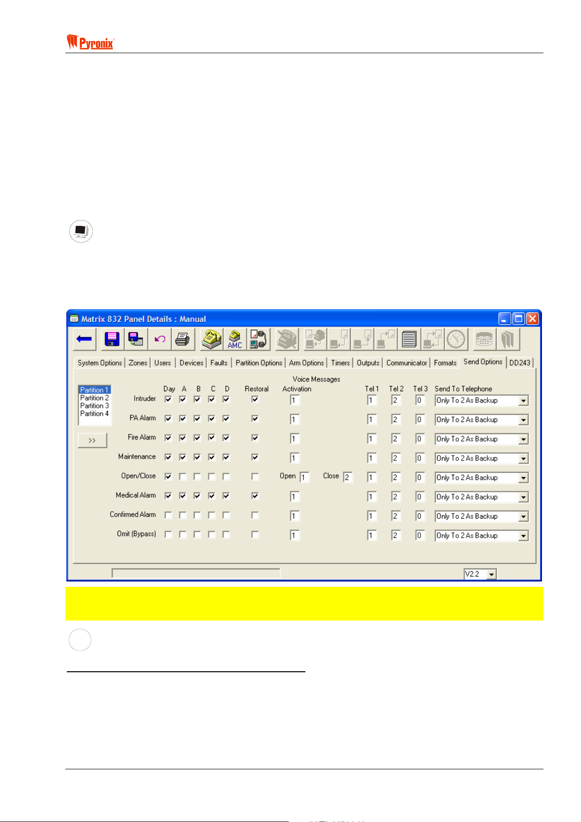
! Matrix 832 / 832+ / 424
8.2.2 BSIA Format Channel Map
Enter BXWW. The current channel map will be displayed. Enter 8 digits from [1 - 8]. An acceptance tone
will be heard after the 8
th
digit has been pressed. All the digits must be different or operation of the BSIA
channels will be unpredictable.
By default the map is 1,2,3,4,5,6,7,8. The first digit is channel 1, the 8
th
digit is channel 8.
1 = Fire, 2 = PA, 3 = Intruder, 4 = Open / Close, 5 = Spare, 6 = Medical, 7 = Confirmed, 8 = Omit.
For example, if omit was required to be transmitted on channel 5 the entry order would be:
1,2,3,4,8,6,7,5.
8.3 Send Options & Group Reporting Sequence
PC Programming Procedure
The PC window below shows the send options for partition 1. On the side of this screen shot is a partition
selection box, containing all 4 partitions. Information in 1 partition can be copied in to other partitions by
selecting a partition number in the partition selection box and pressing the “>>” button.
Once all desired attributes have been chosen press the <save> button and proceed to the next window.
NOTE: The system allows the engineer to split the event reporting to different telephone numbers for
any of the system modes. It is also possible to allocate either the same or different telephone
numbers to each of the partitions.
MEANING
Programmable Options Explanation
System and Arm Modes Event Reporting Allocation
Day - When the panel is disarmed the engineer can chose which events to report to the central monitoring
station from Intruder Alarms, PA alarms, Fire alarms, Maintenance information, Open / Close, Medical,
Confirmed Alarms and omitted (bypassed) zones information.
Arm A - When the panel is armed in Arm A mode the engineer can choose which events to report to the
central monitoring station from Alarms, PA alarms, Fire alarms, Maintenance information, Open / Close,
Medical, Confirmed Alarms and omitted (bypassed) zones information.
RINS428-5 Page 83

Matrix 832 / 832+ / 424
Arm B - When the panel is armed in Arm B mode the engineer can choose which events to report to the
central monitoring station from Alarms, PA alarms, Fire alarms, Maintenance information, Open / Close,
Medical, Confirmed Alarms and omitted (bypassed) zones information.
Arm C - When the panel is armed in Arm C mode the engineer can choose which events to report to the
central monitoring station from Alarms, PA alarms, Fire alarms, Maintenance information, Open / Close,
Medical, Confirmed Alarms and omitted (bypassed) zones information.
Arm D - When the panel is armed in Arm D mode the engineer can choose which events to report to the
central monitoring station from Alarms, PA alarms, Fire alarms, Maintenance information, Open / Close,
Medical, Confirmed Alarms and omitted (bypassed) zones information.
Restoral - When the panel is armed any of the above modes the engineer can choose to enable or disable
events restorals reporting to the central monitoring station from Alarms, PA alarms, Fire alarms, Maintenance
information, Open / Close and Medical information.
Tel1, Tel2, Tel3
The system allows the engineer to allocate 3 different CMS telephone numbers from the 9 numbers available
for reporting each of the following events: Alarms, PA alarms, Fire alarms, Maintenance information, Open /
Close and Medical information.
For instance all events can be sent to Telephone number 1 and 2 and alarm events only to Telephone number
3. In this case Telephone No 1 would be 1
st
CMS number, Telephone No 2 would be 2nd CMS number and
Telephone No 3 would be user pager number.
Group Events Reporting Option
These options allow the engineer to decide which groups of alarms are transmitted to the Central Monitoring
Station in the various modes of the Panel. This option should be used to prevent call jam to the CMS in pick
times:
Only Send To 1 - Events to be sent only to telephone number 1.
Always Send To Both - Events to be sent to both telephone numbers.
Only To 2 As Backup - Events to be sent to telephone number 1 and if no communication acknowledged
send to telephone number 2.
NOTE: If telephone number 3 programmed then the panel will always call this number after the
communication to numbers 1 or 2. If only telephone 3 programmed then the panel will not call.
MX-VOICE Messages
You are able to record up to 8 separate voice messages that can be sent by the MX-Voice Module when an
event has occurred. Each event type (alarm, fire, PA, etc.) may have a voice message number associated
with it. There are 8 event types, although open/close is a special case, and allows a separate message for
both open and close. This means that there can be a total of 9 different triggers for a message, to be
distributed over 8 different messages. However, most systems do not need messages for all 9 events, so this
should not be a problem.
Once you have programmed an alarm type with a voice message, you must associate it with a telephone
number that has been programmed as a voice number. If you only want to send voice messages, programme
Tel 1 as voice protocol. If you wish to send both Contact ID and voice messages, programme Tel 1 and Tel 2
as CID number, and Tel 3 as a voice number. This allows the much faster CID protocol to be sent first.
Since voice messages cannot be acknowledged, they will repeat for 1 minute. Also, because there is no
handshake, it is not possible to know if a call has been picked up, or if the line was engaged. Therefore, you
can program the system with the number of times to dial the number. For example, if the repeat number is 1,
the number will be dialled; the message will play for 1 minute, and then hang up. If the repeat is 2, the number
will be dialled; the message will play for 1 minute, and then hang up. The number will be dialled again, and the
message played for another minute. The next event of telephone number will then be processed. Use this
feature with caution, as it may delay other important messages if the repeat number is too high (maximum of 9
repeats).
Restorals of events (e.g., closing a zone or fixing a fault) do not have voice messages associated with them
(this means that upon restoring an event, no voice message will be sent). Once one voice message of a
specific event type has been sent, that particular message will not be sent again in the same set or unset
period. For example, if you get 4 separate zones being activated in one set period only ONE intruder alarm
voice message will be sent. During that same set period, if a PA goes off, the PA voice message will be sent,
but if a further PA is triggered in the same set period, the second activation will NOT cause a voice message.
This limit is reset each time the panel is either set or unset. The purpose of this is to limit the number of
unwanted voice messages.
Page 84 RINS428-5

! Matrix 832 / 832+ / 424
A
S
Activation
When an event occurs the MX-VOICE transmits the related voice message to the alarm event.
ARMED
ALARM
FAULT
FIRE
SUPPLY
8
8
P.A.READY
TAMPER
DAY
2134
BCD
ET
P.A.
5678
FIRE
FUNC
90
Keypad Programming Procedure
8.3.1 Disarmed Mode Events Send Options
Enter BY followed by one digit for the desired partition number from [1 - 4]. To choose an option use
the
> and ? buttons. To change an option setting, press the C button. To save the changes press B. An
acceptance tone will be heard.
Option Option Off = Alarm LED Off Option On = Alarm LED On Default
1 Alarms are not sent Alarms are sent On
2 PA are not sent PA are sent On
3 Fire are not sent Fire are sent On
4 Maintenance are not sent Maintenance are sent On
5 Open/Close are not sent Open/Close are sent On
6 Medical not sent Medical are sent On
7 Confirmed alarm not sent Confirmed alarm sent Off
8 Omits (Bypass) not sent Omits (Bypass) sent Off
8.3.2 Arm Mode A Events Send Options
Enter BY followed by one digit for the desired partition number from [1 - 4]. To choose an option use
the
> and ? buttons. To change an option setting, press the C button. To save the changes press B. An
acceptance tone will be heard.
Option Option Off = Alarm LED Off Option On = Alarm LED On Default
1 Alarms are not sent Alarms are sent On
2 PA are not sent PA are sent On
3 Fire are not sent Fire are sent On
4 Maintenance are not sent Maintenance are sent On
5 Open/Close are not sent Open/Close are sent Off
6 Medical not sent Medical are sent On
7 Confirmed alarm not sent Confirmed alarm sent Off
8 Omits (Bypass) not sent Omits (Bypass) sent Off
8.3.3 Arm Mode B Events Send Options
Enter BYT followed by one digit for the desired partition number from [1 - 4]. To choose an option use
the
> and ? buttons. To change an option setting, press the C button. To save the changes press B. An
acceptance tone will be heard.
Option Option Off = Alarm LED Off Option On = Alarm LED On Default
1 Alarms are not sent Alarms are sent On
2 PA are not sent PA are sent On
3 Fire are not sent Fire are sent On
4 Maintenance are not sent Maintenance are sent On
5 Open/Close are not sent Open/Close are sent Off
6 Medical not sent Medical are sent On
7 Confirmed alarm not sent Confirmed alarm sent Off
8 Omits (Bypass) not sent Omits (Bypass) sent Off
RINS428-5 Page 85

Matrix 832 / 832+ / 424
8.3.4 Arm Mode C Events Send Options
Enter BYU followed by one digit for the desired partition number from [1 - 4]. To choose an option use
the
> and ? buttons. To change an option setting, press the C button. To save the changes press B. An
acceptance tone will be heard.
Option Option Off = Alarm LED Off Option On = Alarm LED On Default
1 Alarms are not sent Alarms are sent On
2 PA are not sent PA are sent On
3 Fire are not sent Fire are sent On
4 Maintenance are not sent Maintenance are sent On
5 Open/Close are not sent Open/Close are sent Off
6 Medical not sent Medical are sent On
7 Confirmed alarm not sent Confirmed alarm sent Off
8 Omits (Bypass) not sent Omits (Bypass) sent Off
8.3.5 Arm Mode D Events Send Options
Enter BYV followed by one digit for the desired partition number from [1 - 4]. To choose an option use
the
> and ? buttons. To change an option setting, press the C button. To save the changes press B. An
acceptance tone will be heard.
Option Option Off = Alarm LED Off Option On = Alarm LED On Default
1 Alarms are not sent Alarms are sent On
2 PA are not sent PA are sent On
3 Fire are not sent Fire are sent On
4 Maintenance are not sent Maintenance are sent On
5 Open/Close are not sent Open/Close are sent Off
6 Medical not sent Medical are sent On
7 Confirmed alarm not sent Confirmed alarm sent Off
8 Omits (Bypass) not sent Omits (Bypass) sent Off
8.3.6 Restoral Events Send Options
Enter BYW followed by one digit for the desired partition number from [1 - 4]. To choose an option use
the
> and ? buttons. To change an option setting, press the C button. To save the changes press B. An
acceptance tone will be heard.
Option Option Off = Alarm LED Off Option On = Alarm LED On Default
1 Alarms are not sent Alarms are sent On
2 PA are not sent PA are sent On
3 Fire are not sent Fire are sent On
4 Maintenance are not sent Maintenance are sent On
5 Open/Close are not sent Open/Close are sent Off
6 Medical not sent Medical are sent On
7 Confirmed alarm not sent Confirmed alarm sent Off
8 Omits (Bypass) not sent Omits (Bypass) sent Off
Page 86 RINS428-5

! Matrix 832 / 832+ / 424
8.3.7 Allocating Telephone Numbers to Alarm Types in Partitions
Enter BYX followed by one digit for the desired partition number from [1 - 4]. Enter the alarm type from
[1 - 6]*.
[1]* =Alarm, [4]* =Maintenance, [7]* =Confirmed,
[2]* =PA, [5]* =Open/Close [8]* =Omit [bypass]
[3]* =Fire, [6]* = Medical Alarm
Programming for ‘Tel 1’ will follow.
Enter a number from [1 - 9] to select the telephone number programmed in function 650 to use for this alarm
type.
Press
Programming for ‘Tel 2’ will follow.
Enter a number from [1 - 9] to select the telephone number programmed in function 650 to use for this alarm
type.
Press
Programming for ‘Tel 3’ will follow.
Enter a number from [1 - 9] to select the telephone number programmed in function 650 to use for this alarm
type.
Press
Programming for group reporting sequence will follow
Enter a number from [1 - 3]* to select the telephone sequence allocation for numbers 1 & 2.
Press
[1]* =Only send to number 1
[2]* =Both telephone numbers
[3]* =Send to 2 only if 1 is busy
The option will repeat from the beginning. Enter
B to save. An acceptance tone will be played.
B to save. An acceptance tone will be played.
B to save. An acceptance tone will be played.
B to save. An acceptance tone will be played.
BB to exit the option.
NOTE: Telephone numbers 1 & 2 are only affected by the sequence setting. They will generally be
used for reporting to the central station. Telephone number 3 would normally be used to report to a
third party. E.g. Pager or Installer. If a telephone number allocation is not required set the number to
00.
8.3.8 MX Voice Module Support
Enter BYY followed by the partition number [1 - 4]. Enter a number from [1 - 8] to choose an alarm
type as follows:
[1] = Alarm [3] = Fire Alarm [5] = Open / Close [7] = Confirmed
[2] = PA Alarm [4] = Maintenance [6] = Medical [8] = Omits, [Bypass]
Enter a voice message number from [1 - 8] corresponding to the activation event. If the alarm number is
OPEN/CLOSE, also enter the message number for the Close event.
Press
B to confirm the programming. The function will repeat from the beginning. Press BB to exit the
programming function.
8.3.9 Change Number of Voice Dials
Enter BY[. The current number of voice dials will be displayed. Choose a number from [01 - 08]. To
save the changes, press
RINS428-5 Page 87
B. An acceptance tone will be played.

Matrix 832 / 832+ / 424
Section 9: Installing DD243
Installing the Matrix Panel to DD243
The Pyronix Matrix Panel has been carefully designed to incorporate the latest DD243: 2002 features. There
are several ways the Matrix can be programmed and installed to satisfy the DD243 requirements. Each of the
basic methods is outlined below, variations of these methods exist and it is left to the individual installer to
tailor the programming to fit the exact requirements of the installation.
Before any of the DD243 features will work the DD243 Option must be activated. This is achieved by enabling
Option 1 of the DD243 options.
9.2 Zone Mapping
A conflict exists between DD243 and good engineering practice: Sequential confirmation is only allowed
between non-overlapping detectors of the same single technology. Sometimes this is not possible and
therefore the current answer would be to put the overlapping detectors on the same zone input. However this
makes fault-finding and maintenance more difficult. The Matrix allows the Installer to have the best of both
worlds by incorporating Zone Mapping:
Each zone input on the Matrix is allocated a Map number. By default the zone map number is the same as the
zone number, therefore any combination of zones can potentially cause a sequentially confirmed activation. If,
however the installation of detectors with overlapping coverage cannot be avoided, for example two glassbreak detectors in adjoined rooms, the Matrix zones for these two detectors can be assigned the same map
number. If these two detectors activate in a confirmed period, but no other detector does, a confirmed alarm
will not be generated. If one or both detectors activate and then a third detector with a different map number
activates within the confirmation time, a confirmed alarm will be generated. Obviously a confirmed alarm will
also be generated if a detector with a different map number is activated before either of the two detectors with
matching map numbers.
9.3 Means of Setting (Arming) and Unsetting (Disarming)
Installing a Matrix with Keyswitches
The Keyswitch zone can be used to cover DD243 section 6.4.2 - ‘Unlocking the initial entry door unsets the
IAS’. Using a keyswitch and a shunt lock on the initial entry door will arm the panel when the lock is closed.
In addition, it will disarm the panel when the lock is opened.
Installing a Matrix with Push to Arm
The Set zone type has been provided to cover two sections of DD243:
DD243 Section 6.3b specifies an externally mounted push button; such a button can be normally open or
normally closed, by changing the zone polarity when programming the zone (see section 8.6.2 zone
attributes). Push to Arm is enabled by changing the set method for the desired part set in Arm Options (see
section 8.11). If this method is used, the complementary entry method would normally be DD243 section
6.4.4 - ‘Opening the initial entry door disables all forms of confirmation’, this is enabled by setting option 3 of
the DD243 options.
DD243 Section 6.3a specifies a key operated shunt lock. Shunt locks have an internally mounted microswitch, which allows the Matrix to detect when the lock is opened and closed. The polarity of the micro-switch
is unimportant as the zone polarity can be changed in zone programming. The complementary entry method
would normally be DD243 section 6.4.3 – ‘Unlocking the initial entry door disables all forms of confirmation’;
this is enabled by setting option 2 of the DD243 options.
Installing a Matrix with Final Door Set
The Entry Exit zone can be used to end the exit timer; this covers DD243 section 6.3c – ‘Protective switch
fitted to the final exit door’. Final door is enabled by changing the set method for the desired part set in Arm
Options to Final Exit (see section 8.11). If this method is used, the complementary entry method would
normally be DD243 section 6.4.4 - ‘Opening the initial entry door disables all forms of confirmation’, this is
enabled by setting option 3 of the DD243 options.
Page 88 RINS428-5

! Matrix 832 / 832+ / 424
Installing a Matrix with Proximity Readers
Pyronix Proximity Readers are available which directly connect to the Matrix Keypad Bus. This installation
method satisfies DD243 section 6.3d – ‘Portable ACE’ and DD243 section 6.4.4 - ‘Completion of unsetting is
achieved using portable ACE’. Also see DD243 section A.1.
Installing a Matrix with ‘When Unsetting is carried out in conjunction with an ARC’
The Matrix supports remote Arming and Disarming via the UDL software, this covers DD243 sections 6.3e
and 6.4.6.
Note: DD243 states that for some of the above methods, any limitations should be made clear to the
customer.
9.4 Resetting Following an Alarm Condition
DD243 section A.4 states that unless the system has been installed in accordance with DD243 sections
6.4.2, 6.4.3 or 6.4.6, after a confirmed alarm has been transmitted the system can only be reset by means not
normally available to the customer. This is catered for in two ways in the Matrix:
1. Engineer reset (see section 7.10)
2. Anti-code reset (see section 7.10)
Both Engineer and Anti-code reset can be configured to activate after a confirmed alarm only to satisfy DD243
section A.4 or to activate after any alarm to satisfy other requirements.
If both Engineer and Anti-code are enabled, either code will reset the system. This is useful so the system
can be reset over the telephone in conjunction with the user without giving out the Engineer code, or on-site
by the Installer using the Engineer code.
9.5 Mis-Operation Signals
Reporting a Mis-operation Signal
The Matrix panel supports sending a mis-operation in the following way;
If open close reporting is enabled, the ARC should follow the DD243 section 7.4.3b i.e. during the alarm
filtering delay the ARC receives a signal indicating that the system is unset.
If open close reporting is disabled then the option ‘Send Open After Alarms’ should be enabled (see section
9.1). Again, the ARC should follow the DD243 section 7.4.3b i.e. during the alarm filtering delay the ARC
receives a signal indicating that the system is unset.
See DD243 section 6.2.2.
Note – Send open after alarms is designed to work with the Contact ID reporting format, if BSIA or an
external communicator is used, the Central monitoring station should be told to interpret a restoral of
the Alarm channel as a mis-operation signal.
RINS428-5 Page 89

Matrix 832 / 832+ / 424
9.6 DD243 Options Table
The table below summarizes the expected settings for each method of installation to comply with DD243.
DD243 Settings Means of Unsetting
Arm Zone Operation Entry Zone Operation Entry Time End
Unlocking the Initial Entry
door Unsets the IAS
Unlocking the Initial Entry
Door Disables All Means
Of Confirmation
Opening The Initial Entry
Door Disables All Means
Of Confirmation
Completion Of Unsetting
Is Achieved Using A
Portable ACE
Unsetting Is Carried Out
In Conjunction With An
ARC
* - This setting is unimportant as the panel will be unset before entry.
Normal Normal Re-enable Confirmation*
Disable Confirmation Normal
Normal Disable Confirmation
Normal Disable Confirmation Re-enable Confirmation
Normal Normal Re-enable Confirmation*
Do Not Re-enable
Confirmation
Do Not Re-enable
Confirmation
Auto-Omitting Zones
Any zones which are open at the end of the confirmation time can be omitted. If the zone was programmed
as Entry/Exit then any zones programmed as access will be treated like Entry/Exit zones while the Entry/Exit
zone(s) are omitted
PC Programming Procedure
The PC window below shows how to program the DD243 options from PC software. Once an option has been
chosen, press the <save> button and proceed to the next window.
Page 90 RINS428-5

! Matrix 832 / 832+ / 424
MEANING
DD243 Options
Enable DD243 Options
This is the first option in the DD243 section. This option needs to be enabled before any of the remaining
options will be considered. Change this option to [Yes] to allow the remaining DD243 features to be used. The
factory default setting is [No].
Arm Zone Operation
This is option two in the DD243 section. It determines how an Arm Zone affects confirmed alarms.
Normal Operation - The Arm Zone will behave as normal. Confirmed alarms will not be disabled by Arm
Zones (default).
Disable Confirmation - When the Arm zone is opened or the Entry Timer is running, confirmed alarms will be
disabled.
Entry Timer Operation
This is option three in the DD243 section. It determines how the Entry timer affects confirmed alarms.
Normal Operation - The Entry Timer will behave as normal. Confirmed alarms will not be disabled by the
Entry Timer (default).
Disable Confirmation - While the Entry Timer is running confirmed alarms will be disabled.
Auto Omit Open Zones
This is option four in the DD243 section. It determines when open zones will be omitted.
At End Of Confirmation Time – Any zones that are open when the confirmation timer ends will be omitted. If
any open zone is programmed as an Entry/Exit zone, all Access zones will be turned into Entry/Exit zones for
the remaining time the panel is set. This allows the user to enter the building without setting the alarm system
off again.
At End Of Bell Time – Any zones that are open when bell timer ends will be omitted. There is no attempt to
convert Access zones into Entry/Exit zones. The panel will go into alarm if the user enters the building straight
into an Access zone.
Zone Expander Tamper
This is option 5 in the DD243 section. It decides if a missing zone expander sends a confirmed or unconfirmed
alarm.
Unconfirmed Alarm - If Tamper On Device Missing (see System Options 2) is set then only an unconfirmed
alarm is activated (default).
Confirmed Alarm - If Tamper On Device Missing (see System Options 2) is set then both an unconfirmed
and confirmed alarm are activated.
Fire, PA and Medical Keys
This is option 6 in the DD243 section. It allows the Fire, PA and Medical keys to be disabled, if required.
Enabled - The Fire, PA and Medical keys are enabled (default)
Disabled - The Fire, PA and Medical keys are disabled (see System Options 1).
Entry Time End
This is option 7 in the DD243 section. It determines whether sequential confirmation is re-enabled at the end
of the entry time.
Do not re-enable confirmation - This option should be selected if either opening or unlocking the initial entry
door enables confirmation.
Re-enable confirmation - This option should be selected if disarming is achieved by using a portable ACE.
RINS428-5 Page 91

Matrix 832 / 832+ / 424
9.7 DD243 Options 1
Enter BZ. Use the > and ? keys to select an option to change.
To change the state of the option, press the
C key once. Repeated pressing of the C key toggles the state.
Option Off / LED Off On / LED On Default
Enable DD243 Options 2-8 No Yes Off
1
Open set zone stops confirmation No Yes On
2
Open entry zone stops confirmation No Yes Off
3
Auto Omit Open Zones At End Of Bell Time At End Of
4
Lost zone expander causes confirmed
5
alarm
Fire, PA and Medical keys disabled No Yes Off
6
Entry time end Re-enable
7
8 Spare
To save all changes press the B key. An acceptance tone will be played and the function will end.
No Yes Off
confirmation
Confirmation Time
Do not re-enable On
At End Of Bell Time
9.8 DD243 Zone Map
Enter BZT. Enter the zone number [01 - 32]. An acceptance tone will be heard and the current zone
map will be displayed. Enter a new zone map [01 - 99] for this zone. Press
confirmation tone will be played.
B to save the new value. A
9.9 DD243 Partition Confirmation Times
Enter BZV. Enter a partition number [1 - 4]. An acceptance tone will be heard and the current
confirmation time for this partition will be displayed. Enter the new confirmation time [01 - 99] in minutes for
this partition. Press
B to save the new value. A confirmation tone will be played.
Page 92 RINS428-5

! Matrix 832 / 832+ / 424
Section 10: Events Memory Log & System Maintenance
The Matrix 832, 832+ & 424 control panels have an event memory log of 300 events. These are displayed
with time and date and can be read from both LCD and Icon keypads or using the UDL software from a PC.
10.1 Reading The Event Log
PC Programming Procedure
Downloading the Log from the Panel
Connect to the control panel with modem or using the RS232 output. To retrieve data from the panel log press
on the <Read the log> button
Before downloading the log you can choose events to view as shown in the window below:
MEANING
Programmable Options Explanation
from the tab of the main programming window.
Read Log Options
Last Log - Will not download a new log from the panel but will instead show the stored logs.
All the log - This will download all 300 events from the panel.
The last 50 events
The last 100 events
The last number of events – Any a value between 1 and 300.
Download New Events
Complete Log of all events that have occurred in the panel. Events are not added to the Complete Log if you
use any of the other options. It is highly recommended that you perform a New Events download of the log as
this way you will get a complete history (if the log wraps around before you download events or someone
does a log reset then events might be lost) of the panel. Downloading the log in any of the other ways will not
add the downloaded events to the complete log. See “Reading the Complete log” below.
If the transfer fails then the program will show an error message. If this happens select the option again.
The PC window below shows alarm events that have been entered into the log.
RINS428-5 Page 93
- When you use the New Events option then the events you download are added to a

Matrix 832 / 832+ / 424
A
S
MEANING
Programmable Options Explanation
Last – This option enables the last log to be down loaded
Previous 1, Previous 2, Previous 3 – This shows the previous 3 logs downloaded
Complete History – This shows all events downloaded using the <new events> Download option.
Partitions To View – Select the partitions, which you want to view the log event in.
[0] – System events
[1] – Events for Partition 1
[2] – Events for Partition 2
[3] – Events for Partition 3
[4] – Events for Partition 4
ARMED
ALARM
FAULT
SUPPLY
FIRE
8
8
P.A.READY
TAMPER
DAY
2134
BCD
ET
P.A.
5678
FIRE
FUNC
90
Keypad Programming Procedure
10.1.2 Viewing Event Log Memory
To view the event log use the event tables below to understand the meaning of the symbols displayed on the
keypad.
Enter
BU. Use the > and ? buttons to scroll through the events.
*Denmark, Norway, Finland & Sweden Only
Access zones are logged during the entry period.
Logging of zone events is limited to three per zone, including zone tampers.
Page 94 RINS428-5
 Loading...