

KX10DP
10m Digital Pet PIR Detector
0845 6434 999 (UK). +44(0)1709 535 225 customer.support@pyronix.com www.pyronix.com Pyronix Limited, Pyronix House, Braithwell Way, Hellaby, Rotherham, S66 8QY, UK RINS1600-4
ENGLISH
(Diagram references)
Technical Specification
Warranty
Product Warning Information
This product is sold subject to our standard warranty conditions and is warranted
against defects in workmanship for a period of ve years.
For further warranty information visit: www.pyronix.com/warranty
For electrical products sold within the European Community. At the end of the
electrical products life, it should not be disposed of with household waste. Please
recycle where facilities exist. Check with your Local Authority or retailer for recycling
advice in your country. The declaration of conformity may be consulted at
www.pyronix.com/product-compliance.php
This product is approved for use in the Residential,
Commercial and Light Industrial Environments.
EOL
The KX15DD Printed Circuit Board
®
D
AUTO HI
LOW AUTO
AUTO HI
LOW AUTO
==
=
LOW
Model: KX10DP
Colour: White
LED Colour: Blue
Casing: 3mm ABS, 0.4mm HDPE in lens area
Detection Method: Digital Signal Processing
PIR Sensitivity: Auto (Default), Low
Max Pet Tolerance: 24Kg (55lbs)
Temperature Compensation: Digital
Detection Range: 10m
Detection Speed: 0.3 - 3.0 m/s
Operating Voltage: 9 - 16V DC 13.8V DC typical
Current Consumption: 13mA @ 12V (Min), 16mA @12V (Max)
Relay Output: 50mA 60V DC, 42 VAC (RMS)
Contact Resistance: < 10 ohms
Mounting Height: 1.8 - 2.4m (mount at 2.1m for INCERT)
Tamper Switch: 12V 50mA
Storage Temperature: -40oC to 80oC
Certied Operating Temperature: -10oC to 40oC
Nominal Working Temperature: -30oC to 70oC
Accessories: Wall and Ceiling brackets
Emissions: EN55022 Class B
Immunity: EN50130-4
PCB
DEFAULT
PREDEFINITO
HIGH / LOW
B
START
f) Back
Tamper
C D
F G
E
1
A
B
2
C
D
3
A
LED ON LED OFF
1
A
B
C
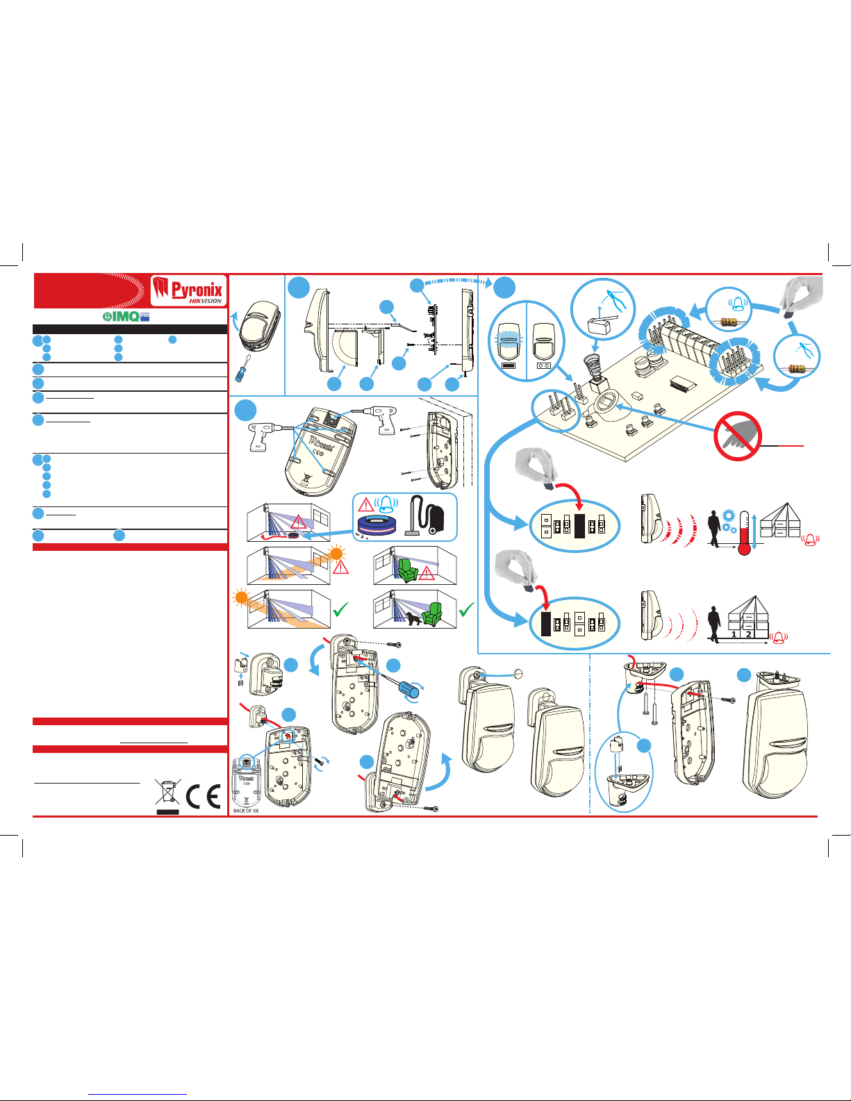
Printed Circuit Board (PCB)
LED light pipe / diuser
Lens
D
E
F
G
Lens holder
PCB screw
Captive nut
Casing screw
2
33
34
PCB conguration (Including PIR sensitivity)
Mounting Options
The 10m Pet Lens. Dimensions and Weight
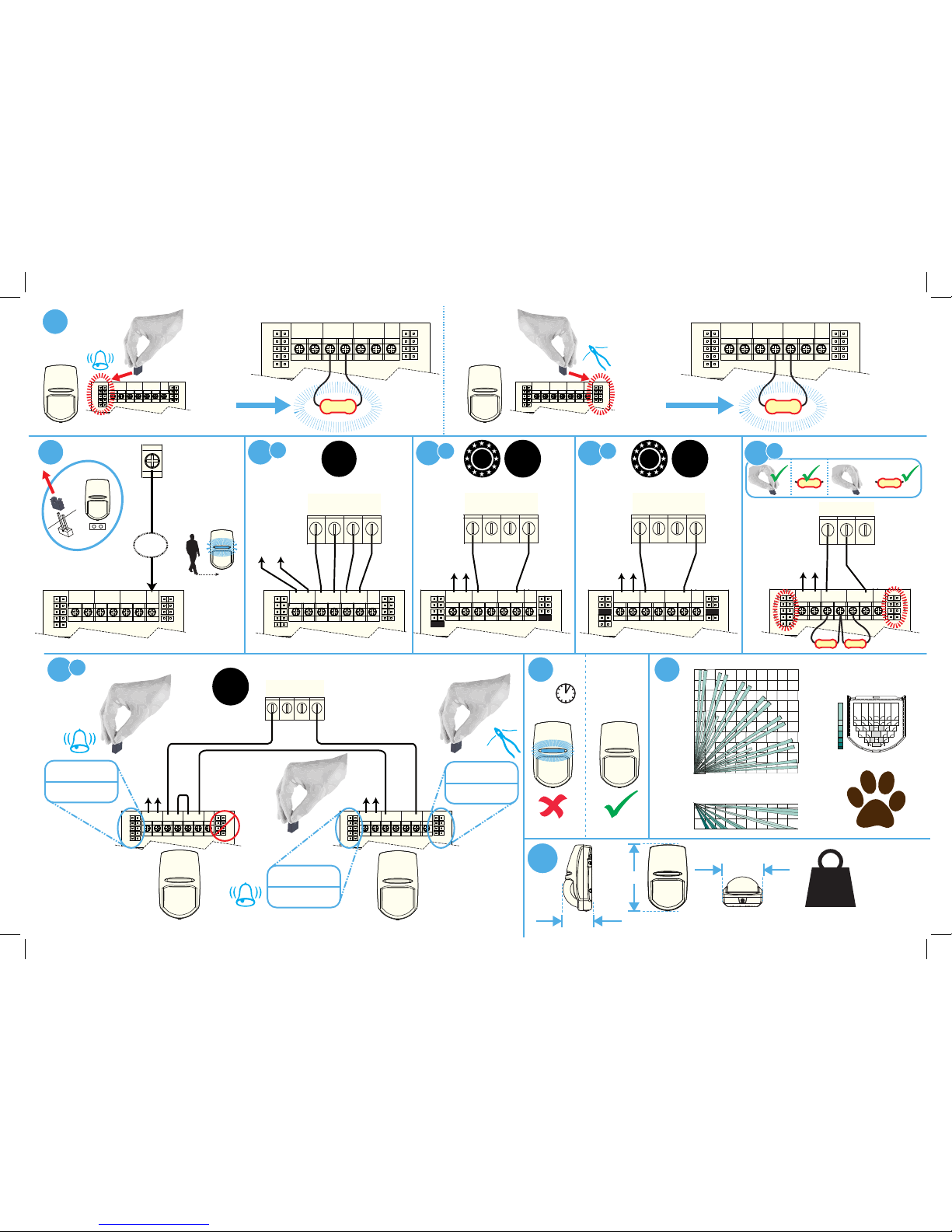
EOL Resistor Headers: The KX10DP has 2 sets of header pins (as shown). These
headers are used to select the End of Line resistance for EOL wiring applications.
NOTE: If EOL wiring is not used, leave the headers OFF.
Remote LED Enable: This is used when the LED is disabled via the LED ON/OFF
link. To enable this feature the LED terminal needs to be connected to an output
on the control panel. When the system is in walk test mode the output should
be at 0v. For Pyronix panels the output would usually be programmed as
‘Remote LED enable’.
Powering Up: When the detector is rst powered up, it will run through a self-test
routine (indicated by the ashing blue LED). Once the LED goes out the detector
is ready to use.
35
36
37
38
39
A
B
C
D
E
N/C - Normally Closed Wiring (EXAMPLE ONLY, SEE CONTROL PANEL INSTRUCTIONS)
PCX DEOL Wiring (EXAMPLE ONLY, SEE CONTROL PANEL INSTRUCTIONS)
EURO DEOL Wiring (EXAMPLE ONLY, SEE CONTROL PANEL INSTRUCTIONS)
Generic Control Panel (shows resistor locations)
2x Double End of Line Detectors to One Input (SEE CONTROL PANEL INSTRUCTIONS)
+
+
+
+
+
+
+
+
PIR
TAMPER
TAMPER
5K6, 4K7, 2K2, 1K
ALARM
6K8, 5K6,
4K7, 2K2, 1K
A
B
B
C
3
AUTO
EN50131-2-2:2008
EN50131-1:2006+A1:2009
PD6662:2010
Security Grade (SG) 2
Environmental Class (EC) II
SENSITIVIT
Auto
EOL Resistor Headers
s of header pins on the PCB, one on
®
®
E
ALARM
CONTROL
PANEL
+ -
KX
6K8
5K6
4K7
2K2
1K
5K6
4K7
2K2
1K
TAMPERALARM
ALARM TAMPER
Control Panel Output
(0v in walk test)
LED
+ -
6K8
5K6
4K7
2K2
1K
5K6
4K7
2K2
1K
TAMPERALARM
ALARM TAMPER LED
NOT READY READY
50 mm
117 mm
69 mm
125g
(4.4 oz)
=
60s
<24kg
9m
8m
7m
6m
5m
4m
3m
2m
1m
2m 3m 4m 5m 6m 7m 8m 9m
1m
10m
10m
HORIZONTAL COVERAGE
2.4m
VERTICAL COVERAGE
2m 3m 4m 5m 6m 7m 8m 9m
1m
10m
10m VOLUMETRIC LENS
With Pet Mask
O
85
56 zones
6 planes
RLNS074
Mount at 2.1m
for INCERT
compliance
4
5 6
ALARM
CONTROL
PANEL
+ -
KX
6K8
5K6
4K7
2K2
1K
5K6
4K7
2K2
1K
TAMPERALARM
ALARM TAMPER
Control Panel Output
(0v in walk test)
LED
ALARM
CONTROL
PANEL
+ -
KX
6K8
5K6
4K7
2K2
1K
5K6
4K7
2K2
1K
TAMPERALARM
ALARM TAMPER
Control Panel Output
(0v in walk test)
LED
ALARM
CONTROL
PANEL
+ -
KX
6K8
5K6
4K7
2K2
1K
5K6
4K7
2K2
1K
TAMPERALARM
ALARM TAMPER
Control Panel Output
(0v in walk test)
LED
A
6
B
6
C
6
D
6
E
7
9
8
A A T T
EOL INPUT 1
A A T T
EOL INPUT 1
+12V 0V
+12V 0V
ALARM
TAMPER
PCX / EURO
PCX
ALARM
CONTROL
PANEL
+ -
6K8
5K6
4K7
2K2
1K
5K6
4K7
2K2
1K
TAMPERALARM
ALARM TAMPER
Control Panel Output
(0v in walk test)
LED
A A T T
EOL INPUT 1
+12V 0V
EURO: 4K7
PCX:
1K
PCX / EURO
(LINK)
ALARM
CONTROL
PANEL
+ -
6K8
5K6
4K7
2K2
1K
5K6
4K7
2K2
1K
TAMPERALARM
ALARM TAMPER
Control Panel Output
(0v in walk test)
LED
+12V 0V
ALARM
ALARM
TAMPER
END
ALARM
CONTROL
PANEL
+ -
KX
6K8
5K6
4K7
2K2
1K
5K6
4K7
2K2
1K
TAMPERALARM
ALARM TAMPER
Control Panel Output
(0v in walk test)
LED
ALARM:
6K8,
5K6,
4K7,
2K2,
1K
+ -
6K8
5K6
4K7
2K2
1K
5K6
4K7
2K2
1K
TAMPERALARM
ALARM TAMPER LED
=
TAMPER:
5K6,
4K7,
2K2,
1K
N/C
2
DEOL
ALARM
CONTROL
PANEL
+ -
KX
6K8
5K6
4K7
2K2
1K
5K6
4K7
2K2
1K
TAMPERALARM
ALARM TAMPER
Control Panel Output
(0v in walk test)
LED
A A T T
EOL INPUT 1
+12V 0V
EURO
2
DEOL
ALARM
CONTROL
PANEL
+ -
6K8
5K6
4K7
2K2
1K
5K6
4K7
2K2
1K
TAMPERALARM
ALARM TAMPER
Control Panel Output
(0v in walk test)
LED
Z1 COM Z2
+12V 0V
GENERIC CONTROL PANEL
CENTRALE GENERICA
KX
DEOL
EURO: 4K7
PCX:
1K
EURO: 2K2
PCX:
1K
LED OFF
... .
0V =
PANEL OUTPUT
USCITA DELLA
CENTRALE
+

0845 6434 999 (UK). +44(0)1709 535 225 customer.support@pyronix.com www.pyronix.com Pyronix Limited, Pyronix House, Braithwell Way, Hellaby, Rotherham, S66 8QY, UK
The following languages are available online via the QR code: Bulgarian, Czech, Danish, German, Greek, Spanish, Finnish, French, Croatian, Hungarian, Italian, Dutch, Norwegian, Polish, Portuguese, Romanian, Russian, Slovak, Slovenian, Serbian, Swedish
KX10DP
Digitaler PIR-Tiermelder (10 m)
KX10DP
Digitale -PIR-huisdierendetector, 10 m
KX10DP
Détecteur PIR numérique tolérant aux
animaux domestiques, portée 10 m
KX10DP
Rilevatore PIR digitale 10 m, animali domestici
DEUTSCH
(Grafikverweise)
Technische Daten
Gewährleistung
Produkthinweis
Dieses Produkt wird mit unseren standardmäßigen Gewährleistungsbedingungen
verkauft und hat eine 5-jährige Gewährleistung hinsichtlich Fertigungsmängeln.
Weitergehende Informationen hierzu nden Sie unter: www.pyronix.com/warranty
In der Europäischen Gemeinschaft verkaufte Elektroartikel sollten am Ende ihrer
Nutzungsdauer nicht im Hausmüll entsorgt werden, sondern bei den dafür
vorgesehenen Annahmestellen abgegeben werden. Informieren Sie sich bei der
zuständigen Behörde oder Ihrem Händler über die Recyclingmöglichkeiten in Ihrem
Land. Die Konformitätserklärung nden Sie unter
www.pyronix.com/product-compliance.php
Dieses Produkt ist für die Benutzung in
Wohnbereichen, Geschäfts- und Gewerbebereichen
sowie in der Leichtindustrie zugelassen.
Modell: KX10DP
Modell: Weiß
LED-Farbe: Blau
Gehäuse: 3 mm ABS, 0,4 mm HDPE im Linsenbereich
Detektionsverfahren: Digitale Signalverarbeitung
PIR-Empndlichkeit: Automatisch (Standard), Niedrig
Max. Objekttoleranz: 24 kg
Temperaturausgleich: Digital
Detektionsbereich 10 m
Detektionsgeschwindigkeit: 0,3 - 3,0 m/s
Betriebsspannung: 9 - 16 V DC; 13,8 V DC typisch
Leistungsaufnahme: 13 mA bei 12 V (min.), 16 mA bei 12 V (max.)
Relaisausgang 50 mA, 60 V DC, 42 VAC (e.)
Kontaktwiderstand: <10 Ohm
Montagehöhe: 1,8-2,4 m (Montagehöhe für INCERT 2,1 m)
Sabotageschalter: 12 V, 50 mA
Lagertemperatur: -40°C bis 80°C
Zertizierte Temperatur: -10°C bis 40°C
Nennbetriebstemperatur: -30°C bis 70°C
Zubehör: Wand- und Deckenhalterung
Emissionen: EN55022 Klasse B
Störfestigkeit: EN50130-4
1
A
B
C
Leiterplatte
LED-Lichtleiter / -verteiler
Linse
D
E
F
G
Linsenhalterung
Leiterplattenschraube
Kägmutter
Gehäuseschraube
2
33
34
Leiterplattenkonguration (inkl. PIR-Empndlichkeit)
Montageoptionen
10-m-Tierlinse Abmessungen und Gewicht
EOL-Widerstandsanschlüsse: Der KX10DP hat zwei Gruppen von Stiftleisten
(siehe Abb.). Diese Anschlüsse dienen zur Auswahl des Leitungsabschlusswiderstands bei Abwendungen mit EOL-Verdrahtung. HINWEIS: Lassen Sie die
Anschlüsse auf OFF, wenn keine EOL-Verdrahtung verwendet wird.
Fern-LED aktivieren: Wird benutzt, wenn die LED über die Verknüpfung LED
ON/OFF deaktiviert wird. Um diese Funktion zu aktivieren, muss die
LED-Anschlussklemme mit einem Ausgang der Steuerzentrale verbunden sein.
Wenn sich das System im Gehtest-Modus bendet, sollte der Ausgang 0 V
betragen. Bei Pyronix-Zentralen ist der Ausgang normalerweise als „Fern-LED
aktivieren“ programmiert.
Einschalten: Wenn der Melder erstmals eingeschaltet wird, führt er eine
Selbsttestroutine durch (angezeigt durch eine blinkende blaue LED). Wenn die
LED erlischt, ist der Melder betriebsbereit.
35
36
37
38
39
A
B
C
D
E
N/C - Normally Closed-Verdrahtung (NUR BEISPIEL, SIEHE STEUERZENTRALEN-AN-
WEISUNGEN)
PCX DEOL-Verdrahtung (NUR BEISPIEL, SIEHE STEUERZENTRALEN-ANWEISUNGEN)
EURO DEOL-Verdrahtung (NUR BEISPIEL, SIEHE STEUERZENTRALEN-ANWEISUNGEN)
Allgemeine Steuerzentrale (zeigt Widerstandsanordnung)
2x DEOL-Melder zu Einzeleingang
(SEE CONTROL PANEL INSTRUCTIONS)
EN50131-2-2:2008
EN50131-1:2006+A1:2009
PD6662:2010
Sicherheitsstufe (SG) 2
Umweltklasse (EC) II
NEDERLANDS
(Diagramverwijzingen)
Technische specificatie
Garantie
Waarschuwingsinformatie voor dit product
Dit product wordt verkocht onder onze standaardgarantievoorwaarden en heeft
gedurende een periode van vijf jaar een garantie op fabricagefouten.
Voor meer informatie over de garantie gaat u naar: www.pyronix.com/warranty
Voor elektrische producten die binnen die Europese Unie worden verkocht:
Elektrische producten mogen aan het einde van hun levensduur niet worden
weggegooid bij het huishoudelijk afval. Lever ze indien mogelijk in bij een locatie
voor recycling. Informeer bij uw lokale instantie of de verkoper naar de
recyclingmogelijkheden in uw land. De conformiteitverklaring is te vinden op
www.pyronix.com/product-compliance.php
Dit product is goedgekeurd voor gebruik in
huishoudelijke, commerciële en licht-industriële
omgevingen.
Model: KX10DP
Kleur: Wit
LED-kleur: Blauw
Behuizing: 3 mm ABS, 0,4 mm HDPE in lensgebied
Detectiemethode: Digitale signaalverwerking
Gevoeligheid PIR: Auto (standaard), laag
Max. tolerantie huisdieren: 24 kg
Temperatuurcompensatie: Digitaal
Detectiebereik: 10 m
Detectiesnelheid: 0,3 - 3,0 m/s
Bedrijfsspanning: 9 - 16 V gelijkstroom 13,8V gelijkstroom typisch
Stroomverbruik: 13 mA bij 12 V (min.), 16 mA bij 12 V (max.)
Relaisoutput: 50 mA 60 V gelijkstroom, 42 V wisselstroom (RMS)
Contactweerstand: < 10 ohm
Plaatsingshoogte: 1,8 - 2,4 m (montage op 2,1 m voor INCERT)
Sabotageschakelaar: 12 V 50 mA
Opslagtemperatuur: -40°C tot 80°C
Gecerticeerde bedrijfstemperatuur: -10°C tot 40°C
Nominale werktemperatuur: -30°C tot 70°C
Accessoires: Muur- en plafondbeugels
Emissies: EN55022 klasse B
Immuniteit: EN50130-4
1
A
B
C
Printplaat
LED-lichtpijp/diusor
Lens
D
E
F
G
Lenshouder
Schroef printplaat
Moer
Behuizingsschroef
2
33
34
Printplaatconguratie (inclusief gevoeligheid PIR)
Montageopties
De huisdierenlens met een bereik van 10 m. Afmetingen en gewicht
Uiteinden EOL-weerstand: De KX10DP is voorzien van 2 sets pinnen aan de
uiteinden (zoals afgebeeld). Deze eindstukken worden gebruikt om de
EOL-weerstand (End Of Line) te selecteren voor toepassingen met EOL-bedrading.
OPMERKING: Als de EOL-bedrading niet wordt gebruikt, moet u de
eindstukken NIET plaatsen.
LED op afstand inschakelen: Wordt gebruikt wanneer de LED wordt
uitgeschakeld via de AAN/UIT-koppeling voor de LED. Als u deze functie wilt
inschakelen, moet de LED-terminal worden aangesloten op een output op het
bedieningspaneel. Wanneer de looptestmodus van het systeem actief is, moet op
de uitgang 0 V staan. Voor Pyronix-panelen wordt de output doorgaans
geprogrammeerd als 'LED op afstand inschakelen'.
Inschakelen: wanneer de detector voor het eerst wordt ingeschakeld, doorloopt
deze een zelftest (aangegeven door het knipperen van de blauwe LED). Zodra de
LED dooft, is de detector klaar voor gebruik.
35
36
37
38
39
A
B
C
D
E
N/C - NorVOORBEELD; RAADPLEEG DE INSTRUCTIES VOOR HET BEDIENINGSPANEEL
)
PCX DEOL-bedrading (VOORBEELD; RAADPLEEG DE INSTRUCTIES VOOR HET
BEDIENINGSPANEEL)
EURO DEOL-bedrading (VOORBEELD; RAADPLEEG DE INSTRUCTIES VOOR HET
BEDIENINGSPANEEL)
Algemeen bedieningspaneel (toont de weerstandslocaties)
2x dubbele EOL-detectors voor één input
(RAADPLEEG DE INSTRUCTIES VOOR HET
BEDIENINGSPANEEL)
EN50131-2-2:2008
EN50131-1:2006+A1:2009
PD6662:2010
Beveiligingsniveau 2
Milieuklasse II
FRANÇAIS
(Références des schémas)
Spécifications techniques
Garantie
Product Warning Information
Ce produit est vendu en étant soumis à nos conditions de garantie standard. Il est
donc garanti contre les malfaçons pour une période de cinq ans.
Pour plus d'informations sur la garantie, rendez-vous sur :
www.pyronix.com/warranty
Pour les produits électriques vendus au sein de la Communauté Européenne. Les
produits électriques en n de vie ne doivent pas être mis au rebut avec les déchets
ménagers. Veuillez recycler auprès des centres de recyclage existants. Consultez vos
autorités locales ou votre revendeur local pour obtenir des informations sur le
recyclage dans votre pays. Vous pouvez consulter la déclaration de conformité sur
www.pyronix.com/product-compliance.php
L'utilisation de ce produit est approuvée pour les
environnements résidentiels, commerciaux et
d'industrie légère.
Modèle : KX10DP
Couleur : blanc
Couleur de LED : bleu
Boîtier : 3 mm d'ABS, 0,4 mm de HDPE autour de l'objectif
Méthode de détection : traitement de signaux numériques
Sensibilité PIR : Auto (par défaut), Faible
Tolérance max. aux animaux : 24 kg (55 livres)
Compensation de température : numérique
Portée de détection : 10 m
Vitesse de détection : 0,3 à 3,0 m/s
Tension de fonctionnement : 9 à 16 VCC, 13,8 VCC typiques
Consommation électrique : 13 mA @ 12 V (min.), 16 mA @ 12 V (max.)
Sortie du relais : 50 mA @ 60 VCC, 42 VCA (RMS)
Résistance de contact : < 10 ohms
Hauteur de xation : 1,8 à 2,4 m (xation à 2,1m pour INCERT)
Interrupteur SABOTAGE : 12 V, 50 mA
Température d'entreposage : --40 °C à 80 °C
Température de fonctionnement certiée : -10 °C à 40 °C
Température de fonctionnement nominale : -30 °C à 70 °C
Accessoires : Support de plafond et support mural
Émissions : EN55022 Classe B
Immunité : EN50130-4
1
A
B
C
Circuit imprimé (PCB)
Diuseur/conducteur de
lumière à LED
Objectif
D
E
F
G
Porte-objectif
Vis du PCB
Écrou captif
Vis du boîtier
2
33
34
Conguration du PCB (comprenant la sensibilité PIR)
Options de xation
Objectif tolérant aux animaux domestiques, 10 m
Dimensions et poids
Embases de résistance EOL : Le KX10DP est équipé de 2 jeux de broches d'embase
(comme illustré). Ces embases sont utilisées pour choisir la résistance en
Extrémité de ligne des applications de câblage EOL. REMARQUE : si vous
n'utilisez pas de câblage EOL, laissez les embases désactivées.
Activation de la LED à distance : Cette fonction s'utilise lorsque la LED est
désactivée, via la liaison d'activation/de désactivation de la LED. Pour activer cette
fonctionnalité, la borne LED doit être connectée à une sortie du panneau de
commande. Lorsque le système est en mode Essai de marche, la sortie doit être à
0 V. Pour les panneaux Pyronix, la sortie sera généralement réglée sur « Activation
de la LED à distance ».
Mise sous tension : Lorsque le détecteur est mis sous tension pour la première
fois, il exécute une routine de test automatique (indiquée par le clignotement
bleu de la LED). Une fois que la LED s'éteint, le détecteur est prêt à l'emploi.
35
36
37
38
39
A
B
C
D
E
N/C - Câblage normalement fermé (UNIQUEMENT EN GUISE D'EXEMPLE,
REPORTEZ-VOUS AUX INSTRUCTIONS DU PANNEAU DE COMMANDE)
Câblage DEOL PCX (UNIQUEMENT EN GUISE D'EXEMPLE, REPORTEZ-VOUS AUX
INSTRUCTIONS DU PANNEAU DE COMMANDE)
Câblage DEOL EURO (UNIQUEMENT EN GUISE D'EXEMPLE, REPORTEZ-VOUS AUX
INSTRUCTIONS DU PANNEAU DE COMMANDE)
Panneau de commande générique (indiquant les emplacements des résistances)
2 détecteurs à résistances à double extrémité de ligne au niveau d'une entrée
(VOIR LES INSTRUCTIONS DU PANNEAU DE COMMANDE)
EN50131-2-2:2008
EN50131-1:2006+A1:2009
PD6662:2010
Classe de sécurité (SG) 2
Classe environnementale (CE) II
ITALIANO
(Riferimenti diagramma)
Specifiche tecniche
Garanzia
Informazioni e avvertenze sul prodotto
Questo prodotto è coperto dalle condizioni di garanzia standard ed è garantito
contro difetti di fabbricazione per un periodo di cinque anni.
Per ulteriori informazioni sulla garanzia visitare: www.pyronix.com/warranty
Per i prodotti elettrici venduti all'interno della Comunità Europea. Al termine della
vita utile, i dispositivi elettrici non devono essere smaltiti con i riuti domestici. Si
raccomanda di conferirli per il riciclo, ove siano presenti le apposite strutture.
Vericare con le autorità locali o il rivenditore le norme di riciclaggio vigenti nel
proprio paese. La dichiarazione di conformità può essere consultata all’indirizzo
www.pyronix.com/product-compliance.php
Questo prodotto è approvato per l’uso in ambienti
residenziali, commerciali e industria leggera.
Modello: KX10DP
Colore: Bianco
Colore LED: Blu
Custodia: 3 mm ABS, 0,4 mm HDPE nell’area dell'ottica
Metodo di rilevazione: Elaborazione del segnale digitale
Sensibilità PIR: Auto (impostazione predenita), bassa
Tolleranza max agli animali domestici: 24 Kg
Compensazione temperatura: Digitale
Area di copertura: 10 m
Velocità di rilevamento: 0,3 - 3,0 m/s
Tensione operativa: 9 - 16 V CC 13,8 V CC tipico
Consumo: 13 mA a 12 V (Min), 16 mA a 12 V (Max)
Uscita relè: 50 mA 60 V CC, 42 V CA (RMS)
Resistenza contatto: < 10 ohm
Altezza di montaggio: 1,8 - 2,4 m (montaggio a 2,1 m per INCERT)
Interruttore sabotaggio: 12 V 50 mA
Temperatura di stoccaggio: Da -40 °C a 80°C
Temperatura di esercizio certicata: Da -10°C a 40°C
Temperatura di esercizio nominale: Da -30°C a 70°C
Accessori: Stae da parete e sotto
Emissioni: EN55022 Classe B
Immunità: EN50130-4
1
A
B
C
Circuito stampato (PCB)
Diusore / tubo luminoso LED
Ottica
D
E
F
G
Porta ottica
Vite PCB
Dado prigioniero
Vite custodia
2
33
34
Congurazione PCB (sensibilità PIR compresa)
Opzioni di montaggio
L'ottica per animali domestici da 10 m. Dimensioni e peso
Jumper resistenze EOL: KX10DP ha 2 set di piedini (vedere illustrazione). Questi jumper
vengono utilizzati per selezionare la resistenza di ne linea per il cablaggio EOL.
NOTA: Se non si utilizza il cablaggio EOL, lasciare i jumper su OFF.
Abilitazione LED remoto: Viene utilizzata quando il LED è disattivato tramite il link
LED ON/OFF. Per attivare questa funzione il terminale LED deve essere collegato a
un'uscita della centrale. Quando il sistema è in modalità test di passaggio l’uscita
deve essere a 0 V. Per le centrali Pyronix l'uscita è normalmente programmata
come 'Abilitazione remota LED'.
Accensione: Alla prima accensione, il rilevatore esegue una procedura di auto-test
(indicato dal LED blu lampeggiante). Quando il LED si spegne il rilevatore è
pronto all’uso.
35
36
37
38
39
A
B
C
D
E
N/C - cablaggio normalmente chiuso (SOLO ESEMPLIFICATIVO, VEDERE LE
ISTRUZIONI DELLA CENTRALE)
Cablaggio PCX DEOL (SOLO ESEMPLIFICATIVO, VEDERE LE ISTRUZIONI DELLA
CENTRALE)
Cablaggio EURO DEOL (SOLO ESEMPLIFICATIVO, VEDERE LE ISTRUZIONI DELLA
CENTRALE)
Centrale generica (mostra la posizione delle resistenze)
2 rilevatori doppia ne linea su un ingresso (VEDERE LE ISTRUZIONI DELLA
CENTRALE)
EN50131-2-2:2008
EN50131-1:2006+A1:2009
PD6662:2010
Grado di sicurezza (SG) 2
Classe ambientale (CE) II

0845 6434 999 (UK). +44(0)1709 535 225 customer.support@pyronix.com www.pyronix.com Pyronix Limited, Pyronix House, Braithwell Way, Hellaby, Rotherham, S66 8QY, UK
The following languages are available online via the QR code: Bulgarian, Czech, Danish, German, Greek, Spanish, Finnish, French, Croatian, Hungarian, Italian, Dutch, Norwegian, Polish, Portuguese, Romanian, Russian, Slovak, Slovenian, Serbian, Swedish
KX10DP
Detector PIR digital de mascotas, 10m
KX10DP
Detetor PIR digital com imunidade a animais domésticos de 10 m
KX10DP
Невосприимчивый к животным цифровой пассивный
ИК-извещатель с диапазоном 10 м
KX10DP
Czujnik cyfrowy 10 m dla zwierząt domowych PIR
ESPAÑOL
(Leyenda del diagrama)
Especificaciones técnicas
Garantía
Información de advertencia del producto
Este producto se vende con sujeción a nuestras condiciones de garantía estándar y
está garantizado frente a defectos de fábrica durante un periodo de cinco años.
Para más información sobre la garantía visite: www.pyronix.com/warranty
Para productos eléctricos vendidos dentro del territorio de la Unión Europea. Una
vez nalizada la vida útil de los productos electrónicos, no pueden tirarse junto con
los residuos domésticos. Recicle allí donde disponga de instalaciones para hacerlo.
Consulte a las autoridades locales o a su vendedor para obtener asesoramiento
sobre el reciclaje en su país. La declaración de conformidad puede consultarse en
www.pyronix.com/product-compliance.php
Está permitido el uso de este producto en viviendas,
comercios e industria ligera.
Modelo: KX10DP
Color: Blanco
Color del LED: Azul
Cubierta: 3 mm ABS, 0,4 mm HDPE en el área de las lentes
Método de detección: Procesamiento de señales digitales
Sensibilidad del PIR: Automática (predeterminada), Baja
Tolerancia máxima a mascotas: 24 Kg (55 lbs)
Compensación de temperatura: Digital
Campo de detección: 10 m
Velocidad de detección: 0,3 - 3,0 m/s
Voltaje operativo: 9 - 16 VCC 13,8 VCC típico
Consumo de corriente: 13 mA a 12 V (Mín), 16 mA a 12 V (Máx)
Salida de relé: 50 mA 60 VCC, 42 VCA (RMS)
Resistencia de contacto: < 10 ohms
Altura de montaje: 1,8 - 2,4 m (montada a 2,1 m para INCERT)
Interruptor de seguridad: 12 V 50 mA
Temperatura de almacenamiento: -40 °C a + 80 °C
Temperatura operativa certicada: -10 °C a + 40 °C
Temperatura de trabajo nominal: -30 °C a + 70 °C
Accesorios: Soportes para pared y techo
Emisiones: EN55022 Clase B
Inmunidad: EN50130-4
1
A
B
C
Placa de circuito impreso
(PCB, por sus siglas en inglés)
Tubo lumínico/difusor LED
Lentes
D
E
F
G
Carcasa de las lentes
Tornillo de la placa de
circuito impreso
Tuerca insertada
Tornillo de la
cubierta
2
33
34
Conguración de la placa de circuito impreso (incluyendo la sensibilidad del PIR)
Tipos de montaje
Lentes de mascotas a 10 m. Dimensiones y peso
Cabezales de resistencia de n de línea (EOL, por sus siglas en inglés): El modelo
KX10DP tiene 2 líneas de cabezales (como se muestra en la imagen). Se utilizan
para seleccionar la resistencia de Final de Línea de las aplicaciones de cableado
EOL (nal de línea).
NOTA: Si no usa un cableado nal de línea, ponga los cabezales en modo
OFF (DESACTIVADOS).
Habilitar el LED remoto: Esta función se utiliza cuando el LED se desactiva por
medio del enlace de ENCENDIDO/DESACTIVADO del LED. Para activar esta
función, el terminal LED tiene que estar conectado a una salida en el panel de
control. Cuando el sistema esté efectuando una prueba de control de presencia,
la salida tiene que estar a 0v. La salida de los paneles Pyronix estaría programada
como «habilitar LED remoto».
Encendido: La primera vez que se active/encienda el detector, realizará unas
pruebas (se indicarán por medio de un LED azul parpadeante). Cuando el LED
se apague, el detector estará listo para usar.
35
36
37
38
39
A
B
C
D
E
N/C - Cableado normalmente cerrado (SOLAMENTE A MODO DE EJEMPLO,
CONSULTE LAS INSTRUCCIONES DEL PANEL DE CONTROL)
Cableado PCX DEOL (SOLAMENTE A MODO DE EJEMPLO, CONSULTE LAS
INSTRUCCIONES DEL PANEL DE CONTROL)
Cableado EURO DEOL (SOLAMENTE A MODO DE EJEMPLO, CONSULTE LAS
INSTRUCCIONES DEL PANEL DE CONTROL)
Panel de control general (muestra la localización de la resistencia)
2 X doble detector de Final de Línea a una entrada
(SOLAMENTE A MODO DE
EJEMPLO, CONSULTE LAS INSTRUCCIONES DEL PANEL DE CONTROL)
EN50131-2-2:2008
EN50131-1:2006+A1:2009
PD6662:2010
Certificado Grado 2
Clase ambiental II
PORTUGUÊS
(Referências de diagramas)
Dimensões e peso
Garantia
Informações de alerta sobre o produto
Este produto é vendido de acordo com as condições da garantia padrão e está
abrangido por uma garantia contra defeitos de fabrico por um período de cinco anos.
Para obter informações adicionais sobre a garantia, visite:
www.pyronix.com/warranty
No caso de produtos elétricos vendidos na Comunidade Europeia. No nal da vida
útil dos produtos elétricos, não os deite fora juntamente com o lixo doméstico.
Recicle-os, entregando-os nos pontos de recolha de equipamentos elétricos
existentes. Consulte a sua autoridade local ou revendedor para obter informações
sobre a reciclagem no seu país. Pode consultar a declaração de conformidade em
www.pyronix.com/product-compliance.php
Este produto está aprovado para utilização em
ambientes residenciais, comerciais e de indústria
ligeira.
Modelo: KX10DP
Cor: branco
Cor do LED: azul
Cobertura: ABS de 3 mm, PEAD de 0,4 mm na área da lente
Método de deteção: processamento de sinais digitais
Sensibilidade do PIR: automática (predenição), baixa
Tolerância máx. a animais domésticos: 24 kg
Compensação de temperatura: digital
Raio de deteção: 10 m
Velocidade de deteção: 0,3 - 3,0 m/s
Tensão de operação: 9 - 16 V CC 13,8 V CC normal
Consumo de corrente: 13 mA a 12 V (mín.), 16 mA a 12 V (máx.)
Saída do relé: 50 mA 60 V CC, 42 V CA (RMS)
Resistência de contacto: < 10 ohms
Altura de montagem: 1,8 - 2,4 m (montar a 2,1 m no caso do INCERT)
Interruptor de tamper: 12 V 50 mA
Temperatura de armazenamento: -40 °C a 80 °C
Temperatura de funcionamento certicada: -10°C a 40°C
Temperatura de funcionamento nominal: -30°C a 70°C
Acessórios: suportes de parede e teto
Emissões: EN55022 Classe B
Imunidade: EN50130-4
1
A
B
C
Placa de circuito impresso
Difusor/tubo de luz LED
Lente
D
E
F
G
Porta-lentes
Parafuso da placa
de circuito impresso
Porca cativa
Parafuso da
cobertura
2
33
34
Conguração da placa de circuito impresso (incluindo sensibilidade do PIR)
Opções de montagem
A lente imune a animais domésticos, de 10 m.
Dimensões e peso
Coletores de resistência de m de linha (EOL): o KX10DP tem dois conjuntos de
pinos de coletor (tal como ilustrado). Estes coletores são utilizados para
selecionar a resistência de m de linha para aplicações de cablagem EOL.
NOTA: se não for utilizada cablagem EOL, mantenha os coletores
desligados.
Remote LED enable (Ativação remota de LED): esta função é utilizada quando o
LED é desativado através da ligação LIGAR/DESLIGAR LED. Para ativar esta função,
o terminal de LED tem de estar ligado a uma saída do painel de controlo. Quando
o sistema está no modo de teste de passagem, a saída deve estar a 0 V. No caso
dos painéis Pyronix, a saída seria normalmente programada como “Remote LED
enable” (Ativação remota de LED).
Ligação: quando o detetor é ligado pela primeira vez, passa por uma rotina de
autoteste (indicada pelo LED azul intermitente). Quando o LED apagar, o detetor
está pronto para ser utilizado.
35
36
37
38
39
A
B
C
D
E
N/F - Cablagem normalmente fechada (APENAS EXEMPLO, VER AS INSTRUÇÕES DO
PAINEL DE CONTROLO)
Cablagem de m de linha duplo (DEOL) PCX (APENAS EXEMPLO, VER AS
INSTRUÇÕES DO PAINEL DE CONTROLO)
Cablagem de m de linha duplo (DEOL) EURO (APENAS EXEMPLO, VER AS
INSTRUÇÕES DO PAINEL DE CONTROLO)
Painel de controlo genérico (mostra as localizações das resistências)
Dois detetores de m de linha duplo para uma entrada (VER AS INSTRUÇÕES DO
PAINEL DE CONTROLO)
EN50131-2-2:2008
EN50131-1:2006+A1:2009
PD6662:2010
Grau de segurança 2
Classe ambiental II
РУССКИЙ
(пояснения к схемам)
Технические характеристики
Гарантия
Предупреждение об изделии
Данное изделие продается при условии соблюдения наших условий
стандартной гарантии. На него распространяется гарантия от дефектов
изготовления в течение пяти лет.
Дополнительная информация о гарантии: www.pyronix.com/warranty
Для электротехнических изделий, продаваемых на территории Европейского
сообщества. По окончании срока службы не выбрасывайте электротехнические
изделия с бытовым мусором. Отправляйте их на переработку. Информацию о
переработке в вашей стране можно получить в местных органах власти или у
розничного продавца. С декларацией о соответствии можно ознакомиться на
веб-странице www.pyronix.com/product-compliance.php
Данное изделие предназначено для использования
в жилых и коммерческих помещениях, а также на
объектах легкой промышленности.
Модель: KX10DP
Цвет: белый
Цвет индикатора: синий
Корпус: 3 мм пластика на основе акрилонитрила, бутадиена и стирола,
0,4 мм полиэтилена высокой плотности в области объектива
Способ обнаружения: цифровая обработка сигналов
Чувствительность пассивного ИК-датчика: авто (по умолчанию), низкая
Макс. допустимая масса животного: 24 кг
Температурная компенсация: цифровая
Диапазон обнаружения: 10 м
Скорость обнаружения : 0,3–3,0 м/с
Рабочее напряжение: 9–16 В пост. тока, 13,8 В пост. тока типичное
Ток потребления: 13 мА при 12 В (мин.), 16 мА при 12 В (макс.)
Релейный выход: 50 мА, 60 В пост. тока, 42 В перем. тока (ср. квадр.)
Сопротивление контактов: < 10 Ом
Монтажная высота: 1,8–2,4 м (установка на высоте 2,1 м для INCERT)
Переключатель противовзломной защиты: 12 В, 50 мА
Температура хранения: от –40 до 80 °C
Сертифицированная рабочая температура: от –10 до 40 °C
Номинальная рабочая температура: от –30 до 70 °C
Дополнительные принадлежности: кронштейны для установки на
стену и потолок
Выбросы: EN55022 класс B
Невосприимчивость: EN50130-4
1
A
B
C
Печатная плата
Светодиодный
световод/рассеиватель
Объектив
D
E
F
G
Тубус объектива
Винт печатной платы
Накидная гайка
Винт корпуса
2
33
34
Конфигурация печатной платы (включая чувствительность
пассивного ИК-датчика)
Варианты крепления
Невосприимчивые к домашним
животным объективы с диапазоном 10 м.
Размеры и масса
Головки концевых резисторов: KX10DP имеет 2 набора контактов головок
(показано на схеме). Эти головки используются для выбора концевого
сопротивления для концевой проводки. Примечание. Если концевая
проводка не используется, оставьте эти головки отключенными.
Удаленное включение индикатора: используется, когда индикатор
отключен посредством канала LED ON/OFF (вкл./откл. индикатора). Чтобы
включить эту функцию, разъем индикатора необходимо подключить к
выходу на панели управления. Когда система находится в режиме
тестирования методом обхода, на данный выход должно подаваться
напряжение 0 В. Для панелей Pyronix данный выход обычно
программируется как «Удаленное включение индикатора».
Включение питания: при первом включении питания извещатель приходит
процедуру самотестирования (на что указывает мигающий сигнал синего
индикатора). Когда этот индикатор перестает мигать, извещатель готов к
использованию.
35
36
37
38
39
A
B
C
D
E
Н/З — нормально замкнутая проводка (ТОЛЬКО ПРИМЕР, СМ. ИНСТРУКЦИИ
ДЛЯ ПАНЕЛИ УПРАВЛЕНИЯ)
Проводка PCX DEOL (ТОЛЬКО ПРИМЕР, СМ. ИНСТРУКЦИИ ДЛЯ ПАНЕЛИ
УПРАВЛЕНИЯ)
Проводка EURO DEOL (ТОЛЬКО ПРИМЕР, СМ. ИНСТРУКЦИИ ДЛЯ ПАНЕЛИ
УПРАВЛЕНИЯ)
Панель управления общего назначения (показано местоположение
резисторов)
2 двойных концевых извещателя к одному входу
(СМ. ИНСТРУКЦИИ ДЛЯ
ПАНЕЛИ УПРАВЛЕНИЯ
EN50131-2-2:2008
EN50131-1:2006+A1:2009
PD6662:2010
Класс безопасности (SG) 2
Класс окружающей среды (EC) II
POLSKI
(Odniesienia do schematu)
Specyfikacja techniczna
Gwarancja
Informacje ostrzegawcze o wyrobie
Ten wyrób jest sprzedawany zgodnie z naszymi standardowymi warunkami gwarancji
i jest objęty gwarancją dotyczącą wad produkcyjnych przez okres pięciu lat.
Dodatkowe informacje odnośnie do gwarancji można uzyskać na stronie:
www.pyronix.com/warranty
Dla wyrobów elektrycznych sprzedawanych na terytorium Wspólnoty Europejskiej.
Po zakończeniu okresu eksploatacji wyrobów elektrycznych nie wolno ich usuwać
razem z odpadami domowymi. W miarę możliwości należy je przekazać do
recyklingu. Możliwości recyklingu dostępne w Państwa kraju można sprawdzić
w lokalnym urzędzie lub u dystrybutora. Deklarację
zgodności można sprawdzić pod adresem
www.pyronix.com/product-compliance.php
Ten wyrób został zatwierdzony do użytku
w środowisku mieszkalnym, handlowym oraz
w przemyśle lekkim.
Model: KX10DP
Kolor: Biały
Kolor LED: Niebieski
Obudowa: 3 mm ABS, 0,4 mm HDPE w obszarze soczewki
Sposób detekcji: Przetwarzanie sygnału cyfrowego
Czułość PIR: Auto (domyślnie), Niska
Maks. tolerancja zwierząt domowych: 24 kg (55 lb)
Kompensacja temperatury: Cyfrowa
Zasięg wykrywania: 10 m
Prędkość detekcji: 0,3 - 3,0 m/s
Napięcie robocze: 9 - 16 V DC, typowo 13,8 V DC
Pobór prądu: 13 mA przy 12 V (min.), 16 mA przy 12 V (maks.)
Wyjście przekaźnika: 50 mA 60 V DC, 42 VAC (wart. skuteczna)
Rezystancja styku: < 10 omów
Wysokość montażu: 1,8 - 2,4 m (montaż na wysokości 2,1 m dla INCERT)
Wskaźnik manipulacji: 12 V 50 mA
Temperatura przechowywania: -40°C do 80°C
Certykowana temperatura pracy: -10°C do 40°C
Nominalna temperatura pracy: -30°C do 70°C
Akcesoria: Wsporniki ścienne i sutowe
Emisje: EN55022 klasa B
Odporność: EN50130-4
1
A
B
C
Płytka obwodów drukowanych (POD)
Rura / dyfuzor oświetlenia LED
Soczewka
D
E
F
G
Uchwyt soczewki
Śruba POD
Nakrętka uwięziona
Śruba
obudowy
2
33
34
Konguracja POD (łącznie z czułością PIR)
Opcje montażu
Soczewka zwierząt domowych 10 m. Wymiary i masa
Listwy złącza rezystora na końcu linii: KX10DP ma 2 zestawy listew złącza
szpilkowego (jak pokazano). Te listwy złącza są wykorzystywane do ustawiania
rezystancji na końcu linii dla zastosowań okablowania końca linii.
UWAGA: Jeżeli okablowanie końca linii nie jest używane, pozostawić
listwy złącza wyłączone.
Zdalne włączanie LED: Jest ono używane, gdy LED jest wyłączana przez złącze
LED WŁ./WYŁ. Aby włączyć tę funkcję, zacisk LED musi zostać połączony
z wyjściem na panelu sterującym. Gdy system jest w trybie testowym
przechodzenia, wyjście powinno być w stanie 0 V. Dla paneli Pyronix wyjście
zazwyczaj zostanie zaprogramowane jako 'Zdalne włączanie LED'.
Włączanie: Po pierwszym włączeniu czujnika przeprowadzi on procedurę
autodiagnostyczną (sygnalizowaną migającą niebieską diodą LED). Po zgaśnięciu
LED czujnik jest gotowy do użycia.
35
36
37
38
9
A
B
C
D
E
N/Z - normalnie zamknięte okablowanie (TYLKO PRZYKŁAD, PATRZ INSTRUKCJE
NA PANELU STEROWANIA)
Okablowanie PCX DEOL (TYLKO PRZYKŁAD, PATRZ INSTRUKCJE NA PANELU
STEROWANIA)
Okablowanie EURO DEOL (TYLKO PRZYKŁAD, PATRZ INSTRUKCJE NA PANELU
STEROWANIA)
Rodzajowy panel sterowania (przedstawia lokalizacje rezystorów)
2x podwójne czujniki końca linii do jednego wejścia (PATRZ INSTRUKCJE NA
PANELU STEROWANIA)
EN50131-2-2:2008
EN50131-1:2006+A1:2009
PD6662:2010
Stopień bezpieczeństwa (SG) 2
Klasa środowiskowa (EC) II
 Loading...