

Page 1

EURO 46 V10
Programming Manual
PD6662:2010+IA501:2015
EN50131-1:2008+A1:2009
EN50131-3:2009
Security Grade (SG) 3 - Large
Security Grade (SG) 2 - Small
Environmental Class (EC) II
Software Version >10
RINS1942-1
Page 2

EURO 46 V10 Programming Manual
Contents
Introduction 4
PyronixCloud and HomeControl+ App 5
Engineer Menu - Navigation 6
Navigating in the Engineer and User Menus 6
Main Menus and Sub-menus 6
Entering The Engineer Menu 6
Exiting The Engineer Menu 6
Accessing the Engineers Menu on any Keypad 7
Saving The Programming 7
Writing Text on the keypad 7
Misc Button Typing 7
Engineer Menu - Options 8
Inhibit Fire / HU (Hold Up) 8
Set Date and Time? 8
Wireless Device Control? 8
Change Inputs? 12
Choose Mode? 13
Install ZEMs? 14
Change Outputs? 15
Assign Keypads and Readers? 15
Change Timers? 20
Codes And Users? 22
Volume Control? 23
System Options? 24
Review Logs? 26
Engineer Tests? 26
Diagnostics? 28
Engineer Restore Options? 31
Communications? 31
Alarm Responses? 31
Set Up Downloading? 33
Dial Out Menu? 33
Software Revision? 34
Clean Start? 34
Exit Engineer Menu? 34
Wired Keypad Menu 35
Entering and Exiting the Keypad Menu 35
Keypad Menu Options 35
Testing the Keypad 35
Connecting to InSite Software 36
Options Programmable Only From PC 38
Auto Set/Unset Timers 38
Areas to Set/Unset 39
Programming Logic Gates 39
Faults and Troubleshooting 40
Device Fail / Active Faults 40
System Faults and Troubleshooting 40
Access Levels 42
2
Page 3

EURO 46 V10 Programming Manual
Appendix 1 - Input Types 43
Appendix 2 - Output Types 45
Appendix 3 - SMS Commands 48
Appendix 4 - Factory Defaults 50
Appendix 5 - Event Types (SIA and Contact ID codes) 57
3
Page 4

EURO 46 V10 Programming Manual
Introduction
This EURO 46 V10 has been designed with security in mind, quick and easy installation and minimal
maintenance, this system protects properties with a multitude of unique features.
As well as wired, this system can take full advantage of innovative two way wireless technology, with
the wireless devices on this system constantly communicating with each other using High Security
Wireless Encryption Protocol.
Compared to conventional one way wireless systems, where devices can be ‘asleep’ for up to five
minutes at a time, therefore compromising security, this wireless technology ensures safety at any
time.
This alarm system has been engineered to be secure, reliable and easy to use. It includes the
following features:
Battery Supervision
Advanced technology preserves the battery life of each wireless device. However, the system informs
you when a battery needs replacing up to a month in advance before the device stops working. This
key feature gives you enough time to change the battery in the specific device. Conventional wireless
alarm systems may not give you a low battery warning signal, meaning that devices could stop
working, leaving the environment unprotected.
User Automation Outputs
These give you the option to operate up to 20 devices such as gates, lights, garden sprinklers,
etc. via keypad and remotely via key fob or HomeControl+ App, extending the use of your security
system.
User Notification
Receive notice via SMS text message or push notification of any incidents within your home in real
time. This can be programmed to send in different situations such as:
• System is set or unset: Notification that your child has returned home from school safely.
• Alarm activation: Notification that the alarm has been triggered, allowing you to monitor your
home from anywhere in the world.
This alarm system has 6 areas which may be set up in the following way:
Area A: Full set of the house
Area B: Downstairs set. Upstairs unset.
Area C: Garage set. Rest of house unset.
You will be able to design the system according to your customer’s needs.
4
Page 5

EURO 46 V10 Programming Manual
PyronixCloud and HomeControl+ App
Connect to your home from anywhere in
the world
Set and unset your system
View your system status in real time, including: alarm, CO and
smoke detectors
Customise and receive push notifications from your system
Have instant access to your events and history log
Control appliances such as lights, garage doors, gates and
blinds
AES-256
Encryption
All using an encrypted, highly secure system, for extra peace
of mind that your family and home is safe and secure
10:09
100%9:41 AM
5
Page 6
EURO 46 V10 Programming Manual
Engineer Menu - Navigation
The system is programmed from the Engineer Menu. To enter the Engineer Menu the panel must be
in an unset state. While the panel is in Engineer Menu all tamper alarms (including case tamper), will
be disabled.
Navigating in the Engineer and User Menus
= ‘NO’ - Press to move forward when in Engineer or Master Manager mode.
b = ‘BACK’ - Press to move backward when in Engineer or Master Manger mode.
= ‘YES’ - Press to enter into a sub-menu or option when in Engineer or Master Manger mode.
= Press to move from one option into another option while in a sub-menu.
a = Press to quick exit the Engineer Menu from any main menu (written in capital letters).
c = ‘CANCEL’ - Press to move back from one programmable option to the previous option.
Main Menus and Sub-menus
SET DATE & TIME? Year (00-99)
A Main Menu item is identified by:
• The menu item will be in capital letters
In order to navigate in the menu system, answer the questions in the main and sub menus. For
example, if the question “WIRELESS DEVICE CONTROL?” is displayed, then press or
depending on the answer.
Pressing will enter a sub-menu called “Control Inputs?” in this example. Pressing will enter
the programmable options of this sub-menu. Pressing will exit the individual option, move up
from one sub-menu to the next sub-menu or back to the main menu.
A Sub-menu is identified by:
• The menu item will be in lower case letters
[17]
Entering The Engineer Menu
Access to the Engineer menu may be denied if:
1. Any areas is currently set.
2. The Master User has disabled the function ‘Allow Engineer Menu’ in the Master Manager menu.
If this is the case ‘Authorisation required’ will be shown on the display.
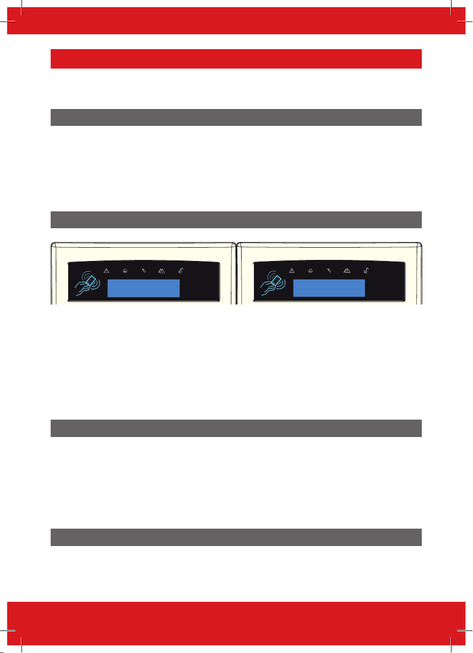
When in Engineer menu, the fault (=) LED will flash and a high pitched tone will be generated
regularly.
Exiting The Engineer Menu
On completion of programming, the system can be returned back to unset mode by either scrolling
to the ‘Exit Engineer Menu’ option, or by pressing a from any main menu option (represented in
capital letters).
6
Page 7

EURO 46 V10 Programming Manual
Accessing the Engineers Menu on any Keypad
It is possible to access the Engineer Menu on any keypad that is part of the system, even when
another keypad is already in the Engineers Menu. All other keypads will display ‘System Busy’ where
a keypad is in the Engineer Menu. To access the Engineer Menu on one of these keypads press b.
Saving The Programming
Any programming done in the Engineer or User mode will not be saved on the system until the
Engineer or User menu has been exited.
Writing Text on the keypad
On the EURO 46 V10 Panel it is possible to label the following:
• Inputs – 2 labels; Input Number and Location
• Area names
• Site name
• Keypad/Reader – 2 labels; Keypad number and location
• Input and output expander location descriptions
• User names
The control panel incorporates a predictive text feature, and works like so:
Enter ‘B’ and ‘Bedroom’ will be displayed. If the word that is required does not appear, then type the
word letter by letter.
To type a word, press the relevant button the appropriate number of times – e.g. for the letter ‘k’ press
5 two times, or for the letter ‘s’ press 7 four times. For punctuation marks, press the 1 button
multiple times until the desired character is shown.
Misc Button Typing
Button Text Function
a
c
b
d
[ ]
Makes the character into a capital
Clears letters / adds a space
Moves cursor left
Moves cursor right
Moves the cursor left and right
7
Page 8

EURO 46 V10 Programming Manual
Engineer Menu - Options
Inhibit Fire / HU (Hold Up)
This menu has a single sub-menu that simply allows you to toggle between ‘Yes [1]’ and ‘No [0]’, in
order to Inhibit a fire or Hold Up alarm while in engineer’s mode/menu. For example, you may wish to
inhibit smoke detectors while in the engineers menu so that you can work on them.
Set Date and Time?
All log entries and the system display include the date and time, so it is vital that the correct date and
time is programmed. This may be also programmed in the Master Manager mode.
PLEASE NOTE: Removing the mains power and disconnecting the battery will reset the time and
date information.
Change Year
For the year 2017, enter 17.
Change Month
For March, enter 03.
Change Day
For 31st, enter 31.
Change Hours
Use 24 hour clock format. For 8pm enter 20:00.
Change Minutes
For 7:30, enter 30.
DST (Summer Time) Adjust
If activated this option will automatically change one hour ahead and backward for the summer and
winter time.
Wireless Device Control?
This function learns or deletes all wireless inputs, bells and arming stations to the EURO 46 V10.
PLEASE NOTE: Keyfobs are learnt and programmed from the Master Manager Menu.
Control Inputs?
Learn Devices?
This menu starts the procedure of learning wireless inputs onto the Euro 46 V10.
Input
This menu chooses which input on the system is to be learned. ‘Learnt’ will be displayed if a device is
already learnt, or ‘Available’ if it is not.
Learning…
1. Open the wireless device.
2. Remove the plastic insulation to enable the battery.
3. If the device is not learnt, the GREEN and RED LEDs on the device will flash (alternating).
8
Page 9

EURO 46 V10 Programming Manual
4. Press and hold the ‘learn’ button on the device and all three LEDs start cycling through.
5. Release the ‘learn’ button. If successful, ‘Input Learnt’ will be displayed on the keypad and a
confirmation tone will be emitted.
6. If that input has already been learnt, ‘Input learnt already’ will be displayed.
To locate the learn button on each wireless peripheral, please refer to the installation manual provided
with the device.
Delete Devices?
Already learnt inputs may be deleted from this menu.
Delete All
To delete all wireless input devices, enter ‘2000’. ‘Please wait’ will be displayed while the EURO 46
V10 deletes all the learnt wireless inputs.
Choose Input to Delete
This option deletes only a specific wireless device learnt to an input. Any inputs that display ‘learnt’
can be deleted. ‘Please wait’ will be displayed while the Panel deletes the wireless device. Return to
this process to delete more devices.
Control Bells?
Learn Devices?
Entering this menu allows the learning of wireless bells onto the system.
Select Bell
Selects the bell on the system that is to be learnt. ‘Learnt’ will be displayed if a bell is already learnt,
or ‘Available’ will be displayed if not.
Learning…
1. Open the wireless bell.
2. Plug the battery connector into the battery terminal.
3. If a device is not learned, the GREEN and RED LEDs on the device will flash (alternating).
4. Press and hold the ‘Learn’ button on the device and all three LEDs start cycling around.
5. Release the ‘Learn’ button. If successful, ‘Bell Learnt’ will be displayed and a confirmation tone
on the panel will be emitted.
If a bell has already been learnt, ‘Bell learnt already’ will be displayed.
Delete Devices
Already learnt bells may be deleted by entering this menu.
Delete All
To delete all wireless bells enter ‘2000’. ‘Please wait’ will be displayed while the EURO 46 V10 deletes
them.
Select Bell to Delete
This option deletes only a specific wireless bell that is learnt. Any bells that display ‘learnt’ can
be deleted. ‘Please wait’ will be displayed while the Panel deletes the wireless bell. Return to this
process to delete more devices.
9
Page 10
EURO 46 V10 Programming Manual
Control Arming Stations?
Learn Devices?
Entering this menu allows the learning of wireless arming stations onto the system.
Select Arming Station
Selects the arming station on the system that is to be learnt. ‘Learnt’ will be displayed if an arming
station is already learnt, or ‘Available’ will be displayed if not.
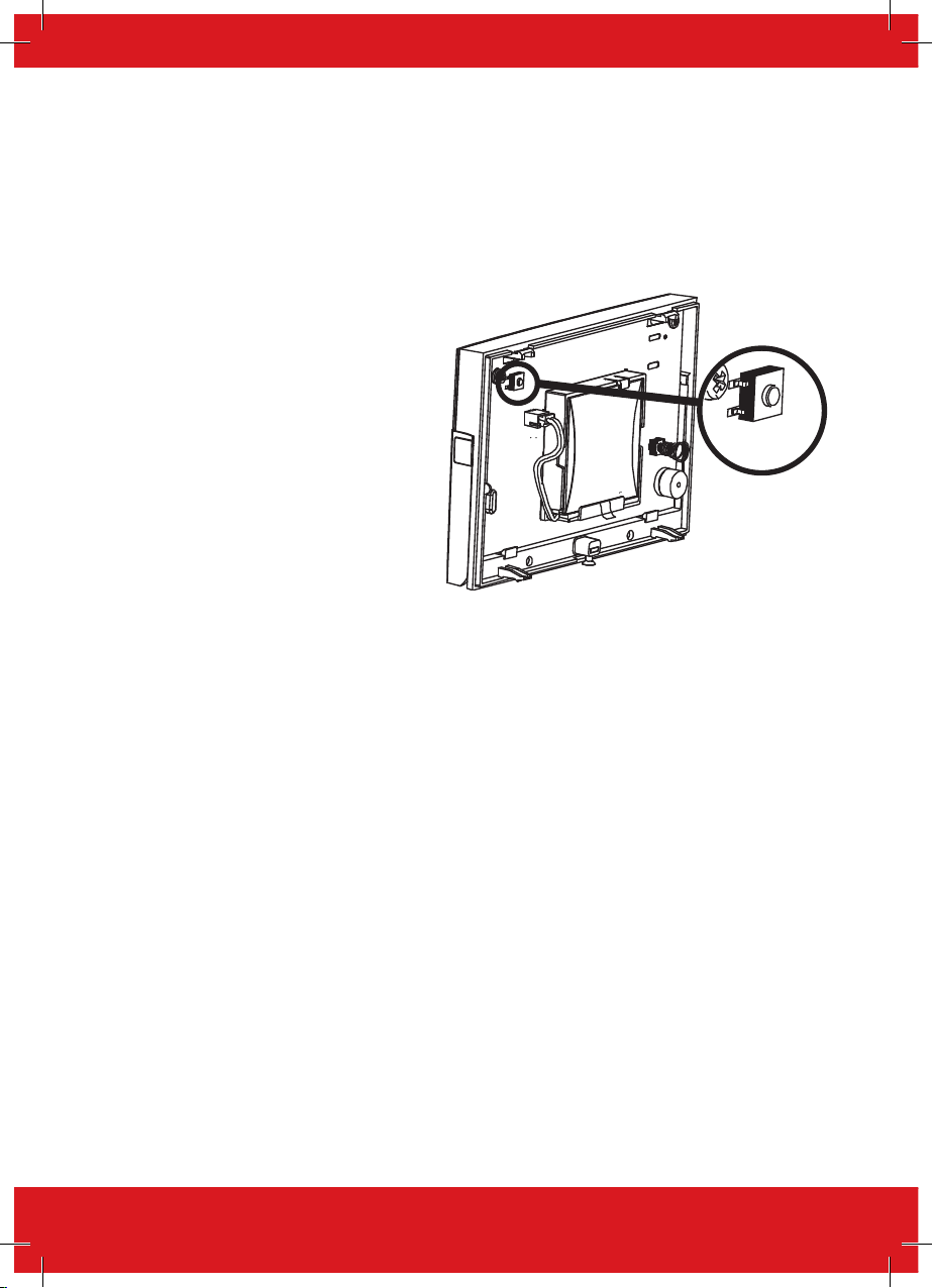
Select Arming Station Learning…
1. Open the Wireless Arming Station.
2. Plug the battery connector into the
battery terminal.
3. If a device is not learned, the GREEN
and RED LEDs on the device will flash
(alternating).
4. Press and hold the ‘LEARN’ button on
the device and all three LEDs will start
cycling around.
5. Release the ‘LEARN’ button. If
successful, ‘Arming Station Learnt’ will
be displayed and a confirmation tone on
the panel will be emitted. If an Arming
Station has already been learnt, ‘Arming
Station learnt already’ will be displayed.
Delete Devices
Arming Stations that have already been learnt, may be deleted by entering this menu.
LEARN
BUTTON
Delete All
To delete all Wireless Arming Stations enter ‘2000’ (this is the Panel Security Code). ‘Please wait’ will
be displayed while the EURO 46 V10 deletes them.
Select Arming Station to Delete
This option deletes only a specific Wireless Arming Station that is learnt. Any Arming Stations that
display ‘learnt’ can be deleted. ‘Please wait’ will be displayed while the EURO 46 V10 deletes the
Wireless Arming Station. Return to this process to delete more devices.
Learn Keyfobs Procedure
The key fobs are learnt and deleted from the Master Manager menu (Requires Wireless ZEM to be
setup and addressed).
Learn Key fobs?
1. Enter Master Manager menu (press the d key then enter code).
2. Scroll to the function ‘EDIT USERS?’.
3. Select ‘Add New User?’
4. Choose a user number to allocate the key fob to.
5. If a key fob, code or tag are not learnt, the space between the brackets will be empty.
6. If a key fob, code or tag are learnt, the brackets will show [******].
7. Press and hold any of the key fob buttons for five seconds, then release.
8. A confirmation tone will be emitted and ‘Select Button’ will be shown on the display.
10
Page 11

EURO 46 V10 Programming Manual
Proceed with the programming of actions to each key.
Delete/Change User (Key fobs)
1. Enter Master Manager menu (press the d Key then enter code).
2. Scroll to the function ‘EDIT USERS?’.
3. Select ‘Delete/Change User?’
4. Choose the key fob to delete = Between the brackets will show [******].
5. Press c = The brackets will be showing [ ] to confirm the deletion.
Program Key fob Buttons?
This menu is used to program the functionality of the buttons on the key fobs and is available in the
Engineer menu -> Wireless Device Control -> Program Key fob Buttons.
Choose User
Select the user key fob to program.
Select Button
The different buttons and button combinations that may be programmed are:
[1] Lock Button
[2] Unlock Button
[3] Button I
[4] Button II
[5] Lock + Unlock Buttons
[6] I + II Buttons
[7] Lock + I Buttons
[8] Unlock + II Buttons
Button Action
Options are: ‘show status’, ‘set area’, ‘unset area’ and ‘operate output’. Two key combinations may
also have ‘hold up’ assigned to them. ‘Set area’ features a sub-option to choose which area to set.
‘Operate output’ features a sub option to choose which output to trigger.
User Controls
If an action is programmed as ‘set area’, then the areas which the key fob will control can be selected
here.
PLEASE NOTE: Once all wireless inputs are learnt, an input type must be assigned to them, this is
programmed in ‘change inputs’.
11
Page 12

EURO 46 V10 Programming Manual
Change Inputs?
By default, all inputs are set to ‘unused’. Before programming, identify the input type required:
PLEASE NOTE: A full list of all input types can be found in ‘Appendix 1’.
Choose Input
Choose an input to program.
Input Type: Assign an input type to the chosen input. For a full list of input types, please refer to
‘Appendix 1’.
Input Areas:
Enter the areas (0,1,A,B,C,D) for input to operate in.
Input Areas (Any or All)
In some installations a ‘common’ area may be required. A common area is an area that only sets
when other specific areas become set. Example: An entry and exit reception area in a building may
only need to be set if both the offices and warehouse are set. If the office in Area A is set, but the
warehouse in Area B is still occupied, then the reception would still need to be inactive so people
would be able to leave the premises via the entry / exit reception route. One input can be allocated
to one or more areas. In this example the inputs located in the reception area will be programmed so
that the reception inputs will be in Area A and Area B, so these inputs must have the Input Areas set
as ‘ALL’ programmed.
Area A: Office - Inputs = 3, 4, 5
Area B: Warehouse - Inputs = 6, 7, 8
Reception inputs – 1 and 2 are programmed into both Areas A and B, with both inputs configured as
‘ALL’. The Reception Area inputs will now only become active if both Area A and Area B are both set.
Input Attributes
Attribute Operation for both wired and wireless inputs
Chime When enabled the system loudspeaker(s) will ‘chime’ when an input is triggered while the alarm panel is
Omittable Enables the input to be manually omitted (disabled) from the setting procedure. To omit inputs, there is a
Double Knock If enabled, if this input is triggered twice within the pre-programmed time window or if the input remains active
Dual Trip The control panel will only generate an alarm if this input, and another like-programmed input (with adjacent
Normally Open
Walk Test If enabled, a walk test will need to be done on the particular input before the system can be set.
Monitor Activity This option is used in conjunction with NAT (none activity timer) in the ‘CHANGE TIMERS’ menu. When
Special Log Forces a log entry when the input is opened or closed, even when an alarm does not result. May be selected
unset. Chime can be set to ‘single’ (sounding once) or ‘follow’ (sounding while the door is left open). NOTE:
The chime can be turned on or off in unset mode by pressing [c] when all Entry Delay inputs are closed.
function in the Master Manager menu called ‘OMIT INPUTS’.
for that period, an alarm will be generated. The double knock option does not work on ‘Follow’ input type.
number), are in alarm condition at the same time. Either input in alarm condition will prevent the system from
setting.
#
Enables the system to respond correctly when detectors of ‘normally open’ configuration are wired to the
system. Alternatively converts input types which default to ‘normally open’ (such as Push to set) to operate
with normally closed devices.
enabled this option will trigger an output once the NAT time has elapsed. An example scenario in which it
might be used: A security guard who is obligated to walk a set route every hour – could be monitored by a
detector (with this input attribute enabled). Failure to walk the route would activate an output, perhaps to a
communications device, siren or light.
to apply when a system is set, when unset, or always.
12
Page 13

EURO 46 V10 Programming Manual
Attribute Operation for both wired and wireless inputs
Confirm Group If inputs are selected into the same confirm group, each input will only generate an unconfirmed alarm (and
#
The use of this input attribute will make the system unable to comply to EN50131-1 Security Grade 2 or 3.
will not generate a confirmed activation). This is useful when two or more shock sensors are being activated
by the same event. If a confirm group is selected as ‘00’, the inputs are not part of any group.
Input Description
Two text labels can be associated to each input:
Enter Name:
This is commonly used to write the input name/number, such as: input 1, input 2. This label will show
the event log and following alarms reported in the SMS alarms as a reference point.
Enter Location:
This is commonly used to write the location of the input, such as: Input Name = Input 1; Input
Location = Living Room. In case there has been a tamper alarm on the input the SMS or APP
notification will show: ‘Input 1, Living Room, Tamper Alarm’. The display will be show: 1-Living Room,
Tamper on Input. Meaning: Tamper alarm on input 1, which is the Living Room.
Manually Omitting Inputs
Method 1: (EN50131-1 Grade 2 and 3 compliant).
While the system is setting, press the key to omit inputs.
Method 2: (Only used to omit 24hr inputs).
Enter Master Manager menu -> ‘Omit Inputs’ to omit the inputs required.
PLEASE NOTE: The input attribute ‘Omittable’ must be enabled on each input so that the user has
the ability to omit them.
Choose Mode?
If any wired inputs are used, the resistance, EOL mode and response time can be programmed.
PLEASE NOTE: Alarm 4K7, Tamper 2K2 must be selected if wiring double pole to any input.
EOL Range (End of Line Range)
‘EOL Range’ programs the panel to operate with different resistor values
[0] Alarm: 1K, Tamper: 1K. [1] Alarm: 4K7, Tamper: 2K2.
[2] Alarm: 4K7, Tamper: 4K7. [3] Wide range.
EOL mode (Double End of Line (DEOL) or Single End of Line (SEOL))
‘EOL Mode’ programs the panel to operate as:
[0] SR - Single End of Line (SEOL). [1] DR - Double End of Line (DEOL).
Input Response Time
‘Input Response Time’ programs the time that an input must to open before the control panel
generates an alarm.
[01]-[30] = 100ms to 3000ms
PLEASE NOTE: Settings above (>) 400ms do not comply with PD6662/EN50131.
13
Page 14

EURO 46 V10 Programming Manual
Choose Mode Programming
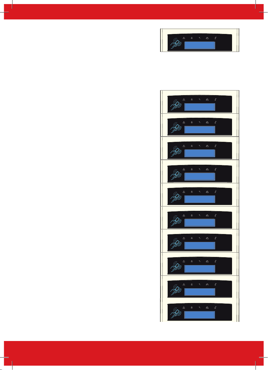
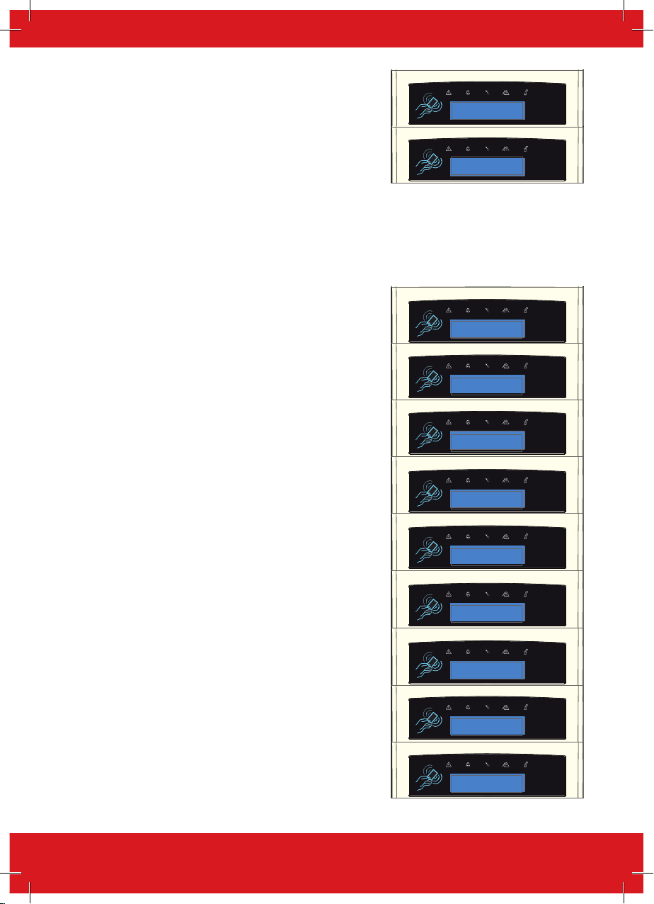
1. Press b or to scroll to ‘CHOOSE MODE’. Press
.
CHOOSE MODE?
2. Press b or d to select the ‘EOL Range’ for all
wired inputs*, Then press .
EOL Range
4K7/2K2 [1]
3. Press b or d to select the ‘EOL Mode’ for all wired
inputs. Then press .
EOL MODE
DR [1]
4. Press b or d to select the ‘Input Response’ for
all wired inputs*. Press to return to the Engineer
Menu.
Input Response
100ms [01]
Install ZEMs?
Any Zone Expander Modules (ZEMs) installed on the EURO system must be enabled using the
‘INSTALL ZEM’ menu function.
ZEM Address
[0] ZEM Address 0 (Inputs 9-16) [1] ZEM Address 1 (Inputs 17-24)
[2] ZEM Address 2 (Inputs 25-32) [3] ZEM Address 3 (Inputs 33-40)
[4] ZEM Address 4 (Inputs 41-48) [5] ZEM Address 5 (Inputs 49-56)
[6] ZEM Address 6 (Inputs 57-64) [7] ZEM Address 7 (Inputs 65-72)
ZEM Installed
[0] No [1] ZEM8 / EURO37R [2] ZEM32-WE
Enter Location
The text entered here will be displayed on the LCD display if a fault occurs on the ZEM, so the ZEM
can be easily located or referenced.
Install ZEMs Programming
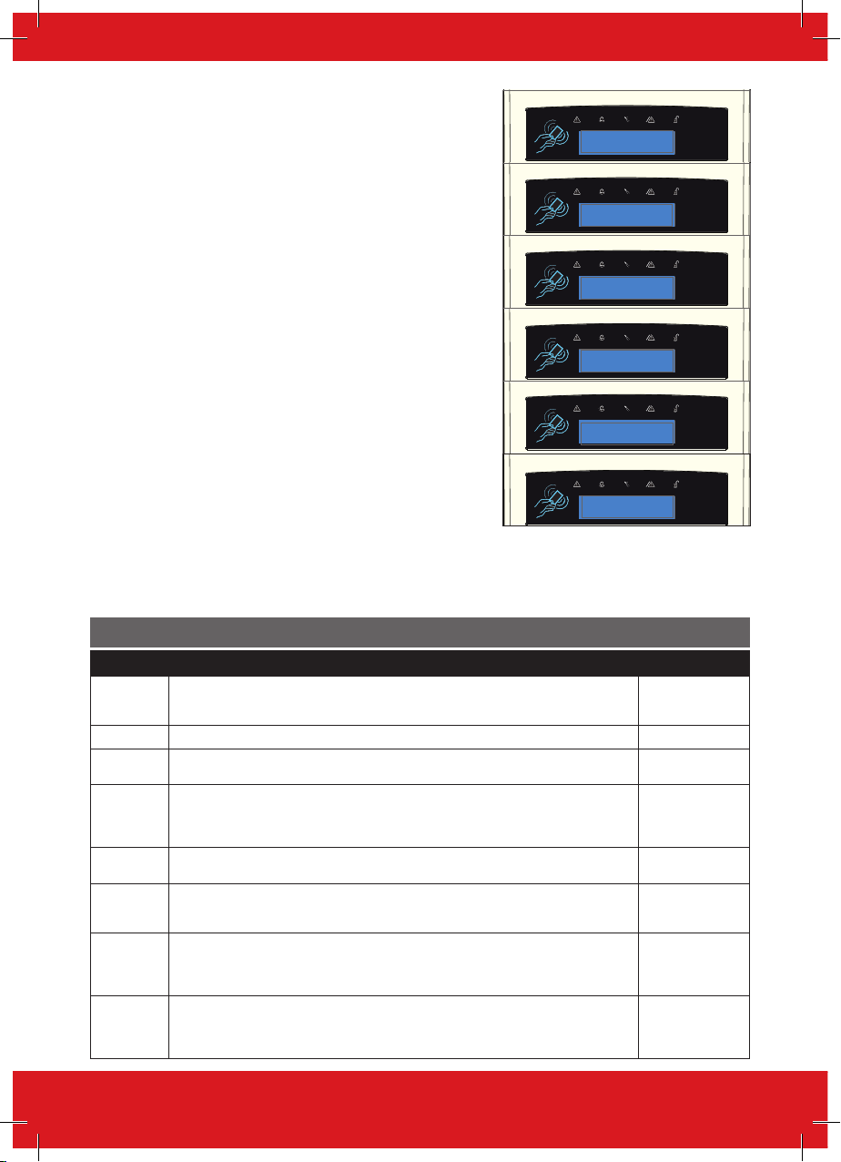
1. Press b or to scroll to ‘INSTALL ZEMs?’.Press
.
INSTALL ZEMs?
2. Press b or d to select the ‘ZEM Address’ . Press
.
ZEM Address
[0]
3. Press b or d to select either ‘ZEM8/EURO37R’,
‘ZEM32-WE’ or ‘No’ to ‘ZEM Installed’. Press .
ZEM Installed
No [0]
4. Enter the location of the ZEM. Press to return to
ZEM addressing.
Enter Location
_
14
Page 15

EURO 46 V10 Programming Manual
5. Press to return to the Engineers menu.
PLEASE NOTE: If using wireless bells, Wireless Arming Stations or key fobs, the wireless ZEM has to
be addressed as 00.
Change Outputs?
This option enables the programming of the outputs on the EURO 46 V10 and any devices that are
connected to it. For a full list of output types please refer to ‘Appendix 2’.
Endstation Outputs?
These are the outputs on the control panel itself: BELL O/P, STB O/P, PGM O/P, XPGM1 O/P, XPGM2
O/P, and ATE PINS 1-9. All of these are programmable but at default the BELL and STB are allocated
to follow the alarm in any area as bell and strobe.
ZEM Outputs?
These are the outputs that are located in the ZEM8+ or ZEM8+PSU input expander modules, if used,
there are four PGMs located on each of these modules.
Wireless Bells?
These are the wireless bell outputs of the ZEM32-WE if installed. There are two outputs – BELL O/P
and STB O/P both of which are programmable.
Output Module Outputs?
This option enables the addition of a wired output module to the Control Panel, as well as
programming of the PGM options for the outputs on the module.
Keypad Outputs?
Allows the programming of the PGM options for the outputs located on the wired keypads.
Reader Outputs?
Allows the programming of the PGM options for the outputs located on the wired readers.
User Outputs?
These outputs are used for creating automation control for devices. The user can control them
remotely from the user menu on the keypad or via the HomeControl+ smart phone APP. The
automated user outputs can be programmed (either latched or timed).
Polarity of the PGMs: The polarity of the outputs are normally switched negative, i.e. normal status
OFF = 12VDC and in active status ON = 0VDC.
PLEASE NOTE: The PGM Outputs polarity cannot be inverted.
Assign Keypads and Readers?
Ensure that all keypads and readers are addressed correctly (at the device) before enabling and
addressing them in this function. To address at the device please refer to the installation reference
manual.
PLEASE NOTE: At least one keypad/reader should have the ability to unset any areas programmed.
Address /Arming Station Address
Addresses from 00 - 05 allow allocation of external wired readers or keypads, and 06 - 09 are for
Wireless Arming Stations.
15
Page 16

EURO 46 V10 Programming Manual
Type
The device types that are available will depend upon the selected address:
LCD keypads [0], Readers [1] Not Used [2], Arming Stat [3]
Reader is
If a reader is installed, the following options can be assigned to the reader:
[0] Set Point: Reader used for setting and unsetting.
[1] Ward Control: A reader can be used to create wards. For example: A keypad may control a full
area, but within that area you may wish to control certain inputs only.
[2] Access Control: If an access control system is installed then the reader must be programmed as
this type. The lock open time and door open time can be programmed (in seconds).
[3] Unset Only: Select this type if the reader is to be used as an unset device only.
[4] Entry Control: This option is used when the reader is used to lock/unlock doors and also is to be
used to set and unset the system. This option is used in conjunction with ‘tag opens doors’ which can
be found in ‘Site Options’ which is a sub-menu within ‘SYSTEM OPTIONS?’ The lock open time and
door open time can be programmed (in seconds).
Programming Keypads: Assign Keypads/Readers
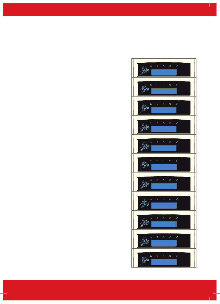
1. Press b or to scroll to ‘ASSIGN KEYPADS/
READERS’. Press .
ASSIGN KEYPADS/
READERS?
2. Press b or d to select the address. Press .
Address
[1]
3. ‘Type’ will be displayed. Press to select
‘Keypad’. Press
Type
Keypad [0]
4. ‘Set Point Sets’ will be displayed. Select the area(s).
Press .
5. ‘Set Point Unsets’ will be displayed. Select the area(s).
Press .
6. ‘Set Point In’ will be displayed. Enter the Area in which
the keypad is situated and press .
7. ‘Set Point Description’ will be displayed. Press to
enter the name and location if required.
8. ‘Enter Name’ will be displayed. Enter the name of the
keypad and press .
16
Set Point Sets
[01ABCD]
Set Point Unsets
[01ABCD]
Set Point In
[01ABCD]
Set Point
Description?
Enter Name
Device 01
Page 17
EURO 46 V10 Programming Manual
9. ‘Enter Location’ will be displayed. Enter the location of
the keypad and press .
Enter Location
_
10. Press b or d to select another device address
to program (0-9) or press the key to return to the
Engineer Menu.
Programming Readers for Set Point or Unset Only: Assign Keypads/Readers
1. Press b or to scroll to ‘ASSIGN KEYPADS/
READERS’. Press .
ASSIGN KEYPADS/
READERS?
2. Press b or d to select the address. Press .
Address
[1]
3. ‘Type’ will be displayed. Press 1 to select
‘Reader’. Press
Type
Keypad [0]
4. ‘Reader is’ will be displayed. Press for ‘Set Point’ or
press 1 for ‘Unset Only’ Press .
Reader is
Set Point [0]
5. ‘Set Point Sets’ will be displayed. Select the area(s).
Press .
Set Point Sets
[01ABCD]
6. ‘Set Point Unsets’ will be displayed. Select the area(s).
Press .
7. ‘Set Point In’ will be displayed. Enter the area in which
the keypad is situated and press .
8. ‘Set Point Description’ will be displayed. Press to
enter the name and location if required.
9. ‘Enter Name’ will be displayed. Enter the name of the
keypad and press .
10. ‘Enter Location’ will be displayed. Enter the location of
the keypad and press .
Set Point Unsets
[01ABCD]
Set Point In
[01ABCD]
Set Point
Description?
Enter Name
Device 01
Enter Location
_
17
Page 18
EURO 46 V10 Programming Manual
11. Press b or d to select another device address
to program (1-7) or press the key to return to the
Engineer Menu.
Programming Readers for Entry Control or Access Control: Assign Keypads/Readers
1. Press b or to scroll to ‘ASSIGN KEYPADS/
READERS’. Press .
ASSIGN KEYPADS/
READERS?
2. Press b or d to select the address. Press .
Address
[1]
3. ‘Type’ will be displayed. Press 1 to select the
reader. Press
Type
Keypad [0]
4. ‘Reader is’ will be displayed. Press for ‘Access
Control’ or press for ‘Entry Control’ (as shown in
example) & Press .
Reader is
Set Point [0]
5. ‘Set Point Sets’ will be displayed. Select the area(s).
Press .
Set Point Sets
[01ABCD]
6. ‘Set Point Unsets’ will be displayed. Select the area(s).
Press .
Set Point Unsets
[01ABCD]
7. ‘Set Point In’ will be displayed. Enter the Area in which
the keypad is situated and press .
8. ‘Lock Open Time’ will be displayed. Enter the Lock Open
Time in seconds and press . (Max 255 seconds).
9. ‘Door Open Time’ will be displayed. Enter the Door Open
Time in seconds and press . (Max 255 seconds).
10. ‘Door Contact No.’ will be displayed. Press to enter
a number and then press again.
11. ‘Access Control Description’ will be displayed. Press
.
18
Set Point In
[01ABCD]
Lock Open Time
Seconds [005]
Door Open Time
Seconds [010]
Set Point In
[01ABCD]
Set Point
Description?
Page 19
EURO 46 V10 Programming Manual
12. ‘Enter Name’ will be displayed. Enter the name of the
keypad and press .
13. ‘Enter Location’ will be displayed. Enter the location of
the keypad and press .
14. Press b or d to select another device address
to program (1-9) or press the key to return to the
Engineer Menu.
Programming Wireless Arming Stations: Assign Keypads/Readers
1. Press b or to scroll to ‘ASSIGN KEYPADS/
READERS’. Press .
2. Press b or d to select from addresses 6 - 9. Press
.
3. ‘Type’ will be fixed as [3] (Arming Station) Press
4. ‘Options?’ will be displayed. Press .
Enter Name
Device 01
Enter Location
_
ASSIGN KEYPADS /
READERS?
Arming Address 1
Station 01 [6]
Type
Arming Stat [3]
Options?
5. ‘Tag Reader Enable’ will be displayed. This option enables
or disables the Tag Reader on the wireless Arming Station.
Disabling it will conserve battery power. Select then - Press
.
6. ‘Auto Wakeup’ will be displayed. This option wakes the tag
reader from sleep mode during the entry process/walking the
entry route. Select to enable or disable then - Press .
7. ‘Supervision’ will be displayed. Radio supervision & battery
monitoring improve security, but can be disabled to save
battery power. Select to enable or disable and then - Press .
8. ‘Back Light’ will be displayed. When enabled, the backlight will illuminate for 5 seconds after any key press.
Select to enable or disable and then - Press .
9. ‘Entry/Exit Sound’ will be displayed. This enables or disables
the entry and exit sounds from the small piezo in the Arming
Station. Select to enable or disable, then - Press .
Tag Read Enable
No [0]
Auto Wakeup
No [0]
Supervision
No [0]
Backlight
No [0]
Entry/Exit Sound
No [0]
19
Page 20
EURO 46 V10 Programming Manual
10. ‘Set Point Sets’ will be displayed. Select the area(s).
Press .
11. ‘Set Point Unsets’ will be displayed. Select the area(s).
Press .
12. ‘Set Point In’ will be displayed. Enter the Area in which
the Arming Station is situated and press .
13. ‘Set Point Description’ will be displayed. Press to
enter the name and location if required.
14. ‘Enter Name’ will be displayed. Enter the name of the
wireless Arming Station and press .
15. ‘Enter Location’ will be displayed. Enter the location of
the wireless Arming Station and press .
16. Press b or d to select another device address
to program 7 - 9 or press the key to return to the
Engineer menu.
Set Points Sets
[01ABCD]
Set Point Unsets
[01ABCD]
Set Point In
[01ABCD]
Set Point
Description?
Enter Name
Station 01
Enter Location
_
Change Timers?
Timers Description Options
Entry Time
(01ABCD)
Entry Time 2 Same as above therefore allowing for different timers on 2 entry routes. 0-255 seconds
Exit Time
(01ABCD)
APP Exit
Time
Siren Time
(01ABCD)
Siren Delay
Confirm
Time
HU Confirm
Time
Programs the entry time for each area.
PLEASE NOTE: Ensure that the timer is no longer than 45 seconds in order to comply with
EN50131-1.
Programs the exit time for each area. 0-255 seconds
Programs the exit time for each area that is applied when the area is set using the
HomeControl+ Android or iOS App.
PLEASE NOTE: This time must be set at 30 seconds or more to comply with
PD6662:2010+IA:2015.
Program the length of time an external sounder will be audible for. 2-15 minutes
The delay after the intruder alarm before bell activates.
PLEASE NOTE: Not valid within three minutes of final set, or after entry time started. If ‘Silent
1st Alarm’ is selected in alarm responses the delay commences at confirmed alarm.
Time period during which a second activation must occur to qualify as a ‘sequentially
confirmed’ alarm.
PLEASE NOTE: BS8243 specifies a confirm time between 30 and 60 minutes. This can also
be used in conjunction with testing an omit signal.
Time period during which a second activation on a hold alarm must occur to qualify as a
‘sequentially confirmed’ alarm.
PLEASE NOTE: BS8243 specifies a confirm time between eight and 20 hours. This can also
be used in conjunction with testing an omit signal.
20
0-255 seconds
0-199 seconds
0-20 minutes
1–99 minutes
8 – 20 hours
Page 21

EURO 46 V10 Programming Manual
Timers Description Options
Strobe Time
Re-Arm No.
AC Signal
Delay
Settle The time between the set procedure completing and the area arming. 0-255 seconds
Double
Knock
Pre-Alarm
Comms Fault
Delay
Set Fail
Guard Code
Alarm
Fire Siren
Time
Set Fail
Warning
Input NAT
Days
Input NAT
Hours
Wireless
Supervision
Time
Wireless
Jamming
Time
Service Time
The duration of time the strobe output remains live after the bell time ends
PLEASE NOTE: ‘99’ means endless.
The number of times the system re-arms after the confirmation time ends. Re-arm number
applies to each area and does not affect emergency alarms (‘9’ = ‘always re-arm’).
The time delay before the mains failure or technical alarm is notified. System changeover to
battery supply and associated visual alert indication is always immediate.
Some ATE impose a set delay in notifying a mains fail. This should be taken into account
when setting this timer.
PLEASE NOTE: Setting the timer to ‘250’ will never send a signal.
The length of the time which two activations of an input must be received from any which
have the ‘Double Knock’ attribute set to ‘Yes’.
Delays ‘Intruder’ output signals if the entry time has started.
PLEASE NOTE: Pre-alarm time must be set for at least 30 seconds to comply with PD6662.
Duration that the panel must detect a signal path failure.
PLEASE NOTE: In the case of devices connected via the ATE pins, this time is additional to
that already applied by the ATE.
The time after which the ‘Set Fail’ operation will be invoked if the exit procedure is not
completed.
Minimum time an alarm must have existed before a Guard Code will be accepted to unset. 0-10 minutes
The cut off time for the fire alarm
PLEASE NOTE: ‘99’ means endless.
The time which a set fail warning will be present. 0–99 minutes
This ‘Non-activity Timer’ (NAT) works in conjunction with the input attribute ‘Monitor Activity’
and defines the time after which the ‘Zone Activity Fl’ output will be triggered when ‘Monitor
Activity’ is enabled for an associated input.
Used in conjunction with ‘Input NAT Days’ to give a total time defined in days and hours
combined (e.g. 0 days, 1 hour or 14 days, 23 hours etc.)
This option is only applicable if wireless devices are installed. This is the time period which
the panel must receive a signal from each of the wireless devices.
PLEASE NOTE: This must be programmed to two hours or less for compliance to EN50131.
This option is only applicable if wireless devices are installed. This governs the length of time
a wireless input’s signals can be ‘jammed’ before the panel reports a fault.
PLEASE NOTE: This must be programmed to 1 - 30 seconds for compliance to EN50131.
This is a timer set to warn the user that a service on their alarm system is due. An Engineer
Code is needed to clear the message.
0-99 minutes
0-9
0-250 minutes
0-75 seconds
0–255 seconds
0–250 minutes
5–255 seconds
1–99 minutes
0-14 days
0-23 hours
0-99 hours
0-100 seconds
0-734 days
21
Page 22

EURO 46 V10 Programming Manual
Codes And Users?
Five Digit PINs?
Set this option to ‘Yes’ to allow the use of 5 digit and 6 digit codes (This will disable codes below 5
digits in length). Set this to ‘No’ if you would prefer to use codes below 5 digits in length.
Delete Users And Fobs?
This function deletes all the user codes (or tags/fobs assigned to a user) from the system.
Change Duress/Guard Codes?
This function changes the Engineer code, the Master Manager code and adds/changes/deletes any
Duress or Guard codes.
PLEASE NOTE: User codes, proximity tags and key fobs can only be changed in the Master
Manager Menu, however users can change their own codes (if a user code has been set up).
Duress Code Types
Duress Code: If the Control Panel is unset using a ‘Duress Code’, a silent ‘Duress’ or ‘Hold Up’ signal
is sent.
PLEASE NOTE: ACPO policy prevents use of Duress codes for police call purposes.
Guard: A ‘Guard Code’ can be used to unset the control panel only after the ‘Guard Code Alarm’ time
has expired. The code will set a system and an output type (00058 Guard Code) will activate when
this code is used.
Dial Out: A dial code is used to force the panel to dial the UDL software while in ‘Day Mode’
Change Master Manager Code
The Master Manager code can be 4, 5 or 6 digits long, or can be assigned to a proximity tag. It may
also have the following functions:
User Areas: (01ABCD) The areas to which the code applies.
User Set Options: [0] Unset/Set. [1] Unset Only. [2] Set Only. [3] None (menu access only).
Flexi Set: If enabled the default area the device is assigned to will set. If disabled the default area will
be shown on the display and from here other areas can be selected.
Wards/Access: This will only be displayed if an Entry Control or Access Control reader is installed
on the system. If the address of the Entry Control or Access Control device is entered here, then the
code will be assigned to that reader only.
User Name: Enter a name for the user or group that use this code.
Change Engineer Code
The Engineer code can be 4, 5 or 6 digits long.
Change Codes Programming
1. Press b or to scroll to ‘CODES AND USERS?’.
Press .
2. ‘5 digit PINS?’ will now be displayed. Press 1 for ‘Yes’
or for ‘No’ then press to move on.
22
CODES AND USERS?
5 digit PINs?
Yes [1]
Page 23

EURO 46 V10 Programming Manual
3. The LCD will now display ‘Delete Users And Fobs?’. Press
and ‘Are you Sure?’ will be asked. Press to delete
all users or to go back.
PLEASE NOTE: This is not reversible.
Change Duress
Codes?
4. ‘Change Duress Codes’ will be displayed. Press to
add any Duress, Guard or Dial out codes or press .
Change Duress
Codes?
5. ‘Change Master Manager Code’ will be displayed. Press
to change the Master Manager code or press .
Change Master
Manager Code?
6. ‘Change Engineer Code’ will be displayed. Press
to change the Engineer code or press to return to
the Engineer menu.
Change Engineer
Code?
Volume Control?
The Volume Control function applies to both the main sounder, the on-board keypad or any additional
keypads.
Area A,B,C,D,0,1 Entry Tone Volume
0=Completely Silent, 1=Silent, but beeps when the system is set. 2-5 keypad 6&7 = Main Sounder
Area A,B,C,D,0,1 Exit Tone Volume
0=Completely Silent, 1=Silent, but beeps when the system is set. 2-5 keypad 6&7 = Main Sounder
Area A,B,C,D,0,1 APP Exit Tone Volume
0=Completely Silent, 1=Silent, but beeps when the system is set. 2-5 keypad 6&7 = Main Sounder
Alarm Volume
0=Completely Silent, 1=Silent, but beeps when the system is set. 2-5 keypad 6&7 = Main Sounder
Fire Alarm Volume
0=Completely Silent, 1=Silent, but beeps when the system is set. 2-5 keypad 6&7 = Main Sounder
Tamper Alarm Volume
0=Completely Silent, 1=Silent, but beeps when the system is set. 2-5 keypad 6&7 = Main Sounder
Day Alarm Volume
0=Completely Silent, 1=Silent, but beeps when the system is set. 2-5 keypad 6&7 = Main Sounder
Chime Volume
0=Completely Silent, 1=Silent, but beeps when the system is set. 2-5 keypad 6&7 = Main Sounder
Code Stops Sound
If this function is enabled, then once an alarm has been generated (even if the code is not
programmed for that area) the alarm will be silenced, and a ‘Misoperation (Abort) signal’ will be sent.
The area will remain set until a code or tag is presented that is assigned to that area.
23
Page 24

EURO 46 V10 Programming Manual
Entry/Exit Keypads Only
If this function is disabled, any entry and exit tones will be heard through the main sounder. If
enabled, the entry and exit tones will only be heard through the keypad speaker.
Alert Kps Only
If this function is enabled, any ‘Alert’ tones will be heard on the keypad only and not the main
sounder. If disabled, the alert tones will heard through both.
Silent Technical Alert
If this function is enabled then any technical alerts will be silenced, such as: line fault, ARC call fail.
System Options?
Site Options
Option Description
Set With Fault
Set With Tamper
Set With ATS Fault
Set Ward Tech Fault If ‘Yes’ a ward can set even if mains, battery, Comms, or other system faults are present.
Set Fail = Alarm
Do Battery Load Test If ‘Yes’ the system will perform a full load test of the battery at 7:00am each day.
Strobe/Squawk at Set
Re-Arm Omits
Use Level Set
Confirmed When
Autoset Force If ‘Yes’ when auto-set is in use the panel will still set even if an input is open at the time.
Restrict PIN Use
Simple Set
Intelligent Set
Invert ATE Outputs If ‘Yes’ the outputs are positive removed. If ‘No’ the outputs are positive applied.
If ‘Yes’, the panel will set regardless of the following faults being present:
Device fail, mains fail, battery fault, fuse fault, SMS failure, relay sirens 1&2 or relay strobe faults.
If ‘Yes’, the panel will set regardless of the following tamper faults being present:
Case tamper and any system tampers.
If ‘Yes’, the panel will set regardless of the following ATS faults being present: Telecom line fail,
modem fail, STU/ATE line fault, STU/ATE one path fail, Digi dial fail, or STU/ATE Comms fail.
If ‘Yes’ a graduated alarm will be generated when the ‘Set Fail’ timer expires. If an exit procedure is
still incomplete then the set fail output will trigger too. If ‘No’ the ‘Exit Time’ will continue until the exit
door is closed and the system will return to unset mode at the end of the ‘Set Fail Warning’ time if
programmed.
If set to 'Strobe', any output programmed as ‘Strobe any’ will activate for five seconds after the
control panel has fully set. If ‘Squawk’ is selected, any output programmed as ‘Siren any’ will activate
for five seconds after the panel has set. Finally if set to 'Both' any outputs programmed as ‘Strobe
any’ or ‘Siren any’ will activate for five seconds after the panel has fully set.
PLEASE NOTE: If this function is enabled, a potential security risk could be in view for intruders to
see.
If ‘Yes’ when the panel rearms at the end of the confirmation time, this function will force an input
(not a system tamper) causing the unconfirmed alarm to be omitted, whether it’s still in fault or not.
If ‘Yes’, the system becomes ‘level set’ (having one area set only at any one time). If ‘No’: The system
becomes an ‘area’ system (fully independent areas).
Final Set: Confirmed signal only available after the system is set.
Exit Starts: Confirmed signal available after the exit time has started.
PLEASE NOTE: ‘Exit starts’ is not compliant with BS8243.
PLEASE NOTE: ‘Exit Starts’ must be selected in order for it to be entered in the logs.
If ‘Yes’ the system prevents a pin code being entered on the ‘Entry Time’, but allows the system to
be silenced and unset once in alarm.
PLEASE NOTE: Enable when BS8243 option 6.4.5 is in use.
If ‘Yes’, the control panel allows a user to set the system ‘quickly’ by pressing and then the
Area (0, 1, A, B, C or D).
PLEASE NOTE: This must not be enabled when BS8243 option 6.4.5 is in use.
When enabled, the panel will set in level set ‘B’ (the user code used must have level sets A and B
assigned), but if a final exit input is activated (such as a front door) on level set ‘A’, the panel will
automatically switch to setting level set ‘A’. If no input is activated, the panel will just set level set ‘B’.
24
Page 25

EURO 46 V10 Programming Manual
Option Description
If ‘Yes’, this will automatically prioritise the exit modes for each area:
(0 = Timed, 1 = Final Door, 2 = Timed/Final Door, 3 = PTS). This option is only relevant when Final
Common Lobby?
Flexi Unset
2 Key HU
External ATE Inputs
Tag Opens Doors
Set With Polling Fault
Fob Unset Entry
Wireless Bell Supervision
Download if Set
UDL/Cloud Priority
Door option is used on a system with different areas using a common lobby.
EXAMPLE: If Area C is selected as the ‘Final Door’ setting mode and the rest of the areas are
selected as ‘Timed’, then because ‘Final Door’ is higher priority, the users of every individual area
must follow the ‘Final Door’ route to the exit - making this door a ‘common for all areas’. If set to ‘NO’
the exit modes will be individually programmable to each area.
When enabled, this setting will allow users to select which areas they unset (from the areas that they
have been permitted to unset).
If the 1 and 7 keys are pressed and held together for a period of time (programmed in the
keypad menu), a 'Hold Up' will occur.
If ‘NONE’, the keys are disabled. If ‘SILENT’, a ‘Silent Hold Up’ will be signalled. If ‘Bells Only’,
any external sounder will activate but NO signals will be sent. If ‘BOTH’, any external sounder will
activate and a signal will be sent using the DIGI-GPRS.
Permits selection of inputs to ATE pins to suit ‘ATE’ (including RedCare Reset), ‘DigiCom’ (including
Telback), ‘Relay Interface Monitoring’ or ‘Not Used’.
NOTE: This option must be set to ‘ATE’ or ‘Digi’ in order for Line Fault, etc. monitoring to function.
This option is NOT required for use with the digi-modem.
This function is only used in conjunction with a reader being programmed as 'Entry Control' in
'ASSIGN KEYPADS/READERS'.
If ‘YES’ the ‘Entry Control’ readers will control the setting/unsetting and the doors. If ‘NO’ the Entry
Control readers will control the setting/unsetting only.
If ‘YES’ the control panel will still set even if there is a wireless polling fault. The panel will not display
a wireless polling fault.
If ‘NO’ the user will not be able to set the panel with a polling fault. The panel will display a fault and
the setting procedure will be stopped.
If 'YES' any wireless key fobs learnt will only be able to unset the panel once the entry timer has
been activated. If ‘NO’ any wireless key fobs learnt will always be able to set and unset the Control
Panel.
If 'YES' then the wireless external sounder will go into alarm if it can no longer communicate with the
control panel / Wireless ZEM.
If 'YES' any upload/download procedures will be possible on the InSite software regardless of the
set/unset status of the Control Panel.
If this is set to ‘high’, the Cloud signalling will take priority over ARC signalling events (may delay
them slightly) to maintain a smooth cloud connection. If the system is graded (defaulted with clean
start code 2002 for Grade 2 or 2000 for Grade 3), then this setting will default to ‘low’ so that Cloud
connections cannot delay ARC signalling events.
System Displays
Area Texts (01ABCD)
Full Area Text The text that is displayed when all areas are set.
Sign On Message This is the message that is displayed in day mode.
Display When Set
Display Alarms
Display HUs
The text can be programmed for each area; such as ‘Area 0’ you may want to be ‘Full House Set’.
PLEASE NOTE: A maximum of 16 characters is allowed.
If ‘Yes’, the keypad display will show the area text when that particular area is set.
PLEASE NOTE: This must be programmed as ‘No’ to ensure compliance with EN 50131.
If ‘Yes’, then the keypad display will show all alarms, without requiring a user to enter their code or
present their tag.
PLEASE NOTE: This must be programmed as ‘No’ to ensure compliance with EN 50131.
If 'Yes’, then the keypad display will show any HU alarms that have occurred without requiring the
user to enter their code or tag.
PLEASE NOTE: This must be programmed as ‘No’ to ensure compliance with EN 50131.
25
Page 26

EURO 46 V10 Programming Manual
Display Inputs
If 'Yes’, then the keypad display will show any inputs that are activated in unset mode.
PLEASE NOTE: This must be programmed as ‘No’ to ensure compliance with EN 50131.
Exit Modes
Exit Mode Description
[0] Timed
[1] Final Door
[2] Timed/Final
[3] Push To Set
Providing that all inputs are closed, the system will only set when the programmed 'Exit Time' has
expired.
The system will only set when an input programmed as 'Final Exit 1' or 'Final Exit 2' opens and
closes.
This function follows the 'timed' operation, except that the timer will be overridden if an ‘Final Exit’
input is opened and closed before the timer expires.
The system will only set when a 'Push to Set' button has been pressed. This function will override the
programmed 'Exit Time'. The button can be used as a door bell when the ‘Chime’ input attribute is
enabled.
PLEASE NOTE: If the setting has not been completed within the programmed exit time, it is possible
to generate an alarm or return to unset mode. These parameters are defined in ‘Change Timers’ and
the sub-menu ‘Site Options’ located in ‘System Options’.
Review Logs?
There are two logs available on the system; panel and access control. Each log displays the most
recent event first. Use b and d to move forwards and backwards through the log. To view
additional details, press the c key. If no other information is available, the display will move to the
next log entry. Press a or c again, to return to the main screen for that log entry.
PLEASE NOTE: In any unset or set period, the control panel will only log a maximum of three
occurrences of any particular event.
PLEASE NOTE: It is not permitted under EN50131-1 to delete any logs. The only circumstance in
which the logs can be cleared, is part of the ‘Clean Start’ operation.
The Panel Log?
Includes Set, Unset, Trouble, User, Alarm, Engineer Access, Time & Date changes etc.
The Access/Control Log?
Includes all Access Control and Guard Tour events.
Engineer Tests?
The Engineer Tests function allows the engineer to test inputs, outputs, batteries and the bell.
Sound To Play
This function allows you to listen to the different tones the system/keypad(s) makes. They have a
choice of: Chime Single, Chime Follow, Exit Fault, Entry, Tech Fault, Tamper, Alarm, HU (Hold Up),
and Fire.
Walk Test
PLEASE NOTE: If any programming changes have been made, please exit then re-enter the
Engineer Menu before commencing any walk tests.
This function allows the engineer to test all the programmed inputs on the system. The inputs that
have not been activated will be shown on the display. Once all the inputs have been walk tested,
‘Walk Test Completed’ will be displayed. When walk-testing a double-knock detector, it must be
triggered twice within the pre-set period. When testing dual-trip detectors you must first open
detector one and then trigger the second detector; next open the second detector and trigger the
26
Page 27

EURO 46 V10 Programming Manual
first detector.
It is also possible to walk test a single input by pressing when the keypad displays ‘Walk Test
Areas?’
Soak Control
Any input may be placed on ‘soak test’ to prevent it from generating an alarm. If the input triggers
while the system is set, it will indicate the activation and enter the details in the system log. You can
also enter the number of days you would like the soak test to last, after this period the inputs will be
active.
PLEASE NOTE: If an input triggers whilst on ‘Soak’ it will move on to the initial ‘Soak’ timer. Do not
leave this on ‘0’ as it will go live straight after failing.
Test Siren
Any outputs programmed with a siren or strobe configuration will be activated.
Do Battery Load Test
The Control Panel performs a check of the battery operation every 10 seconds by dipping the power
supply voltage momentarily and measuring the system voltage. If the battery voltage measures
below 8.9V, or the battery fuse has failed, a ‘Battery Fault’ warning will be generated. The panel can
be programmed to perform an automatic battery load test at every power supply at 7.00am each
day. This will drop the power supply voltage below the battery voltage, while monitoring the system
diagnostics. The test will not take place if:
• The siren and/or strobe output are live.
• The control panel is in Engineer Menu.
• Any battery fault already present.
• Any mains fault already present.
• The site option is set as ‘No’.
If the test has already started it will be aborted if any of these conditions apply, other than entry into
Engineer Menu. If the test is aborted, it will not be performed until the next day. This is selected
in ‘Site Options’ under ‘Do Battery Load Test’. The test may also be performed as required, under
engineer control.
Test Outputs
All the programmable outputs on the control panel and/or output module(s) can be tested in the
menu by entering the output type number and pressing to trigger. Pressing again will stop
the output from triggering.
Test Communications
This function can be used to send a test signal to the ARC if the engineer is using SIA or Contact ID
to signal events. It can also be used to send a test SMS.
Fetch Time
This function is used to manually request the time from the cloud server if for some reason it has not
updated automatically.
27
Page 28

EURO 46 V10 Programming Manual
Diagnostics?
This option enables the engineer to perform full diagnostics on all key wired and wireless
components of the system.
Wireless Devices
View Inputs:
This option views the status of all wireless inputs: O=Open, C=Closed, T=Tamper, B=Battery and
S=Supervision.
View Inputs / Bells Signal Strength:
This option is used to view the signal strength for any wireless input, bell or arming station that is
learnt to the system. The signal strength is shown on both the individual wireless device and on the
panel in the following ways:
PLEASE NOTE: When doing any wireless signal strength or battery tests, it is recommended to wait a
full 5 minutes to analyse the devices fully.
Wireless Device:
• If a green LED is shown the signal strength is High.
• If a red LED is shown the signal strength is Low.
Control Panel Display:
Once one of the signal strength menus has been entered, ‘Please Wait’ will be displayed and a
countdown from 300 seconds will begin. This may last up to five minutes before all of the wireless
devices have been analysed. From this point each device is tested every 15 seconds. On the LCD
display it is also possible to view each individual device’s signal strength as a percentage.
3 = Excellent signal – Shows green on the wireless Device / 80 to 100%
2 = Good signal – Shows green on the wireless Device / between 30 to 80%
1 = Weak signal – Shows red on the wireless Device / between 1 to 30%
0 = Missing – Has no signal
‘?’ = Waiting for device signal strength information
PLEASE NOTE: All wireless inputs are subject to signal strength fluctuation, based on this it is
recommended that all wireless devices be installed at a minimum of ‘2’ signal strength.
View Inputs / Bells/ Arming Stations - Battery Status?
This option is used to measure the battery levels for wireless inputs and bells. The battery level is
shown on the control panel.
Once the battery status menu has been entered, ‘Please Wait’ will be displayed and a countdown
from 300 seconds will begin. This may last up to five minutes before all of the wireless devices have
been analysed. From this point each device is tested every 15 seconds.
Testing = Waiting for a Battery result.
Good = At least one month of battery life remaining.
Replace = Battery needs to be replaced immediately.
28
Page 29

EURO 46 V10 Programming Manual
Wireless Dual Frequency Menu:
This option is used to view and troubleshoot the Dual Frequency operation of your system:
Channel – Displays which channel your control panel is operating on (this will be either 01 or 02).
Channel Reason – Displays the reason why the panel last switched from one channel to another.
SF/DF Status – Displays whether the control panel is currently operating in Single (SF) or Dual (DF)
Frequency mode.
PLEASE NOTE: The panel will only operate in dual frequency mode if ALL peripherals support dual
frequency (having even one SF device will default the whole system into SF mode).
First SF device – Displays the first single frequency device learnt on to the system (if there is one),
once deleted it will display the next single frequency device and so forth. If there are none it will
display; “All Devices DF”.
Wired Devices?
View Inputs
This option views the status of all wired inputs: Open, Close, Tamper, and Fault.
Endstation Inputs:
The status of the inputs will be shown. C = Closed. O = Open. F = Fault, T = Tamper. The resistance
reading can also be shown by pressing for any of the above for statuses.
ZEM Inputs:
Choose the ZEM address from [0] to [7] to view the input status.
Keypad Inputs:
Choose the keypad address from [0] to [5] to view the input status.
Reader Inputs:
Choose the reader address from [1] to [5] to view the input status.
View PSUs?
This option allows diagnostics of the power supply information for the PSU on the control panel, as
well as all the additional peripheral devices, such as ZEM or Output modules that have a PSU on
board.
Endstation PSU
End station voltage readings are displayed = Voltage: 13.7V.
ZEM PSUs
Choose the ZEM address from [0] to [3] to read the PSU voltage readings.
OP Mod PSU
Choose the Output Module address from [0] to [1] to read the PSU voltage readings.
Keypad Volts
Choose the Keypad address from [0] to [9] to read the keypad voltage.
Reader Volts
Choose the Reader address from [0] to [5] to read the reader voltage.
Calibration?
Enter the ‘Security Code’ to gain access to this menu. This function permits calibration of the control
panel PSU voltage, using a calibrated meter.
29
Page 30

EURO 46 V10 Programming Manual
Communications
This function displays the information gathered from the communication device currently fitted.
GPRS Module:
GPRS Signal Strength: The range ‘0-31’ indicates the signal (31 = Excellent. <15 = Poor).
‘--.-- ‘ indicates no signal.
App or ARC Status messages: Displays the current connection status of the PyronixCloud.
• Initialising – The panel is attempting to connect to the mobile network
• No Network – There is no network available
• Basic Network – The GSM network is available
• Full Network – The panel is logged onto the GPRS network
• Polling Cloud (App only) – The panel is polling the cloud
• Polling ARC (ARC only) – The panel is polling the ARC
Last App Contact: Displays the time period since the last successful connection to the
HomeControl+ App.
Last Polled Cloud: Displays the time period since the last successful poll to the Pyronix Cloud.
Last Polled ARC: Displays the time since the last successful poll to the ARC.
LAN or Wi-fi Module:
IP Address: Displays the IP address of the LAN module.
Subnet Mask: Displays the Subnet Mask of the LAN module.
Gateway: Displays the IP address of the Gateway.
App or ARC Status messages: Displays the current connection status of the Pyronix Cloud:
Initialising – The panel is attempting to connect to the network
• No Network – There is no network available
• Polling Cloud (App only) – The panel is polling the cloud
• Polling ARC (ARC only) – The panel is polling the ARC
Last App Contact: The time period since the last successful connection to the HomeControl+ App.
Last Polled Cloud: The time period since the last successful poll to the PyronixCloud.
Last Polled ARC: The time since the last successful poll to the ARC.
30
Page 31

EURO 46 V10 Programming Manual
Engineer Restore Options?
Restore Option Effect
Engineer Restore Intruder If 'Yes', then the user code will silence the alarm, but the engineer must reset the system
Engineer Restore HU If 'Yes', the engineer can only reset the control panel after any HU alarms. This will not
Engineer Restore Tamper If 'Yes', the engineer can only reset the Control Panel after any tamper alarms.
Engineer Restore Soak If 'Yes', the engineer can only reset the Control Panel after any activated inputs that are
Engineer Restore Confirmed If 'YES', an Engineer code must be used to reset the Control Panel after a confirmed alarm
Engineer Restore Faults If 'Yes', the engineer can only reset the Control Panel for any of the following faults: ATE
Anti-code Restore If 'Yes', the system displays (if one of the above features is enabled) an anti-code number.
with the Engineer Code before it can be used again. This will not interfere with the
generation of HU alarm.
interfere with the generation of a Gas and Fire alarm.
under soak test.
has occurred.
Telecom fail, Modem fail, ATE single path fail, Telecom line fail, Battery disconnect, Battery
charge, Battery load, Excessive charge, Battery critical, Device fail (mains faults are
excluded).
This code is used by the engineer to generate a reset code via a special software kit, the
reset code is then given to the user to reset the system.
Communications?
For all the information programming and testing of the communications options, please refer to the
‘Communications Guide’. This will also contain all the information on setting up the HomeControl+
App.
The panel can also by operated via SMS commands. Please refer to ‘Appendix 3 - SMS Commands’
for a full list of commands.
PLEASE NOTE: The CSL sim cards cannot utilise the SMS command feature therefore, a third party
SIM card must be used.
Alarm Responses?
The ‘Alarm Response’ function provides extra flexibility to how the system responds when an a alarm
is activated. The different alarm responses are: ‘Keypads’, ‘Internal Sounders’, ‘Siren Only’, ‘Digi’ and
‘Confirm’. The different alarm responses can be programmed to ‘Start at’ and to ‘Stop at’.
PLEASE NOTE: Each level of response lasts for 15 seconds before moving up to its next level unless
it is programmed ‘Starts at Digi’ and ‘Stops at Confirmed’. In this scenario there will be no 15 second
pause between each “stage” and there will be no cycle. All keypads, internal sounders, sirens and
panel signalling will all start immediately and simultaneously.
Example 1: Area A is Set > Panel goes into Alarm > Internal keypads activate > Siren Activates >
Digi Confirmed Alarm signalling Activates.
To program the example above Area A will Start at ‘Keypads’ and Stop at ‘Confirmed’.
Example 2: Area B is Set > Panel goes into Alarm > Sirens Active only.
To program the example above; in Alarm Responses, Area B will Start at ‘Sirens only’ and Stop at
‘Sirens only’.
Example 3: The Control Panel Alarm Responses can also operate on a combined area basis;
Area A starts at Sirens only and Stops at Sirens only
Area B starts at Sirens only and Stops at Sirens only
If both areas ‘A’ and ‘B’ are set; Start at Digi signalling and Stop at Confirmed Alarm signalling.
31
Page 32

EURO 46 V10 Programming Manual
Silent 1st Alarm
If this function is selected as ‘confirmed’, then the first alarm to be activated on the system will be
silent, but if another input activates (i.e. a confirmed alarm) then the alarm tones will be heard. This
option is only valid once the system has been set for 3 minutes and if the entry time has not been
initiated. The default setting is ‘Never’.
Disable Confirm On Entry
To comply with BS8243 clauses 6.4.3 and 6.4.4, this option should be set to ‘Yes’ to disable
confirmation once the entry procedure has started. For use with BS8243 option 6.4.5, this option
should be ‘No’. If ‘Disable Confirm On Entry’ is set to ‘Yes’ this option will disable all confirmation
signals on entry. If ‘No’ is selected, the confirmation signals are enabled on the expiry of the entry
time.
Area A, B, C, D, 0, 1, Starts at:
This feature programs where the alarms for each area A, B, C, D, 0, 1 start: ‘Keypads’, ‘Internal
Sounders’, ‘Sirens Only’ or ‘Digi’.
Area A, B, C, D Stops at:
Alarms for each area can stop at: ‘Keypads’, ‘Internal Sounders’, ‘Sirens Only’, ‘Digi’ or ‘Confirm’.
Fire Alarm Starts at:
This feature programs the starting point of the alarm responses for a fire alarm. The levels are:
‘Keypads’, ‘Internal Sounders’, ‘Sirens Only’ and ‘Digi’.
Fire Alarm Stops at:
This feature programs the ending point of alarm responses for a fire alarm. Chose from: ‘Keypads’,
‘Internal’ ‘Sounders’, ‘Sirens Only’ and ‘Digi’.
Gas Alarm Starts at:
This feature programs the starting point of the alarm responses for a Gas alarm. The levels are:
‘Keypads’, ‘Internal Sounders’, ‘Sirens Only’ and ‘Digi’.
Gas Alarm Stops at:
This feature programs the ending point of alarm responses for a Gas alarm. Chose from: ‘Keypads’,
‘Internal’ ‘Sounders’, ‘Sirens Only’ and ‘Digi’.
HU Alarm Starts at:
This feature programs the starting point of the alarm responses for a HU alarm. The levels are:
‘Keypads’, ‘Internal Sounders’, ‘Sirens Only’ and ‘Digi’.
HU Alarm Stops at:
This feature programs the ending point of alarm responses for a HU alarm. Chose from: ‘Keypads’,
‘Internal’ ‘Sounders’, ‘Sirens Only’ and ‘Digi’.
Medical Starts at:
This feature programs the starting point of the alarm responses for a 24 hour alarm. The levels are:
‘Keypads’, ‘Internal Sounders’, ‘Sirens Only’ and ‘Digi’.
Medical Stops at:
This feature programs the ending point of alarm responses for a 24 hour alarm. Chose from:
‘Keypads’, ‘Internal’ ‘Sounders’, ‘Sirens Only’ and ‘Digi’
32
Page 33

EURO 46 V10 Programming Manual
Day Alarm Starts at:
This feature programs the starting point of the alarm responses for a 24 hour alarm. The levels are:
‘Keypads’, ‘Internal Sounders’, ‘Sirens Only’ and ‘Digi’.
Day Alarm Stops at:
This feature programs the ending point of alarm responses for a 24 hour alarm. Chose from:
‘Keypads’, ‘Internal’ ‘Sounders’, ‘Sirens Only’ and ‘Digi’.
Start at:
This feature overrides the settings above. It can be used to create greater flexibility in the use of the
alarm responses feature and, in this case, it is set up for each area if they are in set status only.
If Areas Set
Select the areas that the following settings will be applicable to.
Stop at:
For example: if Day Alarm is set to Start at Keypad and stop at Keypad, this feature allows set up for
all Areas (if they are set) to make any alarm stop at Digi or Confirm.
If Areas Set
Select the areas that the above setting will be applicable to.
Set Up Downloading?
The control panel has uploading and downloading capabilities. The ‘InSite’ upload/download
software allows you to monitor the status of each input, alter programming and review the logs. This
software is available to download from www.pyronix.com. See the “Connecting to InSite Software”
section for further instruction on different connection methods.
Dial Out Menu?
Select PC to Dial
This menu is used to select which PC programmed in to the system you would like to dial and
connect to.
Operations
Connect to PC - Forces the panel to connect to the InSite software
Test Dial - Dials the InSite, connects and then hangs up.
ARM Service - Send an ARM service report to the InSite software.
Data from PC - Dials the InSite and downloads programming information for that panel.
Data to PC - Dials the InSite and uploads its latest configuration to the customer already created.
Diagnostics -
Commissioning - Dials the InSite, creates a new customer and uploads it’s configuration.
33
Page 34

EURO 46 V10 Programming Manual
Software Revision?
This option shows the software version, hub version and communication module version installed in
the panel. Please obtain the software version number prior to contacting customer support, so that
the correct information can be given upon supporting the product.
Clean Start?
This option is used to default the settings on the panel. It also includes the options to delete wireless
data, codes and logs.
Clean Start Code
The system has two clean start settings, both of which comply to EN50131 regulations;
Grade 3 default code is 2000
Grade 2 default code is 2002
PLEASE NOTE: The panel is supplied with default settings that comply with EN50131 at Grade 3
(Clean Start Code 2000). If Grade 2 defaults are required please use Clean Start Code 2002.
Clear WLs Data?
This gives the option to clear or not to clear wireless devices if they have been programmed on the
system already.
Clear Codes?
This gives the option to clear or not to clear user codes if they have been programmed on the system
already. This can also be done in ‘Codes and Users’ and will revert the panel to its default codes.
Clear Logs?
This presents the option to clear or not to clear panel’s memory logs and will clear both ‘Panel’ and
‘Access’ logs.
Exit Engineer Menu?
There are two ways to exit from the Engineer Menu. One way is by navigating on the keypad from this
option and the other quick way is by pressing a from any other main menu.
34
Page 35

EURO 46 V10 Programming Manual
Wired Keypad Menu
The keypads have a small internal menu used mainly for: addressing, changing the key click volume
and changing the brightness of the LCD display.
Entering and Exiting the Keypad Menu
To enter the Keypad Menu, press and hold the d button until ‘SECURITY CODE:’ is displayed,
enter ‘2000’. To exit, press the a key.
Keypad Menu Options
ADDRESS - Used to assign an address to a keypad.
LANGUAGE - Allows you to assign a language to the keypad menu only
ZONE STATUS - Displays the resistance of the two hard wired inputs to the keypad terminals.
KEY-CLICK VOLUME - Alters the volume of the tone heard when a keypad button is pressed.
TAG VOLUME - Sets the volume when tag is presented
KEYPAD VOLUME - Sets the general volume of the keypad
ID TAG - Used to read the unique ID number of the tag
RESET KEYPAD - Resets the keypad to factory settings
BACKLIGHT FORCE - Change to ‘1’ to force the LCD back-light on all the time. If left on ‘0’, the LCD
will dim after 30 seconds.
PA/FIRE Timer - Sets how long the HU and Fire buttons have to be pressed for before an alarm is
generated
Testing the Keypad
With the system unset, press and hold the b key for 10 seconds at any keypad. This will cause all
the LEDs on that keypad to illuminate and the LCD screen to display each pixel. Approximately 10
seconds after the b key is released, the keypad will revert to the normal display.
35
Page 36

EURO 46 V10 Programming Manual
Connecting to InSite Software
The Control Panel can be programmed by the LCD menu or the UDL InSite Software (provided free of
charge). It can be downloaded from http://www.pyronix.com/pyronix-downloads.php. The connection
between the control panel and the UDL software can be done in the following ways:
Cloud Connection
On the Panel
1. Enter the Engineer Menu.
2. Scroll the menu until on ‘SET UP DOWNLOADING’ – Press .
3. Choose ‘Cloud’ (option 6) in the ‘Download by’ options - Press .
4. Make a note of your System ID (to enter in the InSite software later) Press .
5. Select the security level – (for initial connections we recommend ‘Normal’) - Press .
6. Create/enter a system password and take note of it - Press .
7. Now on the ‘Always Poll Cloud?’ screen – select ‘Yes’ and press .
8. Now on the ‘UDL Password’ screen – optional - can be left blank or entered, then press .
9. Now on the ‘Site Name’ screen – compulsory – enter a site name and make sure you take note of
it (for use later in the Insite software) – Press .
10. Finally go out of this menu and then into the ‘Site Options’ main menu and then scroll through
until ‘Cloud Priority’, set this to ‘Normal’ for initial connections and then press (ensure
that this setting is put back to high for ungraded systems – or leave it as ‘normal’ on graded
systems).
On InSite UDL Software from a PC
1. Click on ‘Roving Dial customer’.
2. Click on the ‘Dial Out Mode’ drop down list and select ‘Cloud’.
3. Enter the ‘System ID’ of your control panel.
4. Enter the ‘System Password’.
5. Leave the UDL security level at ‘normal’ for the initial connection test in the ‘System Security
Level’ field.
6. Enter the Engineer Code as used on the control panel.
7. Enter the ‘Site Name’ as entered in the panel (case sensitive).
8. In the ‘Enter Customer In Database As’ field, simply give the panel you are connecting to an
appropriate name.
9. Click ‘Dial’. If the connection is successful, the Cloud Icon will become blue. A dialogue box will
appear asking if you would like to create a customer, click ‘Yes’ to continue.
10. The panel is now successfully connected to the InSite UDL Software. Now select ‘Data from
Panel’ to see panel settings and proceed to make changes remotely.
36
Page 37

EURO 46 V10 Programming Manual
Serial Connection (RS232)
The Control Panel is set up by the factory with the
RS232 port enabled as a method to connect to the
UDL software.
PLEASE NOTE: For this connection a special cable
(that is supplied by Pyronix) is required, or it can be
created according to the diagram on the right.
PLEASE NOTE: If the PC does not have a serial
port, you may require a standard RS-232 to USB
converter.
Unscrew and open the Control Panel’s casing and
plug the RS-232 cable into the dedicated connector.
On the Panel
1. Enter the Engineer Menu.
2. Scroll the menu until on ‘Set Up Downloading’ - Press .
3. Choose ‘RS-232’ in the ‘Download by’ option - Press .
4. Now on the ‘UDL Password’ screen – optional – can be left blank or entered, then press ‘’
5. Now on the ‘Site Name’ screen – compulsory – enter a site name and make sure you take note of
it (for use later in the Insite software) – Press .
6. Finally go out of this menu and then into the ‘Site Options’ main menu and then scroll through
until ‘Cloud Priority’, set this to ‘Normal’ for initial connections and then press (ensure
that if this setting is put back to high for ungraded systems – or leave it as ‘normal’ on graded
systems).
On InSite UDL software from a PC
1. To set up the COM port associated to ‘modem’, open the software, click on ‘Configuration’,
choose ‘Modem Settings’ and select the ‘RS-232’ option
2. Make sure that the serial COM used by the UDL software is set the same as in your PC. E.g.
Control Panel -> Device Manager -> Ports (Typical Windows PC).
3. Make sure that the RS-232 icon (at the bottom of the screen) has turned green.
4. Click on ‘Roving Dial customer’.
5. Set the ‘Dial Out Mode’ field to ‘RS-232’.
6. Enter the Engineer code in the ‘Engineer Code’ field.
7. Enter the site name as entered in the panel (case sensitive).
8. Click on ‘Dial’
9. If the connection is successful, the RS-232 icon will become blue
37
Page 38

EURO 46 V10 Programming Manual
Options Programmable Only From PC
The UDL software is available on www.pyronix.com/downloads. The software can be used to upload/
download to the Control Panel and data can be viewed.
Two features that the UDL software incorporates are:
• Auto Set and Unset Timer
• Logic Gates
For help in the initial software set up, please refer to the UDL software help guides first.
Auto Set/Unset Timers
This function will allow automatic setting and unsetting procedures. This is useful when a premises is
left unmanned for a period of time (such as holidays).
Create a new customer and select ‘Euro’ and then scroll to EURO 46 V10
The Auto-Set/Logic Gates will be enabled, click the ‘OK’ button.
Adding Set/Unset actions
1. Select ‘Add Action’.
2. Select the Day of the week to be Auto-Set. This will
then be displayed in the list.
3. Select the action of this timer (such as Set)
4. Select the time (24 hour, such as 14:00 NOT 02:00)
when the action should start.
5. Another action can now be added (such as Unset)
and select the time for this action.
Adding ‘Holidays’
A holiday setting will override any auto-timers that
coincide with the holiday. Once the holiday has passed,
it will not repeat.
1. Click ‘Add Holiday’
2. Select the dates that are required for the holiday
period. These will be displayed at the top right of
the screen under ‘Date’.
3. If any holidays are added by mistake, select that
holiday and click ‘delete’.
PLEASE NOTE: Make sure that any action already programmed matches correctly when the holiday
period has finished, such as: if the dates January 1st, January 2nd, and January 3rd are selected,
the Control Panel will stay set on all of the dates regardless of the auto-timers. However, an auto-timer
should be set up to unset the day after the holiday has ended if required.
38
Page 39

EURO 46 V10 Programming Manual
Areas to Set/Unset
This section of the software selects the areas that will be Set/Unset during the ‘Auto Set/Unset’ period.
1. Select the areas to be set and type them in the ‘Areas’ field.
2. Select the ‘Warning Period’. This is a time (in minutes) when the Panel will warn anyone who may
be in the premises that an Auto-Set is about to take place.
PLEASE NOTE: The warning time is additional to the Auto-Set time, such as: if the Auto-Set time is
22:00, a warning time of 15 minutes will be added to this, so the actual panel set time will become
22:15. If the panel must set at 22:00, but a 15 minute warning time is also needed, the Auto-Set time
should be selected as 21:45.
3. Select the ‘Delay to Set’ time. This is the time used if a person in the premises needs to delay the
auto-timer. If a code is entered on the Control Panel during the Warning Period time, the autotimer can be delayed, such as: if the warning period is set to 15 minutes, and the Delay Auto-Set
time is set to 20 minutes, then a user will have a further five minutes before the Auto-Set begins.
PLEASE NOTE: If a delay Auto-Set time is needed, it is recommended that this time is set to one
minute more than the Warning Period. The delay auto-timer must always be set higher than the
Warning Period.
4. Select the areas to unset for the Auto-Unsets programmed previously. These are usually the
same as the areas that have been selected to ‘Set’.
5. The ‘12 month calendar’ is used for repetitive holidays that need to be repeated every year, such
as: this may be needed for national events, memorial days or birthdays.
6. Once completed, exit the screen by clicking ‘OK’ and download the data to the Panel.
Programming Logic Gates
Logic Gates allow the use of ‘logical operations’ (‘OR’, ‘AND’ and ‘NOT’) to give greater control over
how an output is activated. Rather than having an output activated following an ‘intruder’ alarm, it is
possible to create an output that is activated, such as for example, when there is an ‘intruder in area
A’ AND when area C is also set.
This could be useful in a scenario where different offices are occupied in different areas, and do
not require an external communicator or siren to signal an alarm in one area, if other areas are still
occupied.
Five Logic Gates are available for programming. To
program:
1. Select the ‘Logic Gates’ tab
2. Select the gate type: ‘AND’, ‘OR’, ‘NOT’
3. Select the inputs (up to four can be selected).
These are the input types of the EURO 46 APP
Panel.
4. Up to five Logic Gates can be programmed (Gates
16-20). These can only be programmed in the UDL
software under the ‘Inputs/Outputs’ button.
PLEASE NOTE 1: Each Logic Gate can only be
programmed with one ‘logical operator’, such as: a
Logic Gate can be programmed as A or B or C, but not
A or B and C. If it is desirable to combine different logical operators, the Logic Gates will need to be
split. Thus to obtain A or B and C the following logic can be used: Logic Gate 1 = A or B; Logic Gate
2 = Logic Gate 1 and C. The following example shows how to program the command:
((“Burglary Any” OR “Tamper Any”) AND “Ready C”)
PLEASE NOTE 2: Only Gates 16-20 can be programmed. Gates 1-15 are for future use.
39
Page 40

EURO 46 V10 Programming Manual
Faults and Troubleshooting
Device Fail / Active Faults
If a device on the system is not installed correctly or has been lost from the bus, a device fail will be
present.
An example of each fault is as follows:
• Failure on the panel = ‘Control Panel, Wireless Jamming Pnl’
• Keypad address 3 (0-9 available) failure = ‘Device 3, Device Fail Kpd’
• Tag Readers address 2 (0-5 available) failure = ‘Device 2, Device Fail Trd’
• Remote Input Expanders addresses 0 (0-4 available) = ‘ZEM-00, Device Fail ZEM’
• Remote Output Module address 0 = ‘OM-00, Device Fail OM’
If a ‘location name’ is entered for a device, the location will be displayed on the keypad instead of the
address, such as instead of ‘Device 3’ the keypad will display ‘Entrance Corridor’.
System Faults and Troubleshooting
Communications Faults
Fault Description Solution
MODEM FAULT The panel is unable to see the Digi Modem If the modem not present, ensure that the ‘Disable
LINE FAULT There is no telephone or GPRS line a) Make sure the SIM card is plugged in on the
CALL FAIL TO ARC A call to the ARC has failed.
NOTE: This is a communication problem, which
is rarely caused by an equipment fault. Primarily
this is related to the ‘hand-shake’ and ‘kiss-off’
frequency set up at the receiver.
Digi’ option is set to ‘YES’ and ‘DOWNLOAD
MODE’ is set to ‘NONE’ or ‘RS232’. If present,
but not detected, check the Digi Modem cable is
connected correctly.
modem/communications module.
b) Make sure the GPRS signal is good enough.
Check that ALL call details are programmed
correctly. Ensure that the signalling format is
correctly set for the ARC receiver.
RS485 Bus Problems
Fault Description Solution
DEVICE FAIL xxx
xxx = OM
xxx = ZEM
xxx = Kpd
xxx = Trd
xxx = Pnl
485/COMMS LOST This is displayed on a keypad that has not yet
Keypad display is
BLANK
Wired Device on the RS485 bus has been lost.
Each Device is recognised by its own name, such
as:
Output expander = OM
Input expander= ZEM
Keypad = Kpd
Reader = Trd
Control panel = Pnl
established communications with the control panel
(End Station)
The keypad address does not match any keypad
enabled in the panel.
40
Identify the device.
Check that the device is addressed correctly to
match the programming. Check the connections at
the device, and the cabling to it. If the above are
correct, re-boot the device, followed by a re-boot of
the End Station.
Part of the routine initialisation procedure.
If this persists, check the display at other
keypad(s) to confirm whether the device failure
is at the keypad or complete system BUS failure.
Temporarily install an additional keypad.
Check the keypad address by pressing and
holding [D] until the security code is required. Enter
‘2000’ and set the keypad address. The primary
keypad address is set to [00] by default.
Page 41

EURO 46 V10 Programming Manual
Fault Description Solution
KEYS LOCKED OUT a) More than one device is connected at the same
Authorisation
Required
address.
b) Too many incorrect key presses have been
entered to create a ‘Code Guessing’ condition.
The master manager will need to give the Engineer
access
a) Ensure correct addressing so that there are no
overlaps. Next, power the system down and back
up again to correctly reinitialise.
b) Wait 90 seconds for the keypad to be reintroduced onto the system.
The option ‘Allow Engineer Menu’ will need to be
enabled by the master manager
Detection Faults
Fault Description Solution
CASE TAMPER Case tamper switch open Ensure the switch is closed
Code Guessing Up to 13 invalid key presses have been entered or
three invalid tags have been presented.
Press the ‘NO’ key to clear.
Power Supply Problems
Fault Description Solution
BATTERY FAULT
xxx
BAT LOAD FAIL Battery Load Test has failed Only displays if the option is selected. If the battery is
BAT CRITICAL Battery being disconnected Protects the battery from deep discharge damage
MAINS FAIL xxx Mains supply failed The system detects that the mains frequency is out of
LOW VOLTS xxx Power supply volts low Battery volts below normal ‘battery fault’ level during
Battery not present or Battery volts low Note: This indication should be expected during
recharge after a mains failure.
uncharged or the capacity is below specification, then
it may need replacing.
during an extended mains failure.
Note: The system is about to be powered down!
specification, as well as voltage. Note: ‘AC FAIL’ timer
operative.
a mains failure.
Engineer Indications
Fault Description Solution
Engineer Access
Denied
Check Failed
Input xxx
Error input Areas
not accessible
Error some Areas
cannot be unset
Access to Engineer menu NOT possible, as system is
not fully unset.
Input in fault on attempting to exit Engineer mode. Applies to 24-hour tamper, or other input types that
An input has been programmed to an area for which
no setting point is valid to unset.
Setting points have been programmed so it is
possible to set an area, but not unset it.
Ensure that ALL areas are unset, using suitable user
codes/tags at the appropriate keypads/readers.
would generate an alarm condition if the system were
returned to unset mode. This also applies to tamper
faults on other input types. Check for the fault on
input, or omit it in programming.
It would be impossible to fully unset the system after
a tamper alarm on that input. Programming must be
adjusted before exiting Engineer mode.
Programming must be adjusted before exiting
Engineer mode.
Wireless Faults (If Wireless ZEM installed)
Fault Description Solution
U-01 (xx)
WLs LOW BATT
Low battery on wireless key fob (user) number ‘xx’ Replace the battery on the key fob mentioned.
41
Page 42

EURO 46 V10 Programming Manual
Fault Description Solution
I-01 (xx)
WLs LOW BATT
B-01 (xx)
WLs LOW BATT
I-01 (xx)
WLs SUPERVN
B-01 (xx)
WLs SUPERVN
- 01 (xx)
CASE TAMPER
Low battery on wireless input number ‘xx’ Replace the battery on the input device mentioned.
Low battery on wireless siren number ‘xx’ Replace the battery on the radio siren mentioned.
Device on wireless input number ‘xx’ has not ‘checked
in’
Wireless siren number ‘xx’ has not ‘checked in’ within
20 minutes time
Tamper fault on input number 01
‘xx’ = any input number
Perform a walk test on the detector, and a diagnostic
signal strength test and then try replacing the battery.
Test the siren, perform wireless signal strength
diagnostic. Consider replacing the battery or
relocating the siren.
Check the tamper switch on the detector and make
sure the case is closed properly.
WLs TAMPER
Bxx
WLs JAMMING
Pnl
WLs Supervn
Fault
Input (xx)
Wirles Poll Fail
IWLs Input / nput
Type Mismatch
Tamper fault on wireless siren number ‘xx’ Check the tamper switch on the radio siren
Jamming fault on the Enforcer HomeControl+ Panel Check no radio interference is in close proximity to the
No ‘supervision polls’ were received for 20 minutes
before the setting operation. Wireless Input or Bell
input number will be shown so the problem is easily
identified
Wireless Poll Fail displays when no ‘polls’ (wireless
comms) are received for 20 minutes before the set
operation.
Wireless devices are learned on inputs but no input
types have been programmed for them.
mentioned.
radio devices/panel.
Test the signal strength/battery on each of the wireless
devices.
Test signal strength / battery status for each wireless
device (especially the one that corresponds to the
input named by the fault message).
Program the input type for each of the wireless
devices learned in the CHANGE INPUTS.
Errors When Setting
Fault Description Solution
Please leave via
exit door
Exit Via… If any follow detectors or door contacts are open
Unable To Set A fault condition exists on the system. Details of the
Alarm during the
setting
Alarm during
the setting
procedure
If the exit mode is programmed as Final Door, then the
premises must be left through this door for the system
to be set.
during the setting procedure, a prompt will be
displayed to close them.
fault will scroll on the display.
Fail to set time has been exceeded. Leave the premises within the fail to set time, increase
Instant inputs have been activated. During the setting procedure do not activate ‘instant
Leave via the agreed exit route.
Close all inputs.
Correct the problem if it is an input which is open, or
call an engineer.
the fail to set time in ‘timers’ or disable this feature in
system options.
inputs’.
Access Levels
Level 1: Access by any person; such as the general public.
Level 2: User access by an operator; such as customers (If user code setup).
Level 3: User access by an engineer; such as an alarm company professional.
Level 4: User access by the manufacturer of the equipment.
42
Page 43

EURO 46 V10 Programming Manual
Appendix 1 - Input Types
No Input Types Operation
00 Unused
01 Fire
02 Gas
#
03 HU
Final Exit
# $
(FX)
Entry Route
$
(ER)
ER
(Area FX)
FX
(Area ER)
#
04 Silent HU
05 Tamper
06 Intruder
07
08
09
10
11 PTS
12 Switcher
13 Day Alarm
15 Ward Control
16 Fault
17 Closure Supervision
18 Shunt Input
19 Unset Input
20 Keyswitch Latched*
Factory default. Input is disabled.
Active at all times. Audible Response: Differentiated Internal sound. Pulsed external sound.
Communicator: ‘Fire’ signal
Active at all times. Audible Response: Full external + Internal sound.
Communicator: ‘Gas’ signal
Active at all times. Audible Response: Differentiated Internal sound. Full external sound.
Communicator: ‘Hold Up’ (PA) and ‘Input HU’ signals
Active at all times. Audible Response: None
Communicator: ‘Hold Up’ (PA) and ‘Input HU’ signals
When unset: Audible Response: Internal only. Communicator: ‘Tamper’ signal.
When set: Audible Response: Full external +Internal sound. Communicator: ‘Tamper’ signal.
Active when set: Audible Response: Full external + Internal sound.
Communicator: ‘Intruder’ and ‘Unconfirmed’ signals
Active when set: – initiates entry timer if system not unset before entry time expires: Audible
Response: Full.
Communicator: ‘Intruder’ and ‘Unconfirmed’ signals.
Active when set, except during entry time.
Audible Response: Full.
Communicator: ‘Intruder’ and ‘Unconfirmed’ signals.
When fully set, acts as ‘Entry route’ input, as above. When part set, acts as ‘Final Exit’ input, as
above.
When fully set, acts as ‘Final Exit’ input, as above. When part set, acts as ‘Entry Route’ input, as
above.
Active during exit time to complete Setting procedure
No audible or communicator response.
Note: May be used to act as ‘doorbell’ by use of ‘chime’ attribute.
Active at all times: This Input Type is used when you want an input to be used to trigger an output,
but not an alarm. It will function whether the panel is set or unset and can be used to illuminate
a light, or trigger a CCTV camera etc. NOTE: If the input has Masking or Tamper functions – then
these will still trigger an alarm, it is only regular activations that will not.
When set: Internal (‘beep’) Response: Full; Communicator: ‘Instant’ signals.
When unset: Audible (sounder) Notification: Programmable; Communicator: ‘24hr Alarm’ signal (if
programmed in Alarm Responses menu).
Input is allocated by system software and cannot be reprogrammed to a different type, though
relevant attributes may be adjusted.
When set: Audible Response: Full; Communicator: ‘Instant’ signals.
When unset: Audible Response: Programmable; Communicator: ‘24hr Alarm’ signal (if
programmed in Alarm Responses menu).
Active during Setting procedure. No audible or communicator response. Prevents system being
set whilst active.
Active at all times. No audible or communicator response. Accepts input from key-switch (or
equivalent) to shunt the inputs assigned to it. Associated outputs are available. After 10 seconds
the detectors in the shunt list will be active.
Active when set. Accepts input from key-switch (or equivalent) to unset the Area/Level set
assigned to it.
Accepts input from key-switch (or equivalent) to set/unset the areas assigned to it. Setting includes
normal exit time, etc. Requires latching action switch.
43
Page 44

EURO 46 V10 Programming Manual
No Input Types Operation
Active when system set. Works in conjunction with EE input type for detection of forced entry.
This input type is designed specifically for use with systems installed using BS8243 option 6.4.5.
This input type is always used in conjunction with an ‘Entry/Exit’ input. The ‘Entry/Exit’ input is a
door contact on the initial entry door, and the ‘Entry Shock’ input is a non-latching shock sensor
21 Entry Shock Input
22 Input Line Fail
23 Keyswitch Pulsed*
29 Interior
32 Flood
39 CCTV
40 Perimeter
41 Keybox
42 Medical
43 Final Exit 2
fitted to the door frame in the vicinity of the lock. If the initial entry door is subjected to gross
attack and forced open, then at the expiry of entry time only one further intruder input need to
be activated to signal a sequentially confirmed alarm – the ‘Entry Shock’ input counts as the first
to alarm. The ‘Entry/Exit’ door contact must be opened with 10 seconds of the shock detector
triggering for the ‘Entry Shock’ response to apply. Triggering the ‘Entry Shock’ input in isolation will
not generate an alarm of any kind.
Active when fail. Will give a line fault alarm, and will signal Telecom line fault signal on expiry of
line fault timer. Works in conjunction with CCTV input.
Accepts input from key-switch (or equivalent) to set/unset the areas assigned to it. Requires
momentary action switch to toggle set/unset state.
Active when set. Audible response: full communicator – intruder and unconfirmed signals. Will
send interior event when using Contact ID /Contact ID IP.
Active when set or unset. This input type operates as a 24hr input, any inputs that are
programmed for ‘Flood’ will activate the external siren. Full communicator: intruder and
unconfirmed signals, flood event sent via Contact ID / Contact ID IP.
Active at all times. No audible or communicator response
If the input line fail is active, the system will signal CID/SIA events for perimeter alarm and the
CCTV input will open.
Active when set. Audible response: full communicator – intruder and unconfirmed signals. Will
send perimeter event when using Contact ID /Contact ID IP.
Export: Similar to switcher input, but sends a Contact ID event of ‘keybox’
Sends a medical Contact ID event when activated.
This is useful for programming different entry times for the front door and the back door of a house
for example. See ‘Final exit’ listed above - for more details.
# These inputs cannot be bypassed.
* Use of inputs 20 and 23 will make the system unable to comply with EN50131-1 Security Grade 2
and 3.
$ Ensure that these inputs are used on an entry/exit route
44
Page 45

EURO 46 V10 Programming Manual
Appendix 2 - Output Types
No. Output Type Active Restore
0000 Not Used
0001 Fire At a fire alarm activation. When a valid code is entered.
0002 Hold Up Any At a hold up (HU) /personal attack activation. When a valid code is entered.
0003 Intruder Any At an intruder alarm from any area. At first valid code entry.
0004 Final Set All When ALL areas are set. At code entry to unset.
0005 Misoperation (Abort) When the system is silenced after an intruder
0006 Confirmed Any After two intruder alarm activations. At the next code entry.
0007 Tamper Any Tamper alarm activation in any area. At code entry to silence
0008 Duress Any At a duress alarm in any area. When a valid code is entered
0009 HU Device Any At alarm on a HU input only, from any area (this
0010 Gas At a gas alarm When a valid code is entered.
0011 Set Fail Pre-set time after the start of the exit time, if the
0012 Entry Deviation When a deviation from the entry route occurs
0013 Secure Intruder Any At alar m, after exit time started, until unset. At the first valid code entry and at end of
0014 Siren Any When the alarm is live. When the alarm is silenced or when the siren
0016 Strobe Any When the alar m is live. When the alarm is silenced or when the siren
0017 Omit Rearm Any Input omitted if active (or in alarm condition) at
0018 Unconfirmed Any At any intruder of tamper alarm. At code entry to silence.
0019 Can Set All When all inputs but the ‘Entr y Delay’ and ‘Follow’
0020 Exit Starts All At the start of the exit time to set the LAST area. At unset FIRST area (such as no longer fully
0021 Exit Starts Any When the exit time starts to set the FIRST area. At code entry to unset LAST area.
0022 Final Set Any When ANY area has been set. At code entry to unset LAST area.
0023 Strobe Set Fail Works similar to output 016, but also fires if the ‘set fail’ timer expires.
0025 Keyswitch Unset This output turns on for five seconds when the system is disarmed via a key-switch input (pulsed
0026 Set with Omit Active when the system is set with an input omitted.
0028 Power Fault Active during low volts and battery faults. Restores at code entry after the fault is cleared.
0029 Confirm Intruder Any When more than one intruder alarm activates. At next code entry.
0030 Confirm HU Any When more than one confirmed HU activates. At the next code entry.
0031 Entry Active during any entry time.
0032 Exit Active during any exit time.
0033 Entry / Exit Active during any entry or exit time.
alarm has been activated.
does not include the keypad HU).
exit procedure is not complete.
(during entry time).
the end of the confirmation time.
inputs are closed.
or latched).
After two minutes.
and at the end of the confirm time.
When a valid code is entered.
At code entry to reset.
At code entry to unset.
confirm time.
timer expires.
timer expires.
When the system is unset.
If fault exists, and after final set.
set).
45
Page 46

EURO 46 V10 Programming Manual
No. Output Type Active Restore
0034 Lights When the exit or entry timer starts. 20 seconds after the set/unset procedure has
0035 Follow Input • Active when a specific input number has been activated. It allows the following options to
0036 Shunt Fault After an input in the shunt list is opened with an active detector (attempting to un-shunt) the ‘Shunt
0037 Restore 1 At code entry to set. The normal state of this
0038 Restore 2 Activates whenever an additional area is set. The
0039 PIR Latch 1 When set (and in Walk Test). At alarm, or when unset.
0040 PIR Latch 2 This is the inverse polarity to PIR Latch 1. At alarm, or when unset.
0041 Mains Good Output showing the 230v mains supply is present.
0042 Detr Indn Enable Output activates during walk test and also when a code is entered to view detector indications
0043 Follow Test Output will activate only when tested from the Engineer menu ‘Test Outputs’ in the ‘Engineer Tests’.
0044 Off During Test Output is normally active and will deactivate only when tested from the Engineer menu ‘Test
0048 Detr Walk Test This output is active during walk test and will only deactivate when all detectors have been tested.
0049 Detector Masked If any detector goes into ‘mask’ condition the
0050 Follow 24 Hour If any input programmed as ‘24 Hour’ activates. When the input is restored.
0051 Comms Fault When the Telephone / Network or GPRS Line
0052 Mains Fail After the pre-set time without mains power. Upon restoration of mains.
0053 Battery Fault When the battery is disconnected or load fail is
0054 Low Volts When less than 11.2v are present. When the fault clears.
0055 Global Fault 1
Grade 2)
0056 Global Fault 2
(Grade 3)
0057 German Relay For future development. DO NOT USE.
0058 Guard Code Used When ‘guard’ code is used on the system After 60 seconds.
0059 Engineer Access When entering Engineer mode. When leaving Engineer mode.
0060 Initialise Digi At power up. Live for 45 seconds.
0063 Test ATE/GSM Activates when a test call is sent. When the test is completed.
0064 Test ATS. For use
with ATE complying
with BSIA Form 175
to initiate test call
to ARC by each
available path.
be programmed:
• Follow Type (Follow, Timed, Latched, Code Reset);
• Follow What (Input, Shunt List, Sub-Area, Area);
• Follow When (Always, When Armed, When Disarmed);
• Input to Follow
Fault’ output pulses until the shunt is reset.
input is 0v and it changes to 12v when activated.
normal state of this input is 0v and it changes to
12v when activated.
(staying activated for the time that indications are viewed).
This output can be used as an additional facility for testing the operation of a Bell. An output
programmed to one of these configurations (43 and 44) may be used to trigger a relay to break the
hold-off connection to the Bell – or even to provide the hold-off directly.
Outputs’ in the ‘Engineer Tests’ (the same as 43 but opposite activation).
output will activate.
Fault is present.
detected.
Activates if any fault occurs (only when the
system is set).
Activates if any fault occurs (at any time). When all faults are cleared.
Test signalling through PSTN and GSM. Activates
when a test call is sent.
completed.
After three seconds.
When unset.
When the masking fault clears.
When the fault clears.
At the next valid code entry.
When all faults are cleared.
When the test is completed.
46
Page 47

EURO 46 V10 Programming Manual
No. Output Type Active Restore
0065 Zone Activity Fault This is the output that will activate in response to the ‘Monitor Activity’ Input, once the programmed
0066 ATE Not Used Makes the ATE pin 5V or 0V depending on whether ATE outputs are inverted.
0170-
User Defined 01-30 The user outputs are used for user automation to control external devices. They can be controlled
-0199
NAT time has elapsed. It will be cleared / restored by the next valid code entry.
via the keypad from the user menu and can be programmed as ‘latched’ or ‘timed’ (1 to 99 sec).
No. Output Type
0202 Hold Up A (As 0002 for Area A )
0203 Intruder A (As 0003 for Area A )
0204 Final Set A (As 0004 for Area A )
0206 Confirmed A (As 0006 for Area A)
0207 Tamper A (As 0007 for Area A )
0208 Duress A (As 0008 for Area A )
0209 HU Device A (As 0009 for Area A )
0210 Fire Reset A (As 0010 for Area A )
0213 Secure Int A (As 0013 for Area A )
0214 Siren A (As 0014 for Area A)
0216 Strobe A (As 0016 for Area A )
0217 Omit At Reset/rearm A (As 0017 for Area A )
0218 Unconfirmed A (As 0018 for Area A )
0219 Can Set A (As 0019 for Area A )
0220 Exit Starts A (As 0020 for Area A )
Then this pattern repeats for all other areas other areas so that:
0222-0240 Area B 0242-0260 Area C 0262-0280 Area D 0282-0300 Area 0 0302-0320 Area 1
0600-0609 Timers 01-10: For future development
0610-0619 Calendar 01-20: For future development
0620-0639 UDL Programmable Logic Gates 1-20.
0640-0649 Delay 01-10: For future development
1001-1046 Active when input opened and close when input is closed
*The use of pulsed or latched key-switch will make the system unable to comply with EN50131-1
47
Page 48

EURO 46 V10 Programming Manual
Appendix 3 - SMS Commands
Setting the system via SMS text command
Example SMS command send: Description: Example SMS command
123456 Set A 123456 = User Code. Set A = Will set the Enforcer in area A. Final Set; area A
123456 Set ABCD 123456 = User Code. Set ABCD = Will set the Enforcer in
NOTE: If no areas are specified then all areas will set (default). The default will be area A.
area A, B, C and D.
Unsetting the system via SMS text command
Example SMS command send: Description: Example SMS command
123456 Unset A 123456 = User Code. Unset A = Will unset area A. Unset; area A
123456 Unset ABCD 123456 = User Code. Unset ABCD = Will unset the area A,
NOTE: If no areas are specified then all areas will unset (default). The default will be area A.
B, C and D.
Setting with inputs omitted via SMS text command
Example SMS command send: Description: Example SMS command
123456 Set A
Omit 4
123456 Set A Omit Kitchen 123456 = User Code. Set A Omit Kitchen= Sets area A and
123456 = User Code. Set A Omit 4 = Sets area A and will omit
input number 4.
will omit the input that is called Kitchen.
Omitting inputs via SMS text command
Example SMS command send: Description: Example SMS command
123456 Omit 6 123456 = User Code. Omit 6 = Input number 6 will be omitted
123456 Omit Garage 123456 = User Code. Omit Garage = The input called
NOTE: The name of the output has to be one word and spelled exactly as written in the panel, such as: ‘Garage Door’ is not
acceptable. It has to be written as ‘Garage-Door’ in the panel and the respective command will be ‘Garage-Door’.
on the next setting procedure.
Garage will be omitted on the next setting procedure.
Checking the System Status via SMS text command
Example SMS command send: Description: Example SMS command
123456 Status 123456 = User Code. Status Area A Unset No Faults
Operating the User Automation Outputs via SMS text commands
Example SMS command send: Description: Example SMS command
123456 Output 1 On 123456 = User Code. User Output 1 turns on. OUTPUT 1 ON
123456 Output Garage-Door On123456 = User Code output Garage-Door on = Turns output
123456 Output Garage-Door
Off
named as Garage-Door on.
123456 = User Code output Garage-Door off = Turns output
named as Garage-Door off.
response:
Final Set; area ABCD
response:
Unset; area ABCD
response:
Input omit; area A Input 04
Forced Set; area A
Input omit; area A Kitchen 04
Forced Set; area A
response:
Input Omit; area A Input 06
Input Omit; area A Garage 06
response:
Area B Unset No Faults
Area C Unset No Faults
Area D Unset No Faults
response:
OUTPUT Garage-Door ON
OUTPUT Garage-Door OFF
48
Page 49

EURO 46 V10 Programming Manual
NOTE: The user automation outputs can be also activated via the keypad or the key fob.
NOTE: The name of the output has to be one word and spelled exactly as written in the panel, such as: ‘Garage Door’ is not
acceptable. It has to be written as ‘Garage-Door’ in the panel and the respective command will be ‘Garage-Door’.
Checking the User Automation Outputs status via SMS text commands
Example SMS command send: Description: Example SMS command
1234 Output 1 Status 123456 = User Code. User Output 1 status check. OUTPUT ON or OUPUT OFF
123456 Output Garage-Door
Status
NOTE: The name of the output has to be one word and spelled exactly as written in the panel, such as: ‘Garage Door’ is not
acceptable. It has to be written as ‘Garage-Door’ in the panel and the respective command will be ‘Garage-Door’.
123456 = User Code. Output Garage-Door status check. OUTPUT Garage-Door ON or
response:
OUTPUT Garage-Door OFF
Editing an SMS telephone number via SMS text command
Example SMS command send: Description: Example SMS command
123456 Change 07777888999
07878888999
123456 = User Code. Change number 07777888999 to
number 07878888999
NOTE: Use the country dialling code only for foreign SIM
cards.
response:
CHANGE 07878888999
Start Uploading/Downloading via SMS text command
Example SMS command send: Description: Example SMS command
123456 UDL 123456 = User Code. UDL = The Enforcer will make an
9999 UDL 9999= Engineer Code UDL = The Enforcer will make an
outgoing data connection to the programmed PC1 number.
outgoing data connection to the programmed PC1 number.
response:
No response as the panel is
already connected to the PC1
No response as the panel is
already connected to the PC1
49
Page 50

EURO 46 V10 Programming Manual
Appendix 4 - Factory Defaults
Engineer Menu Sub-Menu
INHIBIT FIRE/HU? Inhibit Fire/HU No [0]
SET DATE & TIME? Year (00-99) [07]
Month (1-12) [01]
Day (1-31) [01]
Hours (0-23) [00]
Minutes (0-59) [00]
DST Adjust? No [1]
WIRELESS DEVICE CONTROL? Inputs 9 - 32 Available
Bells 1 - 2 Available
Arming Stations 1 - 4 Available
CHANGE INPUTS? Inputs 1 - 76 Unused
Input In Area A
Input Areas Any [0]
Input Attributes
Chime No [0]
Omittable No [0]
Double Knock No [0]
Dual Trip No [0]
Normally Open No [0]
Walk Test No [0]
Monitor Activity No [0]
Special Log No [0]
Confirm Group [00]
Enter Name Input ##
Enter Location _
CHOOSE MODE? EOL Range 4K7/2K2 [1]
EOL Mode DR [1]
Input Response 300ms [03]
INSTALL ZEMs? ZEM Address [0]
ZEM Installed No [0]
CHANGE OUTPUTS? Endstation Outputs?
BELL O/P Siren Any [0014]
STB O/P Strobe Any [0016]
PGM O/P Not Used [0000]
XPGM1 O/P Not Used [0000]
XPGM2 O/P Not Used [0000]
ATE Pin 1 Fire [0001]
ATE Pin 2 HU Device Any [0009]
Defaults
2000 2002 Differences
50
Page 51

EURO 46 V10 Programming Manual
Engineer Menu Sub-Menu
ATE Pin 3 Unconfir med Any [0018]
ATE Pin 4 Final Set All [0004]
ATE Pin 5 Tamper Any [0007]
ATE Pin 6 Omit Rearm Any [0017]
ATE Pin 7 Confirmed Any [0006]
ATE Pin 8 Mains Fail [0052]
ATE Pin 9 Global Fault 2 [0056]
ATE Pin 10 Test ATS [0064]
ZEM Outputs?
ZEM Address [0]
Output 1 - 4 Not Used [0000]
Wireless Bells
BELL O/P Siren Any [0014]
STB O/P Strobe Any [0016]
OP Module Address
OP Mod Installed No [0]
Keypad Outputs
Output 1 Not Used [0000]
Reader Outputs
Outputs 1 - 2 Not Used [0000]
User Outputs
User Output No [01]
User Output Type Latched [0]
User Output Name _
CHANGE TIMERS? Entry Time [030] (seconds)
Entry Time 2 [030] (seconds)
Exit Time [030] (seconds)
APP Exit Time [030] (seconds)
Siren Time [15] (minutes)
Siren Delay [00] (minutes)
Confirm Time [30] (minutes)
HU Confirm Time [08] (hours)
Strobe Time [00] (minutes)
Re-Arm No. [3]
AC Signal Delay [040] (minutes)
Settle [005] (seconds)
Double Knock [10] (seconds)
Pre-Alarm [030] (seconds)
Comms Fault Delay [030] (seconds) [020] (seconds)
Set Fail [040] (seconds)
Defaults
2000 2002 Differences
51
Page 52

EURO 46 V10 Programming Manual
Engineer Menu Sub-Menu
Guard Code Alarm [03] (minutes)
Fire Siren Time [99] (minutes)
Set Fail Warning [00] (minutes)
Input NAT Days [14] (days)
Input NAT Hours [00] (hours)
Wireless Supervision Time [02] (hours)
Wireless Jamming Time [100] (seconds)
Service Time [000] (days)
CODES AND USERS? 5 digit PINs? Yes [1] No [0]
Change Duress Codes? 1: Guard/Duress, 2-9: Empty, 10: Code
Change Master Manager
Code
User Areas [01ABCD]
User Set Options Unset / Set [0]
Flexi Set Yes [1]
User Name _
Change Engineer Code 1111
VOLUME CONTROL Entry [4]
Exit [4]
APP Exit [4]
Alarm [7]
Fire [7]
Tamper [6]
Day Alarm [6]
Chime [3]
Intelligent Set [1]
Code Stops Sound Yes [1]
E/E Keypads Only No [0]
Alert Kps Only Yes [1]
Silent Tech Alert No [0]
SYSTEM OPTIONS Site Options?
Set with Fault Yes [1]
Set with Tamper No [0] Yes [1]
Set with ATS Fault No [0] Yes [1]
Set Ward T(Tech)Fault Yes [1]
Set Fail = Alarm No [0]
Do Bat Load Test No [0]
Strobe/Sqwk At Set None [0]
Re-Arm Omits No [0]
Use Level Set No [0]
Defaults
2000 2002 Differences
2222
52
Page 53

EURO 46 V10 Programming Manual
Engineer Menu Sub-Menu
Confirmed When Final Set [0]
Autoset Force No [0]
Restrict PIN Use No [0]
Simple Set? No [0]
Intelligent Set? No [0]
Invert ATE O/Ps Yes [1]
Common Lobby Yes [1]
Flexi Unset? No [0]
2 Key HU None [3]
External ATE Inputs None [3]
Tag Opens Doors? No [0]
Set With Poll Fail No [0]
Fob Unset Entry? Yes [1]
Wireless Bell Supervision? Yes [1]
Download If Set No [0]
Cloud Priority Low [1]
System Displays
Area A,B,C,D,0,1 Text Area #
Full Area Text Full
Sign On Message Euro 46
Display When Set No [0]
Display Alarms No [0]
Display HUs No [0]
Display Inputs No [0]
Exit Modes?
A Exit Mode Final Door [1]
B,C,D, 0, 1 Exit Mode Timed [0]
REVIEW LOGS Panel Log
Access Log (access control)
ENGINEER TESTS Sound to play No Sound [00]
Walk Test Areas [01ABCD]
Walk Test Inputs Input 01
Soak Control?
Soak Inputs [--]
Soak Days Left [00]
Initial Soak [00]
Test Siren
Do Battery Load Test
Test Outputs OP Test [0000]
Test Communications
Defaults
2000 2002 Differences
53
Page 54

EURO 46 V10 Programming Manual
Engineer Menu Sub-Menu
Fetch Time
DIAGNOSTICS Wireless Devices
Wired Devices
Communications
ENGINEER RESTORE OPTIONS Engineer Restore Intruder No [0]
Engineer Restore HU No [0]
Engineer Restore Tamper Yes [1] No [0]
Engineer Restore Soak No [0]
Engineer Restore Confirm Yes [1] No [0]
Engineer Restore Faults No [0]
Anti-Code Restore No [0]
COMMUNICATIONS App Set Up
Use App No [0]
System ID #######
Cloud Password _
Security Level Normal [0]
App Password _
Always Poll Cloud No [0]
Data Network Set Up
Program GPRS
Program LAN
Program WiFi
Program Signalling?
ARC Details [1]
Format Not Used [254])
Valid Areas [01ABCD]
Area Accounts No [0]
ARC Account _
Redials [03]
Time Out [30]
Test Calls No [0]
Event Types Default [0]
Sign Up To ARC?
Program Digi Channels?
Digi 01 Fire [0001]
Digi 02 HU Device Any [0009]
Digi 03 Unconfirmed Any [0018]
Digi 04 Final Set All [0004]
Digi 05 Tamper Any [0007]
Digi 06 Omit rearm Any [0017]
Defaults
2000 2002 Differences
54
Page 55

EURO 46 V10 Programming Manual
Engineer Menu Sub-Menu
Digi 07 Confirmed Any [0006]
Digi 08 Mains Fail [0052]
Digi 09 Global Fault 2 [0056] Global Fault 1 [0055]
Digi 10 Test ATS [0064]
Digi 11 Not Used [0000]
Digi 12 Not Used [0000]
Digi 13 Not Used [0000]
Digi 14 Not Used [0000]
Digi 15 Not Used [0000]
Digi 16 Not Used [0000]
User SMS Signalling
SMS Details [01]
Mobile No. _
Valid Areas [01ABCD]
Redials [03]
Time Out [30]
Test Calls No [0]
Event Types Default [0]
User SMS Common
Message?
SMS Control Enable?
SMS Set No [0]
SMS Unset No [0]
SMS Status No [0]
SMS Output No [0]
SMS Number Edit No [0]
SMS Start UDL No [0]
Advanced Communications?
Program PCs [1]
Modem Tel No
Signal Alarms No [0]
Signal Faults No [0]
Signal Set/Unset No [0]
Signal Access C(Control). No [0]
ALARM RESPONSE? Silent 1st Alarm Never [0]
Disable Confirm On Entry No [0]
Area A, B, C, D, 0, 1 Starts at Digi [3]
Area A, B, C, D, 0, 1 Stops at Confirm [4]
Fire Starts at, Stops at Digi [3]
Gas Starts at, Stops at Digi [3]
Defaults
2000 2002 Differences
Alarm System
55
Page 56

EURO 46 V10 Programming Manual
Engineer Menu Sub-Menu
HU Starts at Digi [3]
Hu Stops at Confirm [4]
Medical Starts, stops Digi [3]
Day alarm starts, stops Sirens Only [2]
Start at, Stop at Digi [3]
If area set [------]
SET UP DOWNLOADING? Download by None [0]
Security Level Normal [0]
Always Poll Cloud No [0]
Roving Dial No [0]
Defaults
2000 2002 Differences
56
Page 57

EURO 46 V10 Programming Manual
Appendix 5 - Event Types (SIA and Contact ID codes)
Event SIA
Auto Set CA 3403 1 on
Forced Set CF 3401 1
Set CL 3401 1
Unset OP 1401 2 on
Auto Unset OA 1403 2
Special Unset OP 1401 3 on
Special Set CL 3401 3
Sub-Area Set CG 3402 4 on
Shunt Closed 1402 4
Sub-Area Unset OG 1402 5
Shunt Opened 3402 5
Intruder Alarm BA 1130 7 all all all once
Gas Alarm GA 1151 7
Entry/Exit alarm BA 1134 7
CID
code
(Special Set/Unset) SET/UNSET WITH CODES 15 to 25
Event Type
code
Number
SUBAREA / SHUNT SET/UNSET
INTRUDER ALARM
SET
UNSET
Default 1
(ARC)
Full
Reporting
Default 2
(ARC)
No Arm/
Disarm
Default 3
(ARC)
No Arm/
Disarm
and Alarm
Restores
Default
(SMS)
No Zone Activity - Sent NA 1680 7
Day Alarm BA 1133 7
Perimeter Alarm BA 1131 7
Keybox/Guard Zone Alarm 1250 7
Flood Alarm WA 1154 7
Interior Alarm BA 1132 7
INTRUDER RESTORE
Intruder Restore BH 3130 9 all all
Gas Restore GH 3151 9
Entry/Exit Restore BH 3134 9
Day alarm restore BH 3133 9
Interior Alarm Restore BH 3132 9
Perimeter Restore BH 3131 9
Keybox Restore 3250 9
Flood Alarm Restore WH 3154 9
Ward Alarm Restore BH 3130 9
57
Page 58

EURO 46 V10 Programming Manual
Event SIA
Fire Alarm FA 1110 10 on on on on
Fire key pressed FA 1110 10
Fire Alarm Restore FH 3110 11 on on
Fire key Restore FH 3110 11
Duress Code HA 1121 12 on on on on
Keypad PA PA 1120 12
Radio fob PA PA 1120 12
HU Alarm PA 1120 12
Silent HU HA 1122 12
HU Restore PH 3120 13 on on
Silent HU Restore HH 3122 13
Keypad HU Restore PR 3120 13
Medical Alarm MA 1100 14 on on on on
Medical Alarm Restore MH 3100 15 on on
Ward Alarm BA 1130 16 on
Invalid Tag JA 1461 17 all all all
RS485 Fault IA 1300 17
Device Fail ET 1333 17
Tamper Alarm TA 1137 17
Tamper On Zone TA 1144 17
Code Guessing JA 1461 17
Case Tamper TA 1137 17
Siren Case Tamper TA 1321 17
Radio Tamper TA 1337 17
Tamper (Wired/Wireless)
Restore
Tamper On Zone Restore TH 3144 18
Case Tamper Restore TR 3137 18
Siren Case Tamper Restore YH 3321 18
CID
code
TH 3137 18 all all
Event Type
code
Number
FIRE ALARM RESTORE
HU ALARM RESTORE
MEDICAL RESTORE
SUB-AREA ALARM/RESTOR
TAMPER RESTORE
Default 1
(ARC)
Full
Reporting
FIRE ALARM
HU ALARM
MEDICAL ALARM
TAMPER ALARM
Default 2
(ARC)
No Arm/
Disarm
Default 3
(ARC)
No Arm/
Disarm
and Alarm
Restores
Default
(SMS)
58
Page 59

EURO 46 V10 Programming Manual
Event SIA
Zone Omitted BB 1570 19 on on on
Zone Force (Omitted) Set 1570 19
Fire Zone Omitted FB 1571 19
Day Alarm Zone Omitted BB 1572 19
Fire Zone Omit Restore FU 3571 20 on on
Day Alarm Zone Omit
Restore
Zone Omit Restore BU 3570 20
Low Volts AT 1302 21 on on on
Battery Disconnect YT 1311 21
Battery Load Fail YT 1309 21
Fuse 1 IA 1300 21
Fuse 2 IA 1300 21
Fuse 3 IA 1300 21
Fuse 4 IA 1300 21
Fuse 5 IA 1300 21
Fuse 6 IA 1300 21
Fuse 7 IA 1300 21
Fuse 8 IA 1300 21
Battery Critical YT 1302 21
Wired Siren Fault YA 1320 21
Battery Connect YR 3311 22 on on
Device Restored ER 3333 22
Fuse fail restore IR 3300 22
Detector Fault Restore BJ 3324 22
Wired Siren Fault Restore YH 3320 22
Mains Fail Fault AT 1301 23 on on on on
Restore of Mains Fault AR 3301 23
CID
code
code
BU 3572 20
AC MAINS MISSING/RESTORE
Event Type
Number
RESTORE OF OMIT
TECHNICAL RESTORE
Default 1
(ARC)
Full
Reporting
OMIT
TECHNICAL
Default 2
(ARC)
No Arm/
Disarm
Default 3
(ARC)
No Arm/
Disarm
and Alarm
Restores
Default
(SMS)
59
Page 60

EURO 46 V10 Programming Manual
Event SIA
Radio low battery XT 1384 24 on on on
Radio supervision failure UY 1381 24
Radio hub jamming XQ 1344 24
Radio hub jam restore XH 3344 24
Radio Jamming restore XH 3344 24
Radio Supervision restore. UJ 3381 24
Radio low battery restore XR 3384 24
Modem Failed 1330 25
Modem Communication Fail 1350 25
Input Line Fail LT 1351 25
Telecom Line Fault LT 1351 25
Input Line Restored LR 3351 25
Telecom Line Restored LR 3351 25
Door Left Open DL 1426 26 on
Door Forced DF 26
Detector Masked BT 1324 27 on on on
Detector Masked Restore BJ 3324 27
Zone Special Log Opened UA 1146 28
Zone Special Log Closed UR 3146 28
Zone Special Log Switcher
Opened
Zone Special Log Switcher
Closed
Alarm Silenced OR 1406 29 on
Sub-Area Alarm Silenced OG 1402 29
Technical Alarm Silenced OR 1406 30
Technical Alarm in SubArea Silenced
CID
code
code
WIRELESS ALARM/RESTORE
UA 1146 28
UR 3146 28
TECHNICAL ALARM SILENCED
OG 1402 30
Event Type
Number
TELECOM STATUS
ACCESS CONTROL
MASK ALARM/RESTORE
ALARM SILENCED
Default 1
(ARC)
Full
Reporting
SPECIAL LOG
Default 2
(ARC)
No Arm/
Disarm
Default 3
(ARC)
No Arm/
Disarm
and Alarm
Restores
Default
(SMS)
60
Page 61

EURO 46 V10 Programming Manual
Event SIA
Engineer Access LB 1627 31
Engineer Exit LX 1628 31
System Restart 1305 31
Logs Cleared 1621 31
Engineer Reset RN 3313 31
Clean Started 1305 31
Site Changed YG 1306 31
Logs nearly full 1623 31
Input Walk Tested 1607 31
code
CID
code
Event Type
Number
INFORMATION
Default 1
(ARC)
Full
Reporting
Default 2
(ARC)
No Arm/
Disarm
Default 3
(ARC)
No Arm/
Disarm
and Alarm
Restores
Default
(SMS)
61
Page 62

62
EURO 46 V10 Programming Manual
Page 63

EURO 46 V10 Programming Manual
63
Page 64

 Loading...