

Page 1
Wireless Alarm System
Extended User Guide
Alarm Panel
Time 10:09 c
Page 2

2
Enforcer V!0 User Guide
Contents
Introduction 5
ProControl+ 7
Setting Devices 8
The Wireless Panel Keypad and Additional Keypads 8
Proximity Tag Readers 8
Internal 8
External 9
Wireless Keyfobs 9
Locking the Keyfob 9
Quick Setting 10
The Wireless Arming Station 10
Setting and Unsetting 10
Activating the Outputs 10
Using Predictive Text 10
Predictive Text 11
Setting the System 11
Using a PIN Code or Proximity Tag 11
Using the Wireless Keyfob 12
Unsetting the System 12
Using a PIN Code or Proximity Tag 12
Using the Wireless Keyfob 13
Unsetting after an Alarm 13
Using a PIN Code or Proximity Tag 13
Using the Wireless Keyfob 13
Using Proximity Tag Readers 14
Setting and Unsetting 14
Entry Control 14
External Proximity Reader Instructions 15
Anti-Code & Engineer Restore Facilities 15
Page 3

3
Enforcer V10 User Guide
Anti-Code 15
Engineer Reset 16
Fault Indications & Unable to Set 16
Fault Indications 16
Control Panel 16
Unable to Set 16
Control Panel Indication 16
Keyfob Indication 16
Advanced Functions 17
Chime 17
Omitting Inputs 17
Keypad Hold Up 17
Master Manager Mode Overview 18
Entering Master Manager Mode 19
Exiting Master Manager Mode 20
Master Manager Mode Options 20
Set Time and Date 20
Operate User Outputs 21
Omit Inputs 21
Edit Users 21
Button Actions 22
Flexi-set 22
Adding a New User 22
Deleting a User 24
Change User 24
Change Master Manager Code 24
Review Logs 24
Set Up App Data 25
Wi-Fi Setup 26
SMS/Voice Phonebook 27
Walk Test 27
Page 4

4
Enforcer V!0 User Guide
Siren Test 28
Dial Out Menu 28
Allow Engineer Menu 28
Block UDL Set 29
System Sounds Demo 29
ProControl+ Smart Device Application 30
Getting Started 30
Downloading the App 30
Registering to the ProControl+ Service 30
Adding a Control Panel to ProControl+ 31
Basic Controls 32
Connecting to the Panel 32
Intruder Alarm Homescreen 33
Advanced Controls 34
History 34
Setting/Unsetting Logs 35
Acknowledging a Voice Call 35
Certication 36
Installation Information 37
Engineer Information 37
Input Table 38
Users 40
Standard Users 40
Guard, Duress and Dial Back Users 43
Page 5

5
Enforcer V10 User Guide
Introduction
Two-Way Wireless Security Protects Your Family and Property Without
Compromise.
This wireless alarm system has been designed with your security in mind; with quick and
easy installation and minimal maintenance, this system protects your home or property with
a multitude of unique features.
Taking full advantage of the innovative two-way wireless technology, the wireless devices
on this system are constantly communicating with each other, using High Security Wireless
Encryption Protocol.
Compared to a conventional one-way wireless system where devices can be ‘asleep’ for up
to ve minutes at a time, therefore compromising your security, this wireless alarm system
ensures your safety at your home or oce at any time.
This wireless alarm system has been engineered to be secure, reliable and easy to use. It
includes the following features:
Battery Monitoring/Saving
Advanced technology preserves the battery life of each wireless device. However, the system
informs you when a battery needs replacing up to a month in advance before the device
stops working. This key feature gives you enough time to change the battery in the specic
device. Conventional wireless alarm systems may not give you a low battery warning signal,
meaning that devices could stop working, leaving your environment unprotected.
User Friendly Keyfobs
The fully two way wireless keyfob allows you to see the status of the control unit via three
colour LEDs:
System set: When the system is set a red LED will illuminate
System unset: When the system is unset a green LED will illuminate
System fault: When the system is in fault condition an amber LED will illuminate.
It is possible to allocate dierent functions to each keyfob such as setting/unsetting dierent
areas, activating outputs, requesting system status, and activating panic alarms. Up to 32
wireless keyfobs can be added to the wireless alarm system. Each wireless keyfob has its own
user ID which can be reported to the ARC and stored into the event log of the control panel
individually. The keyfob also allows you to set/unset every area individually, giving you total
control of your system.
User Automation Outputs
User automation outputs gives you the option to operate up to 20 devices such as gates,
lights, sprinklers, etc. via your keypad or remotely via your keyfob, extending the use of your
security system
Page 6

6
Enforcer V!0 User Guide
Push and Voice Notications
Receive instant push notications from the control panel to ProControl+ enabling you
to react quicker to alarms. Combine the installation with Full HD Wi-Fi cameras for video
verication as soon as the notication is received for peace of mind and higher security of
your property.
ProControl+ also delivers voice notications alongside the push notications simultaneously
to make sure you never miss an incident, whether this be your alarm unsetting, perimeter
breached or panic alarm you will be the rst to know.
SMS Text Notications
Receive notications via SMS text messages of any incidents within your home in real
time. This can be programmed to send a notication in dierent situations: System is set or
unset: Notication that your child has returned home from school safely. Alarm activation:
Notication that the alarm has been triggered, allowing you to monitor your home from
anywhere in the world.
This wireless alarm system has 4 areas in which may be set up in the following way:
Area A: Full set of the house
Area B: Downstairs unset. Upstairs set.
Area C: Garage set. Rest of house unset.
Your engineer will be able to design the system according to your needs.
Page 7
7
Enforcer V10 User Guide
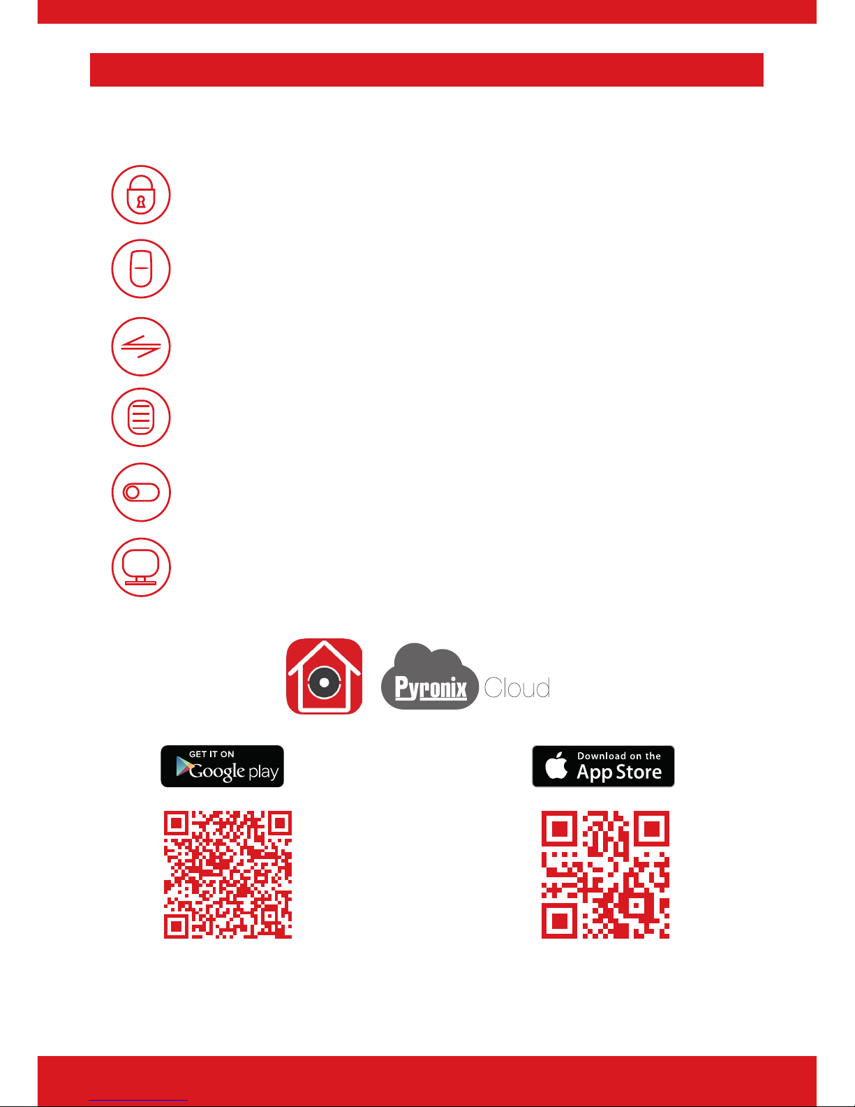
ProControl+
Connect to your home from anywhere
AES-256
Encryption
Set and unset your system
View your system status in real time, including: alarm, CO and
smoke detectors
Customise and receive push notifications from your system
Have instant access to your events and history log
Control appliances such as lights, garage doors, gates and
blinds
All using an encrypted, highly secure system, for extra peace
of mind that your family and home is safe and secure
https://apple.co/2N4DF51https://play.google.com/store/apps/
details?id=com.mcu.Pyronix&hl=en
Page 8
8
Enforcer V!0 User Guide
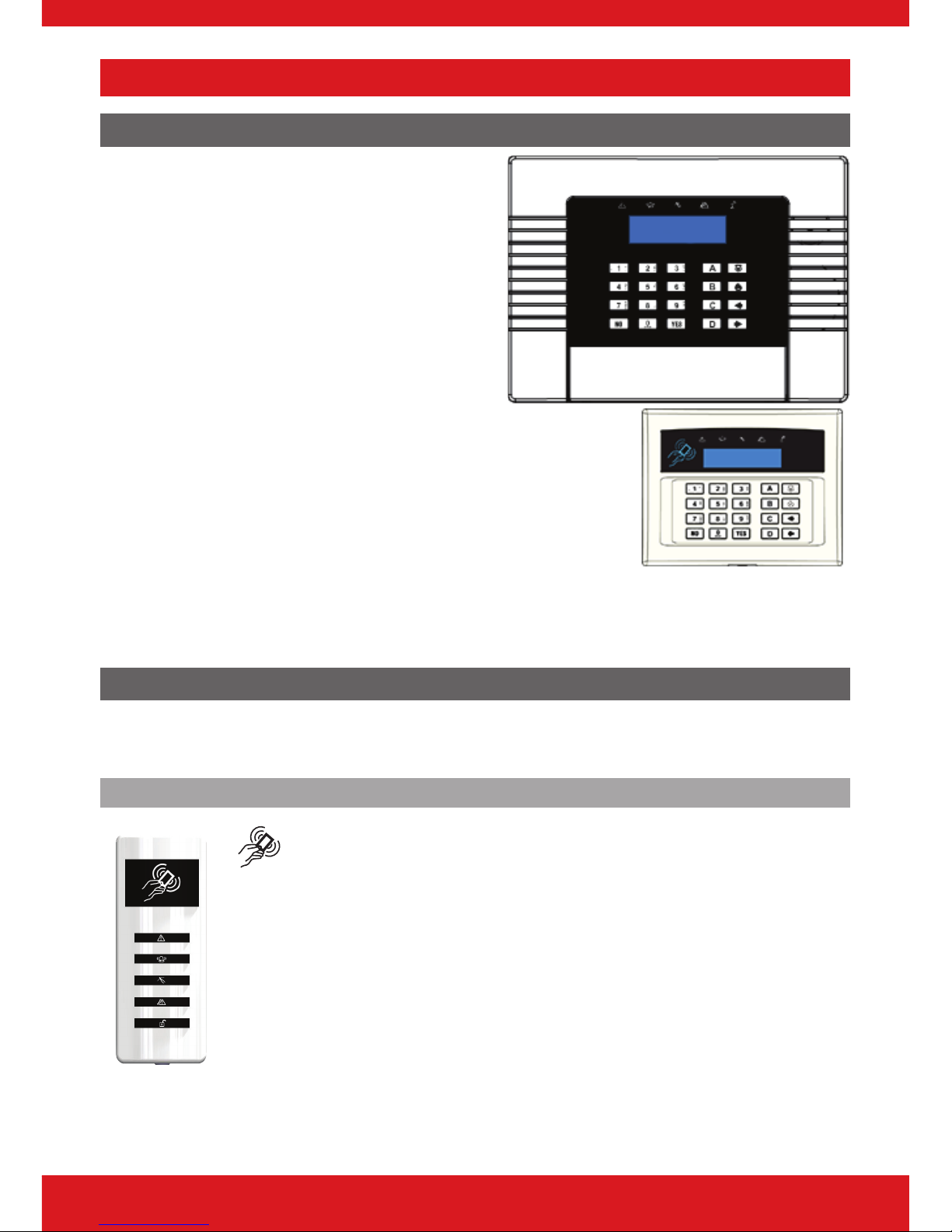
Setting Devices
The Wireless Panel Keypad and Additional Keypads
Additional wired keypads may also be connected
to the wireless control panel, please ask your
engineer for more information.
a = Exits the Master Manager menu and
selects Area A when setting.
b = Moves backwards in the Master Manager
menu and selects Area B when setting.
c = Enables chime, displays additional
information in the event log, and selects Area C
when setting.
d = Moves forward in the log, scrolls between options, enters
the Master Manager menu and selects Area D when setting.
f p = Not used.
[ ] = Directional buttons and enables/disables functions.
f = Enters menus and accepts programming preferences.
h = Cancels items, resets the panel and moves to next item in a menu item.
Proximity Tag Readers
Tag readers can be used for setting/unsetting, entry control or access control. Ask your
engineer for more details.
Internal
Proximity area (please present your tag here)
: Alert LED
; Alarm LED
< Tamper LED
= Fault LED
> Unset LED
Page 9
9
Enforcer V10 User Guide
External
To set/unset the system using the External Tag Reader, present a
pre-programmed tag to the centre of the reader.
The reader will display the system status:
Green LED means the system is unset.
Red LED means the system is set.
Present the tag again within 10 seconds and the system will set
or unset.
The system will then set depending on the type of exit mode programmed (nal door, timed
or push to set).
Wireless Keyfobs
The wireless keyfob has four buttons that may be programmed for specic purposes, these
options are programmed in the ‘EDIT USERS?’ section.
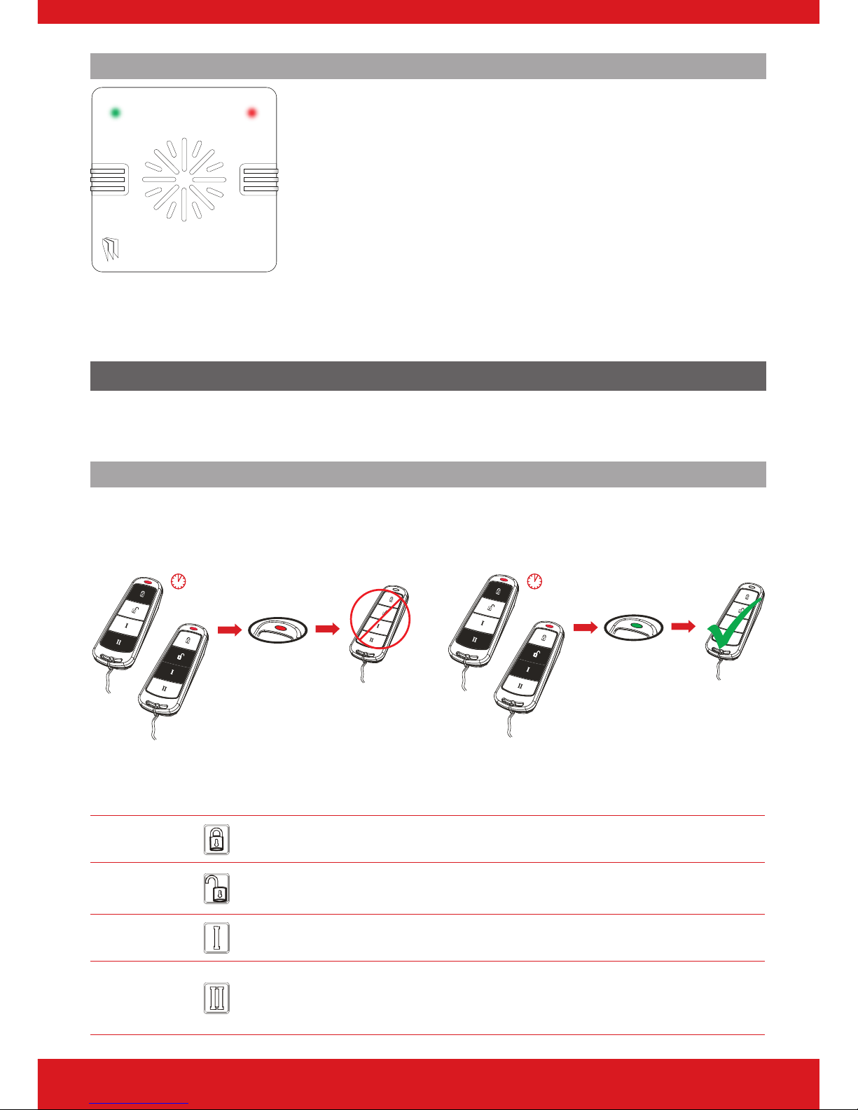
Locking the Keyfob
All four buttons on the keyfob may be locked so that any accidental presses will not aect
your wireless alarm system. For example, this protects the buttons from being pressed
accidentally if a keyfob is in someone’s pocket.
OR
OR
5 seconds 5 seconds
The buttons can be customised to operate as desired. The table below gives the defaults of
how each button is programmed.
LOCK When pressed, the Area A will start to set.
UNLOCK
When pressed, the wireless alarm system will unset any area that is
already set.
I BUTTON
When pressed, the Area B will start to set.
II BUTTON
When pressed, if the GREEN LED is shown then the wireless alarm
system will be unset. If the RED LED is shown then the wireless alarm
system will be set.
Page 10
10
Enforcer V!0 User Guide
Quick Setting
If one of the buttons is programmed as ‘Set Area’, the wireless alarm system can be set by
pressing the programmed button on the keyfob. The keypad will then start to count down
the exit time, wait for a ‘nal door’ to be opened and closed or wait for a Push to Set (PTS)
button to be pressed (depending what exit mode is programmed as by the engineer).
Once the alarm panel is in this ‘setting’ stage, it is possible to ‘quick set’ the system by pressing
the same button again; this will reduce the time to set to ‘immediate setting’. The alarm panel
will revert to the normal display with the time showing, but a beep will be heard conrming
the system has set.
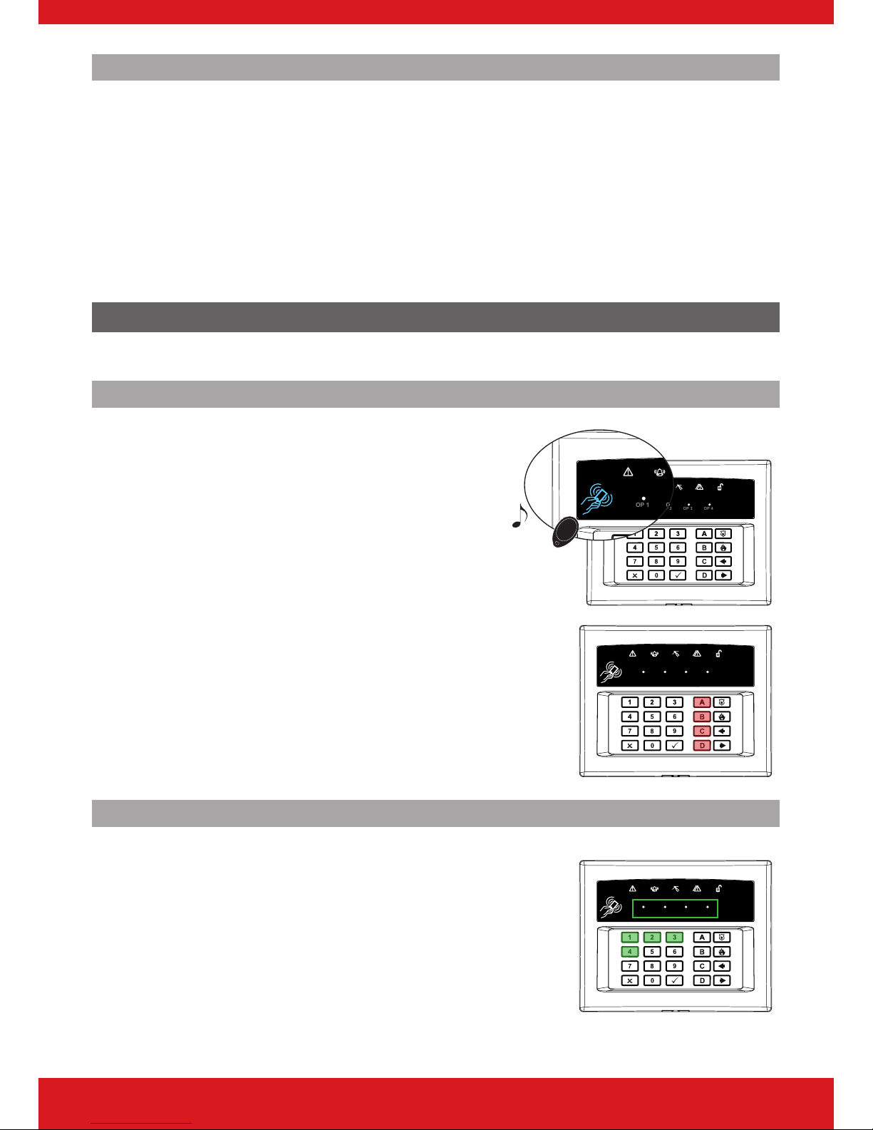
The Wireless Arming Station
Up to four wireless arming stations can be programmed on to the wireless alarm system.
Setting and Unsetting
If you are using a proximity tag to set or unset the
wireless alarm system, press any key rst (except
d), to ‘wake’ the wireless arming system before
presenting a tag.
Alternatively, if a user code is being used, then
enter the code. The wireless arming station will
automatically ‘wake’ once the rst button is pressed.
After a tag or code has been activated, choose the
area to set by pressing the a, b, c or d.
The key will illuminate indicating that area has been
chosen to be set. Once conrmed, press the t
key.
To unset, simply enter the user code.
OP
1 OP2
OP3OP 4
OP
1 OP2
OP3OP 4
“BEEP”
OP
1 OP2
OP3OP 4
Activating the Outputs
Press the d key and enter the Master Manager
code.
The keys 1 2 3 and 4 will illuminate.
The OP1–4 LEDs will illuminate once the 1-4
numeric keys have been pressed. Once illuminated,
it signies that the output has triggered. Press the
key again to deactivate the output.
OP
1 OP2
OP3OP 4
Using Predictive Text
Page 11
11
Enforcer V10 User Guide
Predictive Text
The wireless alarm system incorporates predictive text, so the system will predict which
word is being spelt.
For example, if you want to type ‘Daniel’, press 3 once and the name ‘David’ will appear.
Using the [ and ] keys move the cursor under the ‘v’ and press 6 twice to change it
to a ‘n’. The text will now change to ‘Daniel.’ Press f to accept.
If the word that you require does not appear in the list, just continue typing the word letter
by letter.
In addition, the a b c d keys are used as follows:
a = make the character into a capital
b = move cursor left
c = delete the character above the cursor
d = moves cursor right
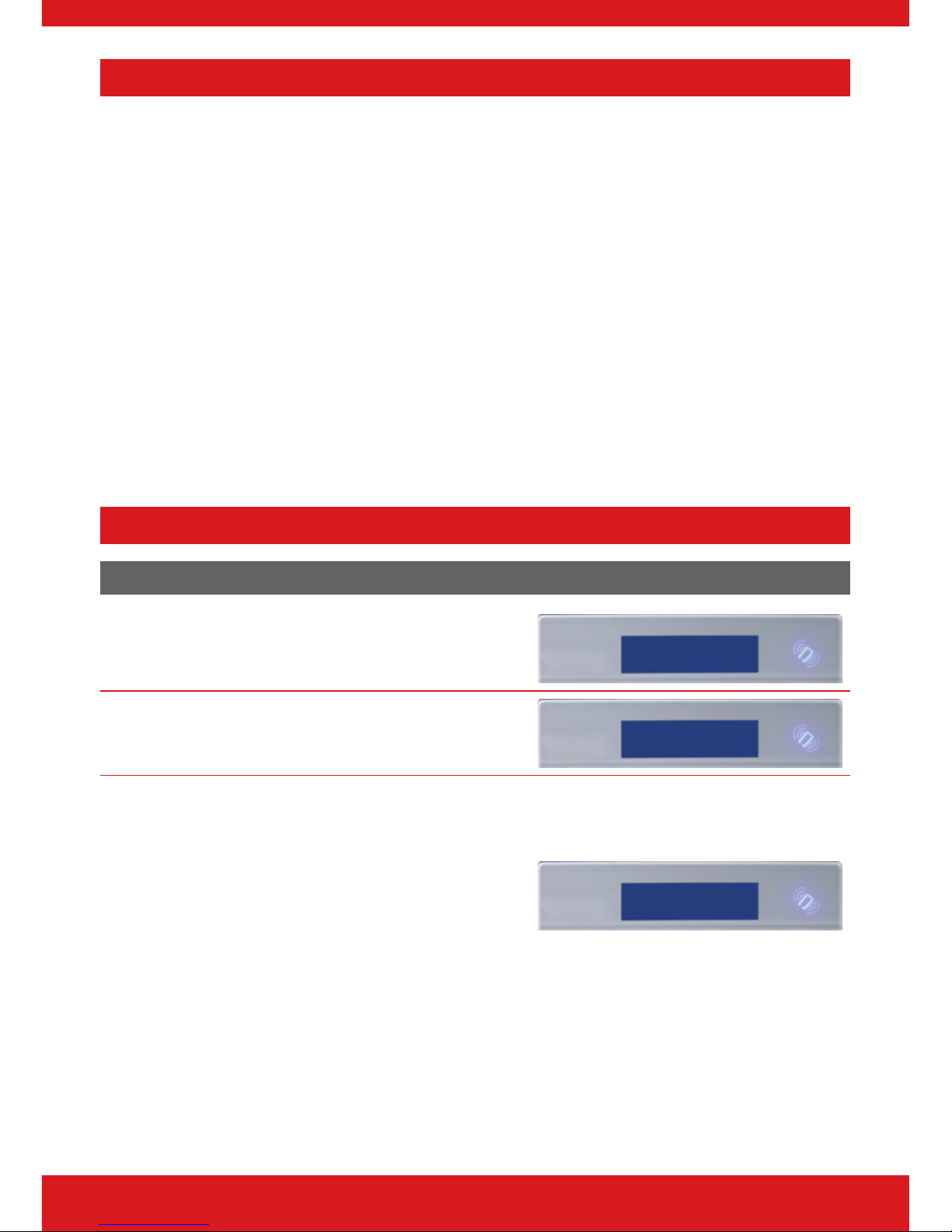
Setting the System
Using a PIN Code or Proximity Tag
Enter a valid PIN code or present a valid tag to the
symbol as shown.
Enter Your Code
[******]
Enter the area you wish to set and press f.
‘Please wait setting wireless’ will be displayed.
Set Areas?
[A ]
There are three dierent setting methods your
installer will instruct you through:
Final Door: Leave the building and make sure the
exit door is closed properly.
Timed: Make sure you leave the building before the
timer shown on the keypad expires.
Push to set: Press the push to set button installed by
your engineer to set the system.
Please leave via
Exit Route
Page 12
12
Enforcer V!0 User Guide
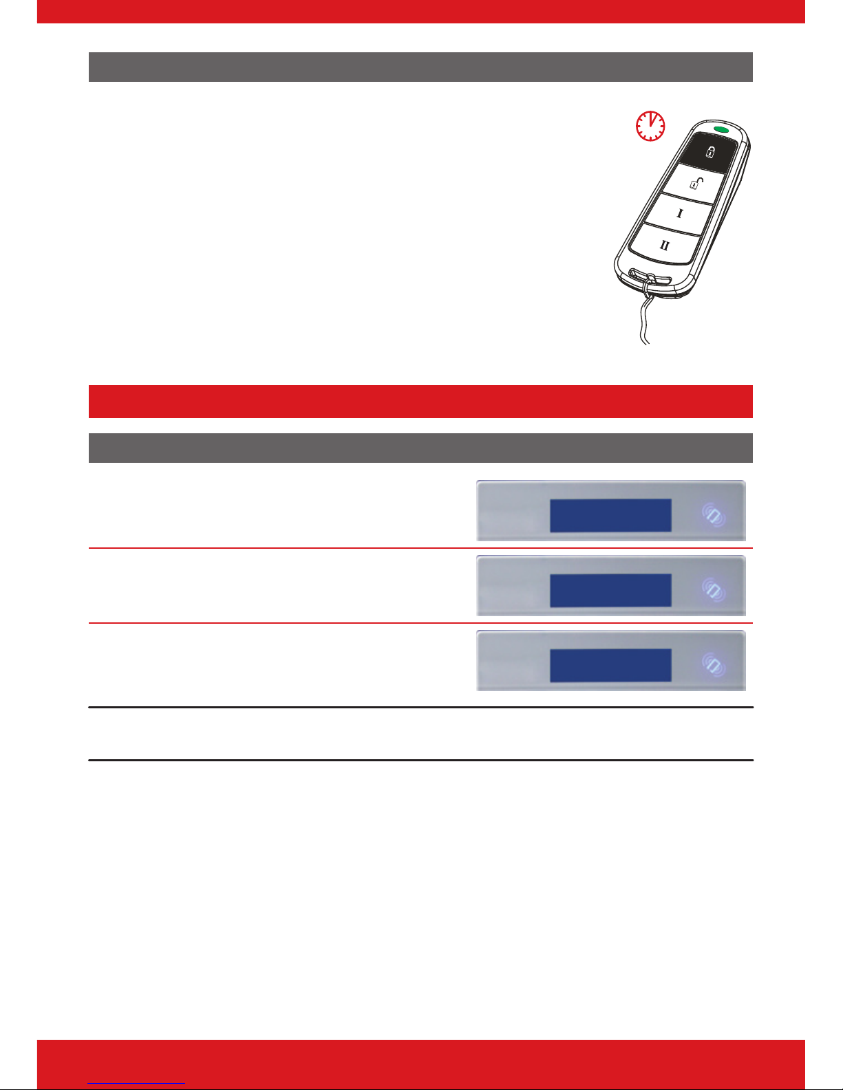
Using the Wireless Keyfob
To set via a keyfob. Pressand hold for more than 2
seconds.
The keyfob LED will start to ash green indicating that the
system is starting to set.
‘Please wait setting wireless’ will be displayed on the keypad
and the programmed area will begin to set.
To ‘quick set’, press and hold thekey again for four
seconds.
Once set, the keyfob LED will illuminate RED indicating that
the system is now set.
<2 seconds
Unsetting the System
Using a PIN Code or Proximity Tag
Enter the building, the ‘entry time’ will start.
ENTRY TIME [30]
Enter a valid PIN code or present a valid tag to the
symbol as shown.
Enter Your Code
[******]
The area that the code is assigned to will be unset.
Alarm Panel
Time 10:09 c
Please note: If ‘exi-set’ is disabled then the system will automatically unset that level set once a valid user
code or tag is presented.
Page 13
13
Enforcer V10 User Guide
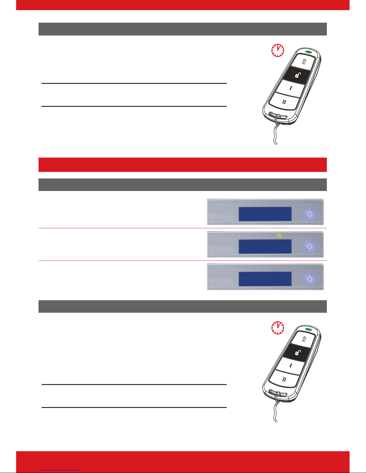
Using the Wireless Keyfob
To unset via a keyfob. Press .
The keyfob LED will ash green indicating that the system
has unset.
Please note: Unsetting with a keyfob will only be allowed if your
engineer has enabled this.
<2 seconds
Unsetting after an Alarm
Using a PIN Code or Proximity Tag
Enter a valid PIN code or present a valid tag to the
symbol as shown.
Enter Your Code
[******]
The alarm symbol will ash indicating there has
been an alarm activation and the keypad will
display which input has activated.
Alarm Silenced
Lounge
Press h to reset the system.
Alarm Panel
Time 10:09 c
Using the Wireless Keyfob
To unset via a keyfob. Press .
The keyfob LED will start to ash green indicating that the
system has unset.
Resetting the system after an alarm can only be done at
the keypad.
Please note: Unsetting with a keyfob will only be allowed if your
engineer has enabled this.
<2 seconds
Page 14
14
Enforcer V!0 User Guide
Using Proximity Tag Readers
Setting and Unsetting
If you have a tag reader installed, then it will be possible to set and unset the wireless alarm
system using a tag (the same tags can also be used on the readers on the main control panel
and keypads).
There are two types of readers that can be used with the wireless alarm system - the internal
tag reader and the external tag reader (used both indoors and outdoors).
Tags for the readers need to be programmed through the ‘Edit Users’ function in the Master
Manager Menu. The internal and external readers can be both assigned to individual areas,
this will need to be set up by your engineer.
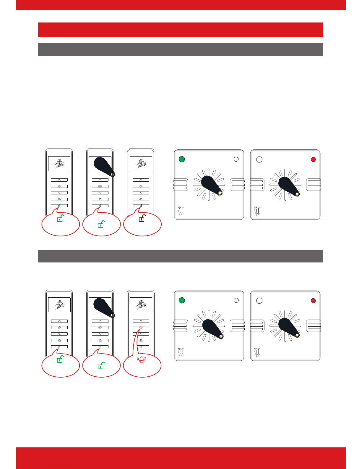
Unset
Set
Unset
Set
Entry Control
The readers may be used for entry control, which means they can operate automatic locks
for example as well as setting and unsetting the system. This can be set up by your engineer.
Unlocked
Locked
Unlocked
Locked
Page 15

15
Enforcer V10 User Guide
External Proximity Reader Instructions
Arming
Present a valid tag to the reader, the green LED will illuminate on the external reader, remove
the tag, the door will unlock, then present the same tag within 10 seconds and the system
will arm and the door will lock.
Disarming
Present a valid tag to the reader and then remove it, the status will be shown (the alarm
symbol will illuminate indicating the system is armed on the internal reader and the red LED
on the external reader), present the same tag within 10 seconds again and the system will
be disarmed, and the door will unlock.
Access Control/Entry Control
The readers can be used also for opening doors only without the ability to arm and disarm.
Please contact your installer for more information on this feature.
Anti-Code & Engineer Restore Facilities
Your engineer may have set up the system so that either an ‘Anti-Code’ or ‘Engineer Restore’
is required in order to fully reset the wireless alarm system
Please note: Your code will still silence the alarm, but it will not reset the system.
Anti-Code
After alarm activation has occurred, enter a valid
PIN code, present a valid tag, or press on the
keyfob to silence the alarm.
The keypad will display as shown to the right.
Take note of the number, on the screen and call
your Alarm Receiving Centre (ARC).
Press h.
Alarm Silenced
Restore G12298
When the time is displayed, enter the number given
to you by the ARC. ‘Engineer Restore Performed’ will
be displayed.
Press h.
Engineer Reset
Performed
Page 16

16
Enforcer V!0 User Guide
Engineer Reset
When the time is displayed, enter the Engineer
Code.
‘Engineer Reset Performed’ will be displayed.
Press a.
Restore
Required
Fault Indications & Unable to Set
Fault Indications
Control Panel
Any faults that occur on the system will be easily
recognised by the ashing ALERT LED.
Alarm Panel
Time 10:09 c
To see what the fault is, enter a valid PIN code, or
present a valid tag, or press on the keyfob.
Depending on how the system has been set up by
your engineer, it may be possible to set the system
with a fault, to do this press f.
Control Panel
Battery Fault
Please note: Any fault may aect the overall performance of your alarm control panel and therefore your
engineer should be contacted for further assistance if any fault is active.
Unable to Set
Control Panel Indication
If ‘unable to set’ is displayed, it indicates that an input
is open and the area where the input is should be
checked for open windows, pets, movement etc.
If the problem cannot be solved contact your
engineer, or omit the input.
Unable To Set
Input 01
Keyfob Indication
If the panel is unable to set for any reason, the keyfob status LED ashes amber indicating a
fault is on the system.
Page 17

17
Enforcer V10 User Guide
Advanced Functions
Chime
The chime can be used for any input on the system.
This can be set up by your engineer.
To enable the chime on the keypad, when the time
is displayed, press c.
‘c’ will be displayed on the right side of the keypad
display. Press c again to clear the chime feature.
Alarm Panel
Time 10:09 c
Omitting Inputs
On occasion, a detector may need to be isolated if
a room is occupied.
Enter your User Code.
Press f.
Select the inputs that need to be omitted’
Press a.
After 10 seconds the exit time continues.
Omit Day Al [01]
Please note: Inputs have to be programmed as omittable by your engineer for this feature to operate.
Keypad Hold Up
A ‘hold up’ alarm will be generated when 1 and
7 are pressed and held down for 2 seconds (this
time period can be altered by your engineer).
Alarm Silenced
2 Key HU
Please note: The keyfob can also be programmed to provoke a hold up alarm. All hold up alarms including
duress codes must be enabled by the engineer.
Page 18

18
Enforcer V!0 User Guide
Master Manager Mode Overview
The Master Manager Menu has the following functions:
Please note: The options visible will depend on which modem is installed in the panel.
Set Date and Time
Programs the date and time.
Operate User Outputs
Activates/deactivates user automation outputs that are used to remotely activate devices,
such as electronic gates & lights.
Omit Inputs
Omits inputs programmed as ‘Day Alarm’ only.
Edit Users
Adds/Edits/Deletes User PIN codes, tags and keyfobs.
Review Logs
Displays all event log information.
SMS Phonebook
If SMS texting is enabled, there can be up to 10 mobile numbers programmed to send SMS
alarms. Please discuss this feature with your installer if required.
Please note: Third party SIM cards only.
Voice Phonebook
Edits the telephone numbers that the panel is programmed to send voice messages to.
Set Up App Data
If the ProControl+ App has been enabled, this function will control the settings.
Wi-Fi Setup
Adds or changes a Wi-Fi connection with your router.
Walk Test
Tests each input.
Page 19

19
Enforcer V10 User Guide
Siren Test
Tests all external sounders (wired or wireless).
Dial Out Menu
Calls the UDL software.
Allow Engineer Menu
Enables or disables engineer access.
Block UDL Set
Blocks remote setting from the PC software.
Block UDL
Blocks uploading/downloading from the PC software.
System Sounds Demo
Demonstrates all the sounds of the alarm system.
Exit Manager Mode
Exits Master Manager mode.
Please note: The Master Manager code allows access to all the options above. A User Code has access to the
‘User Menu’ which includes the functions: ‘Operate User Outputs’, ‘Change Code’, ‘Review Logs’, ‘Walk Test’,
‘Siren Test’. ‘Allow Engineer Menu’, and ‘Exit User Menu’.
Entering Master Manager Mode
Press d.
Enter the Master Manager code or present the
Master Manager tag.
Press b or a to scroll through the dierent
functions.
Enter Your Code
[ ]
Page 20

20
Enforcer V!0 User Guide
Exiting Master Manager Mode
Press b or h keys to scroll through until ‘EXIT
MANAGER MODE?’ is displayed.
Press f.
Or, when a main menu item is displayed (capital
letters) press a.
EXIT MANAGER
MODE?
Master Manager Mode Options
Set Time and Date
Press b or h to scroll to ‘SET DATE & TIME?’.
Press f.
SET DATE & TIME?
Enter the year.
Press f.
Year (00-99)
[18]
Enter the month.
Press f.
Month (01-12)
[09]
Enter the day.
Press f.
Day (01-30)
[04]
Enter the hours.
Press f.
Hours (00-23)
[18]
Enter the minutes.
Press f.
Minutes (00-59)
[00]
Select whether DST is to be activated.
Press f.
DST Adjust?
Yes [1]
Page 21

21
Enforcer V10 User Guide
Operate User Outputs
Press b or h to scroll to ‘OPERATE USER
OUTPUTS?’.
Press f.
OPERATE USER
OUTPUTS?
Select the output to be operated by using the [
or ] keys and press f.
Select Output
[01]
Press f trigger output on and o.
Press h to exit.
Output Off
Omit Inputs
Press b or a to scroll to ‘OMIT INPUTS’.
Press f
Alarm Silenced
Restore G12298
Enter the inputs you require to be omitted for the
next setting procedure.
Press f
Engineer Reset
Performed
Please note: This only omits inputs programmed as day alarm and are only omitted until the system has
been set and unset.
Edit Users
The ‘EDIT USERS’ function allows adding, editing and deleting of both master manager and
user codes, tags and keyfobs.
The control panel can have up to 80 users programmed. Each of the users are allocated a
code, tag or a wireless keyfob.
Please note: A maximum of 32 users can have a wireless keyfob allocated.
Page 22

22
Enforcer V!0 User Guide
Button Actions
Each wireless keyfob has four buttons that can be programmed for any of the following
functions.
No Action
Disables the button.
Show Status
Prompts the LED on the keyfob to indicate whether the system is set or unset.
Set Area
Sets the chosen area(s)
Unset Area
Unsets the chosen area(s)
Operate Output
Triggers an output on the panel (programmed by Engineer)
Flexi-set
Flexi-set allows you to choose which level/area to set if a user code or tag is assigned to one
or more levels/areas. If this function is disabled, when a user code is entered or proximity
tag presented, the system will automatically set the levels/areas that the user is assigned to.
Please note: Any proximity tags that are to be used on a standalone tag reader must have exi-set set to
‘No’.
Adding a New User
Press b or h to scroll to ‘EDIT USERS?’.
Press f.
EDIT USER?
To add a new code, tag, or keyfob press f. Press
A to delete or change a user code (see further down
for details).
Add New User?
Press [ or ] to choose a user number. Press
f.
Empty [01]
Enter the new code, present a tag or press and hold
a keyfob button until the display changes. Once
‘asterisks’ appear, the tag or user code will be now
assigned to this user. Press f.
Enter User Code
[******]
Page 23

23
Enforcer V10 User Guide
Please note: The next three options will only appear if you are adding a wireless keyfob.
If a keyfob is programmed, the 'User Name' will be
displayed on the keypad.
Enter the user name. Press f.
User Name
_
Press [ or ] to choose the button to program.
Press f.
Select Button
Lock [1]
Press [ or ] to choose the action assigned to
the button. Press f.
Button Action[2]
Set Area
Please note: The following screens will not be displayed if you have programmed a wireless keyfob.
Press [ or ] to choose between 'User' or
'Manager'. Press f.
User Type
User [0]
Select the areas that the user will be assigned to: A,
B, C or D. Press f.
User Areas
[ABCD]
Press [ or ] to choose between 'Unset/Set',
'Unset Only', 'Set Only' or 'None'. Press f.
User Set Options
Unset / Set [0]
Press [ or ] to enable or disable 'Flexi-Set'.
Press f.
Flexi Set
No [0]
Enter the user name.
Press f.
User Name
_
Press f to delete or change a user.
Delete/Change
User?
Page 24

24
Enforcer V!0 User Guide
Deleting a User
Press [ or ] to scroll through the users, or
enter the user number and press f.
Code [01]
Press f to delete a user, or press h to change
a user.
Delete User?
Change User
Press f to change a user code, and follow the
screen shots previously.
Change User?
Change Master Manager Code
To edit the Master Manager Code, press f.
Enter the new code or present a tag. Press f.
Repeat the procedure mentioned previously.
Change Master
Manager Code?
Review Logs
The ‘Review Logs’ function monitors all operational information of the wireless alarm system,
such as setting/unsetting information and alarm activations etc.
Press b or h to scroll to ‘REVIEW LOGS?’.
Press f.
REVIEW LOGS?
Press f.
Panel Log?
The most recent event will be displayed, press b
or d to scroll backwards and forwards through
the log.
09/09 10:09:00
User Added
Press the c key to show more information (such
as which input activated, or which user set the
system etc.)
Daniel
Page 25

25
Enforcer V10 User Guide
Set Up App Data
This menu is required in order to use the smart device application to control the system.
When setting this menu up it is important to take note of the ‘System ID’, ‘App Password’ and
‘Cloud Password’.
Please note: This menu will only be visible with a ProControl+ compatible module is installed.
Press b or h to scroll to ‘SET UP APP DATA?’.
Press f.
SET UP APP
DATA?
Press [ or ] to enable or disable using
ProControl+. Press f.
Use App?
Yes [1]
Take note of the System ID. This will be needed for
the ProControl+ App setup. Press f.
System ID
AABBC7DD
Your engineer should have already set up the
PyronixCloud and a password. Press f.
Cloud Password
_
At this point you choose ‘normal’ security level or ’high’ security level. This does not compromise the
security between the control panel and ProControl+ but if high is selected, the panel will automatically
generate a 32 digit app password for you.
Low Security
Press d to select ‘Normal’ . Press f.
Security Level
Normal [0]
Create an App Password. This is entered on
ProControl+ when connecting to the system. Press
f.
App Password
_
Press [ or ] to enable or disable the polling to
the cloud at all times. Press f.
Alwys Poll Cloud
No [0]
Page 26

26
Enforcer V!0 User Guide
High Security
Press d to select ‘High’ . Press f.
Security Level
High [1]
Press f to generate a high security password.
Generate App
Password Key?
Take note of the key. Part 1 is shown rst, press f
for part 2.
Key Part 1 ABCD
EDFG IJKL MNOP
Press f to view the password again or press
h to move on to the next menu option.
View App
Password Key?
If you would like to send the password to your
phone as an SMS message, press f and enter
your mobile number. If not, press h.
Send Password
Key in a text
Press [ or ] to enable or disable the polling to
the cloud at all times. Press f.
Alwys Poll Cloud
No [0]
Please note: The password key sent to your mobile phone must be kept safe. UK numbers can be entered
with or without an international dialling code (e.g. +44). If you need to enter an international dialing code
to send the key to a foreign SIM card, use the a key to enter the ‘+’ symbol. This feature works with 3rd party
SIM cards only.
Wi-Fi Setup
If a Wi-Fi module is installed in your system, the SSID and password will need to be set up in
this menu.
1. Go into the Master Manager menu. Press h
until the option ‘WI-FI SETUP?’ is displayed.
Press f.
WI-FI SETUP?
2. ‘Setup with WI-FI Device?’ will now be on the
LCD screen. Press h to program the wireless
network manually.
Setup with WI-FI
Device
3. ‘SSID?’ will now be displayed, press f and
enter the SSID (name of the wireless network).
Press f to return to ‘SSID?’.
SSID?
Page 27

27
Enforcer V10 User Guide
4. Press h and the LCD will change to
‘Password?’ Press f and enter the password
for the wireless network. Press f to return
to ‘Password?’.
Password?
5. Press h and the panel will display the Wi-Fi
signal strength.
Please note: This needs to be 11 or above
Signal Strength
16
6. Press f and the panel will return to ‘WI-FI
SETUP?’. Press a to exit and save.
WI-FI SETUP?
SMS/Voice Phonebook
If SMS or voice messages are activated, there can be up to 10 mobile numbers programmed
which can be changed in this function. If ‘do not use’ is shown on the display of a number,
then a telephone number already exists that is communicating to an Alarm Receiving Centre
(this can only be changed by your engineer).
Press b or h to scroll to ‘PHONEBOOK?’.
Press f.
PHONEBOOK?
Press b or d to scroll through the dierent
telephone numbers.
Press f to edit the number.
SMS Numbers?
Enter the mobile number. Press f.
Press [ or ] to enable or disable the number.
Press f.
Mobile No. _
Walk Test
The ‘Walk Test’ function allows the testing of all programmed inputs on the wireless alarm
system.
Press b or h to scroll to ‘WALK TEST?’.
Press f.
WALK TEST?
Page 28

28
Enforcer V!0 User Guide
Select which area set to walk test by using the
keypad to select a letter. Press f to walk test the
inputs allocated in that area or press the h to
walk test an input individually.
Please note: In order for the walk test to function correctly,
one area must be selected only.
Walk Test Areas
[ABCD]
Walk Test Area
The display will cycle through each of the inputs to
be walk tested. Trigger each input individually and
it will be removed from the cycle. When all inputs
are triggered the keypad will display ‘Walk Test
Complete’.
Walk Test
Input 01
Walk Test Individual Inputs
Press [ or ] to scroll through the dierent
inputs and press f to walk test that input.
Walk Test Input
[01]
Siren Test
This function is used to test any wired or wireless output on the panel programmed as ‘[0014]
Siren Any’ and ‘[0016] Strobe Any’.
Press b or h to scroll to ‘SIREN TEST?’.
Press f.
SIREN TEST?
This tests both the siren and strobe outputs. Press
f.
Testing Siren...
Dial Out Menu
This function is used to force the panel to dial out to UDL software.
Please note: Do not use this function unless you have been instructed to by your engineer.
Allow Engineer Menu
If this function is enabled, the engineer will require authorisation from you before they can
access the engineering menu.
Press the b or h keys to scroll to ‘ALLOW
ENGINEER MENU?’. Press f.
ALLOW ENGR MENU?
Page 29

29
Enforcer V10 User Guide
Press [ or ] to select either ‘Yes’ or ‘No’. Press
f.
Allow Engr Menu?
Yes [1]
Block UDL Set
Your wireless alarm system may be congured so that your alarm installation company can
remotely set/unset. Should you wish to block this access, you can enable this function.
Use the b and h keys to scroll to ‘BLOCK UDL’.
Press the f.
BLOCK UDL?
Press [ or ] to select either ‘Yes’ or ‘No’. Press
f.
Block UDL?
No [0]
System Sounds Demo
This function showcases all of the sounds that may occur from the panel during operation.
Use the b and h keys to scroll to ‘SYSTEM
SOUNDS DEMO?’. Press the f.
SYSTEM SOUNDS
DEMO?
Press [ or ] to scroll through the dierent
system sounds. Press f.
Sound to Play
No Sound [00]
Page 30

30
Enforcer V!0 User Guide
ProControl+ Smart Device Application
Getting Started
Downloading the App
The app can be downloaded from either the
Apple App Store or on Android from the Google
Store by searching Pyronix.
Smart Device Minimum Requirements
iOS 7.0 or later
Android 4.0 or later
Registering to the ProControl+ Service
1. Download ProControl+
2. On the ‘Login’ screen, select ‘Register’.
3. Read the ‘Terms of Service’ and ‘Privacy Policy’ then tap the check
box to agree.
Choose to either register via mobile phone number or email address.
4. Select your Country/Region from the list provided then tap the
‘tick’ in the top right corner.
5. Enter the email address you wish to register with and select ‘Next’.
(If you are registering with your mobile phone number, enter that here.)
Page 31

31
Enforcer V10 User Guide
6. Enter the 4 digit security code you will receive via email or text
message, depending on your earlier registration selections.
7. Once you have entered the code, select ‘Next’.
8. Create a ‘User Name’ and password for your account.
9. Conrm the password and select ‘Finish’. ProControl+ will
automatically log in using these credentials.
Adding a Control Panel to ProControl+
1. Tap the ‘+’ in the top right corner of the homescreen.
2. Select ‘Intrusion panel’ from the drop down menu.
3. Enter an alias for the system (this is how the system will appear on
your app) and enter the ‘System ID’.
(This can be found in the Master Manager menu in ‘SET UP APP DATA?’)
4. Tap ‘Add’ in the top right corner.
Page 32

32
Enforcer V!0 User Guide
Basic Controls
Connecting to the Panel
1. Select the intruder system from the homescreen of ProControl+
that you wish to set.
2. Enter your ‘User Code and ‘App Password’ and tap ‘Login’.
Please note: Whilst you are connected to the panel via ProControl+, you will not receive notications. To
disconnect, press
in the top right corner of the system controls screen.
Page 33

33
Enforcer V10 User Guide
Intruder Alarm Homescreen
Outputs
Tap the output to
trigger it. Whilst
triggered, the icon will
turn red. Tap to turn
o.
Disconnect from system
Tap this to disconnect
from the system and
return to the homescreen
Inputs in area
Tap this to view all the
inputs allocated in
the above area.
Input status
Displays the status of
the input such as
open, closed, tamper
or bypassed.
Control panel settings
Tap here to view the
system ID, change the
alias, view history/logs
and delete control panel.
Set/unset padlock
Displays whether the
area is set or unset. To
arm the area, tap the
padlock and once set
the icon will change to
a red closed padlock.
Tap again to unset the
area.
Omit input slider
If the input has been
programmed so it can
be omitted, this is
used to operate that
function. Tap to slide
on and o. Whilst the
bar is green, the input
is active
Input information
Tap the cog to view
information about the
input such as which
areas it has been
allocated in, the device
location and its status.
Please note: If there has been alarm event, the red padlock will appear as a red bell instead. To unset,
tap the red bell and it will return to a green padlock.
Page 34

34
Enforcer V!0 User Guide
Advanced Controls
History
1. Tap the control panel settings icon in the top right corner.
2. A menu for the control panel will be shown. From this page
select ‘History ’.
3. Scroll up and down to see the history of events.
4. To go back to the control panel settings page, click
in the top
left corner.
Page 35

35
Enforcer V10 User Guide
Setting/Unsetting Logs
1. Tap the control panel settings icon in the top right corner.
2. A menu for the control panel will be shown. From this page
select ‘Arming/Disarming Logs’.
3. This screen shows you the last time each area was set and unset.
4. To go back to the control panel settings page, click
in the top
left corner.
Acknowledging a Voice Call
When you receive a phone call from your control panel, pick up the phone (or press the
answer button /option on your mobile phone) and the control panel will listen until it hears
an audible response on the line: simply answer ‘hello’ or make any other audible sound.
Once the panel detects the sound you have made – it will begin playing a sound recording
that corresponds to the events that have been triggered. A typical message will tend to
include details of which user set or unset your system, what event occurred or which sensor
triggered. The system contains countless voice recordings that are assembled into the
correct message for the specic situation at hand.
Page 36

36
Enforcer V!0 User Guide
If your alarm system has been congured by your engineer to request an acknowledgement
code – then once the details of the alert message have been played it will be requested at
the end of the phone call from the panel. This is a numerical code that you must enter on
your phone followed by the # (hash) key.
Please note: The factory default for this acknowledgement code is; 5 (followed by the # key)
Certication
All wireless devices comply with the following EU requirements
EMC 2014/30/EU
Low Voltage 2014/35/EU
RE Directive 2014/53/EU
RoHS 2011/65/EU
And meet the following standards where relevant:
EN 61000-6-3:2007 +A1:2011
EMC. Generic emission standard. Residential, commercial
and light industry
EN 50130-4:2011 +A1:2014
Immunity requirements for components of re, intruder
and social Wireless Alarm Systems
EN 60950-1:2006 +A12:2012
Information technology equipment. Safety. General
requirements
EN 50131-5-3:2005+ A1:2008
Grade 2. Interconnections for equipment using radio
frequency techniques
ETSI EN 301489-3:2000
EMC. Radio equipment. Part 3: Short range devices (SRD)
9kHz to 40GHz
ETSI EN 300 220 EMC. Receiver Class 1, Environmental Category 1
CERT/ERC Recommendation 70-03 Annex 1
Compliant operation is only guaranteed when installed and operated according to the
relevant installation and user manuals.
Page 37

37
Enforcer V10 User Guide
Installation Information
Engineer Information
Alarm Company
Date of Installation
Site Reference
Engineer Name
Engineer Contact Number
Installed to Grade
Environmental Class II
Your panel is suitable for use in installations designed to meet the European requirements
of Security Grade 2, Environmental Class II. When all parts are working normally, this
equipment in combination with the PSTN or GSM and suitable ARC equipment will meet
the requirements of ATS2 /LAN or WiFI or GPRS meet the requirements of ATS5
External set/unset readers and wireless sirens meet the requirements of environmental class
4.
Number of Code Diers: Tag hex code.
Your panel is designed to automatically inhibit certain functionality. The factory default
settings are shown below:
Keypad
After 30 key presses without entering a valid code, keys are disabled for 90 seconds. After
reinstatement, this will be repeated after each 7 key presses until a valid code is entered.
Proximity Tag Reader (Or Reader at a Keypad)
After 6 presentations of an invalid tag, the reader will be disabled for 90 seconds. After
reinstatement, this will be repeated for each invalid tag until a valid tag is used.
Page 38

38
Enforcer V!0 User Guide
Input Table
Input No. Input Name Input Areas Description
1
2
3
4
5
6
7
8
9
10
11
12
13
14
15
16
17
18
19
20
21
22
23
24
25
26
27
28
29
30
31
32
Page 39

39
Enforcer V10 User Guide
Input No. Input Name Input Areas Description
33
34
35
36
37
38
39
40
41
42
43
44
45
46
47
48
49
50
51
52
53
54
55
56
57
58
59
60
61
62
63
64
65
Page 40

40
Enforcer V!0 User Guide
Input No. Input Name Input Areas Description
66
Users
Standard Users
User No. User Name Code/Tag/Keyfob Area Access
1
2
3
4
5
6
7
8
9
10
11
12
13
14
15
16
17
18
19
20
21
22
23
24
25
26
27
28
Page 41

41
Enforcer V10 User Guide
User No. User Name Code/Tag/Keyfob Area Access
29
30
31
32
33
34
35
36
37
38
39
40
41
42
43
44
45
46
47
48
49
50
51
52
53
54
55
56
57
58
59
60
61
Page 42

42
Enforcer V!0 User Guide
User No. User Name Code/Tag/Keyfob Area Access
62
63
64
65
66
67
68
69
70
71
72
73
74
75
76
77
78
79
80
Please note: Users 15 to 20 are considered special users and can send specication events from the
PyronixCloud. Please ask you engineer for more details.
Page 43

Guard, Duress and Dial Back Users
User No. User Name User Areas Guard, Duress or Dial Back
1
2
3
4
5
6
7
8
9
10
Page 44

 Loading...