


Programming Manual
RINS1904-1
EN50131-1:2006+A1:2009
EN50131-3:2009
EN50131-6:2008
EN50131-5-3:2005+A1:2008
PD6662:2010+IA:2015
Software Version >10
PIEZO WARNING
The Enforcer system contains a
100dBA siren, please be aware
of this after an activation
Enforcer
Time 10:09 c

Enforcer: Programming Manual
CONTENTS PAGE
1. The Engineer Menu .................................................................................................................................. 3
1.1 Accessing The Engineer Menu ............................................................................................................... 3
1.2 Exiting The Engineer Menu ................................................................................................................... 3
1.3 Useful Engineer Menu's ....................................................................................................................... 3
2. General Information ................................................................................................................................ 4
2.1 Default Codes .................................................................................................................................... 4
2.2 Initial Power Up .................................................................................................................................. 4
2.3 Testing The Keypad ............................................................................................................................ 4
2.4 Wired Keypads/Readers ....................................................................................................................... 4
2.5 Text Programming .............................................................................................................................. 5
2.6 Engineer Function: Set System ............................................................................................................. 6
2.7 Engineer Function: Forced Arm On Inputs .............................................................................................. 6
3. The Engineer Menu .................................................................................................................................. 7
3.1 Set Date & Time ................................................................................................................................. 7
3.2 Wireless Device Control ....................................................................................................................... 7
3.3 Change Inputs ................................................................................................................................... 9
3.4 Choose Mode .................................................................................................................................... 11
3.5 Install ZEMs ...................................................................................................................................... 12
3.6 Change Outputs ................................................................................................................................ 12
3.7 Assign Keypads/Readers ..................................................................................................................... 13
3.8 Change Timers .................................................................................................................................. 16
3.9 Codes And Users ............................................................................................................................... 16
3.10 Volume Control ................................................................................................................................ 17
3.11 System Options ............................................................................................................................... 18
3.12 Review Logs .................................................................................................................................... 21
3.13 Engineer Tests................................................................................................................................. 21
3.14 Diagnostics ..................................................................................................................................... 24
3.15 Engineer Reset Options ..................................................................................................................... 27
3.16 Alarm Response ............................................................................................................................... 28
3.17 Set Up Downloading ......................................................................................................................... 28
3.18 Software Revision ............................................................................................................................ 30
3.19 Clean Start ..................................................................................................................................... 30
Appendix A. Defaults ............................................................................................................................ 31
Appendix B. Input Types ....................................................................................................................... 35
Appendix C. Timers .............................................................................................................................. 36
Appendix D. Output Types ..................................................................................................................... 37
Appendix E. Fault Codes ........................................................................................................................ 40
Default Codes: User Code: ‘Blank’ Master Manager Code: 2222. Engineer: 1111
Factory Default Codes:
Clean start with the code ‘2000’ (UNGRADED)
Clean start with the code ‘2020’ (Grade 2)
Other Codes:
Keypad Security Code: ‘2000’
Delete All Wireless Data: ‘2000’

Enforcer: Programming Manual
1. The Engineer Menu
The Engineer Menu must be accessed in order to program all system configurations.
NOTE 1: All tamper alarms (including case tamper), will be disabled once in the Engineer menu.
NOTE 2: All personal attack and fire alarms will not cause an alarm in the Engineer Menu.
1.1 Accessing The Engineer Menu
Access to the Engineer menu will be allowed if the Enforcer is unset. If set, the Enforcer must be
unset first via a valid user code/tag/keyfob in order to gain access. If the 'Allow Engineer Menu'
function in the Master Manager Menu is set as 'No', the message ‘Authorisation Required’ will be
shown and access will be denied until this option is set as 'Yes'.
1. Enter the engineer code (default 1111).
2. If any faults that are active, they will be displayed
now on the screen. Press A and enter the
engineer code again.
3. 'SET DATE & TIME’ is displayed.
4. Engineers Menu has been accessed.
5. Refer to page: 7 for all functions.
When the Engineer Menu is accessed, a high pitch tone is generated intermittently.
NOTE 1: It is essential that a factory default (CLEAN START) is performed after initial power up to
ensure that the correct defaults have been chosen (see page: 30).
NOTE 2: Refer to Appendix E, page: 40 for all fault code display descriptions.
SET DATE & TIME?
1.2 Exiting The Engineer Menu
When a Main Menu Item (a menu that is in capital letters)
is displayed, press or scroll to 'EXIT ENGINEERS
MENU' and press .
EXIT ENGINEER
MENU?
1.3 Useful Engineer Menu's
WIRELESS DEVICE CONTROL (Page:7): Learns and deletes all wireless inputs, bells and arming
stations. To learn wireless keyfobs enter the Master Manager menu and scroll to CHANGE CODES.
(Refer to the user manual).
CHANGE INPUTS (Page: 9): Programs all input types, attributes, areas and names and on the
Enforcer.
ASSIGN KEYPADS/READERS (Page: 13): Assigns wired/wireless keypads and readers, and
enables readers for entry control. NOTE: Keypads and Readers must be addressed at the device and
at the keypad.
CODES AND USERS (Page 16): Changes the ‘Engineer code’, ‘Master Manager code’ and ‘Duress
codes’. To change user codes enter the Master Manager menu and scroll to ‘EDIT USERS’. (Refer to
the user manual).
CHANGE OUTPUTS (Page: 12): Programs any outputs and assigns output modules to the Enforcer.
DIAGNOSTICS (Page: 24): Displays power, input status, wireless arming stations, wireless signal
strength and wireless battery levels.
COMMUNICATIONS Enables a modem (if connected) and allows signalling via communication
formats or SMS, and enables the HomeControl+ App and Cloud. Please refer to the ‘Communications
Guide’
Page: 3

Enforcer: Programming Manual
2. General Information
2.1 Default Codes
User: ‘Blank’ Master Manager: 2222 Engineers: 1111
2.2 Initial Power Up
Power up the Enforcer system, an alarm will be generated. Proceed to the Enforcer keypad, which will
display (from power up):
1. Once power has been applied to the Enforcer,
'Please Wait' will be displayed, followed by '485
Comms Lost'. After approximately one minute, the
Enforcer will the time on the display, indicating the
system is ready to use.
2. The Enforcer is defaulted to keypad address '0'.
Please Wait...
2.3 Testing The Keypad
With the system unset, press the key for 5 seconds at any keypad. This will cause all the LEDs on
that keypad to illuminate, and the LCD screen to display each pixel. The keypad will revert to normal
display after the test which will last about 10 seconds.
2.4 Wired Keypads/Readers
The Enforcer Keypad and Additional Keypads (EUR0-LCDPZ)
3 additional wired keypads may also be connected to the Enforcer. Refer to the ‘Installation
Manual’ for all connections.
KEY FUNCTIONS:
a = Exit Engineer and Manager menu / Selects Area A.
b = Moves backwards to the previous menu item / Selects Area B.
c = Enables chime and displays additional information in the log / Scrolls back ‘one’ in a sub
menu / Selects Area C.
D = Moves forward in the log / scrolls between options and enters the master manager menu
/Selects Area D.
f p = Not used. [] = Directional buttons.
I = Selects items and enters menus.
A = Cancels items, resets the panel and moves to next item in a menu item.
NOTE 1: If any additional keypads are installed on the Enforcer, it is possible to access the
Engineer Menu on any keypad. For example, if the Engineer menu is accessed on keypad address
0, the other keypads will display ‘System Busy’. To access the Engineer menu on any other
keypad, press the key on the relevant keypad and the Engineer menu will be displayed.
NOTE 2: A Wireless Keypad can be connected to set/unset (LEDRKP-WE)
Page: 4

Enforcer: Programming Manual
The Internal Tag Reader (EUR-107)
The Internal tag reader can be used for setting/unsetting, entry control or access control. Refer
to the installation manual for all connections.
Tag Area (Where a valid tag must
be presented to set/unset)
Alert LED
Alarm LED
Tamper LED
The External Tag Reader (EUR-108)
The Internal Tag Reader can be used for setting/unsetting, entry control or access control. Refer
to the installation manual for all connections.
To set/unset the system using the External Tag Reader,
present a pre-programmed tag to the centre of the prox.
The prox will display the system status: Green = Unset.
Red = Set. Present the tag again within 10 seconds to set
and unset the system.
NOTE: The system will set depending on the type of exit
mode programmed (Final door, Timed or Push to set)
Fault LED
Unset LED
2.5 Text Programming
Text may be programmed for input names, for the ‘sign-on’
message, and to identify the Level/Area being Set/Unset. Each key is
allocated alpha-numeric or punctuation marks characters as shown
below:
The Enforcer incorporates predictive text, so the system will predict
which word is being spelt. For example, if ‘B’ is entered, followed by
‘e’ then ‘d’, Bedroom will be displayed. To accept, press . If the
word that is required doesn’t appear on the LCD display, type in the
next letter and so forth until complete.
To type a word, press the relevant key the appropriate number of
times – e.g. for the letter ‘k’ press twice, or for the letter ‘s’
press four times.
For punctuation marks, press the key.
In addition, the keys are used as follows:
= make the character into a capital
= move cursor left
= clears cursor / adds a space
= moves cursor right
Page: 5

Enforcer: Programming Manual
2.6 Engineer Function: Set System
Setting and unsetting the system can be done using the Engineer code.
1. Press .
2. Enter the Engineer code (default 1111).
3. Press if any faults appear.
4. 'SET SYSTEM' is displayed.
5. Press .
6. Select the areas to set. Press .
7. The setting period will begin.
8. Once the timer expires, and a beep is heard, the
Enforcer is set.
9. To unset, enter the Engineer code again.
SET SYSTEM?
SET AREAS
[A ]
Setting [007]
Full Set
2.7 Engineer Function: Forced Arm On Inputs
The 'Force Arm On Inputs' function enables two nominated inputs on the Enforcer to be set. Either
input can be triggered to allow real life signalling or alarm testing. This function is useful when a
building is full of people and these tests are needed.
NOTE 1: The system will give the correct signalling response to the Setting, and any resulting alarm.
NOTE 2: If the system has been set by any other code, the Engineer code will not unset it.
1. Press
2. Enter the Engineer code (default 1111).
3. Press if any faults appear.
4. 'SET SYSTEM' is displayed.
5. Press .
6. 'FORCE ARM ON 1st INPUT' is displayed.
7. Enter the 1st input that is to be active. Press .
8. Enter the 2nd input that is to be active. Press
.
9. Select the areas to set. Press .
10. The setting period will begin
11. Once the timer expires, and a beep is heard, the
Enforcer is set and the 2 inputs chosen will be
active.
12. To unset, enter the Engineer code again.
FORCE ARM ON 1st
INPUT? [01]
FORCE ARM ON 2nd
INPUT? [01]
SET AREAS
[A ]
Page: 6

Enforcer: Programming Manual
3. The Engineer Menu
Any programming is only saved when exiting the Engineer menu. It is essential that a ‘CLEAN START’ is
performed after initial power up. See page: 30.
3.1 Set Date & Time
All log entries are date and time stamped. This can also programmed in the Master Manager Mode.
The time is also shown on the LCD in ‘Day Mode’
NOTE: Please note that powering down the system will reset the time and date information.
Year, Month, Day, Hours, and Minutes
Enter the year, month, day, hours and minutes.
DST Adjust
Enable or disable the 'Day Light Saver Time Adjust' as required.
SET DATE & TIME?
Set Date and Time Programming
1. Press or to scroll to 'SET DATE AND TIME'. Press .
2. 'Year' will be displayed. Enter the year and press . Repeat
for Month, Day, Hours and Minutes and press .
3. 'DST Adjust' will be displayed. Press [ or ] to enable or
disable the function and press .
Year (00-99)
[07]
DST Adjust?
No [0]
3.2 Wireless Device Control
The Enforcer supports a maximum of 32 wireless inputs, 32 wireless keyfobs, 2 wireless Deltabell
external sounders and 4 wireless arming stations.
NOTE:This is without any expanders fitted to the system
Control Inputs
'Control Inputs' learns and deletes wireless inputs (detectors, contacts, sensors etc).
Control Bells:
'Control Bells' learns and deletes wireless Banbell external sounders.
Programming Keyfob Buttons
'Program Keyfob Buttons' assigns actions to each buttons on the keyfob.
[0] No action: Disables the button. [1] Show Status: GREEN = Unset. RED = Set.
[2] Set Area: Sets the chosen area. [3] Unset Area: Unsets the chosen area.
[4] Operate Output: Triggers an output (programmable) when the nominated button is pressed.
[6] Personal attack: Activates a personal attack activation (programmed in Engineers only)
NOTE: Keyfobs are learnt in the Master Manager Menu in the function 'EDIT USERS'. Refer to the
user manual.
Control Arming Stations
'Control Arming Stations' learns and deletes wireless arming stations. These are use to set/unset
the system and trigger outputs.
Wireless Device Control Programming: Learning Inputs
1. Press or to scroll to 'WIRELESS DEVICE CONTROL'.
Press .
2. 'Control Inputs' will be displayed. Press .
3. 'Learn Devices' will be displayed. Press or press to
access the delete menus (you can either delete individual
devices or delete all).
4. Press [ or ] to select the input (1-32) to learn and press
.
5. Open the wireless device and press and hold the 'LEARN' button
until all LEDs flash then release.
WIRELESS DEVICE
CONTROL?
Control Inputs?
Learn Devices?
Page: 7
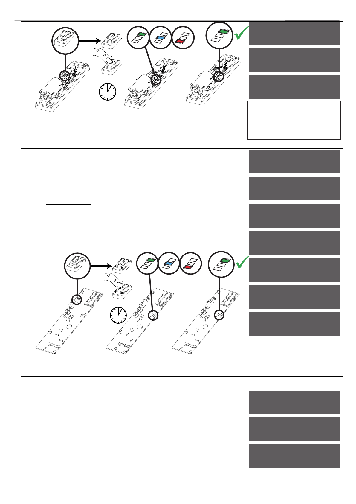
Enforcer: Programming Manual
LEARN
>5s
NOTE: The learn process is the same on all wireless contacts,
detectors, and sensors. Once the GREEN LED flashes, the learn process
has been successful. If the RED LED flashes, repeat the process above
as the learn procedure has not been successful.
Input 01
Available [01]
Learning...
Input Learnt!
IMPORTANT:
For full learning instructions of
each wireless peripheral, please
refer to the manual provided with
the device.
Wireless Device Control Programming: Learning Bells
1. Press or to scroll to 'WIRELESS DEVICE CONTROL'.
Press .
2. 'Control Inputs' will be displayed. Press .
3. 'Control Bells' will be displayed. Press .
4. 'Learn Devices' will be displayed. Press or press to
access the delete menus (you can either delete individual
devices or delete all).
5. Press [ or ] to select the bell (1 or 2) to learn and press
.
6. Open the wireless Deltabell and press and hold the 'LEARN'
button until all LEDs flash then release.
LEARN
>5s
WIRELESS DEVICE
CONTROL?
Control Inputs?
Control Bells?
Learn Devices?
Select Bell
Available [1]
Learning...
Bell Learnt!
NOTE: Once the GREEN LED flashes, the learn process has been
successful. If the RED LED flashes, repeat the process above as the
learn procedure has not been successful.
Wireless Device Control Programming: Program Keyfob Buttons
1. Press or to scroll to 'WIRELESS DEVICE CONTROL'.
Press .
2. 'Control Inputs' will be displayed. Press .
3. 'Control Bells' will be displayed. Press .
4. 'Program Keyfob Buttons' will be displayed. Press .
5. Press [ or ] to select the user (1-80) and press .
6. Press [ or ] to select the button to be programmed and
Page: 8
WIRELESS DEVICE
CONTROL?
Control Inputs?
Control Bells?

Enforcer: Programming Manual
press .
7. Press [ or ] to select the action of the button and press
.
8. Select the area that the keyfob should be programmed in, press
.
NOTE: Keyfobs are learnt in the Master Manager Menu under 'EDIT
USERS'. Refer to the user manual.
NOTE: Using the output types 170-199 (User Defined), outputs can be
activated by the keyfob buttons. Refer to ‘User Outputs’ function in the
‘CHANGE OUTPUTS’ menu.
Program Keyfob
Buttons?
User [01]
Select Button
Lock [1]
Wireless Device Control Programming: Control Arming Stations
1. Press or to scroll to 'WIRELESS DEVICE CONTROL'.
Press .
2. 'Control Inputs' will be displayed. Press .
3. 'Control Bells' will be displayed. Press .
4. 'Control Arming Stations’ will be displayed. Press .
5. 'Learn Devices' will be displayed. Press or press to
access the delete menus (you can either delete individual
devices or delete all).
6. Press [ or ] to select which keypad (1-4) to learn and press
.
7. Open the LEDRKP-WE and
press and hold the 'LEARN'
button until all LEDs flash.
Then release
NOTE 1: Once the GREEN LED
flashes, the learn process has
been successful. If the RED LED
flashes, repeat the process above
as the learn procedure has not
been successful.
NOTE 2: Tags to control setting/unsetting are learnt in the Master Manager Menu under 'EDIT USERS'.
Refer to the user manual.
NOTE 3: Wireless Arming Station’s functions in the 'ASSIGN KEYPADS/READERS function. These are
mapped as:
LEDRKP-WE #1 : Address [4] LEDRKP-WE #2 : Address [5]
LEDRKP-WE #3 : Address [6] LEDRKP-WE #4 : Address [7]
LEARN
BUTTON
WIRELESS DEVICE
CONTROL?
Control Inputs?
Control Bells?
Learn Devices?
Select Arm Stat
Available [1]
3.3 Change Inputs
A total of 66 inputs can be programmed on the Enforcer system. All inputs are unused by default. To
save any programming the Engineer menu must be exited.
Input Types
See Appendix B, page 35 for all input type options.
Most commonly used input types:
[06] Intruder. [07] Final Exit. [08] Entry Route. [13] Day Alarm.
NOTE 1: If an alarm is triggered from an Entry Route input, it will store for 2 seconds before an
alarm is activated. If a Final Exit input is triggered within this time, the system will select entry
time, rather than an intruder alarm.
NOTE 2: Inputs may be automatically omitted at the time of reinstatement, which is at the end
of confirmation time. This is irrelevant of whether the input has the attribute ‘Ommitable’ set to
‘Yes’ or ‘No’
Page: 9

Enforcer: Programming Manual
Input Areas
The Enforcer supports up to 4 areas and can be used as follows:
Area A: All Factory
Area B: Reception Only
Area C: Offices Only
Area D: Factory Floor Only
Input Area (Any/All)
In some installations a ‘common’ area may be required. A common area is an area that only sets
when other specific areas become set. Example: An entry and exit reception area in a building
may only need to be set if both the offices and warehouse are set. If the office in Area A is set,
but the warehouse in Area B is still occupied, then the reception would still need to be inactive so
people would be able to leave the premises via the entry / exit reception route. One input can be
allocated to one or more areas. In this example the inputs located in the reception area will be
programmed so that the reception inputs will be in Area A and Area B, so these inputs must have
the Input Areas set as ‘ALL’ programmed.
Area A: Office - Inputs = 3, 4, 5 Area B: Warehouse - Inputs = 6, 7, 8
Reception inputs – 1 and 2 are programmed into both Areas A and B, with both inputs configured
as ‘ALL’. The Reception Area inputs will now only become active if both Area A and Area B are
both set.
NOTE: All inputs in a common area must be programmed as ‘Entry Route’ or ‘Final Exit’.
Input Attributes
The following attributes can be applied to any input:
Chime: The internal sounder of the Enforcer will sound a chime if enabled. Single: Chimes once
when the input is triggered. Follow: Chimes when the input is triggered and only stops once the
input is inactive. To enable/disable the chime in day mode press , when a 'c' is displayed on
the keypad, the chime is enabled.
Omittable: Enables the input to be manually omitted (disabled) from the setting procedure. To
omit inputs, there is a function in the Master Manager menu called 'OMIT INPUTS'.
Double Knock: The control will only generate an alarm if this input is triggered twice within a
pre-set period, or if the input remains in fault condition for that period.
Normally Open: Enables the system to respond correctly when detectors of ‘normally open’
configuration are wired to the system. Alternatively converts input types which default to
‘normally open’ (e.g. Push to set) to operate with normally closed devices.
Monitor Activity: Enables the input to generate an alarm if the input does not detect any
activity for a period specified by the NAT (Non Activity Time.) See ‘Change Timers’.
Confirm Group: If inputs are selected into the same confirm group, each input will only
generate an unconfirmed alarm (and will not generate a confirmed activation). This is useful
when two or more shock sensors are being activated by the same event. If a confirm group is
selected as ‘00’, the inputs are not part of any group.
Input Description and Location
A name and location can be entered here. The name will appear on the display if an alarm has
occurred; the location is used for a more detailed reference if required.
Change Inputs Programming
1. Press or to scroll to 'CHANGE INPUTS'. Press .
2. Press [ or ] to select the input to program (01-66). Press
.
3. 'Input Type' will be displayed. Press [ or ] to select the
input type or input the shortcut number (see Appendix B, page
35 for all input type options.
4. Press
5. 'Input Areas' will be displayed. Select the Area's to be assigned
to the input and press .
6. ‘Input Areas’ will be still be displayed, but this time the options
are ‘Any’ or ‘All’. Make a selection using then [ or ] then
press
7. 'Input Attributes' will be displayed. If any attributes are needed
Page: 10
CHANGE INPUTS?
Input [01]
Input 01
Input Type [07]
Final Exit
Input Areas
[A ]

Enforcer: Programming Manual
for the input, press and press [ or ] to select between
the attribute enable/disable options and press to go to the
next attribute.
8. ‘Input Description’ will be displayed. Press to enter a name
and location for this device or press to return to input
selection.
9. 'Enter Name' will be displayed. Enter the name of the input and
press . This will be displayed if it is activated or when a
fault occurs.
10. 'Enter Location' will be displayed. Enter the location of the input
and press . This will be displayed if it is activated or when a
fault occurs after the name of the input has been shown.
11. Press [ or ] to select another input to program (01-66) or
press the key to return to the Engineer menu.
Input Areas
Any [0]
Input Attribtes?
Input
Description?
Enter Name
_
Enter Location
_
3.4 Choose Mode
If a Enforcer I/O board or any Zone Expander Module (Input Expanders: ZEMs) are used, the
resistance, EOL mode and response time of the inputs can be programmed.
NOTE: Alarm 4K7, Tamper 2K2 must be selected if wiring double pole to an expander.
EOL Range (End of Line Range)
EOL Range programs the panel to operate with different resistor values
[0] Alarm: 1K, Tamper: 1K. [1] Alarm: 4K7, Tamper: 2K2.
[2] Alarm: 4K7, Tamper: 4K7. [2] Wide range.
EOL mode (Double End of Line (DEOL) or Single End of Line (SEOL))
EOL Mode programs all input expanders to operate as:
[0] Single End of Line (SEOL). [1] Double End of Line (DEOL).
Input Response Time
Input Response time programs the time that an input trigger must be present before the
Enforcer system generates an alarm.
[01]-[30] = 100ms to 3000ms
NOTE: Settings above (>) 400ms do not comply with PD6662/EN50131.
Choose Mode Programming
1. Press or to scroll to 'CHOOSE MODE'. Press
.
2. Press [ or ] to select the 'EOL Range' for all wired
inputs*. Press .
Press [ or ] to select the 'EOL Mode' for all wired
inputs*. Press .
Press [ or ] to select the 'Input Response Mode' for
all wired inputs*. Press to return to the Engineer
Menu.
*
On the I/O board and the expanders
Page: 11
CHOOSE MODE?
EOL Mode
DR [1]
EOL Range
4K7/2K2 [1]

Enforcer: Programming Manual
3.5 Install ZEMs
The Enforcer supports up to 66 inputs. Zone Expander Modules (ZEMS) can be used to expand the
Enforcer to have a further 32 wireless inputs, 32 wired inputs or a combination of both. There are
also 2 inputs that can be used on an I/O Board if connected (refer to installation manual).
ZEM Address
[0] ZEM Address 0 (Inputs 35-42) [1] ZEM Address 1 (Inputs 43-50)
[2] ZEM Address 2 (Inputs 51-58) [3] ZEM Address 3 (Inputs 59-66)
NOTE: Inputs 33 and 34 are taken from the I/O board, these do not need to be addressed.
ZEM Installed
[0] No [1] ZEM8/EURO37R. [2] EURO-ZEM32-WE
Enter Location
The text entered here will be displayed on the LCD display if a fault occurs on the ZEM, so the
ZEM can be easily located or referenced. For example, the location text maybe "ZEM Kitchen",
"ZEM Loft" etc.
Install ZEMS Programming
1. Press or to scroll to 'INSTALL ZEMS'.
Press .
2. Press [ or ] to select the 'ZEM Address' . Press
.
3. Press [ or ] to select the 'ZEM8 or ZEM32-WE'
or No' to 'ZEM Installed'. Press .
4. Enter the location of the ZEM. This is so it is
referenced and will appear on the display if a fault
occurs. Press to return to ZEM addressing.
5. 5. Press to return to the Engineers menu.
INSTALL ZEMS?
ZEM Address
[0]
ZEM Installed
No [0]
Enter Location
_
3.6 Change Outputs
This function programs all output types, Any output type may be programmed to any of the systems
outputs, including any outputs for wireless bells. Outputs must be used within their rated capacity.
Please see the installation manual.
Output Types
Refer to Appendix D, page 37 for all output type options. Most commonly used input types:
[0003] Intruder Any. [0006] Confirmed Any. [0014] Siren Any. [0016] Strobe Any.
[0018] Unconfirmed Any. [0051] Line Fault. [0052] Mains Fail. [1###] Follow Input.
Endstation Outputs
This function programs the Bell, Strobe and PGM output on the I/O board if connected (refer to
installation manual).
ZEM Outputs
If a EURO-ZEM8+ or EURO-ZEM8+PSU has been connected to the Enforcer (Zone Expander
Modules), this function programs the 4 outputs on each expander. The address of the expander
is required before the output programming (refer to installation manual.)
Wireless Bells
At default, any wireless bells learnt to the Enforcer have the two outputs programmed as 'Siren
Any' and 'Strobe Any'. These outputs can be programmed differently if required.
Output Module Outputs
If a EURO-OEM8R8T, or EURO-OEM16R+PSU is connected to the Enforcer, they must be
addressed in this function. All output programming is also done here. A maximum of 1 output
expander can be connected to the Enforcer (refer to installation manual.)
Page: 12

Enforcer: Programming Manual
Change Output Programming
1. Press or to scroll to 'CHANGE OUTPUTS'. Press .
2. 'Endstation Outputs' will be displayed. Press to program
any endstation outputs (on the I/O module if connected), or
press for the next function. Use [ or ] to scroll through
the outputs or the select the shortcut number.
3. 'ZEM Outputs' will be displayed. Press to program any ZEM
outputs (on the EURO-ZEM8+ or EURO-ZEM8+PSU if
connected), or press for the next function.
4. 'Wireless Bells'' will be displayed. Press to program any
wireless output types or press for the next function.
5. 'Output Module Outputs'' will be displayed. Press to
address an output module (EURO-OEM8R8T or EUROOEM16R+PSU if connected) or press for the next function.
6. 'Keypad Outputs' will be displayed. Press to program any
outputs on any additional keypads connected or press for
the next function.
7. 'Reader Outputs' will be displayed. Press to program any
outputs on any readers connected or press to return to the
Engineer menu for the next function.
8. 'User Outputs' will be displayed. User Outputs can be activcated
from the Master Manager Menu, and can also be programmed
to be operated via a keyfob. If required, in the ‘Program Keyfob
Buttons’ in the menu ‘WIRELESS DEVICE CONTROL’ menu and
program the outputs for types 170-199.
CHANGE OUTPUTS?
Endstation
Outputs?
BELL O/P [0014]
Siren Any
ZEM Outputs?
Wireless Bells?
Output Module
Outputs?
User Outputs?
3.7 Assign Keypads/Readers
Any additional keypads or readers must be addressed correctly before enabling them in this function.
The Enforcer keypad is automatically addressed as 0 on initial power up. Refer to installation manual
for more information.
Address
Up to 3 x additional wired keypads or readers may be installed. 4 x wireless arming stations can
also be installed. Address 0 is used for the Enforcer on-board keypad.
NOTE: Each keypad has its own individual menu that programs the key-click volume, tag volume
and master volume. It will address a keypad, show the status of the keypad inputs (if
programmed), force the backlight on or off and the identification number of a tag (once a tag is
presented). The PA/Fire timer can be programmed. This menu also addresses the keypad.
To enter the keypad menu, press and hold the key until ‘SECURITY CODE’ is displayed, and
then enter ‘2000’. This function is also used to address the keypad.
NOTE 2: Wireless arming stations (LEDRKP-WE) are learnt to one the 4 wireless arming station
allocations on the Enforcer. However, are seen as addresses 4-7 in ‘Assign Keypads and Readers’
Type
[0] Keypad. [1] Reader. [2] Not Used.
Reader is
If a reader is installed, the following options can be assigned to the reader:
[0] Set Point: Reader used for setting and unsetting.
[1] Not Used: Reader disabled
[2] Access Control: If an access control system is installed then the reader must be
programmed as this type. The lock open time and door open time can be programmed (in
seconds).
[3] Unset Only: If the Reader is to be used as an unset device only, select this type.
[4] Entry Control: Used to lock/unlock doors. The external or internal reader can have
magnetic locks connected to them. This option is used in conjunction with ‘tag opens doors’ in
'SITE OPTIONS' page: 18. The lock open time and door open time can be programmed (in
seconds).
Page: 13

Enforcer: Programming Manual
Set Point Sets
A “Set Point” means that you can program the keypad / reader to set certain Areas only.
This is used in conjunction with the Areas allocated to a user code.
For example, if a user code is programmed to operate Areas ‘A’ and ‘B’, but the keypad /
reader is only programmed to Set Area ‘A’, then the system will arm only Area ‘A’
Selects the area that the device will be defaulted to.
Set Point Unsets
An “Unset Point” means that you can program the keypad / reader to Unset certain
Areas only. This is used in conjunction with the Areas allocated to a user code.
For example, if a user code is programmed to operate Areas ‘A’ and ‘B’, but the keypad /
reader is only programmed to Unset Area ‘A’, then the system will Unset only Area ‘A’.
Set Point In
The keypad needs to also be told which Areas it is operating “in”. For example, a keypad may
only be needed to operate in Area A, but other code users may use the keypad to quick set
other Areas (such as a cleaner, director, caretaker etc). Therefore if Areas A and B are
selected in the previous options (Arm point sets and unset), but Area A only is selected in
‘Set point in’, then Area B will quick arm once a valid tag/code has been entered. To
program Areas operating with their programmed timer, then the Areas need to be
entered into the “Set Point In” function.
Set Point Description
A name and location can be entered here. The name will appear on the display if an alarm has
occurred, the location is used for a more detailed reference if required. E.g. Name = Entrance
Keypad. Location = Hall
Programming Keypads: Assign Keypads/Readers
1. Press or to scroll to 'ASSIGN KEYPADS/READERS'.
Press .
2. Press [ or ] to select the address. Press .
3. 'Type' will be displayed. Press 0 to select keypad.Press
4. 'Set Point Sets' will be displayed. Select the area(s). Press .
Set Point Unsets' will be displayed. Select the area(s). Press
. 'Set Point In' will be displayed. Select the area(s). Press
.
5. 'Set Point Description' will be displayed. Press to enter the
name and location if required.
6. 'Enter Name' will be displayed. Enter the name of the keypad
and press .
7. 'Enter Location' will be displayed. Enter the location of the
keypad and press .
8. Press [ or ] to select another device address to program
(0-3) or press the key to return to the Engineer menu
Programming Readers for Set Point or Unset Only: Assign
Keypads/Readers
1. Press or to scroll to 'ASSIGN KEYPADS/READERS'.
Press .
2. Press [ or ] to select the address. Press .
3. 'Type' will be displayed. Press 1 to select reader.Press
4. 'Reader is' will be displayed. Press 0 for 'Set Point' or press
1 for 'Unset Only' Press .
5. 'Set Point Sets' will be displayed. Select the area(s). Press .
ASSIGN KEYPADS/
READERS?
Address
[0]
Type
Keypad [0]
Set Point Sets
Set Point
Description?
Enter Location
_
ASSIGN KEYPADS/
READERS?
Address
[1]
Page: 14

Enforcer: Programming Manual
Set Point Unsets' will be displayed. Select the area(s). Press
. 'Set Point In' will be displayed. Select the area(s). Press
.
6. 'Set Point Description' will be displayed. Press to enter the
name and location if required.
7. 'Enter Name' will be displayed. Enter the name of the keypad
and press .
8. 'Enter Location' will be displayed. Enter the location of the
keypad and press .
9. Press [ or ] to select another device address to program
(0-3) or press the key to return to the Engineer menu.
Type
Reader [1]
Reader is [0]
Set Point
Set Point Sets
Set Point
Description?
Programming Readers for Entry Control or Access Control:
Assign Keypads/Readers
ASSIGN KEYPADS/
READERS?
1. Press or to scroll to 'ASSIGN KEYPADS/READERS'.
Press .
2. Press [ or ] to select the address. Press .
3. 'Type' will be displayed. Press 1 to select the reader.Press
4. 'Reader is' will be displayed. Press 2 for 'Access Control' or
press 4 for 'Entry Control' Press .
5. 'Set Point Sets' will be displayed. Select the area(s). Press .
Set Point Unsets' will be displayed. Select the area(s). Press
. 'Set Point In' will be displayed. Select the area(s). Press
.
6. 'Lock Open Time' will be displayed. Enter the Lock Open Time
in seconds and press . (Max 255 seconds).
7. 'Door Open Time' will be displayed. Enter the Door Open Time
in seconds and press . (Max 255 seconds).
8. 'Access Control Description' will be displayed. Press .
9. 'Enter Name' will be displayed. Enter the name of the keypad
and press .
10. 'Enter Location' will be displayed. Enter the location of the
keypad and press .
11. Press [ or ] to select another device address to program
(0-3) or press the key to return to the Engineer menu.
Wireless Arming Station Options
Tag Read Enable: Enables the proximity tag reader on the wireless arming station.
Auto Wakeup: Forces the keypad to automatically wake up when an entry time is initiated.
Supervision: When switched to ‘Yes’ the control panel will supervise the signal of the wireless
arming station.
Back Light: Toggles the LCD backlight on or off.
Entry/Exit Sound: When enabled, the arming station will mimic the entry/exit tones of the
panel.
Set Point Sets: Enter the areas that the arming station is permitted to set.
Set Points Unsets: Enter the areas that the arming station is permitted to unset.
Set Point In: Enter the areas that the arming station is located in.
Set Point Description: Enter a name and location for the arming station.
Address
[1]
Type
Reader [1]
Reader is [4]
Entry Control
Set Point Sets
Lock Open Time
[005]
Door Open Time
[005]
Page: 15

Enforcer: Programming Manual
3.8 Change Timers
This function controls all timers of the Enforcer.
Timers
For a list of all timers, refer to Appendix C, on page 36.
Most commonly used timers:
Entry Time (0-255 seconds), Exit Time (0-255 seconds), Siren Time (2-15 minutes), Confirm
Time (1-99 minutes), Wireless Supervision Time (0-99 hours), App Exit Time (0-199
seconds)
NOTE: The timer for inputs on 'Soak Control' is in the function 'ENGINEER TESTS'.
Change Timers Programming
1. Press or to scroll to 'CHANGE TIMERS'. Press .
2. 'A Entry Time' will be displayed. Enter the time and press .
Refer to Appendix C, page 36 for all timers and enter the time
on the required function and press for the next timer.
3. Press to return to the Engineer menu.
CHANGE TIMERS?
A Entry Time
[030]
3.9 Codes And Users
This function changes the Engineer code, the Master Manager code and adds/changes/deletes any
Duress or Guard codes.
Default Codes: User: None. Master Manager:2222. Engineer: 1111
NOTE: User codes, fobs and keyfobs can only be changed in The Master Manager Menu. Please see
the user manual for more information.
5 Digit Pins?
If enabled, all new codes added to the system will require a miniumum of 5 digits.
PLEASE NOTE: Any existing 4 digit codes will still be valid.
Delete Users And Fobs
This will delete all the key fobs and user codes from the system.
PLEASE NOTE: that this will not delete the Master Manager and the Engineer codes.
Change Duress Codes
[2] Duress Code: If the Enforcer is unset using a 'Duress' code, a silent 'Duress' or 'Hold Up'
signal is sent.
NOTE: ACPO policy prevents use of Duress codes for police call purposes.
[3] Guard Code: A 'Guard code' can be used to unset the Enforcer only after an alarm has been
activated for a minimum time (see 'Change Timer' Appendix C, page 36). The code will set a
system and an output type is available to signal when this code is used (0058 Guard Code).
[4] Dial Out: A dial code is used to force the panel to dial out the UDL software while in ‘Day
Mode’
Change Master Manager Code
The Master Manager code can be 4, 5 or 6 digits long, or can be assigned to a tag. It may also
have the following functions:
[0] Unset / Set. [1] Unset Only. [2] Set Only. [3] None (used only to access the menu).
Flexi Set: If enabled, the default area the device is assigned to, will set. If disabled, the default
area will be shown on the display, and from here other areas can be selected.
Wards/Access: This will only be displayed if an Entry Control or Access Control reader is
installed on the system. If the address of the Entry Control or Access Control device is entered
here, then the code will be assigned to that reader only.
Change Engineer Code
The Engineer code can be 4, 5 or 6 digits long.
Page: 16

Enforcer: Programming Manual
Change Codes Programming
1. Press or to scroll to 'CODES AND USERS'. Press .
2. '5 Digit Pins' will be displayed. Press [ or ] to enable or
disable and press .
3. 'Change Duress Codes' will be displayed. Press to add any
Duress, Guard or Dial out codes (as described previously) or
press .
4. 'Change Master Manager Code' will be displayed. Press to
change the Master Manager code or press .
5. 'Change Engineer Code' will be displayed. Press to change
the Engineer code or press to return to the Engineer menu.
CHANGE CODES?
5 Digit Pins?
No [0]
Change Duress
Codes?
3.10 Volume Control
The Volume Control function applies to the loudspeaker output only. Volume levels at the keypad are
programmed individually – refer to page: 13 on how to access the menu.
Volume Controls
The following volume on each sound can be controlled: Entry, Exit, APP Exit, Alarm, Fire,
Tamper, Day alarm, and Chime.
PLEASE NOTE: App exit volume overrides other exit volumes when setting using the
HomeControl+ app.
Volume controls: 0 = Completely silent. 1 = Silent but sounds a beep when the system is set
2-7 volume of tones (7 = loudest).
Code Stops Sound
If this function is enabled, then once an alarm has been generated (even if the code is not
programmed for that area) the alarm will be silenced, and a ‘Misoperation (Abort) signal’ will be
sent. The area will remain set until a code or tag is presented that is assigned to that area.
Entry/Exit Keypads Only
If this function is disabled, any entry and exit tones will be heard through the main sounder. If
enabled, the entry and exit tones will only be heard through the keypad speaker.
Alert Kps Only
If this function is enabled, any 'Alert' tones will be heard on the Keypad only and not the main
sounder. If disabled, the alert tones will heard through both.
Silent Technical Alert
If this function is enabled then any technical alerts will be silenced, e.g line fault, ARC call fail.
Use Main Sounder
If enabled, all volumes that are programmed as will activate on the main sounder. If disabled,
the sounder will only activate on activations programed on volume 6-7.
Volume Control Programming
1. Press or to scroll to 'VOLUME CONTROL'. Press .
2. 'A Entry' will be displayed. Enter the volume and press .
Repeat for all areas.
3. 'Code Stops Sound' will be displayed. Press [ or ] to enable
or disable and press .
4. 'E/E Keypads Only' will be displayed. Press [ or ] to enable
or disable and press .
5. 'Alert Kps Only' will be displayed. Press [ or ] to enable or
disable and press .
6. 'Silent Tech Alert' will be displayed. Press [ or ] to enable
or disable and press .
7. 'Use Main Sounder' will be displayed. Press [ or ] to enable
or disable and press . The Engineer menu will be displayed.
VOLUME CONTROL?
A Entry
[0]
Code Stops Sound
No [0]
E/E Keypads Only
No [0]
Page: 17

Enforcer: Programming Manual
3.11 System Options
3.11.1 Site Options
A full range of site options is available to tailor the operation of the system.
Set with Fault:
If 'YES', the Enforcer will set regardless of the following faults being present: device fail, mains
fail, battery fault, fuse fault.
Set with Tamper:
If 'YES', the Enforcer will set regardless of any input tampers.
Set with ATS Fault:
If 'YES', the Enforcer will set regardless of the following ATS faults being present: telecom line
fail, modem fail, ATE path fail, Digi dial fail, or comms fail.
Set Fail = Alarm:
If 'YES', the Enforcer will generate a graduated alarm when the 'Set Fail' timer has expired (See
'CHANGE TIMERS', page: 15), and will trigger any output programmed as '0011 Set Fail' if the
setting procedure is still incomplete. If 'NO' the exit timer will continue until the exit route is
clear.
Do Battery Load Test:
If 'YES', the Enforcer will perform a full battery load test at 7:00am each day.
Strobe/Squawk at Set:
If 'STROBE', any output programmed as 'STROBE ANY' will activate for 5 seconds after the
Enforcer has set. If 'SQUAWK' any output programmed as 'SIREN ANY' will activate for 5 seconds
after the Enforcer has set, and if 'BOTH' then any outputs programmed as STROBE ANY or SIREN
ANY will activate for 5 seconds after the Enforcer has set.
NOTE: If this function is enabled, a potential security risk could be in view for intruders to see.
Use Level Set
If ‘YES’: The system becomes a ‘level set’ (Having one area set only at any one time). If ‘NO’:
The system becomes an ‘area’ system (setting more than once area at a time).
Autoset Force:
If 'YES', and an auto set timer is programmed on the InSite upload/download software, then the
Enforcer will set on an auto set regardless of any inputs being open during the setting period.
Restrict PIN use:
If 'YES', the Enforcer prevents a PIN code being entered on the Entry time, but allows a PIN code
to silence any alarm that may occur.
NOTE: Enable when BS8243 option 6.4.5 is in use
Simple Set
If 'YES', the Enforcer allows a user to set the system 'quickly' by pressing and then the Area
(A, B, C or D).
NOTE: This must not be enabled when BS8243 option 6.4.5 is in use.
Intelligent Set
The system has the facility to automatically initiate a different set mode or area when you
activate an input in a certain area (rather than having to choose a different Set mode via the
keypad). This is known as “Intelligent Setting”.
Please note that when Intelligent Setting has been enabled the exit tone will commence at
‘intelligent’ volume. When intelligent set is enabled, then level set B will start to set (if the user
code is enabled in level set B). Then if a Final Exit input is activated, which is programmed in
level set A during the exit time, then the panel will automatically ‘quick set’ in level set A.
NOTE: Intelligent Set only works when the panel is in Level Set mode. (See Site Options)
Page: 18

Enforcer: Programming Manual
Common Lobby
If ‘Yes’, this will automatically prioritise the exit modes for each area:
(0 = Timed, 1 = Final Door, 2 = Timed/Final Door, 3 = PTS). This option is only relevant when
Final Door option is used on a system with different areas using a common lobby.
EXAMPLE: If Area C is selected as the ‘Final Door’ setting mode and the rest of the areas are
selected as ‘Timed’, then because ‘Final Door’ is higher priority, the users of every individual area
must follow the ‘Final Door’ route to the exit - making this door a ‘common for all areas’. If set to
‘NO’ the exit modes will be individually programmable to each area.
Flexi Unset
When enabled, this setting will allow users to select which areas they unset (from the
areas that they have been permitted to unset.)
2 Key HU:
If the 1 and 7 keys are pressed and held together for a period of time (programmed in the
keypad menu, see page: 13), a 'Hold Up' will occur.
If 'NONE', the keys are disabled. If 'SILENT', a 'Silent Hold Up' will be signaled. If 'Bells Only',
any external sounder will activate but NO signals will be sent. If 'BOTH', any external sounder
will activate and a signal will be sent using a Digi 1200 (PSTN),Digi-1200/Voice Digi GPRS, Digi
LAN or Digi Wi-Fi module.
Tag Opens Doors
This function is only be used in conjunction with a reader being programmed as 'Entry Control' is
in 'ASSIGN KEYPADS/READERS' (see page: 12).
If 'YES' the 'Entry Control' readers will control the setting/unsetting and the doors. If 'NO' the
Entry Control readers will control the setting/unsetting only.
Fire Key Enable
If 'YES' the fire key will be enabled on the Enforcer keypad.
Set With Polling Fault
If ‘YES’ the Enforcer will set the system if there is a wireless polling fault.
If 'NO' the user will not be able to set the Enforcer with a polling fault. The Enforcer will display a
fault and the arming procedure will be stopped. The input causing the poll fault can be identified
in the event log.
Fob Unset Entry
If 'YES' any wireless keyfobs learnt will only be able to unset the Enforcer once the entry time
time has been activated. If ‘NO’ any wireless keyfobs learnt will always be able to set and unset
the Enforcer.
Wireless Bell Supervision
If 'YES' then the wireless external sounder (DELTABELL-WE) will go into alarm if it can no longer
communicate with the Enforcer.
Download if Set
If 'YES' any upload/download procedures will be possible on the InSite software regardless of the
set/unset status of the Enforcer.
UDL or Cloud Priority
By default this is set to ‘high’ meaning that UDL or Cloud signalling will take priority over ARC
signalling events to maintain a smooth cloud connection. If the system is graded then this setting
will default to ‘low’ so that UDL or Cloud connections cannot delay ARC signalling events.
Site Options Programming
1. Press or to scroll to 'SITE OPTIONS'. Press .
2. 'Set With Fault' will be displayed. Use [ or ] to
enable/disable each option and press . Repeat for all
functions. The engineer menu will be displayed once all
functions have finished.
SITE OPTIONS?
Set With Fault
Yes [1]
Page: 19

Enforcer: Programming Manual
3.11.2 System Displays
This function programs the text display on the keypad for when the system is unset, or an area is
set. The Site Name reference is programmed here which must match the site name programmed
on the InSite software. There are options to enable or disable displaying when set, alarms, hold
ups or inputs.
Area Texts
This programs how each Area will be displayed. For example if 'Area A' is used to set the full
house this can be text as “Full House Set”. There is a maximum of 16 characters on the display.
Sign On Message
The Sign on Message is the main display on the top line in unset mode.
Display When Set / Display Alarms / Display HU’s (Not Compliant)
If ‘Display when set’ is enabled, then the Area Text will be displayed on the LCD keypad once the
system is fully set. If Display Alarms / HU’s are enabled, they will show any alarms that are
activated before a valid user code/tag is entered. If Display Inputs is enabled, any inputs
activated in day mode will be displayed.
System Displays Programming
1. Press or to scroll to 'SYSTEM DISPLAYS'. Press .
2. 'Area A Text' will be displayed. Enter the text and press .
Repeat for all areas.
3. 'Sign on Message' will be displayed. Enter the text and press
.
4. 'Display When Set' will be displayed. Press [ or ] to enable
or disable the function. Press . Repeat for 'Display Alarms',
'Display Hold Ups', and 'Display Inputs'. Press to return to
the Engineer menu.
3.11.3 Exit Modes
The ‘Exit Modes’ operate the Setting procedure of the Enforcer system. The following Exit Modes
are available:
Exit Modes
[0] Timed: The Enforcer system will set when the programmed 'Exit Time' has expired (See
‘Change Timers’ on page 16).
NOTE: This is NOT suitable for systems installed to comply with BS8243.
[1] Final Door: The Enforcer system will set when an input programmed as 'Final Exit' is either
closed (if the input was opened when setting started) or it is opened and closed. 'Final door' is
used for the ‘lock set’ operation; securing the lock completes the setting procedure and unlocking
starts the entry time.
[2] Timed/Final: The Enforcer system will set when a 'Final Exit' input has been closed, or
when an 'Exit Time' has expired. The 'Final Exit' input will override any 'Exit Time' programmed if
opened/closed.
NOTE: This is NOT suitable for systems installed to comply with BS8243.
[3] Push to Set (PTS): The Enforcer system will only Set when a ‘Push to Set’ button has been
pressed. This function will override the programmed Exit Time.
SYSTEM DISPLAYS?
Area A Text
Full Set
Sign On Message
Enforcer
Exit Modes Programming
1. Press or to scroll to 'EXIT MODES'. Press .
2. 'A Exit Mode' will be displayed. Press [ or ] to select the
Exit Mode and press . Repeat for all areas.
3. Press to return to the Engineer menu.
EXIT MODES?
A Exit Mode
Final Door [1]
Page: 20

Enforcer: Programming Manual
3.12 Review Logs
The control panel has two Event Logs, which are time and date stamped. The first log which is a
panel log, records all events that occur on the Enforcer, i.e. Users entering their codes to set or unset
areas, alarm events, failures to arm etc.
The second log which is an access log, only records access control events.
Panel Log
The Panel log records all events that occur on the Enforcer, i.e. Users entering their codes to set
or unset areas, alarm events, failures to set etc. Pressing will give more information of the
display (for example, shows which user unset the Enforcer).
Access Log
The Access log records all events for Access Control events.
With each log, use the key to move from one event to the previous event. The key will
move from one event to the next event that occurred.
To view additional details, press the key. If no other information is available, the display will
move to the next log entry. Pressing the key will return to the main screen for that entry.
NOTE: For all ‘Fault Codes’ please refer to Appendix E, on page 40.
Review Logs Programming
1. Press or to scroll to 'REVIEW LOGS'. Press .
2. 'Panel log' will be displayed. Press to display the panel log.
3. The time, date and event will be displayed. Use [ or ] to
scroll through the event log. If more information is required, for
example, if 'Alarm on Input' is displayed, press to show
more information (e.g. the input that activated). Press to
exit the Panel log.
4. 'Access log' will be displayed. Press to display the access
log and repeat the operations mentioned above. Press to
exit to the Engineer menu.
REVIEW LOGS?
Panel log?
28/04 12:47:49
Engineer Access
Access log?
3.13 Engineer Tests
The Test function allows the engineer to test inputs, outputs, batteries and the siren.
Sounds To Play
This function previews all of the different tones the Enforcer system makes. They have a choice
of: Chime, Chime Follow, Exit, Exit Fault, Entry, Tech Fault, Tamper, Alarm, PA, and Fire.
Walk Test
The walk test feature is used to test all the inputs programmed on the Enforcer. It is
recommended that after programming any inputs, the Engineer menu is exited to save all data,
after this point a walk test should be performed. The inputs that haven’t been activated will be
shown on the display. Once all the inputs have been walk tested, ‘Walk Test Completed’ will be
displayed. When walk-testing a double-knock detector, it must be triggered twice within the
preset period. When testing dual-trip detectors, the first detector must be triggered and then the
second detector; next, trigger the second detector and trigger the first detector.
NOTE: If a just a specific input needs to be walk tested, press instead of selecting areas.
This will then allow specific inputs to be entered with the numerical keys, pressing after each
input. Then press to walk test them.
Soak Control
Any input may be placed on ‘soak test’ which monitors the detector without giving an alarm
activation. If the chosen input triggers whilst the system is set, it will indicate the activation and
enter the details in the event log. The number of days the input is in soak control before the
input becomes active can be programmed.
PLEASE NOTE: The ‘Initial Soak’ time should be set to equal or greater than the ‘Soak Days
Left.’
Page: 21

Enforcer: Programming Manual
Test Siren
Any outputs programmed as '0014 Siren Any' and '0016 Strobe Any' will be tested.
Do Battery Load Test
The Enforcer performs a check of the battery operation every 10 seconds, by dipping the power
supply voltage momentarily, and measuring the system voltage. If the battery voltage measured
is below 8.9V, or the battery fuse has failed, a ‘BATTERY FAULT’ warning will be generated. The
Enforcer is programmed to perform an automatic battery load test at every power supply at
7.00am each day. This will drop the power supply voltage below the battery voltage, whilst
monitoring the system diagnostics. The test will NOT take place if:
The siren and strobe outputs are live
The Enforcer is in Engineer Mode
Any battery or mains faults exists
The site option 'Do Battery Load Test' is not selected (see SystemOptions->Site Options).
If the test has already started, it will be aborted if any of these conditions apply, other than entry
into Engineer Mode. If the test is aborted, it will NOT be performed until the next day. This is
selected in SITE OPTIONS under “Do Battery Load Test”. The test may also be performed as
required, under engineer control.
Test Outputs
The engineer can test all the programmable outputs on the Input/Outboard board and the output
module.
Test Communications
If the engineer is using SIA or Contact ID to signal events, this function can be used to send a
test signal to the Alarm Receiving Centre. It can also be used to test SMS signaling.
Fetch Time
This function is used to manually request the time from the cloud server if it hasn’t updated
automatically. NOTE: This will only be visible with an app compatible modem inserted.
Engineer Tests Programming: Walk Test
PLEASE NOTE: Wireless detectors make take up to 5 minutes to
become active in a walk test.
1. Press or to scroll to 'ENGINEER TESTS'. Press .
2. 'Sound to play' will be displayed. Use [ or ] to select the
different sounds. Press to exit.
3. 'Walk Test' will be displayed. Press .
4. Select the areas that are required to be walk tested and press
or press to walk test individual inputs.
5. A list of all inputs programmed for that area will be displayed
on the keypad. Once an input has been walk tested (i.e. the
detector has activated and deactivated) then the input will be
taken off the list.
6. Once all inputs have been tested, 'Walk Test Completed' will be
displayed. To exit the walk test function at any time press .
7. Press again to go back to the Engineer menu.
ENGINEER TESTS?
Sound to play
No Sound [00]
Walk Test?
Walk Test Areas
[ABCD]
Walk Test Inputs
Input 01
Page: 22

Enforcer: Programming Manual
Engineer Tests Programming: Soak Control
1. Press or to scroll to 'ENGINEER TESTS'. Press .
2. 'Sound to play' will be displayed. Press .
3. 'Walk Test' will be displayed. Press .
4. 'Soak Control' will be displayed. Press .
5. Select the inputs that are required to be soak tested. Each input
should be entered, following by . Press once finished.
6. 'Soak Days Left' will be displayed. Select the number of days
that the inputs will be left on soak test and press .
7. 'Initial Soak' will be displayed. Enter the number of days the
soak test will revert to in the event a soak input is triggered
during testing. Press .
8. Press to go back to the Engineer menu.
Engineer Tests Programming: Test Siren, Battery Load Test and
Test Outputs
1. Press or to scroll to 'ENGINEER TESTS'. Press .
2. 'Sound to play' will be displayed. Press
3. 'Walk Test' will be displayed. Press
4. 'Soak Test' will be displayed. Press
5. 'Test Siren' will be displayed. Press , any outputs
programmed as 'Siren Any' and 'Strobe Any' will trigger. Press
to exit.
6. 'Do Battery Load Test' will be displayed. Press to perform a
battery load test, the voltage will be displayed, followed by
'Battery Passed' if the test has been successful. Press .
7. 'Test Outputs' will be displayed. Press to perform a test on
any output type. For example if '0006' is entered, and the
key is pressed, a 'Confirmed Any' test will be activated. Press
to cancel the test.
8. Press to go back to the Engineer menu.
ENGINEER TESTS?
Sound to play
No Sound [00]
Soak Control?
Soak Inputs [--]
Soak Days Left
[00]
Initial Soak
[00]
ENGINEER TESTS?
Test Siren?
Testing Siren...
Do Battery Load
Test?
Testing Battery
13.3V
Test Outputs?
OP Test [0000]
Page: 23

Enforcer: Programming Manual
Engineer Tests Programming: Test Communications
1. Press or to scroll to 'ENGINEER TESTS'. Press .
2. 'Sound to play' will be displayed. Press .
3. 'Walk Test' will be displayed. Press .
4. 'Soak Test' will be displayed. Press .
5. 'Test Siren' will be displayed. Press .
6. 'Do Battery Load Test' will be displayed. Press .
7. 'Test Outputs' will be displayed. Press .
8. 'Test Communications' will be displayed. Press to send a
test signal to the ARC.
9. Press to go back to the Engineer menu.
ENGINEER TESTS?
Test
Communications?
Are You Sure?
3.14 Diagnostics
This option enables the engineer to perform full diagnostics on all key wired and wireless components
of the system.
Wireless Devices
View Inputs:
This option views the status of all wireless inputs: O=Open, C=Closed, T=Tamper, F=Fault,
S=Supervision fault and B=Battery fault.
View Inputs / Bells / Arming Station Signal Strength:
This option is used to view the signal strength for any wireless input, bell or arming station that
is learnt to the HomeControl+ system. The signal strength is shown on both the individual
wireless device and on the HomeControl+ Panel in the following ways:
If a Green LED is shown the signal strength is HIGH.
If a Red LED is shown the signal strength is LOW / NONE.
Once one of the signal strength menus has been entered, ‘Please Wait’ will be displayed and a
countdown from 300 seconds will begin. This may last up to five minutes before all of the
wireless devices have been analysed. From this point each device is tested every 15 seconds. On
the LCD display it is also possible to view each individual device’s signal strength as a
percentage.
3 = Excellent signal – Shows GREEN on the wireless Device / 80 to 100%
2 = Good signal – Shows GREEN on the wireless Device / between 30 to 80%
1 = Weak signal – Shows RED on the wireless Device / between 10 to 30%
0 = Missing – Shows RED on the wireless Device / between 0 to 10%
‘?’ = Waiting for device signal strength information
View Inputs / Bells/ Arming Stations - Battery Status:
This option is used to measure the battery levels for wireless inputs and bells. The battery level
is shown on the control panel.
Once the battery status menu has been entered, ‘Please Wait’ will be displayed and a countdown
from 300 seconds will begin. This may last up to five minutes before all of the wireless devices
have been analysed. From this point each device is tested every 15 seconds.
Testing = Waiting for a Battery result
Good = At least one month of battery life remaining
Replace = Battery needs to be replaced immediately
Wireless Dual Frequency Menu
This option shows information on whether the panel/wireless ZEM are working as a Single or
Dual Frequency system. It will also display which inputs (if any) are single frequency and
stopping the panel from operating in dual frequency mode.
Page: 24

Enforcer: Programming Manual
Wired Devices?
View Inputs
This option views the status of all wired inputs: Open, Close, Tamper, and Fault.
Endstation Inputs: The status of the inputs will be shown. C = Closed. O = Open. F = Fault, T
= Tamper. The resistance reading can also be shown by pressing
for any of the above for
statuses.
ZEM Inputs: Choose the ZEM ID from [0] to [3] to view the input status.
View PSUs?
This option allows diagnostics of the power supply information for the PSU on the control panel,
as well as all the additional peripheral devices, such as ZEM or Output modules that have a PSU
on board.
Endstation PSU: End station voltage readings are displayed = Voltage: 13.7V.
ZEM PSUs: Choose the ZEM ID from [0] to [3] to read the PSU voltage readings.
OP Mod PSU: Choose the Output Module ID to read the PSU voltage readings.
Keypad Volts: Choose the Keypad ID from [1] to [3] to read the keypad voltage.
Reader Volts: Choose the Reader ID from [1] to [3] to read the reader voltage.
Communications
This function displays the information gathered from the communication device currently fitted.
GPRS Module:
GPRS Signal Strength: The range ‘0-31’ indicates the signal (31 = Excellent. >10 = Poor).
‘--.-- ‘ indicates no signal.
App or ARC Status messages: Displays the current connection status of the PyronixCloud.
Initialising – The panel is attempting to connect to the mobile network
No Network – There is no network available
Basic Network – The GSM network is available
Full Network – The panel is logged onto the GPRS network
Polling Cloud (App only) – The panel is polling the cloud
Polling ARC (ARC only) – The panel is polling the ARC
Last App Contact: Displays the time period since the last successful connection to the
HomeControl+ App.
Last Polled Cloud: Displays the time period since the last successful poll to the PyronixCloud.
Last Polled ARC: Displays the time since the last successful poll to the ARC.
LAN or WiFi Module:
(Wi-Fi Only) Signal Strength: The range ‘0-31’ indicates the signal
(31 = Excellent. >10 = Poor). ‘No Signal ‘ indicates no signal.
IP Address: Displays the IP address of the LAN Module (if installed).
Subnet Mask: Displays the Subnet Mask of the LAN Module (if installed).
Gateway: Displays the IP address of the Gateway.
App or ARC Status messages: Displays the current connection status of the PyronixCloud.
Initialising – The panel is attempting to connect to the network
No Network – There is no network available
Polling Cloud (App only) – The panel is polling the cloud
Polling ARC (ARC only) – The panel is polling the ARC
Last App Contact: The time period since the last successful connection to the HomeControl+
App.
Last Polled Cloud: The time period since the last successful poll to the PyronixCloud.
Last Polled ARC: The time since the last successful poll to the ARC.
PSTN and PSTN/VOICE Modem:
This will display the PSTN line status of whether there is a line present or missing.
GSM Modem
GSM Signal Strength: The range ‘0-31’ indicates the signal (31 = Excellent. >15 = Poor).
‘--.-- ‘ indicates no signal.
Page: 25

Enforcer: Programming Manual
Diagnostics Programming: Wireless Devices.
1. Press or to scroll to 'DIAGNOSTICS'. Press .
2. 'Wireless Devices':. Press .
3. 'View Inputs’: To view each input status, press .
4. Use [ and ] to choose which inputs to view. Press .
5. The status of each input will be shown:
6. O=Open, C=Closed, T=Tamper, and F=Fault.
7. Press twice to exit, and again for the next sub-menu
item.
8. 'View Input Signal Strength’: To view each inputs signal
strength press .
9. Use [ and ] to choose which inputs to view. Press .
10. The status of each input will be shown:
3 = Excellent signal – Shows GREEN on the wireless Device
/ 80 to 100%.
2 = Good signal – Shows GREEN on the wireless Device /
between 30 to 80%.
1 = Weak signal – Shows RED on the wireless Device /
between 10 to 30%.
0 = Missing – Shows RED on the wireless Device / between
0 to 10%.
‘?’ = Waiting for device signal strength information.
11. Press twice to exit, and again for the next sub-menu
item.
12. Repeat the above for ‘View Bells Signal Strength’, and ‘View
Arming Station Signal Strength’.
13. 'View Inputs Battery Status':. Press .
14. Use [ and ] to choose which inputs to view. Press .
15. The status of each input will be shown:
Testing = Waiting for a Battery result
Good = At least one month of battery life remaining
Replace = Battery needs to be replaced immediately
16. Press twice to exit, and again for the next sub-menu
item.
17. Repeat the above for ‘View Bells Battery Status’, and ‘View
Arming Station Battery Status’
18. 'Wireless Dual Frequency Menu':. To view Dual Frequency
menu information. Press .
19. Press to exit.
DIAGNOSTICS?
Wireless Devices
View Inputs?
Wrlss Inputs [2]
Endstation 1-32
OOCOC-----------
----------------
View Input
Signal Strength?
Wrlss Inputs [2]
Endstation 1-32
33333-----------
----------------
View Inputs
Battery Status?
Wrlss Inputs [2]
Endstation 1-32
Input [01]
Good
Wireless Dual
Frequency Menu?
Diagnostics Programming: Wired Devices.
1. Press or to scroll to 'DIAGNOSTICS'. Press .
2. Press until 'Wired Devices' is displayed:. Press .
3. 'View Inputs’: To view each input status, press .
4. ‘Endstation Inputs’: To view each input status on the I/O
board, press .
5. The status of each input will be shown:
6. O=Open, C=Closed, T=Tamper, and F=Fault. Press again
to view each input individually, and the resistor readings.
7. Press twice to exit, and again for the next sub-menu
item.
8. Repeat the above for ‘ZEM Inputs’.
9. ‘View PSUs’: To view the power supply information press .
10. ‘Endstation PSUs’: The voltage will be displayed. Press .
Page: 26
DIAGNOSTICS?
Wired Devices
View Inputs?
Endstation
Inputs?

Press to view the power supply information for ZEMs,
Output Modules, Keypads and readers.
11. Press twice to exit.
Enforcer: Programming Manual
00
View PSUs?
Diagnostics Programming: Communications.
1. Press or to scroll to 'DIAGNOSTICS'. Press .
2. Press until ‘Communications: is displayed. Press .
3. See the ‘Modem and Communication Guide’ for more
information.
Communications?
3.15 Engineer Reset Options
The Engineer Reset Options are used so that once an alarm has occurred; the Enforcer system can
only be reset by an engineer code or anti-code.
Engineer Restore of Intruder
If 'UK Intruder', an Engineer code must be used to reset the Enforcer after an alarm. 'Secure
Intruder' should not be used.
Engineer Restore of Hold Up
If 'YES', an Engineer code must be used to reset the Enforcer after an Hold Up, Input Hold Up, or
Duress activation.
Engineer Restore of Tamper
If 'YES', an Engineer code must be used to reset the Enforcer after a tamper activation.
Engineer Restore of Soak
If 'YES', an Engineer code must be used to reset the Enforcer after an input that is on 'soak' has
triggered when the Enforcer is set.
Engineer Restore of Confirmed
If 'YES', an Engineer code must be used to reset the Enforcer after a confirmed alarm has
occurred.
Engineer Restore of Faults
If 'YES', an Engineer code must be used to reset the Enforcer after the following faults: ATE
telecom fail, Modem fail, ATE single path fail, Telecom line fail, Battery disconnect, Batt charge,
Battery load, Excessive charge, Battery critical and Device fail.
Anti-Code Restore
If 'YES', the Enforcer will display an Anti-Code, to which can be used to generate a special reset
code (usually from the ARC) to reset the Enforcer.
NOTE: that if Anti-Code is selected, this will coincide with the options that have been selected
previously. For example, if ‘Engineer Restore Intruder’ is selected, and Anti-Code is selected,
then an anti-code will be produced on intruder activation.
Engineer Reset Options Programming
1. Press or to scroll to 'SITE OPTIONS'. Press .
2. 'Engineer Restore Intruder' will be displayed. Use [ or ] to
enable/disable each option and press . Repeat for all
functions. The engineer menu will be displayed once all
functions have finished.
ENGINEER RESTORE
OPTIONS?
Eng Restore Int
No [0]
Page: 27

Enforcer: Programming Manual
3.16 Alarm Response
The Alarm Response function controls how certain activations are to perform.
Silent 1st Alarm
If this function is selected as ‘confirmed’, then the first alarm to activate on the system will be
silent, but only if another input activates (i.e. a confirmed alarm) then the alarm will activate and
the alarm tones will be heard. This option is only valid once the system has been set for 3
minutes and not if the entry time has started.
Disable Confirm On Entry
To comply with BS8243 clauses 6.4.3 and 6.4.4, this option should be set to YES to disable
confirmation once the entry procedure has started. For use with BS8243 option 6.4.5, this
option should be ‘No’. If ‘Disable Confirm On Entry’ is set to YES this option will disable ALL
confirmation signals on entry. If NO the confirmation signals are enabled on expiry of entry time.
Alarm Starts / Stops (Alarm Responses)
There are 4 different 'Alarm Responses' that can be programmed:
[0] Keypads: If an alarm occurs, the keypad sounder will activate.
[1] Internal Sounders: If an alarm occurs, the internal sounder will activate.
[2] Bells Only: If an alarm occurs, the external sounders will activate.
[3] Signal Digi: If an alarm occurs, the digi will communicate.
[4] Confirm: If an confirmed alarm occurs.
If the Alarm Response for Area A is programmed as 'Start At' "Keypads" and 'Stop at' "Bells
Only" then it will take 15 seconds to go through each alarm responses before stopping at "Bells
Only".
If the Alarm Response is programmed as 'Start At' "Signal Digi" and 'Stop At' "Confirm", all
keypads, internal sounders and bells only will activate the same time as 'Signal Digi' and all will
stop when there is a 'Confirmed Alarm'.
The Enforcer can operate on a combined Area basis, for example if both Areas ‘A’ and ‘B’ are set;
you may want the process of the alarm responses to change. Therefore The ‘If Areas set’ section
of this function should be used and select the desired Areas and the Alarm Responses.
Alarm Responses Programming
1. Press or to scroll to 'ALARM RESPONSES'. Press .
2. 'Silent 1st Alarm' will be displayed. Press [ or ] to enable or
disable and press .
3. 'Disable Confirm on Entry' will be displayed. Press [ or ] to
enable or disable and press .
4. 'Area A start at' will be displayed. Press [ or ] to select the
alarm responses and press . Repeat for all alarm notifications.
5. The Engineer menu will be displayed.
ALARM RESPONSE?
Silent 1st Alarm
Never [0]
Disable Confirm
On Entry. No [0]
3.17 Set Up Downloading
If required, the Enforcer can be programmed remotely, or directly via a PC/Laptop.
To upload/download remotely, a communications module must be installed.
To upload/download directly, an RS232 must be used and connected directly to the Enforcer.
Set Up Downloading Programming: Cloud
1. Press or to scroll to 'SET UP DOWNLOADING?'. Press
.
2. 'Download By' : Use [ or ] to scroll to ‘Cloud’. Press .
3. The SYSTEM ID will be displayed will be displayed. Press .
4. Use [ or ] to select either Normal or High Security Level.
NOTE: If High is selected, encrypted keys will need to be created.
Press .
5. Enter a System Password. Press (NOTE: This is required)
SET UP
DOWNLOADING?
Download by
Cloud [6]
SYSTEM ID
AAABBBCCC
Page: 28

Enforcer: Programming Manual
6. Always Poll Cloud’ - use the [ and ] keys to enable/disable
polling to the cloud. Press (Recommended to ‘Yes’)
7. Roving Dial - use the [ and ] keys to enable/disable roving dial
8. UDL Password – if the UDL software that the panel is connecting to
has a password, use the numerical keys to enter it here. Press
9. Site Name – Using the numberal keys to enter the site name from
‘System Displays’ Press
PLEASE NOTE: Make sure that the SIM card in use is enabled for
GPRS data and that the correct APN settings have been entered for
your network (See ‘COMMUNICATIONS’).
Connecting to the InSite software:
1. Click on ‘Roving Dial customer’ (or hold Ctrl and press the F10 key).
2. Click on the ‘Dial Out Mode’ drop down list and select ‘Cloud’
3. Enter the ‘System ID’ of your Control Panel (See ‘Set Up Downloading’ in the panel’s Engineer
menu)
4. Enter the ‘System Password’ (as entered in ‘Set Up Downloading’ in the Engineer menu)
5. Leave the UDL security level at ‘low’ for the initial connection test in the ‘System Security Level’
field.
6. Enter the Engineer code as used on the Control Panel you are trying to connect to.
7. Enter the ‘Site Name’ as entered in the panel ONLY if it was entered on the panel, to otherwise,
leave this blank.
8. In the ‘Enter Customer In Database As’ field, simply give the panel you are connecting to an
appropriate name.
9. Click ‘Dial’. If the connection is successful, the Cloud Icon will become blue. A dialogue box will
appear asking if you would like to create a customer, click ‘yes’ to continue.
The system is now successfully connected to the Insite UDL Software. Now select ‘Data from Panel’ to
download panel settings and proceed to make changes remotely.
Security Level
Normal [0]
System Password
_
Alwys Poll Cloud
No [0]
Set Up Downloading Programming: RS232
1. Press or to scroll to 'SET UP DOWNLOADING?'. Press
.
2. 'Download By' : Use [ or ] to scroll to ‘RS232’. Press .
3. Enter a UDL password. This will need to be referenced in the InSite
software. Press .
4. Enter a Site Name. This will need to be referenced in the InSite
software. Press .
PLEASE NOTE: If a Site Name is set up on the panel, the UDL Site
Name must be exactly the same, otherwise the connection will fail.
SET UP
DOWNLOADING?
Download by
RS232 [2]
UDL Password
_
SIte Name
_
Connecting to the InSite software:
1. To set up the COM port associated to ‘modem’, open the software, click on ‘Configuration’, choose
‘Modem Settings’ and select the ‘RS-232’ option
2. Make sure that the serial COM used by the UDL software is set the same as in youR PC.
3. e.g. Control Panel -> Device Manager -> Ports (Typical Windows PC)
4. Make sure that the RS-232 icon (at the bottom of the screen) has turned green
5. Click on ‘Roving Dial customer’ (or hold Ctrl and press the F10 key).
6. Set the ‘Dial Out Mode’ field to ‘RS-232’
7. Enter the Engineer code in the ‘Engineer Code’ field
8. Enter the ‘Site Name’ if one has been put in the panel in ‘System Displays’
9. In the ‘Enter Customer In Database As’ field, simply give the panel you are connecting to an
appropriate name.
10. Click on ‘Dial’
11. If the connection is successful, the RS-232 icon will become blue
Page: 29

Enforcer: Programming Manual
3.18 Software Revision
This option identifies all software revisions.
Software Revision Programming
1. Press or to scroll to 'SOFTWARE REVISION'. Press
.
2. The software revision will be displayed (e.g. V10.00c) Press
3. The Hub software revision will be displayed (e.g. V3.54).
Press
4. If any modems are connected, the display will show the
software revision here. Press
SOFTWARE
REVISION?
Rev V10.00c
000121520Enforcer
Wireless HUB [1]
v3.54
V1.20 WiFi
Apps
3.19 Clean Start
It is essential that a factory default (Clean Start) is performed after initial power up to ensure that
the correct defaults are applied. Please see page: 31 for a list of all defaults for each code.
Clear Wireless Data
If this function is not accepted, then all wireless inputs, wireless external sounders will be still
present on the Enforcer.
Clear Codes
If this function is not accepted, then all codes, tags and keyfobs will be still present on the
Enforcer.
Clear Logs
If this function is not accepted, then all event logs will be still present on the Enforcer.
NOTE: If everything is defaulted, the system memory will also be restored to factory defaults
except the following:
Keypad address '0' remains enabled at all times & the keypad in use remains enabled
Additional keypads connected will keep the area information
CLEAN START?
Clean Start Programming
1. Press or keys to scroll to 'CLEAN START'. Press
.Enter the default code 2000 for Ungraded defaults
2. 'CLEAR WIRELESS DATA' will be displayed. To delete all
wireless data (any inputs and bells that are learned)
press , or press to keep the wireless data.
3. 'CLEAR CODES' will be displayed. To delete/default all
user code, tag and keyfob data, press , or press
to keep the codes that are programmed.
4. 'CLEAR LOGS' will be displayed. To delete all event log
data press , or press to keep the event log data.
CLEAN START?
[ ]
Please Wait
Panel has been
clean started!
Cl’r Wirls Data?
Page: 30

Enforcer: Programming Manual
Appendix A. Defaults
Engineer Menu’s Clean Start [2020] Clean Start [2000]
SET DATE & TIME
Year (00-99) [07] [07]
Month (1-12) [01] [01]
Day (1-31) [01] [01]
Hours (0-23) [02] [02]
Minutes (0-59) [52] [52]
DST Adjust? No [0] No [0]
WIRELESS DEVICE CONTROL
Program Keyfob Buttons
Lock [1] Set Area [2]: Area A Set Area [2]: Area A
Unlock [2] Unset Area [3] Unset Area [3]
I [3] Set Area [2]: Area B Set Area [2]: Area B
II [4] Show Status [1] Show Status [1]
Lock + Unlock [5] No Action [0] No Action [0]
I + II [6] No Action [0] Hold up [6]
Lock + I [7] No Action [0] No Action [0]
Unlock + II [8] No Action [0] No Action [0]
CHANGE INPUTS
Inputs All inputs unused All inputs unused
Input Area A (if input programmed) A (if input programmed)
Input Areas Any [0] Any [0]
Input Attributes
Chime No [0] No [0]
Omittable No [0] No [0]
Double Knock No [0] No [0]
Normally Open No [0] No [0]
Monitor Activity No [0] No [0]
Confirm Group [00] [00]
Input Description
Enter Name Input 01 Input 01
Enter Location _ _
CHOOSE MODE
EOL Range 4k7/2k2 [1] 4k7/2k2 [1]
EOL Mode DR [1] DR [1]
Input Response 300ms 300ms
INSTALL ZEMs
ZEM Address
CHANGE OUTPUTS
Endstation Outputs
BELL O/P Siren Any [0014] Siren Any [0014]
STB O/P Strobe Any [0016] Strobe Any [0016]
PGM O/P Not Used [0000] Not Used [0000]
ZEM Outputs
ZEM Address
Output 1-4 Unused [00] Unused [00]
Wireless Bells
BELL O/P Siren Any [0014] Siren Any [0014]
STB O/P Strobe Any [0016] Strobe Any [0016]
Output Module Outputs
OP Mod Address
OP Mod Installed No [0] No [0]
Keypad Outputs
Address [0]-[3]
Output 1 Unused [0000] Unused [0000]
Reader Outputs
Address [1]-[3]
No [0] (for all ZEM
addresses)
No [0] (for all ZEM
addresses)
Page: 31

Enforcer: Programming Manual
Engineer Menu’s Clean Start [2020] Clean Start [2000]
Output 1 Unused [0000] Unused [0000]
User Outputs?
User Output Type Latched [0] Latched [0]
User Output Name _ _
ASSIGN KEYPADS/READERS
Address
Address [0]: Keypad [1]
Addresses [1]-[3]: Unused
[0]
Address [0]: Keypad [1]
Addresses [1]-[3]: Unused
[0]
Set Point Sets [ABCD] [ABCD]
Set Point Unsets [ABCD] [ABCD]
Set Point In [ABCD] [ABCD]
Set Point Description
Enter Name Device 0 Device 0
Enter Location
If programmed as Reader:
Reader Is: Set Point [0] Set Point [0]
If programmed as Reader, Entry
Control or Access Control
Lock Open Time [005]
Door Open Time [010]
Lock Open Time [005]
Door Open Time [010]
CHANGE TIMERS
A, B, C, D: Entry Time [030] [030]
A, B, C, D: Exit Time [020] [020]
A, B, C, D: App Exit Time [030] [030]
A, B, C, D: Siren Time [04] [04]
A, B, C, D: Siren Delay [00] [00]
Confirm Time [30] [30]
HU Confirm Time [08] [08]
Strobe Time [00] [00]
Re-Arm No [3] [3]
AC Signal Delay [040] [040]
Settle [005] [005]
Double Knock [10] [10]
Pre-Alarm [030] [000]
Comm Fault Delay [180] [020]
Set Fail [040] [120]
Fire Siren Time [04] [04]
Set Fail Warning [00] [00]
Input NAT Days [14] [14]
Input NAT Hours [00] [00]
Wireless Supervision Time [02] [24]
Wireless Jamming Time [100] [100]
Service Time [000] [000]
CODES AND USERS
5 Digit PINs No [0] No [0]
Change Duress Codes All codes empty All codes empty
Change Master Manager Code
Master Manager Code 2222 2222
User Areas ABCD ABCD
User Set Options Unset/Set [0] Unset/Set [0]
Flexi Set Yes [1] Yes [1]
User Name _ _
Change Engineer Code 1111 1111
VOLUME CONTROL
A, B, C, D Entry [4] [4]
A,C, D Exit [4] [4]
B Exit [1] [1]
App Exit [4] [4]
Alarm [7] [7]
Fire [7] [7]
Tamper [6] [6]
Page: 32

Enforcer: Programming Manual
Engineer Menu’s Clean Start [2020] Clean Start [2000]
Day Alarm [6] [6]
Chime [3] [3]
Code Stops Sound Yes [1] Yes [1]
E/E Keypads Only No [0] No [0]
Alert Kps Only Yes [1] Yes [1]
Silent Tech Alert No [0] No [0]
Use Main Sounder Yes [1] Yes [1]
SYSTEM OPTIONS
Site Options
Set With Fault Yes [1] Yes [1]
Set With Tamper+ No [0] Yes [1]
Set with ATS Fault No [0] Yes [1]
Set Fail = Alarm Yes [1] Yes [1]
Do Bat Load Test No [0] No [0]
Strb/Sqwk At Set None [0] None [0]
Use Level Set Yes [1] Yes [1]
Autoset Force No [0] No [0]
Restrict PIN Use Yes [1] No [0]
Simple Set No [0] No [0]
Intelligent Set No [0] No [0]
Common Lobby Yes [1] Yes [1]
Flexi Unset No [0] No [0]
2 Key HU None [3] Both [2]
Tag Opens Doors No [0] No [0]
Fire Key Enable No [0] No [0]
Set with Poll Fault No [0] Yes [1]
Fob Unset Entry No [0] No [0]
Wireless Bell Supervision Yes [1] No [0]
Download if Set No [0] No [0]
UDL/Cloud Priority Low [1] High [0]
System Displays
Area A Text Full Set Full Set
Area B Text Night Set Night Set
Area C Text Area C Area C
Area D Text Area D Area D
Full Area Text Full Full
Sign on Message Enforcer Enforcer
Display When Set No [0] No [0]
Display Alarms No [0] No [0]
Display HUs No [0] No [0]
Display Inputs No [0] No [0]
Exit Modes
A Exit Mode Final Door [1] Timed/Final [2]
B Exit Mode Timed [0] Timed [0]
C Exit Mode Timed [0] Timed [0]
D Exit Mode Timed [0] Timed [0]
REVIEW LOGS
ENGINEER TESTS
DIAGNOSTICS
ENGINEER RESTORE OPTIONS
Engineer Restore Intruder No [0] No [0]
Engineer Restore Hold Up No [0] No [0]
Engineer Restore Tamper Yes [1] Yes [1]
Engineer Restore Soak No [0] No [0]
Engineer Restore Confirmed Yes [1] Yes [1]
Engineer Restore Faults No [0] No [0]
Anti-Code Restore No [0] No [0]
COMMUNICATIONS
App Set UP
Page: 33

Enforcer: Programming Manual
Engineer Menu’s Clean Start [2020] Clean Start [2000]
Use App No [0] No [0]
System ID Displays unique System ID Displays unique System ID
Cloud Password _ _
Security Level Normal [0] Normal [0]
App Password _ _
Always Poll Cloud No [0] No [0]
Data Network Set Up? 6 6
Programming Signalling . .
ARC Details [1] [1]
Format Not Used [254] Not Used [254]
Digi Channel 1 Fire [0001] Fire [0001]
Digi Channel 2 HU Any [0002] HU Any [0002]
Digi Channel 3 Unconfirmed Any [0018] Unconfirmed Any [0018]
Digi Channel 4 Final Set Any [0022] Final Set Any [0022]
Digi Channel 5 Confirmed Any [0006] Confirmed Any [0006]
Digi Channel 6 Misoperation[0005] Misoperation[0005]
Digi Channel 7 Omit Rearm Any [0017] Omit Rearm Any [0017]
Digi Channel 8 Mains Fail [0052] Mains Fail [0052]
Digi Channel 9 Global Fault 1 [0055] Global Fault 1 [0055]
Digi Channel 10 Test ATS [0064] Test ATS [0064]
Digi Channel 11-16 Not Used [0000] Not Used [0000]
User SMS Signalling
SMS Details [1] [1]
Mobile Number _ _
ALARM RESPONSE
Silent 1st Alarm Never [0] Never [0]
Disable Confirm On Entry No [0] No [0]
Area A, B, C, D Starts At Digi [3] Digi [3]
Area A ,B, C, D Stops At Confirm [4] Confirm [4]
Fire, Gas, HU Start At Digi [3] Digi [3]
Fire Stops At Digi [3] Digi [3]
HU Stops at Confirm [4] Confirm [4]
Day Alarm Starts Sirens Only [2] Sirens Only [2]
Day Alarm Stops Sirens Only [2] Sirens Only [2]
SET UP DOWNLOADING
Download By None [0] None [0]
SOFTWARE REVISION
CLEAN START
EXIT ENGINEER MENU
Page: 34

Enforcer: Programming Manual
Appendix B. Input Types
Number & Type Operation
00 Unused Factory default. Input is programmed out of operation.
01 Fire
02 Gas
03 HU#
04 Silent HU#
05 Tamper
06 Intruder
Final Exit
07
08
09
10
#
(FX)
Entry Route
(ER)
ER
(Part FX)
FX
(Part ER)
11 PTS
13 Day Alarm
16 Fault
Keyswitch
20
Latched
Entry Shock
21
Input
Keyswitch
23
Pulsed
*
*
32 Flood
42 Medical
ATE Line
44
Fail
*The use of these inputs will make the system unable to comply with EN50131-1 Grade 2
#
These input types cannot be bypassed.
Entry Shock Input Type (21)
This input type is designed specifically for use with systems installed using BS8243 option 6.4.5.
This input type is always used in conjunction with an Entry/Exit input. The Entry/Exit input is a door
contact on the initial entry door, and the Entry Shock input is a non-latching shock sensor fitted to
the door frame in the vicinity of the lock. If the initial entry door is subjected to gross attack and
forced open, then at the expiry of entry time only one further intruder input need to be activated to
signal a sequentially confirmed alarm – the Entry Shock input counts as the first to alarm. The
Entry/Exit door contact must be opened with 10 seconds of the shock detector triggering for the
Entry Shock response to apply. Triggering the Entry Shock input in isolation will NOT generate an
alarm of any kind.
Active at all times. Audible response: Full (differentiated).
Communicator: ‘Fire’ signal.
Active at all times. Audible Response: Full (differentiated)
Communicator: ‘Gas’ signal.
Active at all times. Audible Response: Full (differentiated)
Communicator: ‘Hold Up’ and ‘Input HU’ signals.
Active at all times. Audible Response: None
Communicator: ‘Hold Up’ and ‘Input HU’ signals.
When unset: Audible Response: Internal only Communicator: ‘Tamper’ signal.
When set: Audible Response: Full (differentiated) Communicator: ‘Tamper’ and
‘Unconfirmed’ signals.
Active when set. Audible Response: Full
Communicator: ‘Intruder’ and ‘Unconfirmed’ signals.
Active when set – initiates entry timer if system not unset before entry time
expires: Audible Response: Full.
Communicator: ‘Intruder’ and ‘Unconfirmed’ signals.
Active when set, except during entry time.
Audible Response: Full.
Communicator: ‘Intruder’ and ‘Unconfirmed’ signals.
When fully set (A), acts as Entry route input, as above. When part set (B,C,D),
acts as Final Exit input, as above.
When fully set (A), acts as Final Exit input, as above. When part set (B,C,D), acts
as Entry route input, as above.
Active during exit time to complete Setting procedure
No audible or communicator response.
Note: May be used to act as ‘doorbell’ by use of ‘chime’ attribute.
When armed: Audible Response: Full; Communicator: ‘Instant’ signals. When
disarmed: Audible Response: Programmable; Communicator: ‘24hr Alarm’ signal
(if programmed in Alarm Responses menu).
When armed: Audible Response: Full; Communicator: ‘Instant’ signals. When
disarmed: Audible Response: Programmable; Communicator: ‘24hr Alarm’ signal
(if programmed in Alarm Responses menu).
Accepts input from keyswitch (or equivalent) to Set/Unset the Set modes assigned
to it. Setting includes normal exit time, etc. Requires latching action switch.
Active when system set. Works in conjunction with EE input type for detection of
forced entry. See page 35 for details.
Accepts input from keyswitch (or equivalent) to Set/Unset the Set modes assigned
to it. Requires momentary action switch to toggle set/unset state.
This input type will work as a 24hr input, any inputs that are programmed for
Flood will activate the external siren.
This input type will work as a 24hr input, any inputs that are programmed for
Medical will activate the external siren.
Once a ATE line fail has been recognised the input will open.
Page: 35

Enforcer: Programming Manual
Appendix C. Timers
Timer Function Range
Entry Time Entry time for each area. (if programmed as the input type ‘Final
Exit’)
Exit Time Exit time for each area. 0 – 255 seconds
APP Exit Time Exit time when set via the HomeControl+ app 0 – 199 seconds
Siren Time Cut off time for external sounder. Separate for each area. 2 – 15 minutes
Siren Delay
Delay after intruder alarm before siren live. Not valid within 3 minutes of
final arm or after entry time started.
Confirm Time Time period during which a second activation must occur to qualify as
‘sequentially confirmed’ alarm. NOTE: BS8243 specifies a confirm
time between 30 and 60 minutes. This also can be used in
conjunction with testing an omit signal.
HU Confirm
Time
Time period during which a second activation on a hold alarm must
occur to qualify as ‘sequentially confirmed’ alarm. NOTE: BS8243
specifies a confirm time between 8 and 20 hours. This also can
be used in conjunction with testing an omit signal.
Strobe Time Time strobe output remains live after siren time ends.
‘99’ means endless.
Re-Arm No. Number of times system re-arms after bell time ends.
NOTE: Re-arm number applies to each area, and does not
affect emergency alarms. ‘9’ means always re-arm.
AC Signal
Delay
Time delay before mains failure or technical alarm notified. NOTE:
Setting ‘250’ = never alarms. System change-over to battery
supply and associated visual alert indication is always
immediate.
Some ATE imposes a randomised delay in notifying a mains fail. This
should be taken into account when setting this timer.
Settle Time between final exit input closing, and system setting.
Double Knock Length of filter period applied to inputs with ‘Double Knock’ attribute.
0 – 255 seconds
0 – 20 minutes
1 – 99 minutes
8 – 20 hours
0 – 99 minutes
0 – 9
0 – 250 minutes
0 - 255 seconds
0 – 75 seconds
Pre-Alarm Delays ‘Intruder’ output signals if entry time has started. Pre-alarm
time must be set for at least 30 seconds to comply with
PD6662
Comm Fault
Delay
Duration of communication fault before ‘Comms Fault’ alarm
triggered. NOTE: In the case of devices connected via the ATE pins,
this time is additional to that already applied by the ATE.
Set Fail Time after which ‘Set Fail’ operation will be invoked if exit procedure
not completed.
Fire Siren Time Cut off time for fire alarm. ‘99’ means endless.
Set Fail
Time for which a set fail warning will be present.
Warning
Input NAT
Days
Input NAT
Hours
Wireless
Supervision
Time
NAT stands for Non-Activity Timer. This is used in conjunction with the
input attribute ‘Non Activity Input’, and will monitor the chosen input for
the selected number of days. At expiration of timer, and if the input has
not opened within that time, then this will be stored in the panel log. Non
Activity fault and there will be an output activated if programmed to it.
Send SMS message if “Special Log” is on.
NAT stands for Non-Activity Timer. This is used in conjunction with the
input attribute ‘Non Activity Input’, and will monitor the chosen input for
the selected number of hours. At expiration of timer, and if the input has
not opened within that time, then this will be stored in the panel log. Non
Activity fault and there will be an output activated if programmed to it.
Send SMS message if “Special Log” is on.
This option is only applicable if wireless devices are installed. It is the
time window before a wireless supervision fault will be signalled. For
example: if the time is set for 2 hours, then any device that doesn’t
communicate with the wireless expander within that period will cause
0 – 255 seconds
0 – 250 seconds
0 – 255 seconds
1 – 99 minutes
0 – 99 seconds
0-14 days
00-23 hours
0-99 hours
Page: 36

Enforcer: Programming Manual
Timer Function Range
a supervision fault. This must be programmed to 2 hours or less for
compliance to EN50131.
Wireless
Jamming Time
Service Time This is a timer that can be set in days, and will display a message to
This option is only applicable if wireless devices are installed. It is the
time window that if a wireless device had its signal ‘blocked’ a fault
would display. For example, if the time is set to 30 seconds, then if a
wireless device is ‘jammed’ longer than 30 seconds a fault will be
displayed. This must be programmed to 30 seconds or less (but not
zero) for compliance to EN50131.
the user warning that a service is due. An engineer code will clear the
message.
0-100 seconds
367 days
Appendix D. Output Types
Type Active Restore
0000 Not Used (permanently off)
0001 Fire At alarm When a valid code is entered
0002 Hold Up Any
0003 Intruder Any
At a HU or Duress alarm
(This includes keypad HU)
At alarm, while system is
disarmed
0004 Final Set All When system is FULLY armed At code entry to disarm
When system is silenced after
0005 Misoperation
any ‘intruder’ output is
triggered
0006 Confirmed Any
After two ‘intruder’ alarm
activations
0007 Tamper Any Any tamper alarm
0008 Duress Any
At a Duress alarm (i.e. from a
keypad)
0009 HU Device Any At alarm on a HU input only When a valid code is entered
0010 Gas At alarm When a valid code is entered
Pre-set time after start of exit
0011 Set Fail
time, if exit procedure is not
complete
0012 Entry Deviation
0013 Secure Intruder Any
When deviation from entry
route occurs, during entry time
At alarm, after exit time
started, until unset
0014 Siren Any When alarm live
0016 Strobe Any When alarm live
Input omitted if active (or in
0017 Omit Rearm Any
alarm condition) at the end of
confirmation time.
0018 Unconfirmed Any Any intruder or Tamper alarm At code entry to silence
If all inputs and technical faults
0019 Can Set All
in system are clear. Also once
entry time has started
0020 Exit Starts All
At start of exit time to arm At code entry to disarm FIRST
When a valid code is entered
At first valid code entry and at
end of confirm time.
After 2 minutes
At next code entry
At code entry to silence
And at end of confirm time.
When a valid code is entered
At code entry to rearm
At code entry to unset
At first valid code entry
and at end of confirm time.
When alarm silenced or when
siren timer expires
When alarm silenced or when
strobe timer expires
When system disarmed
If fault exists, and after final
arm
Page: 37

Enforcer: Programming Manual
Type Active Restore
LAST partition
0021 Exit Starts Any
When exit time starts to set
FIRST area
0022 Final Set Any When FIRST area is set
0023 Strobe Set Fail
0025 Keyswitch unset
Works similar to output 016, but also fires if the set fail timer
expires.
This output turns on for 5 seconds when the system is disarmed
via a keyswitch input (pulsed or latched)
partition
At code entry to unset LAST
area
At code entry to unset LAST
area
0026 Set with Omit Activates when inputs are omitted on setting
*. Restores at code
0028 Power Fault
Active during low volts and battery faults
entry after fault cleared.
0029 Confirmed Intruder Any
0030 Confirmed Hold Up Any
When more than one intruder
alarm activates
When more than one
confirmed hold up activates
At next code entry
At next code entry
0031 Entry Live during entry time
0032 Exit Live during exit time
0033 Entry/Exit Live during any entry or exit time
0034 Lights When exit or entry timer starts
20 seconds after set/unset
procedure completed
0035 Follow Input When input triggers Dependent upon programming
0037 Restore 1 At code entry to set After 3 seconds
At code entry to set When unset
0038 Restore 2
Re-triggers whenever an additional area is set
0039 PIR Latch 1 When set (and in Walk Test) At alarm, or when unset
0040 PIR Latch 2 This is the inverse polarity to PIR Latch 1
0041 Mains Good Output showing the mains is healthy
This output activates during walk test and also when a code is
0042 Detr Indn Enable
entered to view indications – staying activated for the time for
which the indications are viewed.
0043 Follow Test New output for alternative bell test by activating SAB
0044 Off During Test New output for alternative bell test by activating SAB
0048 Detr Walk Test
Detector Masked
0049
(Not applicable on grade 2
systems)
0050 Follow 24 Hour
0051 Comm Fault
0052 Mains Fail
0053 Battery Faults
This output is active during walk test, and will only deactivate
when all detectors have been tested.
If any detector goes into
‘mask’ condition the output will
When masking fault clears.
trigger
If any input programmed as
“Day alarm” activates
When a commuinicator Fault
has signalled
After pre-set time without
mains power
When battery disconnected or
load fail detected
When input restored
When fault clears
On restoration of mains
At next valid code entry
0054 Low Volts At fault When fault clears
0055
Global Fault 1
(Faults: Modem, Battery,
Activates if fault occurs only
when system is armed
When all faults cleared
Page: 38

Enforcer: Programming Manual
Type Active Restore
Fuse, Line, Mains)
0056
Global Fault 2
(Faults: as above)
Activates if fault occurs at any
time
When all faults cleared
0057 German Relay For future use For future use
0058 Guard Code Used When ‘guard’ code accepted After 60 seconds
0059 Engineer Access When entering Engineer Mode Leaving Engineer Mode
0060 Initialise Digi At power up Live for 45 seconds only
Test signalling through PSTN
0063 Test ATE/GSM
and GSM. Activates when a
test call is sent.(only used for
When test completed
specific GSMs)
Test ATS
Test signalling through PSTN
and GSM. Activates when a
test call is sent.
When test completed
0064
For use with ATE complying
with BSIA Form 175 to
initiate test call to ARC by
each available path.
If an input with NAT timer
0065 Zone Activity Fail
active does not trigger in the
Next valid code entry
defined period
0066 ATE not used
Makes the ATE pin 5V or 0V depending if ATE outputs are
inverted
Can be used to triggers outputs via the keyfob. For example if an
output is programmed as type 0171 (Output 02) and is wired to
01700199
User Defined
a garage door. And if a user has a keyfob programmed with
button 2 as Latched or Keyswitch Output (with Output 02
selected), then when the button is pressed the garage door will
open.
0600-0609 Timers 01-10: For future development
0610-0619 Calendar 01-20: For future development
0620-0639 Logic Gate 01-20: For future development
0640-0649 Delay 01-10: For future development
1xxx Follow input xxx
When input is
activated
When input clears
Page: 39

Enforcer: Programming Manual
Appendix E. Fault Codes
If a device on the Enforcer is not installed correctly or has lost its communication with the panel, “DEVICE
FAIL” will be shown on the keypad as shown:
Control Panel = Main panel fault (e.g. battery)
485 Fail Kpd = Keypad
485 Fail Trd = Tag Reader / Door Station / TMZ
485 Fail Zem = Zone Expander Module (ZEM)
485 Fail Opm = Output Module
For the keypad and tag readers, the top line will show the set point name, for the ZEMs and output
modules a ‘Location’ description (if inputted) will be shown on the top line of the display instead of the
address number. (Address number will be displayed in 2 digits, e.g.: 00,01,02 etc).
Wireless Fault Displays
Fault Description Solution
Wireless mismatch There is an input learnt without
having a type assigned to it
User name
Wireless Low Bat
Input name
Wireless Low Bat
Siren n
Wireless Low Bat
Input name
Wireless Supervision
fault
Siren n
Wireless Supervision
fault
Input name
Tamper Alarm
Siren n
Tamper Alarm
Location
Wireless Jam WZm
“Input name”
Or “Siren n” Wirless
Poll Fail
Low battery on radio keyfob for the
user with the name shown on the
top line.
Low battery on radio input, entered
name of input shown on top line.
Low battery on radio bell number ‘n’ Replace the battery on the
Radio input whose name is shown on
the top line hasn’t ‘checked in’
Radio bell number ‘n’ hasn’t
‘checked in’
Tamper fault on radio input whose
name is shown on the top line
Tamper fault on radio bell number
‘n’
Jamming fault on the wireless ZEM
whose location is shown on the top
line
No ‘polls’ are received for 20
minutes before the set operation
Assign an input type in ‘Change
Inputs’.
Replace the battery on the
mentioned keyfob.
Replace the battery on the
mentioned input device.
mentioned radio bell.
Walk test the detector, perform a
diagnostic – signal strength test and
try replacing the battery.
Test the siren, perform a diagnostic
– signal strength test and try
replacing the battery.
Check the tamper switch on
mentioned radio input; check that
the case is closed properly.
Check the tamper switch on the
mentioned radio bell.
Check no radio interference is in
close proximity to the radio
devices/panel.
Test the signal strength / battery on
the device shown.
Page: 40

Enforcer: Programming Manual
Fault Indications
RS-485 BUS PROBLEMS
Fault Description Solution
485 Fail xxx Device on RS-485
communications bus is
failing to communicate
correctly with the control
panel.
485/Comms
Lost
Displayed on keypad that
has not yet established
communications with End
Station
Keypad
display is
Keypad address does not
match any keypad enabled
BLANK
Keypad
display
normal, but
More than one device
connected at the same
address
KEYS
LOCKED OUT
Identify device from the location/name and the device
type. Check device addressed correctly to match
programming. Ensure that 2 devices of the same type
do not share the same address. Check connections at
device, and cabling to it. If above correct, re-boot
device, followed by re-boot of End Station.
Part of routine initialisation procedure.
If persists, check display at other keypad(s) to confirm if
device failure at that keypad or complete system RS485 failure (temporarily attach additional keypad direct
to End Station if necessary).
Check keypad address, noting that a keypad at address
00 must be present to program system.
Also check "Assigning Keypads" menu in Engineer mode
set up correctly.
Correct addressing so that no overlaps. Then power
system down and up again to correctly reinitialise.
Authorisation
Required
The master manager will
need to give the Engineer
The option ‘Allow Engineer Menu’ will need to be
enabled by the master manager
access
POWER SUPPLY PROBLEMS
Fault Description Solution
Battery Fault
xxx
Battery Fuse failed,
OR Battery not present,
OR Battery volts low
Note: This indication should be expected during
recharge after a mains failure.
The top line displays ‘Control Panel’ if it is a fault on the
endstation, if the Battery fault is on a ZEM/OPM ‘xxx’
will show the device type and the top line the location
text if entered, if not it shows xxx-nn where nn is the
address of the ZEM/OPM.
Bat Test Fail
XXX
Battery Load Test has
failed
Only displays if option selected.
Battery uncharged or capacity below specification may
need replacing. Same method as showing the device as
battery fault.
Bat Critical
XXX
Battery being powered
down
Protects battery from deep discharge damage during
extended mains failure. Same method as showing the
device as battery fault.
Note: System is now powered down
Mains Fail
xxx
Low Volts
xxx
Mains supply failed System detects mains frequency out of specification, as
well as voltage. Same method as showing the device as
battery fault. Note: 'AC FAIL' timer operative
Power supply volts low
Battery volts below normal 'battery fault' level during
mains failure. Same method as showing the device as
battery fault
Page: 41

Enforcer: Programming Manual
DETECTION FAULTS
Fault Description Solution
Case Tamper
XXX
Case tamper switch open Secure switch closed. Same method of showing the
device as battery fault.
COMMUNICATION FAULTS
Fault Description Solution
Control
Panel
Modem Fault
End Station unable to
communicate with Digi
Modem
If modem not present, ensure that “Disable Digi” option
is set to ‘YES’ and “DOWNLOAD MODE” is set to ‘NONE’
or ‘RS232’. If present, but not detected, check the
modem is inserted correctly.
Control
Panel ARC
Call Fail
Call to ARC from Digi
Modem Digi Modem has
failed. Note: This is a
communication problem,
which is rarely caused by
Check ALL call details are programmed correctly.
Ensure signalling format is correctly set for ARC
receiver. Ensure that calls to the ARC or SMS bureaux
numbers are allowed on the PSTN line, eg 0800, 0845
etc.
an equipment fault.
Control
Panel Line
Fault 100
PSTN Line Fault signalled
by Digi Modem.
Only operative if "DOWNLOAD BY MODEM" selected OR
"DISABLE DIGI/SMS" is set to 'NO'
Note: 'Line Fault' timer operative.
Page: 42


Customer Support line (UK Only):
+44(0)845 6434 999 (local rate) or
+44(0)1709 535225
Hours: 8:00am - 6:30pm, Monday to Friday
Email: customer.support@pyronix.com
Website: www.pyronix.com
 Loading...