

Page 1
RINS871-3
Customer Support line:
0870 122 3360 (national rate)
Page 2

Page 3

Pyronix Installers Club (PI Club)
Installer Support
The PI Club has been developed with the focus on what you the installer would like to see from one of the
world’s leading manufactures of security equipment.
The philosophy behind the association is that you will receive tangible benefits, which are applicable to both
the work and home environment.
Dedicated Website
You will have access to a dedicated PI Club section of the Pyronix website which is packed full of features
that will keep you updated on Pyronix and industry news.
Product Training
Product training days are run monthly at Pyronix Head Office, and on-site training can also be provided to
meet your individual needs.
To Join the PI Club please register at www.pyronix.com
marketing department at marketing@pyronix.com
, or for further information please contact our
.
As a new member of the PI Club a technical help free phone number will be issued to you.
Page 4

CONTENTS
CHAPTER 1: ENGINEER MENU STRUCTURE ................................................................ 9
CHAPTER 2: QUICK FIND GUIDE .................................................................................. 12
2.1 COMMUNICATION ................................................................................................................12
2.2 ENGINEER TEST FUNCTIONS .............................................................................................12
2.3 ADDRESSING / CONNECTING DEVICES ............................................................................12
2.4 PROGRAMMING OPTIONS ..................................................................................................12
2.5 TABLES .................................................................................................................................12
CHAPTER 3: THE ENGINEERS MENU........................................................................... 13
3.1 ENTERING THE ENGINEERS MENU ............................................................................................13
3.2 EXITING THE ENGINEER MENU..................................................................................................13
CHAPTER 4: SYSTEM OVERVIEW................................................................................. 14
4.1 PCX 26/SMS INPUT INFORMATION ...........................................................................................14
4.2 PCX 256 INPUT INFORMATION.................................................................................................. 14
4.3 SYSTEM OVERVIEW..................................................................................................................15
4.3.1 Inputs ...............................................................................................................................15
4.3.2 Programmable Outputs (PGM) ........................................................................................15
4.3.3 Keypads (PCX-LCD/UK) ..................................................................................................16
4.3.4 Tag Readers (PCX-PROX/INT & PCX-PROX/EXT) ........................................................16
4.3.5 Arm Points........................................................................................................................16
4.3.6 Partitions ..........................................................................................................................16
4.3.7 User Codes ......................................................................................................................16
4.3.8 Central Monitoring Options ..............................................................................................16
4.3.9 Other ................................................................................................................................17
4.4 DEFAULTS ............................................................................................................................18
CHAPTER 5: TECHNICAL SPECIFICATION .................................................................. 22
5.1 INTRODUCTION.........................................................................................................................22
5.2 WARRANTY..............................................................................................................................22
5.3 PCX SYSTEM SPECIFICATIONS.................................................................................................23
5.4 DEVICES TECHNICAL SPECIFICATION ........................................................................................24
5.4.1 Lightning Protection .........................................................................................................24
5.4.2 Code Guessing ................................................................................................................24
CHAPTER 6: SAFETY ..................................................................................................... 25
CHAPTER 7: INSTALLATION ......................................................................................... 26
7.1 ELECTROMAGNETIC COMPATIBILITY (EMC) ..............................................................................26
7.2 MOUNTING PROCEDURE FOR THE PCX SYSTEM ........................................................................26
7.3 RESISTORS ..............................................................................................................................26
7.4 THE PCX PANEL LAYOUT ........................................................................................................27
7.5 BATTERY INSTALLATION PROCEDURE.......................................................................................27
7.6 MOUNTING PROCEDURE FOR DEVICES......................................................................................27
7.7 TAMPER SWITCH......................................................................................................................28
7.8 MAINS CONNECTION ................................................................................................................28
7.9 SYSTEM CONNECTIONS ............................................................................................................28
7.10 DIGI MODEM CARD.................................................................................................................28
7.11 EXPANDER CARD ...................................................................................................................28
7.12 ACCESS CONTROL AND GUARD TOUR EQUIPMENT .................................................................28
7.13 CABLING INFORMATION .......................................................................................................... 29
7.13.1 Planning the Cable Routes ............................................................................................29
7.13.2 Screened Cable .............................................................................................................29
7.13.3 Wiring Specifications......................................................................................................29
CHAPTER 8: KEYPAD AND READER INDICATIONS.................................................... 30
8.1 THE PCX LCD KEYPAD (PCX-LCD/UK) ..................................................................................30
8.2 THE INTERNAL READER (PCX-PROX/INT)...............................................................................32
Page 5

8.3 THE EXTERNAL READER (PCX-PROX/EXT) ............................................................................ 33
CHAPTER 9: THE PCX DEVICES.................................................................................... 34
CHAPTER 10: NOTES ON THE PCX SYSTEM ............................................................... 36
10.1 PARTITION / LEVEL ARM SYSTEM ........................................................................................... 36
10.1.1 PCX 26/SMS Level Arming............................................................................................ 36
10.1.2 PCX 256 Partition / Level Arming .................................................................................. 36
10.2 ARMING / DISARMING THE SYSTEM ........................................................................................ 36
10.2.1 Flexi Arm........................................................................................................................ 36
10.2.2 Intelligent Arming ...........................................................................................................36
10.2.3 Force Arming The System ............................................................................................. 36
10.3 EMERGENCY ALARMS............................................................................................................ 36
10.4 SHUNT INPUTS ....................................................................................................................... 36
10.5 THE MSX CARD AND THE DIGI MODEM CARD......................................................................... 37
10.6 GRADE 3 MASK DETECTORS .................................................................................................. 37
10.7 REMOTE SIGNALLING............................................................................................................. 37
10.7.1 ARC Signalling Using The Digi-Modem Card ................................................................ 37
10.7.2 Using A Communication Loom ...................................................................................... 37
10.7.3 Partition Signalling ......................................................................................................... 37
10.7.4 Functionality................................................................................................................... 37
10.7.5 Sequential Confirmation Signalling................................................................................ 38
10.8 TERMINOLOGY ....................................................................................................................... 39
CHAPTER 11: THE MASTER MANAGER MENU............................................................ 40
CHAPTER 12: POWERING UP & KEYPAD OPERATIONS ............................................ 41
12.1 INITIAL POWER UP ................................................................................................................. 41
12.2 NOTES ON ADDRESSING KEYPADS ......................................................................................... 41
12.3 TESTING THE KEYPAD ........................................................................................................... 41
12.4 TEXT PROGRAMMING ............................................................................................................. 42
12.5 ARM / DISARM SYSTEM .......................................................................................................... 42
12.6 FORCED ARM ON INPUTS ....................................................................................................... 43
CHAPTER 13: THE ENGINEER FUNCTIONS .................................................................44
13.1 NVM RESET ..........................................................................................................................44
13.2 INHIBIT FIRE/HU ....................................................................................................................45
13.3 SOFTWARE REVISION............................................................................................................. 46
13.4 CHOOSE MODE...................................................................................................................... 46
13.4.1 The End of Line Range.................................................................................................. 46
13.4.2 SEOL or DEOL .............................................................................................................. 46
13.4.3 Input Response Time..................................................................................................... 46
13.4.4 Input XDF....................................................................................................................... 46
13.5 INSTALL RIX.......................................................................................................................... 48
13.6 CHANGE INPUTS .................................................................................................................... 49
13.6.1 Input Types .................................................................................................................... 49
13.6.2 Entry Shock Input Type (21) .......................................................................................... 50
13.6.3 Creating a Common Partition ........................................................................................ 51
13.6.4 Input Attributes............................................................................................................... 51
13.6.5 Shunt Inputs................................................................................................................... 55
13.7 ASSIGN KEYPADS/READERS .................................................................................................. 59
13.7.1 Reader Is: ...................................................................................................................... 59
13.7.2 Arm Point Arms.............................................................................................................. 59
13.7.3 Arm Point Disarms......................................................................................................... 59
13.7.4 Arm Point In ................................................................................................................... 59
13.7.5 Access Control............................................................................................................... 62
13.8 SYSTEM DISPLAYS................................................................................................................. 64
13.8.1 Partition Texts................................................................................................................ 64
13.8.2 Sign On Message ..........................................................................................................64
13.8.3 Site Name ......................................................................................................................64
13.8.4 Display When Arm .........................................................................................................64
13.9 CHANGE TIMERS.................................................................................................................... 65
Page 6

13.10 SET TIME AND DATE.............................................................................................................66
13.11 EXIT MODES ........................................................................................................................67
13.11.1 Timed ...........................................................................................................................67
13.11.2 Final Door.....................................................................................................................67
13.11.3 Timed/Final ..................................................................................................................67
13.11.4 PTS (Push To Set).......................................................................................................67
13.12 CHANGE CODES (DURESS/GUARD ONLY).............................................................................68
13.12.1 Code Types and Numbers. ..........................................................................................68
13.12.2 User Types...................................................................................................................68
13.12.3 User Arm Options.........................................................................................................68
13.12.4 Flexi Arm......................................................................................................................69
13.13 VOLUME CONTROL...............................................................................................................72
13.13.1 Code Stops Sound.......................................................................................................72
13.13.2 E / E Keypads Only......................................................................................................72
13.13.3 Alert Kps Only ..............................................................................................................72
13.14 ALARM RESPONSE...............................................................................................................73
13.14.1 Silent 1st Alarm.............................................................................................................73
13.14.2 Disable Confirm On Entry ............................................................................................73
13.14.3 Inputs to Confirm After Entry........................................................................................73
13.14.4 Alarm Starts / Stops (Alarm Responses) .....................................................................73
13.15 CHANGE OUTPUTS............................................................................................................... 75
13.15.1 PGM Output Types ......................................................................................................75
13.15.2 STU / ATE Pin Outputs (Defaults)................................................................................78
13.15.3 Digi Channel Outputs...................................................................................................78
13.15.4 PCX-PROX/EXT PGM Output .....................................................................................78
13.15.5 The ‘Follow Input’ PGM................................................................................................81
13.16 INTELLIGENT ARM ................................................................................................................82
13.16.1 Intelligent Arm for User Level Arming ..........................................................................82
13.16.2 Intelligent Arm for Partition systems.............................................................................82
13.17 SITE OPTIONS ......................................................................................................................83
13.17.1 Site Option Types.........................................................................................................83
13.18 ENGINEER RESET OPTIONS ..................................................................................................85
13.19 REVIEW LOGS ......................................................................................................................86
13.19.1 Log Entries...................................................................................................................86
13.19.2 Code Identification .......................................................................................................86
13.19.3 Fault Codes (Device Fail).............................................................................................86
13.20 ENGINEER TESTS .................................................................................................................87
13.20.1 Sounds To Play............................................................................................................87
13.20.2 Walk Test .....................................................................................................................87
13.20.3 Test Control..................................................................................................................88
13.20.4 Test Bell .......................................................................................................................88
13.20.5 Do Battery Load Test ...................................................................................................88
13.20.6 Test PGMs ...................................................................................................................88
13.20.7 Test PHC Communications..........................................................................................88
13.21 DIAGNOSTICS.......................................................................................................................92
13.22 SET UP DOWNLOADING........................................................................................................94
13.22.1 Download By................................................................................................................94
13.22.2 Security Mode ..............................................................................................................94
13.22.3 Telephone Line ............................................................................................................94
13.22.4 ARM / Modem Telephone Number ..............................................................................94
13.23 PROGRAMME DIGI / SMS? ..................................................................................................97
13.23.1 Programming Fast Format ...........................................................................................97
13.23.2 Programming Contact ID............................................................................................101
13.23.3 Programming SMS Texts...........................................................................................105
13.24 PABX TELEPHONE SYSTEMS .............................................................................................106
13.25 DIAL OUT MENU.................................................................................................................109
13.25.1 Dial Out Menu on the PCX 26/SMS ........................................................................... 109
CHAPTER 14: THE DIGI MODEM CARD ...................................................................... 110
14.1 FITTING THE DIGI-MODEM CARD TO THE END STATION..........................................................110
Page 7

14.2 PSTN WIRING ..................................................................................................................... 111
14.3 PROGRAMMING THE UNIT ..................................................................................................... 111
14.4 INITIALISATION..................................................................................................................... 111
CHAPTER 15: SYSTEM EXPANSION AND ENHANCEMENT...................................... 112
15.1 INSERTING THE MSX CARD ..................................................................................................112
15.2 ADDITIONAL FACILITIES WITH MSX CARDS........................................................................... 112
15.2.1 RS-232 Connection ..................................................................................................... 112
15.2.2 Outputs (PGMs)........................................................................................................... 112
15.2.3 Output (PGM) Types.................................................................................................... 112
CHAPTER 16: THE RADIO EXPANDER........................................................................ 113
16.1 THE RADIO EXPANDER......................................................................................................... 113
16.2 THE RADIO PIR DETECTOR .................................................................................................. 113
16.3 THE RADIO DOOR CONTACT ................................................................................................ 113
16.4 ADDRESSING THE RADIO EXPANDER .................................................................................... 114
16.5 ASSIGNING RADIO DETECTORS ............................................................................................ 114
16.6 DELETING RADIO DETECTORS.............................................................................................. 114
16.7 DISPLAY THE SIGNAL STRENGTH.......................................................................................... 114
16.8 ASSIGNING REPEATERS TO THE RADIO EXPANDER ............................................................... 115
16.9 SUPERVISION TIME .............................................................................................................. 115
16.10 PROBLEM SOLVING............................................................................................................ 115
16.11 TECHNICAL SPECIFICATION................................................................................................ 115
CHAPTER 17: WIRING DIAGRAMS .............................................................................. 116
17.1 PCX 26/SMS AND PCX 256 PRINTED CIRCUIT BOARD LAYOUT ........................................... 116
17.1.1 Relay Terminals:..........................................................................................................116
17.2 IMPORTANT NOTES ON CONNECTIONS ....................................................................... 117
17.2.1 Terminals .....................................................................................................................117
17.2.2 470 ohm resistor .......................................................................................................... 117
17.2.3 Notes on wiring extra devices...................................................................................... 117
17.2.4 Resistor Values............................................................................................................ 117
17.3 POWER SUPPLY WIRING ...................................................................................................... 118
17.4 TELEPHONE LINE WIRING..................................................................................................... 118
17.5 STU/ATE AND RS232 CONNECTIONS .................................................................................. 119
17.5.1 RS232 Connector ........................................................................................................ 119
17.5.2 Connecting the Communication Loom......................................................................... 119
17.5.3 STU/ATE Output Pins.................................................................................................. 120
17.5.4 STU/ATE Plug-On Loom Diagram............................................................................... 120
17.5.5 STU/ATE 14 Pin Connector Diagram .......................................................................... 120
17.6 KEYPADS WIRING (PCX-LCD/UK)....................................................................................... 121
17.6.1 Connecting the PCX-LCD/UK...................................................................................... 121
17.6.2 Addressing the PCX-LCD/UK ...................................................................................... 121
17.7 TAG READER WIRING (PCX-PROX/INT).............................................................................. 122
17.7.1 Connecting the PCX-PROX/INT .................................................................................. 122
17.7.2 Addressing the PCX-PROX/INT .................................................................................. 122
17.8 EXTERNAL TAG READER (PCX-PROX/EXT) ........................................................................ 123
17.8.1 Connecting the PCX-PROX/EXT................................................................................. 123
17.8.2 Programming the RED LED to follow a PGM ..............................................................123
17.8.3 Addressing a PCX-PROX/EXT .................................................................................... 124
17.9 REMOTE INPUT EXPANDER (PCX-RIX8) ............................................................................... 125
17.9.1 Connecting the PCX-RIX8 ........................................................................................... 125
17.9.2 PCX-RIX8 Terminals ...................................................................................................125
17.9.3 Addressing the PCX-RIX8 ........................................................................................... 126
17.10 REMOTE INPUT EXPANDER (PCX-RIX8+/PSU)................................................................... 127
17.10.1 Connecting the PCX-RIX8+/PSU............................................................................... 127
17.10.2 Addressing a PCX-RIX8+/PSU.................................................................................. 128
17.11 CONNECTING THE RADIO EXPANDER .................................................................................. 129
17.11.1 Addressing the Radio Expander ................................................................................ 129
17.12 REMOTE OUTPUT EXPANDER (PCX-ROX16R & PCX-ROX16R/PSU) ............................... 130
17.12.1 Connecting a PCX-ROX16R...................................................................................... 130
Page 8

17.12.2 Connecting a PCX-ROX16R/PSU..............................................................................131
17.12.3 Terminals of the PCX-ROX16R .................................................................................132
17.12.4 Addressing the PCX-ROX16R ...................................................................................132
17.13 INPUT CONFIGURATION ......................................................................................................133
17.13.1 Single End of Line (SEOL) Wiring..............................................................................133
17.13.2 Double End of Line (DEOL) Wiring ............................................................................134
17.13.3 Connecting Series Door Contacts to One Input .........................................................135
17.13.4 Grade 3 Configuration Using An Anti Mask Detector To A Single Input ....................136
17.13.5 Configuration of Shunt Inputs.....................................................................................137
17.14 ACCESS CONTROL (PCX-ACCESS) ..................................................................................138
17.14.1 Connecting the PCX-ACCESS System......................................................................140
17.14.2 Addressing the PCX-ACCESS................................................................................... 140
17.15 PROGRAMMABLE OUTPUTS WIRING....................................................................................141
17.15.1 Belle Connection........................................................................................................141
17.15.2 Decibell Connection ...................................................................................................141
17.15.3 Twin Alert Internal Sounder Connection ....................................................................142
17.15.4 Internal Speaker Connection......................................................................................142
APPENDIX A: FAULTS ............................................................................................... 143
Device Fail.................................................................................................................................................. 143
Fault Indications ......................................................................................................................................... 143
APPENDIX B: INPUT TYPES...................................................................................... 146
Input Types................................................................................................................................................. 148
Input Attributes ........................................................................................................................................... 149
APPENDIX C: OUTPUT TYPES.................................................................................. 150
APPENDIX D: USER / ENGINEER OPERATIONS ..................................................... 153
Anti Code / Engineer Reset........................................................................................................................ 153
Chime Function .......................................................................................................................................... 154
Omitting Inputs ........................................................................................................................................... 154
Hold up Alarm............................................................................................................................................. 155
APPENDIX E: MASTER MANAGER MENU ............................................................... 156
Set Date & Time ......................................................................................................................................... 156
Omit Inputs ................................................................................................................................................. 156
Change Codes ........................................................................................................................................... 156
Deleting a User Code................................................................................................................................. 157
Review Logs............................................................................................................................................... 158
Phonebook ................................................................................................................................................. 159
Walk Test ................................................................................................................................................... 159
Bell Test ..................................................................................................................................................... 159
Test PHC Communications........................................................................................................................ 160
Dial Out Menu ............................................................................................................................................ 160
Allow Engineer Menu ................................................................................................................................. 161
Block Remote Arm ..................................................................................................................................... 161
Block UDL .................................................................................................................................................. 161
Enter Anti-Code.......................................................................................................................................... 161
Exit Manager Mode .................................................................................................................................... 161
APPENDIX F: CONTACT DETAILS............................................................................ 162
APPENDIX G: INDEX .................................................................................................. 163
Page 9
PCX SMS AND PCX 256 SYSTEM MANUAL
CHAPTER 1: ENGINEER MENU STRUCTURE
MENU
INHIBIT FIRE/HU?
SOFTWARE REVISION?
CHOOSE MODE?
INSTALL RIX?
CHANGE INPUTS?
ASSIGN KEYPADS/READERS?
SYSTEM DISPLAYS?
CHANGE TIMERS?
SET DATE & TIME?
EXIT MODES?
Sub-Menu Page:
Inhibit Fire/HU Page: 45
Page: 46
EOL Range* Page: 47
EOL Mode Page: 47
Input Response Page: 47
Input XDF Page: 47
RIX Address Page: 48
RIX Installed Page: 48
Input Page: 52
Address Page: 60
Type Page: 60
Default Level / Arming Points Page: 60
Arm Point Name Page: 60
Partition Text Page: 64
Sign On Message Page: 64
Site Name Page: 64
Display When Armed* Page: 64
Partition Entry Time Page: 66
Partition Exit Time Page: 66
Partition Bell Time Page: 66
Confirm Time Page: 66
Bell Delay Page: 66
Strobe Time Page: 66
Re-Arm No. Page: 66
AC Signal Delay Page: 66
Speaker Page: 66
Final Exit Delay Page: 66
Double Knock Page: 66
Pre-Alarm Page: 66
Line Fault Page: 66
Arm Fail Page: 66
Guard Code Alarm Page: 66
Fire Bell Time Page: 66
Input NAT Days* Page: 66
Input NAT Hours* Page: 66
Year (00-99) Page: 66
Month (1-12) Page: 66
Day (1-31) Page: 67
Hours (0-23) Page: 67
Minutes (0-59) Page: 67
Partition Exit Mode Page: 67
RINS871-3 Page: 9
Page 10

PCX SMS AND PCX 256 SYSTEM MANUAL
MENU
CHANGE CODES?
VOLUME CONTROL?
ALARM RESPONSE?
CHANGE OUTPUTS?
INTELLIGENT ARM?
SITE OPTIONS?
Sub-Menu Page:
5 Digit Pins?* Page: 69
Change Duress Codes? Page: 69
Change Master Manager Code? Page: 70
Change Engineer Code? Page: 71
Partition Entry Page: 72
Partition Exit Page: 72
Alarm Page: 72
Code Stops Sound Page: 72
E/E Keypads Only Page: 73
Alert KPs Only Page: 73
Silent 1
st
Alarm Page: 74
Disable Confirm Page: 74
Inputs to Confrm Page: 74
Part’n Starts Page: 74
Part’n Stops Page: 75
Fire Starts At Page: 75
Fire Stops At Page: 75
Gas Starts At Page: 75
Gas Stops At Page: 75
HU Starts At Page: 75
HU Stops At Page: 75
Disarm Starts Page: 75
Disarm Stops Page: 75
Endstation PGMs? Page: 79
RIX PGMs? Page: 79
ROX Module PGMs? Page: 80
Keypad PGMs? Page: 80
Reader PGMs? Page: 80
Intelligent Page: 83
Arm With Fault Page: 84
Arm With Tamper+ Page: 84
Arm With ATS Fault Page: 84
Arm Part TFault* Page: 84
Arm Fail = Alarm Page: 84
Do Bat Load Test Page: 84
Part Misoperate* Page: 84
Strobe Confirm Page: 84
Re-Arm Omits Page: 84
Confirmed When Page: 84
Set Force Arm* Page: 84
Restrict PIN Use Page: 84
Invert ATE O/Ps Page: 84
Common Exit Mode* Page: 84
Flexi Unset Page: 84
2 Key HU Page: 84
Page: 10 RINS871-3
Page 11
PCX SMS AND PCX 256 SYSTEM MANUAL
MENU
ENGINEER RESTORE OPTIONS?
REVIEW LOGS?
ENGINEER TESTS?
DIAGNOSTICS?
SET UP DOWNLOADING?
PROGRAM DIGI/SMS?
DIAL OUT MENU?
NVM RESET?
EXIT ENGINEER MODE?
Sub-Menu Page:
ATE Inputs Page: 84
Eng Restore Int Page: 85
Eng Restore HU Page: 85
Eng Restore Tamp Page: 85
Eng Restore Soak Page: 85
Eng Restore Conf Page: 85
Eng Restore Faults Page: 85
Anti-code Restore Page: 85
Panel Log? Page: 87
Access Log?* Page: 87
Walk Test? Page: 89
Test Control? Page: 89
Test Bell? Page: 90
Do Battery Load Test? Page: 90
Test PGMs? Page: 91
Test PHC Communications? Page: 91
View PSU? Page: 92
View Inputs? Page: 93
Calibration? Page: 94
Download By Page: 95
Program Digi/SMS Calls? Page: 98
Program Digi Channels? Page: 98
Program SMS details? Page: 100
3 Way Calling Page: 100
Select PC To dial* Page: 109
Calling Remote PC* Page: 109
Select Operation* Page: 109
[ ] Page: 44
Page: 13
*These functions are not available on the PCX 26/SMS
RINS871-3 Page: 11
Page 12

PCX SMS AND PCX 256 SYSTEM MANUAL
CHAPTER 2: QUICK FIND GUIDE
2.1 COMMUNICATION
Function Description Pages
PROGRAM DIGI/SMS?
ENGINEER RESTORE
OPTIONS?
SET UP DOWNLOADING?
DIAL OUT MENU?
ALARM RESPONSE?
SITE OPTIONS?
Programming of telephone numbers, Digi channels and SMS
details.
Anti code and Engineer resets after alarms Page: 85
Makes the system available for upload/download via a
modem or RS232 lead.
Makes the system dial to a PC. Page: 109
Disable Confirm on Entry, Inputs to Confirm Page: 73
ATE Inputs Page: 83
2.2 ENGINEER TEST FUNCTIONS
Function Description Pages
ENGINEER TESTS?
DIAGNOSTICS?
Walk Test, PGM test, PHC Communications Test Page: 87
Readings of the PSU, Input Resistances, etc. Page: 92
Page: 97
Page: 94
2.3 ADDRESSING / CONNECTING DEVICES
Function Description Pages
ASSIGN
KEYPADS/READERS?
INSTALL RIX?
CHANGE OUTPUTS?
WIRING DIAGRAMS
Address Keypads, Readers, Access Control Page: 59
Address Remote Input Expanders Page: 48
Address Remote Output Expanders Page: 75
Wiring diagrams of all PCX components Page: 113
2.4 PROGRAMMING OPTIONS
Function Description Pages
CHANGE INPUTS?
CHANGE OUTPUTS?
CHANGE TIMERS?
CHANGE CODES?
THE RADIO EXPANDER
Programs input types, attributes etc Page: 49
Programs output types Page: 75
Programs bell time, confirm time, entry/exit time, bell delay
etc.
Programs Duress, Manager & Engineer codes. For user
please see page: 40
Addressing up the radio expander, Assigning and deleting
detectors
Page: 65
Page: 68
Page: 113
2.5 TABLES
Function Description Pages
FAULTS / DEVICE FAIL
INPUT TYPES
OUTPUT TYPES
USER / ENGINEER
OPERATIONS
MASTER MANAGER MENU
Page: 12 RINS871-3
Fault descriptions Page: 143
Table of all the input types available Page: 148
Table of all the output types available Page: 150
Details of user / engineer operations in day mode. Page: 153
Details of the master manager functions Page: 156
Page 13
PCX SMS AND PCX 256 SYSTEM MANUAL
CHAPTER 3: THE ENGINEERS MENU
In order to program system configurations from the keypad, you must be in the Engineer Menu. The panel
will enter the Engineering Menu after entering a valid engineer code when the panel is in a disarmed state.
Whilst in Engineer Mode all tamper alarms (including case tamper), will be disabled.
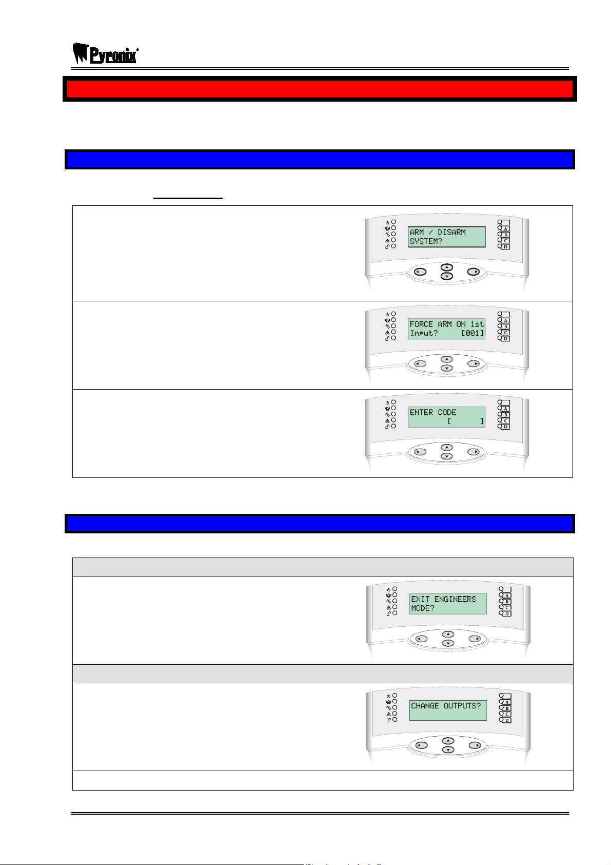
3.1 Entering The Engineers Menu
NOTE: You will not be able to access Engineers Mode if partitions or arm levels are armed. The
system must be fully disarmed
¾ Enter the Engineer Code (default 9999).
¾ Any active faults will be shown. Press
thePkey.
¾ “ARM / DISARM SYSTEM?” will be displayed
in order to gain access to the Engineer Menu.
¾ Press thePkey
¾ “FORCE ARM ON 1st INPUT[01]” will be
displayed
¾ Press thePkey
¾ “ENTER CODE” will be displayed
¾ Enter the Engineers code (default 9999)
¾ “INHIBIT FIRE/HU?” will be displayed indicating
that Engineers Mode has been entered.
Once you are in the Engineer Menu, a high pitch tone will be generated regularly to remind you that you are
still in the Engineer Menu.
3.2 Exiting The Engineer Menu
On completion of programming, the system can be returned back to normal mode by:
METHOD ONE
¾ Use the scroll keys: ^and ! to scroll to
“EXIT ENGINEERS MODE”
¾ Press the Okey
¾ You will be returned to day mode
METHOD TWO
¾ When the display shows any main menu item (i.e.
an item shown in capitals) press the k key, you
will be returned to day mode.
Please see page: 143, for all fault codes that may appear when exiting the Engineers menu.
RINS871-3 Page: 13
Page 14
PCX SMS AND PCX 256 SYSTEM MANUAL
CHAPTER 4: SYSTEM OVERVIEW
This manual supports the following panels: PCX 26/SMS and the PCX 256.
4.1 PCX 26/SMS Input Information
The PCX 26/SMS consists of the following components:
¾ PCX 8 Input Expander
¾ PCX LCD Keypad
Location Inputs Location Inputs
Control Panel
RIX 00
1 – 8
9 – 16
4.2 PCX 256 Input Information
The PCX 256 consists of the following components:
¾ MSX Card
¾ PCX 8 Input Expander
RIX 01
Keypad/Reader 00
17 – 24
25 – 26
¾ PCX LCD Keypad
Location Inputs Location Inputs
Control Panel
RIX 00
RIX 01
RIX 02
RIX 03
RIX 04
RIX 05
RIX 06
RIX 07
RIX 08
RIX 09
RIX 10
RIX 11
RIX 12
RIX 13
RIX 14
RIX 15
RIX 16
RIX 17
1 – 8
9 – 16
17 – 24
25 – 32
33 – 40
41 – 48
49 – 56
57 – 64
65 – 72
73 – 80
81 – 88
89 – 96
97 – 104
105 – 112
113 – 120
121 – 128
129 – 136
137 – 144
145 – 152
RIX 18
RIX 19
RIX 20
RIX 21
RIX 22
RIX 23
RIX 24
RIX 25
RIX 26
RIX 27
RIX 28
Keypad/Reader 00
Keypad/Reader 01
Keypad/Reader 02
Keypad/Reader 03
Keypad/Reader 04
Keypad/Reader 05
Keypad/Reader 06
Keypad/Reader 07
153 – 160
161 – 168
169 – 176
177 – 184
185 – 192
193 – 200
201 – 208
209 – 216
217 – 224
225 – 232
233 – 240
241 – 242
243 – 244
245 – 246
247 – 248
249 – 250
250 – 252
253 – 254
255 – 256
Page: 14 RINS871-3
Page 15
PCX SMS AND PCX 256 SYSTEM MANUAL
4.3 System Overview
4.3.1 Inputs
Inputs on Main Board
Input Expander PCX-RIX
Maximum Inputs Capacity
PCX 26/SMS /
PCX 256
PCX 26/SMS /
PCX 256
8 fully programmable inputs
8 fully programmable inputs
PCX 26/SMS 26 inputs using 2 x PCX RIXs & 1 PCX Keypad
PCX 256 256 inputs using 29 x PCX RIXs & 8 PCX Keypads
Input Configurations
Panel Additions/Expansion
PCX 26/SMS /
PCX 256
DEOL, SEOL
PCX 26/SMS Digi Modem Card
PCX 256 Digi Modem Card, Expansion Card
Unused, Fire, Gas, HU, Silent HU, Tamper, Immediate,
Input Types PCX 26/SMS
Entry/Exit, Access, A (Part EE), EE (Part A), PTS,
Switcher, 24 Hour, Fault, Closure Supervision, Keyswitch
Latched, Entry Shock Input, Keyswitch Pulsed
Unused, Fire, Gas, HU, Silent HU, Tamper, Immediate,
Entry/Exit, Access, A (Part EE), EE (Part A), PTS,
PCX 256
Switcher, 24 Hour, Sub Part Control, Fault, Closure
Supervision, Shunt Input, Disarm Input, Keyswitch
Latched, Entry Shock Input, Keyswitch Pulsed
PCX 26/SMS
Input Attributes
PCX 256
Chime, Omittable, Double Knock, Dual Trip, Normally
Open, Confirm Group.
Chime, Omittable, Double Knock, Dual Trip, Normally
Open, Monitor Activity, Special Logged, Paired Input,
Confirm Group.
4.3.2 Programmable Outputs (PGM)
PGM Outputs On-Board PCX 26/SMS / 256
Output Expander PCX 26/SMS / 256
PCX 26/SMS
Maximum PGM Outputs
PCX 256
Not Used, Fire, Hold Up Any, Intruder Any, Misoperation Any (Abort), Confirmed
Any, Tamper Any, Duress, HU Device Any, Gas, Arm Fail, Entry Deviation,
Secure Intruder Any, Bell Any, Strobe Any, Omit Rearm Any, Unconfirmed Any,
PGM
Types
PCX
26/SMS
Exit Starts Any, Final Arm Any, Strobe Set Fail, Keyswitch Unset, Entry/Exit,
Lights, Reset 1 (Viper Reset), Reset 2 (Viper Arm/Disarm), PIR Latch 1, PIR
Latch 2, Mains Good, Follow Test, Off During Test, Telephone Line Fault, AC
Fail, Battery Faults, Low Volts, Global Fault 1, Global Fault 2, Guard Code
Used, Engineer Access, Initialise Digi, Test ATS.
PGM1, PGM2: Relay (NC,C, NO), Speaker Output,
PGM4, PGM5: Transistor (Active High, Low)
PCX Remote Output Expander 16 Way Relay Outputs.
(PCXROX16R or PCXROX16R/PSU)
20 (4 on board + 1 ROX)
Note: PGMs also on RKPs, RIXs and Readers.
132 (4 on board + 8 ROXs)
Note: PGMs also on RKPs, RIXs and Readers.
RINS871-3 Page: 15
Page 16
PCX SMS AND PCX 256 SYSTEM MANUAL
Fire, Hold Up Any, Intruder Any, Final Arm Any, Misoperation Any (Abort),
Confirmed Any, Tamper Any, Duress, HU Device Any, Gas, Arm Fail, Entry
Deviation, Secure Intruder Any, Bell Any, Strobe Any, Omit Rearm Any,
Unconfirmed Any, Can All Arm, Exit Starts All, Exit Starts Any, Final Arm Any,
PCX 256
Strobe Set Fail, Keyswitch Disarm, Entry, Exit, Entry/Exit, Lights, Follow Input,
Shunt Fault, Reset 1 (Viper Reset), Reset 2 (Viper Arm/Disarm), PIR Latch 1,
PIR Latch 2, Mains Good, Detr Indn Enable, Follow Test, Off During Test,
Telephone Line Fault, AC Fail, Battery Faults, Low Volts, Global Fault 1, Global
Fault 2, German Relay, Guard Code Used, Engineer Access, Initialise Digi, Test
ATE/GSM, Test ATS, Timer, Calendar, Follow Input.
4.3.3 Keypads (PCX-LCD/UK)
Type LCD with integral tag reader. 32 character
Maximum Number of PCX 26/SMS 4 keypads
Keypads PCX 256 16 Keypads
4.3.4 Tag Readers (PCX-PROX/INT & PCX-PROX/EXT)
Types
Internal Tag Reader with 2 inputs & 2 outputs
External Prox Reader with 1 input
Maximum Number of PCX 26/SMS 3 Tag Readers
Readers PCX 256 15 Internal Readers / 7 External Readers
4.3.5 Arm Points
Maximum Number of PCX 26/SMS 4 Arm Points
Arm Points PCX 256 30 Arm Points
4.3.6 Partitions
Number of Partitions/ Arm
Modes
Arming Options Timed Exit, Final Exit, Timed/Final, Push to set,
Timers
PCX 26/SMS 4 Arm Modes
PCX 256 14 Partitions or 14 Arm Modes
Entry Time, Exit Time, Bell Time, Confirm Time, Bell
PCX 26/SMS
Delay, Strobe Time, Re-Arm No, AC Signal Delay,
Speaker, Final Exit delay, Double Knock, Pre-Alarm, Line
Fault, Arm Fail, Guard Code Alarm, Fire Bell Time.
Entry Time, Exit Time, Bell Time, Confirm Time, Bell
Delay, Strobe Time, Re-Arm No, AC Signal Delay,
PCX 256
Speaker, Final Exit delay, Double Knock, Pre-Alarm, Line
Fault, Arm Fail, Guard Code Alarm, Fire Bell Time, Input
NAT days, Input NAT Hours.
4.3.7 User Codes
Number of User Codes
User Code Attributes User Type, Partitions, Arm Options, Flexi Arm
PCX 26/SMS 20 User Codes, 10 Duress Codes.
PCX 256 500 User Codes, 20 Duress Codes.
4.3.8 Central Monitoring Options
Telephone Numbers
Page: 16 RINS871-3
PCX 26/SMS 4 numbers
PCX 256 4 primary numbers and 4 auxillary
Page 17
PCX SMS AND PCX 256 SYSTEM MANUAL
Communication Protocols Fast Format, SIA Level 1, SIA DK, Contact ID, SMS
Group Reporting to CMS
Redials, Time Out, Stop on Success, Test Calls, Low
Battery Report.
Arm, Disarm, Special Disarm, Arm Fail, Alarm, First alarm,
Alarm Silenced, Confirmed, LoTechFault, HiTechFault,
Tech Info, Manager Info, Engineer Info, AccessC Alarm,
Content Types for Contact ID & SMS
AccessC Info, Accessc Ref, SL SwitchON, SL SwitchOFF,
SL OtherOn, SLOtherOff, Sub-partitions Set, Sub-partitions
Unset, Sub-partitions Alarm, Input omitted, Input restore,
Test Call, Mains fail, Emergency input, Emergency restore,
Tamper input, First tamper input, Tamp Input Restore
Telephone Line Monitoring Yes
Digital Communicator Analogue Line and Digi Modem Card.
4.3.9 Other
UDL Programming software. Equipment needed:
Software Support
Memory Event Log
PCX 26/SMS 300
PCX 256 3000
Direct Dial: PCX RS232 lead
Remotely: Modem
RINS871-3 Page: 17
Page 18
PCX SMS AND PCX 256 SYSTEM MANUAL
4.4 DEFAULTS
Functions/Parameters Default Setting
CODES
Engineer Code 9999 9999
User Code 1234 1234
Manager Code 5678 5678
CHOOSE MODE
EOL Range - 4k7 Range
EOL Mode DEOL DEOL
Input Response 400 400
Input XDF Normal Normal
INSTALL RIX
RIX Installed All addresses disabled All addresses disabled
CHANGE INPUTS
All Input Types Unused Unused
Input Partitions A A
Input Partition Any Any
Chime No No
Omittable No No
Double Knock No No
Dual Trip No No
Normally Open No No
Monitor Activity - No
Special Log - No
Paired Input - No
Confirm Group 00 00
Input Name Input ### (Text String) Input ### (Text String)
ASSIGN KEYPADS/READERS
Address 00 Keypad Keypad
All other addresses Not Used Not Used
Arm Point Arms - 0123456789ABCD
Arm Point Disarms - 0123456789ABCD
Arm Point In - A
Default Level A Arm Point Name Device ## (Text String) Device ## (Text String)
SYSTEM DISPLAYS
Partition Text Partition # (Text String) Partition # (Text String)
Full Partition Text - Full (Text String)
Sign On Message PCX 26.V5.e (Text String) PCX 256.V5.e (Text String)
Site Name _ (Text String) _ (Text String)
Display When Arm - No
CHANGE TIMERS
Entry Time 30 seconds (All partitions) 30 seconds (All partitions)
Exit Time 30 seconds (All partitions) 30 seconds (All partitions)
Bell Time 15 minutes 15 minutes
Confirm Time 30 minutes 30 minutes
Bell Delay Zero minutes Zero minutes
Strobe Time Zero minutes Zero minutes
Re-Arm No. 3 3
AC Signal Delay 40 minutes 60 minutes
Speaker Zero seconds Zero seconds
Final Exit Delay 5 seconds 5 seconds
Double Knock 10 seconds 10 seconds
PCX 26/SMS PCX 256
PCX 26/SMS PCX 256
PCX 26/SMS PCX 256
PCX 26/SMS PCX 256
PCX 26/SMS PCX 256
PCX 26/SMS PCX 256
PCX 26/SMS PCX 256
Page: 18 RINS871-3
Page 19
PCX SMS AND PCX 256 SYSTEM MANUAL
Functions/Parameters Default Setting
Pre-Alarm 30 seconds 30 seconds
Line Fault 20 seconds 20 seconds
Arm Fail 40 seconds 40 seconds
Guard Code Alarm 3 minutes 3 minutes
Fire Bell Time 99 minutes 99 minutes
Input NAT days - 14
Input NAT hours - Zero
EXIT MODES
PCX 26/SMS PCX 256
All Partition Exit Modes Timed Timed
CHANGE CODES
PCX 26/SMS PCX 256
5 Digit Pins - Yes
Change Duress Codes None None
Change Master Manager Code 5678 5678
Change Engineer Code 9999 9999
VOLUME CONTROL
PCX 26/SMS PCX 256
Partition Entry 4 4
Partition Exit 4 4
Alarm 7 7
Fire 7 7
Tamper 6 6
Disarmed 6 6
Chime 3 3
Intelligent Arm 3 3
Code Stops Sound Yes Yes
E/E Keypads Only No No
Alert Kps Only Yes Yes
ALARM RESPONSE
PCX 26/SMS PCX 256
Silent 1st Alarm Never Never
Disable Confirm On Entry No No
Inputs to Confirm After Entry 2 2
Partitions Starts Digi Digi
Partitions Stops Confirm Confirm
Fire/Gas/HU Starts at Digi Digi
Fire/Gas/HU Stops at Digi Digi
Disarm Starts Bells Only Bells Only
Disarm Stops Bells Only Bells Only
Start At - Digi
If Partition set - None
Start At - Digi
If Partition set - None
CHANGE OUTPUTS
PCX 26/SMS PCX 256
Endstation Outputs PGM 1 PIR Latch 1 PIR Latch 1
Endstation Outputs PGM 2 Not Used Not Used
Endstation Outputs PGM 4 Strobe Any Strobe Any
Endstation Outputs PGM 5 Bells Any Bells Any
ATE Pin 1 Fire Fire
ATE Pin 2 HU Device Any HU Device Any
ATE Pin 3 Unconfirmed Any Unconfirmed Any
ATE Pin 4 Final Arm Any Final Arm Any
ATE Pin 5 Tamper Any Omit Re-arm Any
ATE Pin 6 Confirmed Any Tamper Any
ATE Pin 7 Omit Rearm Any Confirmed Any
ATE Pin 8 Global Fault 2 AC Fail
RINS871-3 Page: 19
Page 20
PCX SMS AND PCX 256 SYSTEM MANUAL
Functions/Parameters Default Setting
ATE Pin 9 Global Fault 1 Global Fault 2
ATE Pin 10 Test ATS Test ATS
RIX PGMs All Not Used All Not Used
ROX Module PGMs All Not Used All Not Used
Keypad PGMs All Not Used All Not Used
Reader PGMs All Not Used All Not Used
INTELLIGENT ARM
PCX 26/SMS PCX 256
Intelligent No No
SITE OPTIONS
PCX 26/SMS PCX 256
Arm With Fault No Yes
Arm With Tamper+ No No
Arm With ATS Flt Yes Yes
Arm Part TFault - Yes
Arm Fail = Alarm No No
Do Battery Load Test No No
Part Misoperate No No
Strobe Confirm No No
Re-Arm Omits No No
Use Level Arm - No
Confirmed When Final Arm Final Arm
Autoset Force - No
Restrict PIN Use No Yes
Invert ATE O/Ps Yes Yes
Common Exit Mode - Yes
Flexi Unset No No
2 Key HU None None
ATE Inputs None None
ENGINEER RESTORE OPTIONS?
PCX 26/SMS PCX 256
Engineer Restore Intruder No No
Engineer Restore HU No No
Engineer Restore Tamper No Yes
Engineer Restore Soak No No
Engineer Restore Confirmed No Yes
Engineer Restore Faults No Yes
Anti-code Restore No Yes
ENGINEER TESTS?
PCX 26/SMS PCX 256
Sound To play - No Sound
SET UP DOWNLOADING?
PCX 26/SMS PCX 256
Download by None None
(modem) Security Mode Auto-Answer Auto-Answer
Telephone Line Dedicated Dedicated
Number of Rings to Prime - 03
Modem Speed High High
Arm Tel No Blank Blank
Modem Tel No Blank Blank
Signal Alarms - No
Signal Faults - No
Signal Open/Close - No
Signal Access C - No
PROGRAMME DIGI/SMS?
PCX 26/SMS PCX 256
Disable Digi/SMS Yes Yes
Active No No
Choose Format Fast 4.8.1 Fast 4.8.1
Page: 20 RINS871-3
Page 21
PCX SMS AND PCX 256 SYSTEM MANUAL
Functions/Parameters Default Setting
Stop On Sucess Yes Yes
Redials 3 3
Time Out 15 15
Low Batt Report No No
Test Calls No No
Digi Channel 1 Fire Fire
Digi Channel 2 HU Device Any HU Device Any
Digi Channel 3 Unconfirmed Any Unconfirmed Any
Digi Channel 4 Final Arm Any Final Arm Any
Digi Channel 5 Tamper Any Omit Rearm Any
Digi Channel 6 Confirmed Any Unused
Digi Channel 7 Omit rearm any Confirmed Any
Digi Channel 8 AC Fail AC Fail
Digi Channel 9 Global Fault 1 Global Fault 2
Digi Channel 10 Test ATS Test ATS
Digi Channels 11-16 Not Used Not Used
3 Way Calling No No
DIAL OUT MENU
PCX 26/SMS PCX 256
Select Operation Are You Sure? Connect to PC
RINS871-3 Page: 21
Page 22
PCX SMS AND PCX 256 SYSTEM MANUAL
CHAPTER 5: TECHNICAL SPECIFICATION
This chapter outlines the essential specifications for the PCX range.
Pyronix Ltd. reserves the right to change these specifications at any time, without notice, in the interests of
product improvement.
Please ensure that this information is used in designing the system, so that it can be installed and
programmed as intended, and will continue to function reliably. In particular, system outputs and power
supplies must be used within their rated specifications.
5.1 Introduction
The PCX range has been designed to offer a choice of options to suit most European security applications.
All systems can be controlled using PIN code and/or proximity cards.
All products are compatible with the Digi Modem for remote signalling, downloading and/or SMS text
messaging.
Training courses are available on application to the sales office.
EN-50131
The PCX range is suitable for installation in systems specified below:
Product Security Grade Environmental Class
PCX 26/SMS 1 and 2 1 and 2
PCX 256 1 to 3 1 and 2
Power supplies conform to EN-501346
BS-4737
The PCX range has the facilities required to be able to control a system installed to BS-4737 requirements.
Compliance Statement
The PCX range complies with the requirements of the European EMC Directive (89/336/EC) and
the Low Voltage Directive (72/23/EC and 93/68/EC).
It is essential that the recommendations in this manual are followed, and that equipment and wiring be
installed so as to avoid the effects of potential sources of interference.
The PCX range fully complies with the requirements of DD243:2002. This has been verified using the BSIA
“Manufacturer’s Check List for Compliance with the Requirements of DD243:2002”.
All appropriate facilities and options are available for systems using sequential confirmation signalling
except: Zeroing of ‘Confirm Timer’ if first input to alarm retriggers.
When all parts are working normally, this equipment in combination with the PSTN and suitable
ARC equipment will meet the requirements of ATS2.
PCX 26/SMS/26: This product complies with TS50131-3:2003 and is suitable for use in EN50131-
6:1998 systems at security grade 2, environmental class 2.
UK = Suitable for use with systems installed to PD6662:2004 (AMD)
EXPORT = Suitable for use with systems installed to EN50131-1
PCX 256: This product complies with TS50131-3:2003 and is suitable for use in EN50131-6:1998
systems at security grade 3, environmental class 2.
UK = Suitable for use with systems installed to PD6662:2004 (AMD)
EXPORT = Suitable for use with systems installed to EN50131-1
Page: 22 RINS871-3
Page 23
PCX SMS AND PCX 256 SYSTEM MANUAL
5.2 Warranty
This product is sold subject to our standard warranty conditions and is warranted against defects in
workmanship for a period of 2 years. In the interest of continuing improvement of quality, customer care and
design, Pyronix reserves the right to amend specifications without giving prior notice.
5.3 PCX System Specifications
SYSTEM ANALYSIS PCX 26/SMS PCX 256
Power Supply 1.5A 1.5A
Inputs (max) 26 256
Arm Points (max) 4 30
Full Partitions - 14
Part-Sets 4 14
Sub-Parts (max) - 16
User / Manager Codes* 20 500
Duress/Guard Codes* 10 20
Logs 750 3000
Access Control (max) - 15
RIX Modules 2 25
ROX Modules 1 8
FUSES VALUES
F1 (PGMs) 800mA fast blow RFSE016 = F800mAL glass body
F2 (BELL) 800mA fast blow RFSE016 = F800mAL glass body
F3 (AUX) 800mA fast blow RFSE016 = F800mAL glass body
F4 (BUS) 800mA fast blow RFSE016 = F800mAL glass body
F5 (BATTERY) 3.15A slow blow RFSE027 = T3.15AL Glass body
POWER SUPPLY
Power Input 17V AC
Transformer Rating 27VA
Input Voltage 230V AC
Output Voltage 12V DC nominal
EN50131-6 Type A
Voltage Range 13.60 – 14.9V DC
Ripple 5mV @ 1.5A
Panel Current Req. End Station: 75-90mA
Total Current Output 1.5A
BATTERY
Battery Type 12V Lead Acid
Recharge Time PCX 26/SMS: 72 hours
Recharge Time PCX 256: 24 hours
Battery Capacity 22Ahr Max
INPUTS (ACTIVATION RESISTANCE)
Normal 3K7 to 8K3
Intruder 8K4 to 10K2
Fault 10K3 to 14K9
Masking 15K to 23K
Tamper <3K7 or >23K
Standard to which component claims compliance
CIE: DD/CLC TS50131-1:2003, as reconciled with PD6662:2004 by BSIA Form 179
PSU: EN50131-6:1998, as clarified by BSIA Form 180
PROGRAMMABLE OUTPUTS (PGMS)
PGM 1 (relay) 30V @ 3A
PGM 2 (relay) 30V @ 3A
Speaker 16 ohms
PGM 4 (transistor) 500mA
PGM 5 (transistor) 500mA
TEMPERATURES
Operational -10°C to +40°C. (14°F to 104°F)
Storage -20°C to +60°C. (-4°F to 140°F)
DIMENSIONS
Casing 390 x 305 x 100mm
Printed Circuit Board 150 x 175 x 30mm
VARIATIONS LOGICAL / PHYSICAL KEYS
4-digit codes 10,000
5-digit codes 100,000
Disallowed codes None
Other logical keys 16
12
Method
According to TS50131-3:2003 Annex B
According to spec of manufacturer of RFiD
components used
RINS871-3 Page: 23
Page 24

PCX SMS AND PCX 256 SYSTEM MANUAL
5.4 Devices Technical Specification
LCD KEYPAD (PCX-LCD/UK)
Supply Voltage 13.8V (9-16V range)
Supply Current
Min brightness setting 80mA
Max brightness setting 150mA
Operating Temperature 0 to 50°C
Dimension 139 x 127 x 29mm
Output (PGM) Current 100mA
EXTERNAL TAG READER (PCX-PROX/EXT)
Supply Voltage 13.8V (9-16V range)
Supply Current Max. 90mA @ 13.8V
Operating Temperature -10 to +50°C
Dimensions 85 x 85 x 21mm
INTERNAL TAG READER (PCX-PROX/INT)
Supply Voltage 10.5 to 15V
Supply Current 60mA
Operating Temperature -10°C to +40°C
Dimension 100 x 70 x 30mm
Output (PGM) Current 100mA
Supply Voltage 10.5 to 15V
REMOTE INPUT EXPANDER (PCX-RIX2)
Supply Voltage 10.5 to 15V
Supply Current 40mA
Operating Temperature -10°C to +40°C
Dimension 100 x 70 x 30mm
Output (PGM) Current 500mA
REMOTE INPUT EXPANDER (PCX-RIX8)
Supply Voltage 10.5V to 15V
Quiescent Current 30mA
Dimensions 210 x 130 x 50 mm
REMOTE INPUT EXPANDER (PCX-RIX8+)
Supply Voltage 10.5 to 15V
Supply Current 40mA
Operating Temperature -10°C to +40°C
Dimension 100 x 70 x 30mm
Output (PGM) Current 500mA
Supply Voltage 10.5 to 15V
REMOTE OUTPUT EXPANDER (PCX-ROX16R)
Supply Voltage 10.5V to 15V
Supply Current 30mA (no relays active)
Supply Current 340mA (all relays active)
Max Switching Voltage 24A
Max Switching Current 3A
POWER SUPPLIES FOR RIXs and ROXs
Power Supply 2.5A
Mains (220-240V AC) 50Hz 150mA
Mains Fuse Slow Blow (T) 250mA
Output 13.75V 1.0A continuous
Battery Fuse 3.15A Quick Blow
Output Fuse 1.25A Quick Blow
5.4.1 Lightning Protection
The inbuilt lightning protection is provided by fast acting gas discharge tubes.
The quality of the protection is protected upon the low impedance telecoms earth being connected.
5.4.2 Code Guessing
When the PCX is armed, an intruder may try to ‘guess’ the user code to disarm the system, the PCX
incorporates a feature that stops this; If 30 or more invalid key presses are input, or 6 invalid tags are
presented at the keypad, the keypad will disable or ‘freeze’ for 90 seconds. It will then subsequently ‘freeze’
after 7 further invalid key presses or another invalid tag is presented.
After the lock up time has timed out, a valid user code/tag may be presented and the system will disarm.
‘Code Guessing’ will be visible on the keypad. To clear this press P.
Page: 24 RINS871-3
Page 25
PCX SMS AND PCX 256 SYSTEM MANUAL
CHAPTER 6: SAFETY
SAFETY
1. A technically competent person must carry out the mains installation in accordance with the national and
local electrical installation regulations
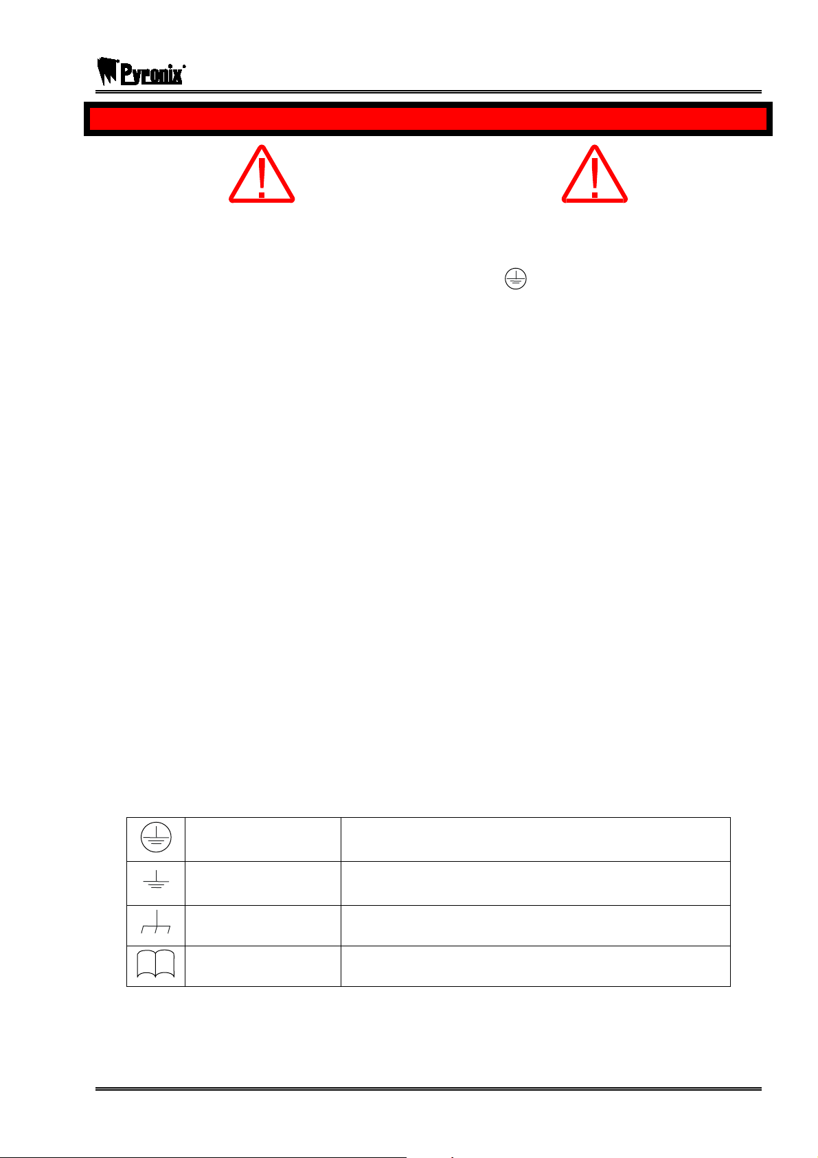
2. Protective Earth: This equipment must be earthed/grounded.
3. Functional Earth: Must be connected to earth terminal to allow the equipment to operate correctly. Has
no safety implications.
2
4. Connect the unit to a single pole, unswitched, 3 Amp fused spur, using 0.75mm
cannot be positively identified use a double pole disconnect version.
5. Always remove / isolate the mains supply before carrying out any servicing of the panel.
6. Fuses: For continued protection against the risk of fire, replace only with the same type and rating of
fuse.
7. There are no user serviceable parts inside the equipment.
cable. If the Neutral
8. This unit should be mounted so that there will be no outside access to the electrical cable entry point.
9. Ventilation: To ensure the correct airflow, always mount the unit vertically with the unit having a clear
space on all sides. It must not be covered by clothes, furnishings, boxes, etc. It must not be mounted
close to, or above, heat radiating sources.
10. On completion of wiring, use tie-wraps to prevent any loose wires causing a safety hazard.
11. The mechanical mounting of the unit must be secure enough to carry the full weight of the unit including
all batteries.
12. Batteries: Ensure that the battery terminal connections will not create an electrical short-circuit on the
case metalwork when the unit is closed. Use insulated battery lead connectors.
13. Dispose of old batteries as required by environmental legislation / recommendations.
14. The battery case must have a flame-retardant rating of UL94-V2/V1/V0 – IEC60950:2000
15. Water: The equipment must be kept free from dampness, water and any other liquids. It is only suitable
for installation indoors.
Protective Earth
Protective Bonding
Must be connected to the electrical installation earth / ground
Must be connected to the equipment protective earth terminal
Functional Earth
Read
RINS871-3 Page: 25
Must be connected to earth terminal to allow the equipment to
operate correctly. Has no safety implications.
Read equipment instructions
Page 26

PCX SMS AND PCX 256 SYSTEM MANUAL
CHAPTER 7: INSTALLATION
This chapter describes the recommended procedure for installing PCX systems
7.1 Electromagnetic Compatibility (EMC)
The PCX system has been designed to meet or exceed all relevant EMC requirements. This alone does not
guarantee that no problems will be experienced, especially in relation to older equipment not designed to the
same standards, or to equipment for which the same provisions of the EMC Directive do not apply.
To maintain full EMC performance for the system, it is essential that the following points be followed:
a. All other equipment used must carry the CE mark for electromagnetic compatibility.
b. Do not locate the PCX system, or any other component, close to equipment switching high frequencies,
or using radio frequencies in its operation.
c. Avoid using mains supplies contaminated by interference generated by switching, arcing, etc.
d. The system must be connected to a good, clean earth. The earth connection of housing lids is a
mandatory safety requirement.
e. The correct cable type should be used for each application as specified.
f. Cables should be routed to avoid the possibility of interference being picked up from other nearby cabling
or equipment. Be alert to the possibility of other cables being installed after the alarm system has been
commissioned.
For further information refer to BSIA “EMC Guidelines for Alarm Installers”.
7.2 Mounting Procedure for the PCX system
The following steps illustrate basic mounting procedure for the PCX metal case.
Step 1 – Remove the case lid from the PCX panel and check all parts and components are in place.
Step 2 – Decide where the PCX panel will be situated. The PCX panel may be housed in the loft or different
rooms in the premises. A discrete and concealed place is advisable, as only the PCX keypads need to be
seen.
Step 3 – Secure the PCX panel to a sturdy and stable surface, using the mounting screws provided. First
mark the wall where the panel is to be situated (using the mounting holes), drill holes in the wall, and fasten
the panel base to the wall using the screws provided.
Step 4 – Before the panel base is completely secured to the wall feed cables for keypads / AC power supply
/ and accessories through the cable entry holes as illustrated.
7.3 Resistors
The resistor values are recognised as follows:
4k7 resistor = Yellow/Violet/Red
6k8 resistor = Blue/Grey/Red
470Ω resistor = Yellow/Violet/Brown
The PCX System recognises the following:
4k7: Alarm
4k7: Tamper
6k8: Mask/Fault (Not applicable on PCX 26/SMS)
Page: 26 RINS871-3
Page 27
PCX SMS AND PCX 256 SYSTEM MANUAL
h
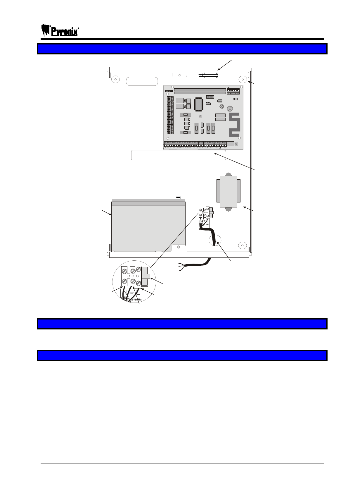
7.4 The PCX Panel Layout
Tam per Sw itc
Battery
17Ah
17Ah
DIGI MODEM CARD SLOT
EXPANSION CARD SLOT
T
A
M
P
E
R
NO1
C1
NC1
NO2
C2
NC2
F1
AUX+
PGM3
PGM4
PGM5
BT
B-
B+
F3 F4 F5
F2
T-1 R-1 TIP RING
Wall Fixing
Holes
Cable
Entry Holes
Mains
Tran sforme r
Neutral
Earth
To M ai ns Su pp ly
Fuse carrier handle
(fuse nominal - 250m A)
Live
Main Cable
Entry Hole
7.5 Battery Installation Procedure
Place two foam pads on the bottom of the battery and two on the upper rear. Place the battery in the case
and secure with two tie wraps.
7.6 Mounting Procedure for Devices
Mount the equipment carefully in suitable locations, noting particularly the following:
a. Input expander units (RIXs or RIX2s) should be located to suit the wiring to appropriate detectors.
Mounting more than two together is not recommended.
b. Where input expanders, output modules or access controllers are mounted on power supplies, all
connections are automatically made to draw all current from the power supply, and to use the system
diagnostic capabilities to control the power supply.
c. Intelligent power supplies cannot be used in isolation from the PCX system plug-on PCBs.
d. Keypads and tag readers should NOT be mounted on or near a metal surface, or within a metre of each
other, or tag response could be affected.
e. Where provided, metal housings must have the earth strap connected to the lid to meet electrical safety
regulations.
RINS871-3 Page: 27
Page 28

PCX SMS AND PCX 256 SYSTEM MANUAL
A
7.7 Tamper Switch
The Tamper switch that is already fitted onto the metal case connects via a plug-on connector to the tamper
pins on the PCX control panel as shown below:
Tam p er S w it c h
COMMUNICATION C ARD
COMMS PGMS
NC1
C1
NO1
NC2
C2
NO2
AUX+
SPK
---------- ------SA B---- --------- ---
TR
B-
B+
TAMPER
EXPANSIO N CAR D SLO T
PGMS
F1
BELL
F2
RESET
BUS
AUX
F3 F4 F5
ENGINEER
KEYPAD
RS232
BATTERY
-1 B-1 A B
BATTERY
CONNEC T
7.8 Mains Connection
MAINS ELECTRICITY IS DANGEROUS!
Mains connection must be performed by a qualified electrician, in accordance with electrical wiring
regulations (BS.7671).
The earth connection must be correctly made to the centre terminal of the mains block, and to terminal G1 of
the End Station, and of any intelligent power supplies.
Metal lids must be correctly connected to mains earth by the wiring loom provided, before securing in
position.
Note:
The PCB ground connection is NOT a safety earth connection, but is for EMC filtering
purposes.
Warning:
Always disconnect the mains supply before removing the cover and working on the
equipment.
7.9 System Connections
Note: Never add equipment to the system with power applied, or damage can result.
Please refer to the following diagrams to identify the functions of all the terminals on PCX components. Note
that all components use the same identification for equivalent applications – e.g. D1, D2, D3 and D4 will
always be the RS-485 terminations, etc.
7.10 Digi Modem Card
Information for installing the Digi Modem Card is shown separately on page 110.
7.11 Expander Card
Information for installing the Expander card is shown separately on page 112. Please note that this is not
available on the PCX 26/SMS.
7.12 Access Control and Guard Tour Equipment
Information for installing access control and guard tour equipment is shown in page: 138. Please note that
this is not available on the PCX 26/SMS.
Page: 28 RINS871-3
Page 29
PCX SMS AND PCX 256 SYSTEM MANUAL
7.13 Cabling Information
7.13.1 Planning the Cable Routes
Care should be taken to avoid running alarm cables in the same trunking as, or otherwise close to, cables
carrying signals that may cause interference – e.g. telephone cables, etc.
Similarly, where practical, avoid routing cables close to equipment capable of generating interference – e.g.
fluorescent lighting, welding equipment, etc.
Never run alarm cables in the same trunking as mains cables.
7.13.2 Screened Cable
When screened cable is used, the screen should be terminated at the control panel (or RIX module) only.
For best results, connect to the metalwork immediately at the point of cable entry into the housing, with a
‘pigtail’ not exceeding 5cm.
Terminals are provided in all PCX housings for this purpose.
Cables should not be looped inside the housings, or routed across or underneath printed circuit boards.
Ensure that screen connections are continuous through all intermediate detectors, junction boxes, etc.
7.13.3 Wiring Specifications
NOTE: The following specifications must be observed when installing PCX alarm systems.
General Principals
1 Routing: No alarm system cable should be run with other cables carrying AC or digital signals.
2 Insulation: Should be protected by the use of grommets, etc. where appropriate.
3 Specifications: The following specifications for cable types and distances are important for reliable
operation.
RS-485 Wiring
1 Cores:
2 Cable Type:
3 Wiring Format: Parallel, ‘daisy-chained’.
4 Cable Length: Overall network max. 1Km.
5 Termination: Extreme end points fitted with 470Ω resistors between A (D3) and B (D4).
4-core minimum. Use of 6-core and doubling up of power supply core is
beneficial to minimise voltage drops, but never double communications
connections.
As much as it is good practice to use screened cable, the PCX RS485 bus will
operate with standard alarm cable up to 300m. After 300m a 485 repeater device
will be required to be fitted when wiring keypads, prox readers, RIXs and ROXs.
The PCX system requires standard 7/0.2 unscreened alarm cable when wiring
keypads, prox readers, RIXs and ROXs.
Screened cable should be used if the system has been installed in hostile
environments where there maybe high levels of Radio Frequencies or mains
interference, e.g. heavy plant welding.
Example: Twisted pair, e.g. Belden 9744 (unscreened) or 9502 (screened).
End of Line Input Wiring
1 Cores: 4-core.
2 Cable Type: Standard alarm cable, screened in poor environments.
3 Wiring Format: Detectors individually wired, using EOL resistors mounted at detector.
4 Cable Length: Max. 1Km per detector.
RINS871-3 Page: 29
Page 30
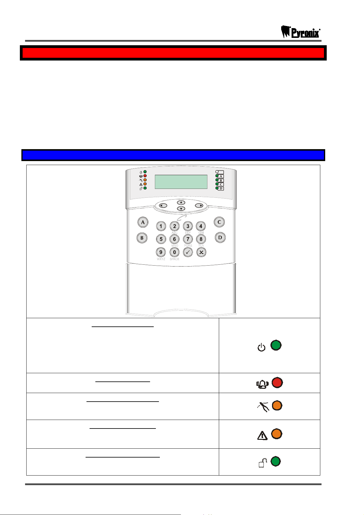
PCX SMS AND PCX 256 SYSTEM MANUAL
g
CHAPTER 8: KEYPAD AND READER INDICATIONS
The PCX panel is active for 24 hours a day and the two basic operation modes are DISARMED mode and
ARMED mode.
DISARMED: In this mode all inputs are disarmed, apart from Fire, Hold Up, 24 Hour, Gas, Tamper and
Fault, which are active 24 hours a day. The Tamper state of all End of Line inputs is always active
irrespective of the input type.
ARMED: In this mode all enabled inputs are armed, and if triggered will generate an alarm condition. If an
alarm is triggered, internal and external sounders will operate for a programmed period or time. Upon expiry
of this time period, the system will automatically rearm.
There are 3 types of operating devices for the PCX: The LCD keypad, the internal proximity reader and the
external proximity reader. Also note that the PCX LCD keypad also has an inbuilt prox reader.
8.1 The PCX LCD Keypad (PCX-LCD/UK)
PCX 256.v5.e
!!
Time 14:48 c
Ta
,/+.
JKL
ALERT LED (GREEN)
The Alert LED will flash if there is information available to you. Enter
your code to see the information. After a code has been entered,
one of the following LEDs will light: Tamper or Fault. The relevant
detail of the problem will be shown on the display. To clear the
display, press the ‘Yes’ key (the display will clear automatically after
3 minutes).
A
B
C
D
ALARM LED (RED)
This indicates that alarm activation has occurred.
TAMPER LED (ORANGE)
This indicates that a tamper has occurred (only visible when a valid
code / tag has been used)
FAULT LED (ORANGE)
This indicates that a fault has occurred, i.e. device fail etc.
(only visible when a valid code / tag has been used)
!!!!!!!!!!!!!!!!!!!!!!!!!!!!!!!!!!!!!!!!!!!!!!!!!!
DISARMED LED (GREEN)
This will illuminate for a couple of seconds after the system has been
disarmed.
Page: 30 RINS871-3
Page 31

PCX SMS AND PCX 256 SYSTEM MANUAL
NUMERICAL BUTTONS
Used to enter user codes, programming the system and text
programming.
DIRECTION BUTTONS
Used to select options and scroll display.
OPERATIONAL BUTTON 1
Selects items and enters sub menu indicated.
Used to arm the panel when flexi-arm is enabled.
OPERATIONAL BUTTON 2
Moves forward to the next main menu item, also clears faults.
THE A KEY
Exit Engineers Mode (from a main menu item)
THE B KEY
Moves backwards to the previous menu item
THE C KEY
Chime Button and displays additional information in the log and the
diagnostic functions.
THE D KEY
Moves forward to the next option, or toggles between ‘YES/NO’
choices. Enters the manager mode.
The emergency buttons for the PCX system consist of 2 buttons being pressed to activate a Hold Up. These
are the keys and. On default these are disabled to comply with PD6662. If you wish for these to be
enabled please see the function ‘2 Key HU’ in ‘Site Options’ on page: 84.
RINS871-3 Page: 31
Page 32

PCX SMS AND PCX 256 SYSTEM MANUAL
8.2 The Internal Reader (PCX-PROX/INT)
Alert
Alarm
Tamper
Fault
Unset
Tag
ALERT LED
The Alert LED will flash if there is information available to you. Enter
your code to see the information. After a code has been entered,
one of the following LEDs will light: Tamper or Fault. The relevant
detail of the problem will be shown on the display. To clear the
display, press the ‘Yes’ key (the display will clear automatically after
3 minutes).
PowerPowerPowerPowerPowerPowerPowerPowerPowerPowerPowerPowerPowerPowerPowerPowerPowerPowerPowerPowerPowerPowerPowerPowerPower
ALARM LED
This indicates when an alarm activation as occurred.
TAMPER LED
This indicates when a tamper has occurred.
FAULT LED
This indicates when a fault has occurred, i.e. device fail etc.
DISARMED LED
This will illuminate for a couple of seconds after the system has been
disarmed.
AlarmAlarmAlarmAlarmAlarmAlarmAlarmAlarmAlarmAlarmAlarmAlarmAlarmAlarmAlarmAlarmAlarmAlarmAlarmAlarmAlarmAlarmAlarmAlarmAlarm
Tamp erTamp erTamp erTamp erTamp erTamp erTamp erTamp erTamp erTamp erTamp erTamp erTamp erTamp erTamp erTamp erTamp erTamp erTamp erTamp erTamp erTamp erTamp erTamp erTamp er
FaultFaultFaultFaultFaultFaultFaultFaultFaultFaultFaultFaultFaultFaultFaultFaultFaultFaultFaultFaultFaultFaultFaultFaultFault
UnsetUnsetUnsetUnsetUnsetUnsetUnsetUnsetUnsetUnsetUnsetUnsetUnsetUnsetUnsetUnsetUnsetUnsetUnsetUnsetUnsetUnsetUnsetUnsetUnset
Page: 32 RINS871-3
Page 33

PCX SMS AND PCX 256 SYSTEM MANUAL
8.3 The External Reader (PCX-PROX/EXT)
GREEN LED
This indicated that the reader is ready to accept a tag. This will
extinguish after a couple of seconds.
RED LED
This can be programmed to follow an output (For example you may
want the output to illuminate when a partition is armed). For more
information on this please see ‘Change Outputs’.
The prox tags that are used with the PCX-PROX/INT and PCX-PROX/EXT are shown below:
These can be ordered as a pack of 5 (PCX-PTAG)
RINS871-3 Page: 33
Page 34

PCX SMS AND PCX 256 SYSTEM MANUAL
CHAPTER 9: THE PCX DEVICES
This section summarises the components available to complete the PCX systems.
PCX-LCD/UK: LCD English Keypad (with integrated tag reader)
Assign the keypads in the function ‘Assign Keypads/Readers’. Please see page: 60
Please note that the first keypad on the system will always be addressed as ‘00’.
The keypads are joined to the same data bus as: PCX-PROX/INT, PCX-PROX/EXT, PCX-RIX2.
PCX-PROX/INT : Internal Tag Reader
Assign the readers in the function ‘Assign Keypads/Readers’. Please see page: 60
Please note that the first reader on the system will start addressing at ‘01’.
The readers are joined to the same data bus as: PCX-LCD/UK, PCX-PROX/EXT, PCX-RIX2.
PCX-PROX/EXT: External Tag Reader
Assign the readers in the function ‘Assign Keypads/Readers’. Please see page: 60
Please note that the first reader on the system will start addressing at ‘01’.
The readers are joined to the same data bus as: PCX-LCD/UK, PCX-PROX/INT, PCX-RIX2
PCX-PROXSHROUD/S: Metal Shroud for the PCX-PROX/EXT
Stainless Steal
PCX-PROXSHROUD/P: Metal Shroud for the PCX-PROX/EXT
Black painted
PCX-PTAG: Proximity Tags
All tags can be used on the PCX-LCD/UK, PCX-PROX/INT and PCX-PROX/EXT.
They can be programmed in the master manager function ‘Change Codes’
These come in packs of 5.
PCX-RIX2: 2 input expander
Assign the RIX2 in the function ‘Assign Keypads/Readers’. (the RIX2 is programmed as a reader)
Please see page: 60.
Please note that the first RIX2 on the system will start addressing at ‘01’.
The readers are joined to the same data bus as: PCX-LCD/UK, PCX-PROX/INT, PCX-RIX2
PCX-RIX8: 8 input expander
Assign the RIX8 in the function ‘Install RIX’. Please see page: 48
RIX’s are on their own data line, therefore the addressing will start at ‘00’. These are recognised by the dip
switches on the RIX.
PCX-RIX8+: 8 input expander with 4 PGMs.
Assign the RIX8 in the function ‘Install RIX’. Please see page: 48
RIX’s are on their own data line, therefore the addressing will start at ‘00’. These are recognised by the dip
switches on the RIX.
PCX-RIX8+/PSU: 8 input expander with 4 PGMs with 1.5A Power Supply
See ‘PCX-RIX8+’.
PCX-ROX16R: 16 way relay output module
Assign the ROX16R in the function ‘Change Outputs’ and select ‘ROX Module PGMs’. Please see page: 80
ROX’s are on their own data line, therefore the addressing will start at ‘00’. These are recognised by the dip
switches on the ROX.
PCX-ROX16R/PSU: 16 way relay output module with 1.5A Power Supply
See ‘PCX-ROX16R’.
Page: 34 RINS871-3
Page 35

PCX SMS AND PCX 256 SYSTEM MANUAL
PCX-ACCESS: Access control module
Assign the PCX-ACCESS as a reader (and then as access control) in the function ‘Assign
Keypads/Readers’.
Please note that the first reader on the system will start addressing at ‘01’.
These are recognised by the dip switches on the Access PCB.
Please note the PCX-ACCESS is not available on the PCX 26/SMS.
PCX-RS232L: RS232 Lead for upload/download
Assign uploading/downloading in the function ‘Set up Downloading’. Please see page: 95
PCX-DIGI+ARM: Digi/Arm Card
Assign the digi in the function ‘Programme Digi/SMS’. Please see page: 97
PCX-CABINET: Metal Housing for the PCX
NOTE: For the part codes of these products add “FP” in front of the “Name”, e.g. FPPCX-RIX2 for a
RIX2 Module. For all radio products please contact our sales department.
When a new device has been installed, it must be addressed and programmed into the PCX system
via Engineers Mode.
RINS871-3 Page: 35
Page 36

PCX SMS AND PCX 256 SYSTEM MANUAL
CHAPTER 10: NOTES ON THE PCX SYSTEM
This chapter outlines the features and functions the PCX system can offer.
10.1 Partition / Level Arm System
The PCX 26/SMS can have up to 4 arm modes, and the PCX 256 can have up to 14 partitions or arm
modes.
In the PCX 256 system, you may choose how you want the system to operate, either by arm modes or
partitions; this option is in Site Options under ‘User Level Arm’ on page 84.
10.1.1 PCX 26/SMS Level Arming
The PCX 26/SMS system can operate 4 different arm modes. This means that the user can choose which
arm mode to set, for example one arm mode (Arm Mode A) might arm all the house, another (Arm Mode B)
may arm just the downstairs of the property for a night time set. This is all programmable in the Engineers
Menu.
10.1.2 PCX 256 Partition / Level Arming
The PCX 256 system can operate with 14 partitions or 14 different arm modes. Partitions can be used to
separate inputs, user codes and peripherals, and more than one partition can be armed or disarmed at any
time. Partitioning a system is useful when the PCX 256 system is operating a block of flats or different offices
for example. Please note that the primary partitions are A, B, C and D.
The PCX 256 system can also be programmed to be used as a level arming system and can have up to 14
different arm modes programmed. Please see Site Options under ‘User Level Arm’ on page 84.
To program common partitions please see page: 51.
10.2 Arming / Disarming The System
Each PCX keypad can be used to arm and disarm the system, whether that be via a user code which is
programmed into the system, or via the inbuilt proximity reader that is present on all PCX keypads. Please
see the user manual in the appendix (page: 156) for more information. You may also use an internal
proximity reader and an external proximity reader to arm/disarm the system.
10.2.1 Flexi Arm
Flexi Arm can be selected for each individual user code, which is used so the user can select which level
arm/partitions to arm/disarm (depending on the partitions they have assigned to). If Flexi-arm is selected as
‘No’ then once card/code is presented, the system will automatically arm the assigned partitions/level arm.
10.2.2 Intelligent Arming
Intelligent arming allows the automatic arming of part sets or automatically omits partitions when the
nominated input is activated. For more information please see page: 83.
10.2.3 Force Arming The System
When a system is installed in a busy environment, it can be difficult to arm the system and test certain inputs
when there are people moving about. The function ‘Force Arm On Inputs’ can be used to force arm 2 inputs.
For more information please see page: 43.
10.3 Emergency Alarms
The emergency buttons for the PCX system consist of 2 buttons being pressed to activate a Hold Up. These
are the keys and. On default these are disabled to comply to PD6662. If you wish for these to be
enabled please see the function ‘2 Key HU’ in ‘Site Options’ on page: 84.
There are also emergency input types that can be programmed: Hold up, Fire, Gas, Switcher etc. Also
Duress Codes can be programmed which will send silent HU signals.
10.4 Shunt Inputs
For information regarding the operation of shunt inputs and corresponding outputs please see page: 55.
Page: 36 RINS871-3
Page 37

PCX SMS AND PCX 256 SYSTEM MANUAL
10.5 The MSX Card and The Digi Modem Card
Once the MSX card is installed (see page: 112) the PCX 26/SMS becomes a PCX 256.
The Digi Modem card allows the system to dial out to an Alarm Receiving Centre or allows the engineer to
dial into the system using the Upload/Download Software.
10.6 Grade 3 Mask Detectors
The PCX system is programmed to recognise mask detectors automatically. The resistance for the mask on
a PCX 256 is a 6k8 reading. The masking feature is not available on the PCX 26/SMS.
10.7 Remote Signalling
10.7.1 ARC Signalling Using The Digi-Modem Card
The Digi-Modem card can be used to dial to an alarm receiving centre (ARC). A variety of formats are
available, including fast format, contact ID and SMS. It can also be used for downloading purposes in
conjunction with the PCX upload/download software, for more information on this please contact customer
support.
10.7.2 Using A Communication Loom
The PCX system complies with all requirements of BSIA Form 175 for exchange of information between CIE
and ATE.
An industry standard plug on ATE or communicator can be fitted to a PCX 26/SMS or 256. Up to 10
channels are available and are fully programmable under ‘Change Outputs’ on page 79.
The ATE inputs are operative if the Site Option ‘ATE Inputs’ is enabled and set to “STU” or “DIGI” to match
the ATE type in use.
10.7.3 Partition Signalling
Arm/Disarm, Intruder, Hold Up, Tamper, Unconfirmed, Confirmed and Omit at Rearm signals are available
for each partition individually.
10.7.4 Functionality
Hold Up and Duress Signalling
‘HU Device’ – triggers only for an alarm generated from a HU Input
‘Duress’ – triggers only for an alarm generated at a keypad
‘Hold Up’ – triggers for alarms generated by an input or at a keypad
Alarm Responses
The alarm response may be programmed individually for each partition. You may choose how you want the
PCX system to operate when an alarm has activated, for example, on tamper activations you may just want
the internal sounders to activate, or when Hold Ups are activated, you may just want the Digi to operate and
not any of the sounders. Please see page 74 for more information.
Pre-Alarm Timer
This introduces a programmable delay before triggering of the ‘intruder’ signal, if the alarm is generated after
the entry time has started. Please note this should be used in conjunction with ‘Disable Confirm On Entry’
please see page: 73.
Bell Delay
The delay will apply to any alarm generating an ‘intruder’ signal, but will NOT be valid:
¾ Within 3 minutes of arming the system
¾ After entry time has started
A separate ‘Silent First Alarm’ option is available when confirmation signalling is used. See Alarm responses,
page: 74.
RINS871-3 Page: 37
Page 38

PCX SMS AND PCX 256 SYSTEM MANUAL
Re-Arm
When the bell time expires the system will silence. Re-arm will NOT take place until expiration of the
“confirmation” timer. Re-arm may be programmed between – 0 (never) and 9 (always) (this is in Change
Timers, ‘Re-Arm No.’ page: 66).
Omit Re-arm
At re-arm, any input (or device) in fault will be omitted, and an ‘input isolated at re-arm’ signal will be
generated. If ‘Re-Arm Omits’ is set to Yes in Site options (page 84) then any input that has activated at the
end of the confirmation input will be omitted, whether the input is in fault or not. If ‘Re-Arm Omits’ set to No
then any input that is still open at the end of the confirmation time will only be omitted.
Abort/Misoperation Signalling
The Abort/Misoperation signal can be activated by either the dedicated Misoperation Signal (PGM output) or
the ‘Disarm’ Content ID/SMS signal. Misoperation signals will only be sent if the panel is in alarm at the time.
At the end of the ‘confirmation time’ the system re-arms itself (thus is no longer in alarm condition) therefore
a misoperation signal will not be sent. The confirm timer is set to 30 minutes by default. For programming
details please see page: 66.
Engineer Reset
Engineer Reset can be programmed separately for Intruder, HU, Tamper, Soak, Confirmed and Fault
conditions. Once one of these alarms has been activated, the alarm can be silenced by a valid user code,
but the system can only be fully reset by an engineer code.
Any reset may be performed:
¾ By the use of the Engineer Code
¾ By the use of a remote reset code generated at the ARC from an anti-code generated by the
system. (see ‘ATE Input Signal’ below).
The reset may be performed through the “user / manager” menu even if part of the system remains armed.
ATE Input Signal
An input is available through the ATE connections to accept an input signal from the Alarm Receiving
Centre. This function is available in Site Options, please see page: 84.
None/Relay = Not Used.
DIGI = For use with a digital communicator (to log the failure to receive acknowledgement of the signal from
the ARC).
STU = To accept an ‘Engineer Reset’ signal from the ARC.
10.7.5 Sequential Confirmation Signalling
All PCX systems include necessary functionality to comply with the requirements of DD243:2004.
Sequential Confirmation Signalling From Partitioned Systems
The system may be programmed to respond:
¾ To events within a dedicated partition only (‘Confirmed Partition’ signal)
¾ To any event on the system (‘Confirmed Any’ signal).
NOTE: Sequential confirmation may also be signalled by use of an extended signalling format.
General
Sequential Confirmation applies to all input types that generate an “intruder” response when the system is
armed. i.e. Intruder (Immediate), Tamper (including SAB/System tamper but NOT code-guessing), Entry
Route (other than ‘final exit – if tripped without entry time started), Entry Shock (Shock sensor) and Day
Alarm and to tamper alarms from those input types.
Tamper response of input types that do NOT form part of the intruder system (i.e., fire, switcher, etc types)
generate a normal ‘tamper’ response and will count towards ‘confirmation’ ONLY if paired with a normal
“intruder type” activation.
Page: 38 RINS871-3
Page 39

PCX SMS AND PCX 256 SYSTEM MANUAL
NOTE: Whilst an ‘intruder’ alarm signal will be generated in the event of entry time expiring after a FINAL
EXIT input is activated, such inputs are NOT allowed to count towards a confirmed alarm. A sequentially
confirmed alarm can ONLY be signalled for activations of two inputs of the types listed above.
Operation
Normal operation of a ‘sequentially confirmed’ system requires the following signals to be sent to the Alarm
Receiving Centre:
Signals (PGMs) Description
Unconfirmed Any (0018) At first alarm
Confirmed Any (0006) At second valid alarm
Omit Rearm Any (0017)
Final Arm Any (0004) OR When system arms or disarms
Misoperation (0005)
These output configurations are programmable as required (see page: 79). These are available on both
systems (“ANY”) – type number references as above – or per partition (“PARTITION”) as required.
Local responses of the system should be set up in the Alarm Responses menu, please see page: 74.Note
particularly the following options: Silent First Alarm and Disable Confirm On Entry.
The confirmation time should be set as required, noting that DD243:2004 specifies between 30 and 60
minutes.
In the event of an input being omitted at re-arm of
the system at the end of the confirmation time
When system is manually disarmed following an
alarm.
10.8 Terminology
Changes in terminology are required by the adoption of European standards. New terms have therefore
been applied as follows:
EN50131 Meaning Pre-EN50131
CIE Control & Indicating Equipment Control Panel and keypad
ATE Alarm Transmission Equipment
ATS
WD Warning Device
Self-powered WD
Remotely powered WD
Notification
Remote Notification Passing of alarm information to the ARC. Signalling
Hold Up (HU) Personal Attack PA
Input CIE signal connections from the detector “Zone”
Zone An area being monitored.
Isolate
Inhibit
Sub-system
Restore
Alarm Transmission System –includes ATE, the
transmission path and the ARC receiver.
A device incorporating its own power sources
eg mains derived or battery
The device does not incorporate its own power
source not even a battery
Passing of an alarm signal/message to the WD
and/or to the ARC
The designated input is permanently ignored
until the isolation is manually cancelled
The designated input is temporarily ignored until
the system or sub system is unset.
A group of components that can be set/unset
independently of the rest of the system
Action of cancelling an alarm, tamper or fault etc
condition to return to a previous condition
Signalling Equipment
(STU/Digi)
Bell, Siren, Strobe,
Speaker, etc
SAB & SCB
Simple bell or siren
Includes “signalling”
Omit
Omit
Partition
Reset
RINS871-3 Page: 39
Page 40

PCX SMS AND PCX 256 SYSTEM MANUAL
CHAPTER 11: THE MASTER MANAGER MENU
Note: You can only enter Manager Mode when you are in a disarmed state
All PCX systems have a user menu that is accessible via a master manager code.
¾ To enter Manager Mode press the p key.
¾ Then enter your manager code (default 5678). You then have a choice of the following functions:
Functions Description
SET DATE & TIME
OMIT INPUTS?
CHANGE CODES?
REVIEW LOGS?
PHONEBOOK?
WALK TEST?
BELL TEST?
TEST PHC COMMUNICATIONS?
DIAL OUT MENU?
Set / Adjust time and date for display and system logs.
Temporary omission of 24-hour inputs whilst system is
disarmed
Program and change User and Manager codes or
tags. Also authorisation of tags for sub-partition /
access control purposes.
Panel Log: Review entries in panel log – arm/disarm
events, alarm events, etc.
Access Log*: Review entries in access log (if facility
used)
Lets you change the SMS numbers programmed for
text messaging service.
Enable detector operation to be tested
Enable system siren and strobe to be tested
Initiate a test call to the Pyronix Host Computer (PHC)
if SMS messaging in use
Allows the PCX system to connect to a PC and allows
the user to choose which option they would like to
perform
ALLOW ENGR MENU?
BLOCK REMOTE ARM?*
BLOCK UDL?
ENTER ANTI-CODE?
EXIT MANAGER MODE?
* NOT AVAILABLE IN PCX 26/SMS
For more details on each function that is accessible to the user and master manager please see
Appendix D and E: pages: 153 and 156.
Page: 40 RINS871-3
User has the facility to disable access to the engineer
menu
Blocks anyone trying to remotely arm and disarm the
system
Downloading is only allowed in Engineers Mode
Anti-Code features
Returns you to day mode. Can also be performed by
pressing the kkey.
Page 41

PCX SMS AND PCX 256 SYSTEM MANUAL
CHAPTER 12: POWERING UP & KEYPAD OPERATIONS
Before using the system, all items connected to the RS-485 communications bus must be allocated a unique
address. Please see the relevant devices to see how to address them, started on page: 113.
12.1 Initial Power Up
Power up the PCX system on mains only, an alarm will be generated. Proceed to the nearest keypad, which
will display (from power up):
¾ The following will be displayed:
(May differ depending on the panel)
After 10 seconds, the display will blank, and then
show ‘Address’. Enter the 00 and then press the
Okey.
Press the kkey to exit the addressing function,
and enter 1234 (default master code) to silence an
alarms that occur.
When the display shows: ‘Battery Fault’ and NOT
before, connect the battery to the panel.
In this function there are also other individual options for each keypad such as: language, the status of the
keypad inputs, key-click volume, tag volume, master volume and the tag ID.
The tag ID is used to show the identification code for each proximity tag.
To enter this keypad function at any time, please follow the instructions below.
12.2 Notes on Addressing Keypads
To address further keypads on the PCX system, press and hold the pkey until “KEYPAD CODE” is
displayed. Then enter ‘2000’ as the code. This will take you to the screens above. Once this has been done
you will need to assign the keypad in engineer’s mode, see ‘Assign Keypads/Readers’ on page: 60.
To wire a keypad on the system please see page: 121.
12.3 Testing The Keypad
With the system disarmed, press the mkey for 10 seconds at any keypad. This will cause all the LEDs on
that keypad to illuminate, and the LCD screen to scroll a display testing each pixel. The keypad will revert to
normal display approximately 10 seconds after the key is released.
To Enter the Engineer Menu please see Page: 13.
RINS871-3 Page: 41
Page 42

PCX SMS AND PCX 256 SYSTEM MANUAL
12.4 Text Programming
Text may be programmed for input names, for the ‘sign-on’ message, and to identify the arm level being
armed / disarmed. Each keypad key is allocated characters as shown below:
,/+.1 abc2 def3 ghi4
jkl5 mno6 pqrs7 tuv8
wxyz9 space0
Press the relevant key the appropriate number of times – e.g. for the letter ‘k’ press the key twice, or for
the letter ‘s’ press the key four times.
In addition, the k mnpkeys are used as follows:
k = make the character into a capital
m= move cursor left
n= clears cursor / adds a space
p= moves cursor right
12.5 Arm / Disarm System
If you do not have access to a user code, arming and disarming the system can be done using the
engineer’s code.
Visual Keypad Programming Procedure
ARM / DISARM SYSTEM
¾ Enter the Engineer Code (default 9999).
¾ “ARM / DISARM SYSTEM?” will be displayed
¾ Press the Okey
Select the partition(s) / level arm you would like to
arm. Press the Okey. The system then will begin
to arm.
To disarm the partitions, enter the engineer code,
and wait a couple of seconds. ‘ARM/DISARM
SYSTEM’ will be displayed, press the Okey.
To disarm the partitions, press the Pkey.
Page: 42 RINS871-3
Page 43

PCX SMS AND PCX 256 SYSTEM MANUAL
12.6 Forced Arm On Inputs
The ‘Forced Arm On Inputs’ allows the Engineer to arm / disarm the system using the Engineer Code,
forcing it to arm despite inputs in fault condition, and nominate which inputs must be triggered to generate an
alarm condition.
This is a useful feature if you need to test a system in a building where people are walking around.
NOTE 1: The system will give the correct DigiCom response to the arming, and any resulting alarm.
On disarming the system (With the Engineer code or the User code), the system will revert to normal mode.
NOTE 2: If the system has been armed by any other code, the Engineer code will not disarm it.
Visual Keypad Programming Procedure
FORCED ARM ON INPUT
¾ Enter the Engineer Code (default 9999).
¾ Any active faults will be displayed, press the
Pkey.
¾ Press the Pkey again.
¾ ‘FORCED ARM ON INPUT’ will be displayed
¾ Select the first input to be forced armed and press
the Okey.
¾ Select the second input to be forced armed and
press the Okey.
Select the partition(s) / level arm you would like to
arm. Press the Okey. The system then will begin
to arm.
When the input is triggered (or open and closed
again) the alarm will be activated.
Please note the primary partitions are A,B,C and D.
RINS871-3 Page: 43
Page 44

PCX SMS AND PCX 256 SYSTEM MANUAL
CHAPTER 13: THE ENGINEER FUNCTIONS
Please note that any programming done in the Engineers Menu will not be seen by the system until you have
exited and the system has saved its data (please see Page: 13).
13.1 NVM Reset
It is essential that the Non-Volatile Memory (NVM) be reset at initial power up of a new system, to ensure
that the initialisation is correct to factory defaults.
The NVM reset will clear all information apart from the user codes and the logs. After the system has
completed an NVM reset, it will prompt with ‘Clear Codes?’ If ‘Yes’ is selected then all user codes will be
cleared. Once this has completed, the system will then prompt ‘Initialise Logs’ (not available on PCX
26/SMS) If ‘Yes’ is selected, all the logs will be cleared. The process below describes how to do this.
If the NVM chip is removed from the panel, it MUST be replaced before starting programming.
The system memory will now be restored to factory defaults EXCEPT:
¾ Keypad 00 remains enabled at all times
¾ Keypad in use remains enabled
¾ Current keypad partitions are not changed
NOTE: If a new NVM chip is to be used, logs should be cleared.
Visual Keypad Programming Procedure
NVM RESET
Using the mand Pkeys, scroll to ‘NVM RESET?’
Press the Okey.
The following will be displayed:
Enter #
Page: 44 RINS871-3
Page 45

PCX SMS AND PCX 256 SYSTEM MANUAL
“Please Wait” will be displayed, and then the
following:
Press the Okey. “Clear Codes will be displayed”.
If you would like to clear all the codes then press the
Okey now. “Codes have been cleared” will be
displayed. Otherwise press the Pkey.
“Initialise Logs” will be displayed.
If you would like to clear the logs then press the
Okey now. “Logs have been initialised” will be
displayed. Otherwise press the Pkey.
You will be returned to the Engineer Menu.
NOTE: Not available on PCX 26/SMS
13.2 Inhibit Fire/HU
This function allows you to select if you would like the PCX system to respond to or inhibit Fire and Hold Up
Alarms during the Engineers Menu.
Visual Keypad Programming Procedure
INHIBIT FIRE/HU?
Using the mand Pkeys, scroll to ‘INHIBIT
FIRE/HU?’
Press the Okey
The following will be displayed:
Enter : for NO
Enter : for YES
Press the Okey
You will be returned to the Engineer Menu.
RINS871-3 Page: 45
Page 46
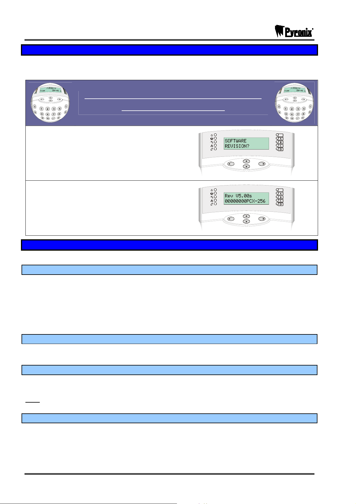
PCX SMS AND PCX 256 SYSTEM MANUAL
13.3 Software Revision
This option identifies the software version number, software serial number and product, and should always
be checked before contacting Customer Support.
Visual Keypad Programming Procedure
SOFTWARE REVISION?
Using the mand Pkeys, scroll to ‘SOFTWARE
REVISION?’
Press the Okey
The following will be displayed (on a PCX 256)
Press the Okey
You will be returned to the Engineer Menu.
13.4 Choose Mode
This option allows you to select the following options:
13.4.1 The End of Line Range
Please note this feature is not on the PCX 26/SMS
This programs the panel to operate with different resistor values:
1K1 = Alarm: 1K1, Tamper: 1K1.
2K2 = Alarm: 4K7, Tamper: 2K2.
4K7 = Alarm: 4K7, Tamper: 4K7.
13.4.2 SEOL or DEOL
This programs whether the alarm panel and any Remote Input Expanders will be used in Singe End of Line
(SEOL) or Double End of Line (DEOL) resistor mode. This is a global selection, including keypads, etc.
13.4.3 Input Response Time
This selects the time that a input trigger must be present before the system responds by generating an
alarm, and is programmable from 100ms (0.1 seconds) to 3000ms (3 seconds). This is a global selection.
Settings below 400ms or above 800ms do not comply with EN50131 (or BS4737), and are provided
Note:
purely for diagnostic purposes. Higher settings are more resistant to false stimuli.
13.4.4 Input XDF
DO NOT CHANGE THIS SETTING UNLESS INSTRUCTED TO BY CUSTOMER SUPPORT.
Page: 46 RINS871-3
Page 47

PCX SMS AND PCX 256 SYSTEM MANUAL
Visual Keypad Programming Procedure
CHOOSE MODE
Choose Mode
Using the mand Pkeys, scroll to ‘CHOOSE
MODE?’
Press the Okey
The End of Line Range
(NOT AVAILABLE IN PCX 26/SMS)
Enter : for 1K Range
Enter : for 2K2 Range
Enter #: for 4K7 Range
Press the Okey
NOTE: ONLY 4K7 RESISTORS CAN BE USED
UNTIL FURTHER NOTICE
The End of Line Mode
Enter : for SEOL (Single End of Line)
Enter : for DEOL (Double End of Line)
Press the Okey
The Input Response
Select the required input response – using
(100ms) all the way to (3000ms).
This should be left at default (400ms).
Press the Okey.
Input XDF
Enter : for Dyn Not Used
Enter : for Safe
Enter #: for Normal
NOTE: DO NOT CHANGE THIS SETTING
Press the Okey
You will be returned to the Engineer Menu.
RINS871-3 Page: 47
Page 48

PCX SMS AND PCX 256 SYSTEM MANUAL
13.5 Install RIX
Any Remote Input Expanders installed on the PCX system must be enabled by the ‘Install RIX’ function.
Please see the table on page Error! Bookmark not defined. on how many RIX’s you can install on your
system, for connection details please see Page: 125.
Visual Keypad Programming Procedure
INSTALL RIX
Install RIX
Using the mand Pkeys, scroll to ‘INSTALL RIX?’
Press the Okey
RIX Address
Please select the address for the RIX you are
installing and press the Okey
RIX Installed?
Enable/Disable the RIX that you have installed.
Enter : for NO
Enter : for YES
Press the Okey
RIX Address
Repeat for additional RIX’s or press the Pkey.
You will be returned to the Engineer Menu.
Page: 48 RINS871-3
Page 49

PCX SMS AND PCX 256 SYSTEM MANUAL
13.6 Change Inputs
By default, all inputs are pre-set as ‘unused’ so you will need to program each individual input you require.
The input will not be ‘live’ (and hence cannot be walk tested) until you have exited the Engineer Menu
(please see Page: 13)
Before programming, identify the location of each input from the following tables on page Error! Bookmark
not defined..
13.6.1 Input Types
Number & Type Operation
00 Unused
01 Fire
02 Gas
03 HU
04 Silent HU
05 Tamper
06 Immediate
07 Entry/Exit (EE)
08 Access (A)
09 A (Part EE)
10 EE (Part A)
11 PTS
12 Switcher
13 24 Hour
Factory default
Input is programmed out of operation.
Active at all times
Audible response: Full (differentiated).
Communicator: ‘Fire’ signal
Active at all times
Audible response: Full (differentiated)
Communicator: ‘Gas’ signal
Active at all times
Audible Response: Full (differentiated)
Communicator: ‘Hold Up’ and ‘Input HU’ signals
Active at all times
Audible Response: None
Communicator: ‘Hold Up’ and ‘Input HU’ signals
When disarmed:
Audible Response: Internal only
Communicator: ‘Tamper’ signal
When armed:
Audible Response: Full (differentiated)
Communicator: ‘Tamper’ and ‘Intruder’ signals
Active when armed
Audible Response: Full
Communicator: ‘Intruder’ signal
Active when armed – initiates entry timer if system not disarmed before entry
time expires:
Audible Response: Full
Communicator: ‘Intruder’ signal
Active when armed, except during entry time
Audible Response: Full
Communicator: ‘Intruder’ signal
When fully armed, acts as Access input, as above
When part armed, acts as Entry/Exit input, as above
When fully armed, acts as Entry/Exit input, as above
When part armed, acts as Access input, as above
Active during exit time to complete arming procedure
No audible or communicator response.
Note: May be used to act as ‘doorbell’ by use of ‘chime’ attribute.
Active at all times
No audible or communicator response
Triggers associated output or switches other equipment
When armed:
Audible Response: Full
RINS871-3 Page: 49
Page 50

PCX SMS AND PCX 256 SYSTEM MANUAL
Number & Type Operation
Communicator: ‘Intruder’ signal
When disarmed:
Audible Response: Programmable
Communicator: ‘Day Alarm’ signal
Sub Part
15
Control*
16 Fault
Closure
17
Supervision
18 Shunt Input*
19 Disarm Input*
Keyswitch
20
Latched
Entry Shock
21
Input
Keyswitch
23
Pulsed
Input is allocated by system software and cannot be reprogrammed to a different
type, though relevant attributes may be adjusted.
Active when armed or disarmed
Audible Response: Graduated internal
Triggers ‘Global Fault 1 and 2’ outputs if the system is armed.
Triggers ‘Global Fault 2’ output if the system is disarmed.
Active during arming procedure
No audible or communicator response
Prevents system being armed whilst active
Active at all times
No audible or communicator response
Accepts input from keyswitch (or equivalent) to shunt the inputs assigned to it.
Associated outputs are available.
After 10 seconds the detectors in the shunt list will be active.
Active when armed
Accepts input from keyswitch (or equivalent) to disarm the arm level assigned to it.
Accepts input from keyswitch (or equivalent) to arm/disarm the arm modes
assigned to it. Arming includes normal exit time, etc. This is latched.
Active when system armed
Works in conjunction with EE input type for detection of forced entry. See page 50
for details.
Accepts input from keyswitch (or equivalent) to arm/disarm the arm modes
assigned to it. This pulses the arm/disarm state.
NOTES:
‘Part Arm’ refers to any combination other than all available partitions
A trigger from an Access input will be stored for 2 seconds before an alarm is activated. If
an Entry/Exit input is triggered within this time, the system will select entry time, rather than
immediate alarm.
*Not available on the PCX 26/SMS
13.6.2 Entry Shock Input Type (21)
This input type is always used in conjunction with an Entry/Exit input. The EE input is a door contact on the
initial entry door, and the Entry Shock input is a non-latching shock sensor fitted to the door frame in the
vicinity of the lock.
If the initial entry door is subjected to gross attack and forced open, then at the expiry of entry time only one
further intruder input need to be activated to signal a sequentially confirmed alarm – the Entry Shock input
counts as the first to alarm.
The Entry/Exit door contact must be opened with 10 seconds of the shock detector triggering for the Entry
Shock response to apply. Triggering the Entry Shock input in isolation will NOT generate an alarm of any
kind.
Page: 50 RINS871-3
Page 51

PCX SMS AND PCX 256 SYSTEM MANUAL
13.6.3 Creating a Common Partition
Please ignore this section if you are using a PCX 26/SMS.
In certain situations, a ‘common’ partition may be needed.
A common partition is a partition that only arms if other specific partitions are armed. For example, a
reception in a building will only need to be armed if the offices and warehouse are armed. If the office is
armed, but the warehouse isn’t, then the reception would still need to be inactive so people would be able to
leave the premises. An example of how to set this up is as follows:
Office: Inputs 1, 2, 3 and 4.
Warehouse: Inputs 5, 6 and 7.
Reception: Input 8.
Therefore what we would need to do in the above situation is program the office in one partition (for example
Partition A) and program the warehouse in another partition (for example in Partition B). We then need to
make the Reception ‘common’ to these two areas (Partitions A and B), so we need to select both partitions A
and B for this input (input 8)
After selecting the partitions for each input there is an option called “Input Partition: Any/All”. For inputs
1,2,3,4,5,6 and 7 we need to make this attribute ‘any’, as they work independently to the partition they are
assigned to. For input 8 (The common partition), we need to make this attribute as ‘all’, therefore when
partitions A and B are both armed, the reception (input 8) will automatically arm as well. In this example, you
would also have to select the user codes to both partitions A and B (the keypads/readers can be in separate
partitions though).
13.6.4 Input Attributes
Attribute Response Modification
Chime
Single
Follow
System loudspeaker(s) will ‘chime’ when an input triggered whilst the alarm panel is
disarmed. Note: The input concerned will not indicate on the display.
System chimes once when the input is triggered.
System chimes until the input is cleared.
Applicable to Immediate, Entry/Exit and Access input types
Omittable
Double
Knock
Dual Trip
Normally
Open
*Monitor
Activity
*Special
Logged
*Paired
Input
Confirm
Group
Enables the input to be manually omitted during the arming procedure.
The control will only generate an alarm if this input is triggered twice within a (programmable)
pre-set period, or if the input remains in fault condition for that period.
The control will only generate an alarm if this input, and another like-programmed input with
adjacent number, are in fault condition at the same time. Either input in fault condition will
prevent the system from arming.
Enables the system to respond correctly when detectors of ‘normally open’ configuration are
wired to the system. Alternatively converts input types which default to ‘normally open’ (e.g.
PTS) to operate with normally closed devices.
Enables an input to generate an alarm if the input does not see any activity for a period
specified by the NAT (Non Activity Time) timer.
Forces a log entry when the input is opened or closed, even when an alarm does not result.
May be selected to apply when a system is armed, when disarmed, or always.
DO NOT USE THIS OPTION
If one or more inputs are selected within the same confirm group, all confirmed signals will be
disabled. If confirm group is selected as ‘00’ the inputs are not part of any group. If inputs are
allocated to group 99 they will generate an alarm that results in an intruder (unconfirmed)
signal to an ARC. They will not under any circumstances generate a confirmed signal,
regardless of which group the input that triggered the ‘unconfirmed’ alarm is allocated to.
Any input may be programmed with any combination of these attributes, except where stated.
RINS871-3 Page: 51
Page 52

PCX SMS AND PCX 256 SYSTEM MANUAL
* NOT AVAILABLE IN PCX 26/SMS.
Visual Keypad Programming Procedure
CHANGE INPUTS
Change Inputs
Using the mand Pkeys, scroll to ‘CHANGE
INPUTS?’
Press the Okey
Input
Select the input number you wish to program and
press the Okey.
Input Type
Select the input type (See the ‘input types’ table –
Page: 49) by using either the numeric code or the
^and`.
Input Partition
Enter the partitions/level arms you would like the input
to operate in (To select level arming instead of
partitions please refer to Site Options “Use Level
Arming”, see page: 84).
Example shows the PCX 256 system display.
Please note the primary partitions are A, B, C and D.
Press the Okey.
For partition arming systems only:
Enter : for Any
Enter : for All
Press the Okey
(Mainly used for common partition see page: 51)
Input Attributes
Press the O key to select any attributes for the input
(for details on each attribute see page: 51)
Page: 52 RINS871-3
Page 53

PCX SMS AND PCX 256 SYSTEM MANUAL
Chime
Enter : for Any
Enter : for Single
Enter #: for Follow
Press the O key
Omittable
Enter : for No
Enter : for Yes
Press the O key
Double Knock
Enter : for No
Enter : for Yes
Press the O key
Dual Trip
Enter : for No
Enter : for Yes
Press the O key
Normally Open
Enter : for No
Enter : for Yes
Press the O key
Monitor Activity (Not available on PCX 26/SMS)
Enter : for No
Enter : for Yes
Press the O key
Special Log (Not available on PCX 26/SMS)
Enter : for No
Enter : for Arm
Enter #: for Disarm
Enter : for Always
RINS871-3 Page: 53
Page 54

PCX SMS AND PCX 256 SYSTEM MANUAL
Paired Input (Not available on PCX 26/SMS)
Enter : for No
Enter : for Yes
Press the O key
Confirm Group
Enter the Confirm Group if used.
Press the O key
Input Name
If you would like to enter a name for the input, select
the O key.
Enter the text to identify the input. Text programming
is described on page: 42. Select the O key.
Repeat all the above for further inputs, or press the
Pkey to return to the Engineers Menu.
NOTE: After programming the inputs, it is necessary to exit the Engineer Menu for the programming
to take effect, before the inputs are walk tested, etc.
Page: 54 RINS871-3
Page 55

PCX SMS AND PCX 256 SYSTEM MANUAL
13.6.5 Shunt Inputs
A shunt group may consist of any number of inputs programmed as Immediate, Tamper, 24hr and Access
types. These must all be allocated in the same partition. NOTE: These will need to be programmed first.
A maximum of 13 shunt inputs can be programmed on the PCX 26/SMS and a maximum of 128 on the PCX
256 (i.e. half the number of inputs on the system).
The inputs in the shunt group/list will only activate after 10 seconds of the nominated shunt input. For
example, if input 1 is programmed as ‘Shunt Input’, and inputs 2 and 3 are programmed as “24hr”, then once
input 1 has been opened, after 10 seconds inputs 2 and 3 become active.
Action Status Outputs
Shunt Input closed (shunted)
Shunted Input triggered No response
Shunt Input opened
(unshunted)
After 10 seconds
Shunt Input opened with an
active detector (attempting to
unshunt)
Active input clears -
After 10 seconds
Shunted input triggered
(whilst not triggered)
Inputs within the shunt list are
inactive
-
Inputs in the shunt list are
active
-
Inputs in the shunt list are
active
Normal input response
The ‘Follow Input’ PGM output
live
The ‘Follow Input’ PGM output
clears. The ‘Shunt Fault’ PGM
output is live for 10 seconds.
Indications off.
The ‘Follow Input’ PGM output
clears. The ‘Shunt Fault’ PGM
output pulses until the shunt is
reset or the input fault clears.
The ‘Shunt Fault’ PGM output
is live for 10 seconds.
Indications off.
(Note: depends upon the
status of the partition in which
the shunt is located).
Visual Keypad Programming Procedure
CHANGE INPUTS
Shunt Inputs
Change Inputs
Using the mand Pkeys, scroll to ‘CHANGE
INPUTS?’
Press the Okey
Input
Select the input number you wish to program as the
shunt input. Press the Okey.
RINS871-3 Page: 55
Page 56

PCX SMS AND PCX 256 SYSTEM MANUAL
Input Type
Select the shunt input type (type 18)
Shunt Inputs
If you would like to select the shunt inputs for the
selected input press the Okey.
Enter the inputs you would like in the shunt list, after
each one press the Okey. Each input selected will
scroll on the display on the bottom line.
If the input you have selected doesn’t appear, make
sure that input is programmed correctly (Intruder,
Tamper, 24Hr or Access).
Once they have all been entered press the Pkey,
and press the Pkey again.
Input Partition
Enter the partitions/level arms you would like the input
to operate in (To select level arming instead of
partitions please refer to Site Options “Use Level
Arming”, see page: 84).
Example shows the PCX 256 system display.
Please note the primary partitions are A, B, C and D.
Press the Okey.
For partition arming systems only:
Enter : for Any
Enter : for All
Press the Okey
Input Attributes
Press the O key to select any attributes for the input
(for details on each attribute see page: 51)
Page: 56 RINS871-3
Page 57

PCX SMS AND PCX 256 SYSTEM MANUAL
Chime
Enter : for Any
Enter : for Single
Enter #: for Follow
Press the O key
Omittable
Enter : for No
Enter : for Yes
Press the O key
Double Knock
Enter : for No
Enter : for Yes
Press the O key
Dual Trip
Enter : for No
Enter : for Yes
Press the O key
Normally Open
If the shunt is normally open:
Enter : for No
Enter : for Yes
Press the O key
Monitor Activity (Not available on PCX 26/SMS)
Enter : for No
Enter : for Yes
Press the O key
Special Log (Not available on PCX 26/SMS)
Enter : for No
Enter : for Arm
Enter #: for Disarm
Enter : for Always
RINS871-3 Page: 57
Page 58

PCX SMS AND PCX 256 SYSTEM MANUAL
Paired Input (Not available on PCX 26/SMS)
Enter : for No
Enter : for Yes
Press the O key
Confirm Group
Enter the Confirm Group if used.
Press the O key
Input Name
If you would like to enter a name for the input, select
the O key.
Enter the text to identify the input. Text programming
is described on page: 42. Select the O key.
Repeat all the above for further inputs, or press the
Pkey to return to the Engineers Menu.
Page: 58 RINS871-3
Page 59

PCX SMS AND PCX 256 SYSTEM MANUAL
13.7 Assign Keypads/Readers
Ensure that all keypads and readers are addressed correctly before enabling them in this function. Please
see page 121 on how to address each individual keypad and reader.
13.7.1 Reader Is:
This option will only appear when you program a Reader into the system. You can then select how you
would like the Reader to operate.
Arm Point: This will make the Reader act like a normal keypad (arming/disarming the system etc)
*S/Part Control: A reader can be used to create sub-partitions. For example: A keypad may control a full
area, but in the partition you may wish to control certain inputs only, thus you can arm/disarm those inputs
only via the reader.
*Access Control: If an access control system is installed then you will need to program the reader as this
type.
Disarm Only: If you wish to use the Reader to disarm the system only, select this type.
Please also note that any RIX2s on the system will need to be programmed as a ‘Reader’.
*Not available on PCX 26/SMS
13.7.2 Arm Point Arms
An “Arming Point”, this means that you can program the keypad / reader to arm certain partitions only. This
is used in conjunction with the partitions allocated to a user code.
For example, if a user code is programmed to operate partitions ‘A’ and ‘B’, but the keypad / reader is only
programmed to arm Partition ‘A’, then the system will arm only partition ‘A’.
13.7.3 Arm Point Disarms
A “Disarming Point” means that you can program the keypad / reader to disarm certain partitions only. This is
used in conjunction with the partitions allocated to a user code.
For example, if a user code is programmed to operate partitions ‘A’ and ‘B’, but the keypad / reader is only
programmed to disarm Partition ‘A’, then the system will disarm only partition ‘A’.
13.7.4 Arm Point In
When arming from a keypad / reader located in the partition being armed, the programmed exit mode and
exit time will apply.
When arming from a keypad / reader that is NOT located in the partition being armed, the system will ‘quick
arm’ the partition. This will not apply to arming of partition B as part of a ‘Full’ system arm if ‘intelligent
arming’ is enabled.
For example, if a user code is programmed to operate partition ‘B’, but the ‘Arm Point In’ for the keypad /
reader is only programmed for partition ‘A’, then once the user code is entered, partition ‘B’ will quick arm.
Otherwise the system will operate as normal depending on the exit mode and exit time.
On the PCX 26/SMS system you will only select one level arm under ‘Default Level’, this selects what
the “default arm mode” will be set to (A,B,C or D). Arm point arms, disarms and point in is only on
the PCX 256
RINS871-3 Page: 59
Page 60

PCX SMS AND PCX 256 SYSTEM MANUAL
Visual Keypad Programming Procedure
ASSIGN KEYPADS/READERS
Assign Keypads/Readers
Using the mand Pkeys, scroll to ‘ASSIGN
KEYPADS/READERS?’
Press the Okey
Address
Enter the address of the keypad/reader you wish to
assign. Press the Okey
Type
Enter : for Keypad
Enter : for Reader
Enter #: for Not Used
Press the Okey
NOTE: This function will only be displayed if you
have programmed a Reader.
Reader Is
Enter : for Arm Point
Enter : for S/Part Control*
Enter #: for Access Control*
Enter : for Disarm Only
*Not available on PCX 26/SMS
Press the Okey
Arm Point Arms
Select the Arm Points you would like for ‘arming’ the
system. Press the Okey
NOTE: The partition options will change
depending on the system you are using.
Please note the primary partitions are A,B,C and D.
‘Default Level’ will be displayed on the PCX 26/SMS;
you need to select which arm mode you would like to
be automatically selected initially. Arm Point Name
will then be displayed.
Page: 60 RINS871-3
Page 61
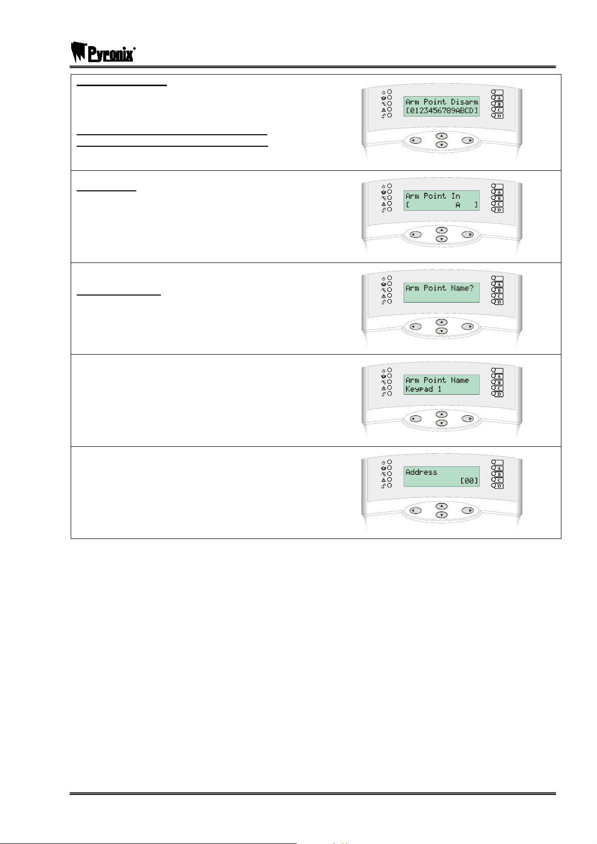
PCX SMS AND PCX 256 SYSTEM MANUAL
Arm Point Disarms
Select the Disarm Points you would like for
‘disarming’ the system. Press the Okey
NOTE: The partition options will change
depending on the system you are using.
Please note the primary partitions are A,B,C and D.
Arm Point In
Select the Arm Point Level/Partition.
Press the Okey
Please note the primary partitions are A,B,C and D.
Arm Point Name?
If you would like to select an arm point name press
the Okey.
Enter the text to identify the arm point. Text
programming is described on page 42.
Repeat for all other keypads/readers or press the
Pkey to exit. You will be returned to the Engineer
Menu.
RINS871-3 Page: 61
Page 62

PCX SMS AND PCX 256 SYSTEM MANUAL
13.7.5 Access Control
The following programming shows how to set up the Access Control facility if you are using it. For connection
details please see page: 138. This is not available on the PCX 26/SMS.
Visual Keypad Programming Procedure
ASSIGN KEYPADS/READERS
Access Control
Assign Keypads/Readers
Using the mand Pkeys, scroll to ‘ASSIGN
KEYPADS/READERS?’
Press the Okey
Address
Enter the address of the keypad/reader you wish to
assign. Press the Okey
Type
Enter : for Reader
Press the Okey
Reader Is
Enter #: for Access Control
Press the Okey
Enter the Lock Open Time (max: 250 seconds).
This is the time the door release is going to be active
when a valid tag’s presented.
Press the Okey.
Enter the Door Open Time (max: 250 seconds).
This is the time the door is allowed to be open before
triggering an alarm.
Press the Okey.
Page: 62 RINS871-3
Page 63

PCX SMS AND PCX 256 SYSTEM MANUAL
Enter the input number to monitor the chosen door.
Please note that this must be selected for the door
monitoring to function.
Entering ‘999’ disables the monitoring for this door.
To enter a personal name for the access control,
press the Okey. Use the text programming to enter
this, see page: 42.
Press the Okey, you will be returned to the engineer
menu.
Door Monitoring Facility
If the door is to be monitored by the alarm system only, the door monitoring input should be wired direct to
the end station (not via the door station) and programmed appropriately (see table below).
If the door is to be monitored by the door station only (providing local alarm), the door monitoring input
should be wired as page 138, and should be programmed as omitted in ‘Change Inputs’ menu. The ‘Door
Contact No.’ should be an input number that is unused on the system.
If the door is to be monitored by the door station and the end station, the door monitoring input should be
wired as page 138, and be programmed in the ‘Change Inputs’ menu (see table below). The ‘Door Contact
No.’ should correspond to this input.
Input Type
Valid door open (i.e. valid tag or
‘request to exit’)
Door forced (i.e. no valid tag,
nor ‘request to exit’)
Final Exit Starts entry time, if system armed Day alarm
Switcher No response Day alarm
All other types No response Normal input response
NOTES: If input is programmed as ‘isolated’ then monitoring will be SOLELY at the door station. If the input
is to be monitored by the alarm system ONLY, it should be wired directly to the system, and NOT via the
door station.
RINS871-3 Page: 63
Page 64

PCX SMS AND PCX 256 SYSTEM MANUAL
13.8 System Displays
Please see page 42, “Text Programming” section for this function as it requires programming partition text,
sign on messages etc.
13.8.1 Partition Texts
You may choose how you want each Partition/Level Arm to be displayed, i.e. “Partition A” may be used to
fully arm a house therefore you may want to call it “Full House Arm” for example. You can have a maximum
of 16 characters on the display.
13.8.2 Sign On Message
The Sign on Message is the main display on the top line in disarmed mode.
13.8.3 Site Name
The Site Name is used as a “Site Reference” which if used must be also used within the PCX
Upload/Download Software in order for the software to connect to the PCX system.
13.8.4 Display When Arm
If this option is enabled, then the Partition Text will be displayed on the LCD keypad once the system is fully
armed. This option is not available on the PCX 26/SMS.
Visual Keypad Programming Procedure
SYSTEM DISPLAYS
System Displays
Using the mand Pkeys, scroll to ‘SYSTEM
DISPLAYS?’
Press the Okey
Partition Text
Enter the desired text for the partition; press the
Okey to enter the text for all other partitions. You
can also add/change the text for “Full” partition
arming, the sign on message and the site name label.
Press the Okey once you have changed each text
display.
Display When Arm
Enter : for No
Enter : for Yes
Press the Okey.
You will be returned to the Engineer Menu.
Page: 64 RINS871-3
Page 65

PCX SMS AND PCX 256 SYSTEM MANUAL
13.9 Change Timers
All the timers can be changed in this function, the table below shows the different timers available and the
default values:
Timer Function Range
Entry Time
Exit Time
Bell Time
Confirm Time
Bell Delay
Strobe Time
Re-Arm No.
AC Signal
Delay
Speaker
Final Exit
Delay
Double Knock
Pre-Alarm
Entry time for each partition. 0 – 255 seconds
Exit time for each partition. 0 – 255 seconds
Cut off time for external sounder. Separate for each partition. 2 – 15 minutes
Time period during which a second activation must occur to qualify
as ‘sequentially confirmed’ alarm. NOTE: DD243 specifies a
confirm time between 30 and 60 minutes. This also can be used
in conjunction with testing an omit signal.
Delay after intruder alarm before bell live. NOT valid within 3
minutes of final arm, after entry time started.
Time strobe output remains live after bell time ends.
‘99’ means endless.
Number of times system re-arms after bell time ends.
NOTE: Re-arm number applies to each partition, and does not
affect emergency alarms. ‘9’ means always re-arm.
Time delay before mains failure or technical alarm signalled.
NOTE: Arming ‘250’ = never alarms. System change-over to
battery supply and associated visual ‘Mains Fail’ indication is
always immediate.
Time speaker and keypad bleeper outputs remain live after
bell time ends. ‘99’ means endless.
Time between final exit input closing, and system arming.
Length of filter period applied to inputs with ‘Double Knock’
attribute.
Delays ‘Intruder’ output signals if entry time has started.
Not required for compliance with ARCO policy / DD243.
NOTE: This must be set to 30 seconds to comply with PD6662
1 – 99 minutes
0 – 20 minutes
0 – 99 minutes
0 – 9
0 – 250 minutes
0 – 250 minutes
0 - 255 seconds
0 – 75 seconds
0 – 255 seconds
Line Fault
Arm Fail
Guard Code
Alarm
Fire Bell Time
*Input NAT
Days
*Input NAT
Hours
NOTE: Control of timer for inputs on arm fail test is located in the Engineer Tests Sub Menu
* NOT AVAILABLE ON PCX 26/SMS
RINS871-3 Page: 65
Duration of Telecom Line Fault before ‘Line Fault’ alarm triggered. 0 – 250 seconds
Time after which ‘Arm Fail’ operation will be invoked if exit
procedure not completed.
Minimum time an alarm must have existed before a ‘Guard’ code
will be accepted to disarm.
Cut off time for fire alarm
‘99’ means endless.
NAT stands for Non-Activity. This is used in conjunction with the
input attribute ‘Monitor Activity’, and will monitor the chosen input
for the selected number of days.
NAT stands for Non-Activity. This is used in conjunction with the
input attribute ‘Monitor Activity’, and will monitor the chosen input
for the selected number of hours.
0 – 255 seconds
0 – 10 minutes
1 – 99 minutes
0-14
00-23
Page 66

PCX SMS AND PCX 256 SYSTEM MANUAL
Visual Keypad Programming Procedure
CHANGE TIMERS
Change Timers
Using the mand Pkeys, scroll to ‘CHANGE
TIMERS?’
Press the Okey
Timers
The timers as displayed in the table on the previous
page will be displayed, adjust the time as required
and press the Okey. Once you have finished, press
the Pkey, you will be returned to the Engineer
Menu.
13.10 Set Time and Date
All log entries and the system display include the time and date. This may be also programmed in the Master
Manager Mode.
NOTE: Please note that powering down the PCX system will reset the time and date information.
Visual Keypad Programming Procedure
SET TIME & DATE
Set Time & Date
Using the mand Pkeys, scroll to ‘SET TIME &
DATE?’ Press the Okey
Year
Adjust the year as required using the numeric keys
Press the Okey
Month
Adjust the month using the numeric keys
Press the Okey
Page: 66 RINS871-3
Page 67

PCX SMS AND PCX 256 SYSTEM MANUAL
Day
Adjust the day using the numeric keys
Press the Okey
Hours
Adjust the hours using the numeric keys
Press the Okey
Minutes
Adjust the minutes using the numeric keys
Press the Okey
You will be returned to the Engineer Menu.
13.11 Exit Modes
13.11.1 Timed
The PCX system will only arm when the programmed Exit Time has expired (See ‘Change Timers’ page 66)
providing that all inputs are closed.
13.11.2 Final Door
The PCX system will only arm when an input programmed as Entry/Exit (EE) is either closed (if the input was
opened when arming started) or its single opening and then closing (if the input was closed).
This mode may also be used for ‘lock arm’ operation: securing the lock completes the arming procedure,
unlocking starts the entry time.
13.11.3 Timed/Final
This function follows ‘timed’ operation, except that the timer will be overridden if an Entry/Exit input is opened
and closed before the timer expires (See above: Final Door).
13.11.4 PTS (Push To Set)
PTS = Push to Set. The PCX system will only arm when a ‘Push to Set’ button has been pressed. This
function will override the programmed Exit Time.
Visual Keypad Programming Procedure
EXIT MODES
Exit Modes
Using the mand Pkeys, scroll to ‘EXIT MODES?
Press the Okey
RINS871-3 Page: 67
Page 68

PCX SMS AND PCX 256 SYSTEM MANUAL
Enter : for Timed
Enter : for Final Door
Enter #: for Timed/Final
Enter : for Push To Set
Press the Okey
Repeat for each partition or press the Pkey to return
to the Engineer Menu.
13.12 Change Codes (Duress/Guard Only)
All codes may be 4, 5, or 6 digit or proximity tags. Using a 5 or 6 digit code will automatically block several
possible 4 digit codes that clash with it. Please note that the PCX System will only comply with Grade 3 if
you have “5 digit codes” enabled.
NOTES: Only Duress or Guard codes can be changed by the Engineer, Normal user codes can only
be changed in The Manager Mode. See page: 40. The Master User and Engineer Codes cannot be
deleted.
13.12.1 Code Types and Numbers.
PCX System User/Manager Codes Duress/Guard Codes
PCX 26/SMS 20 10
PCX 256 500 20
13.12.2 User Types
User Type Functions Operation
User
Default: 1234
Manager
Manager Manager
Default: 5678
Engineer
Default: 9999
Duress
Guard
Arm and Disarm System
Also for Access Control and Sub Partition Control
functions
Arm and Disarm System
Also access to Manager menu functions
Arm and Disarm System.
Also access to Manager menu functions
Access to all engineering functions, also
arm/disarm system for test purposes.
Disarm system, generating silent ‘Duress’ or ‘Hold
Up’ signal
Disarm system, but only after an alarm has been
active for a minimum time (programmable). Also
arm system. An output type is available to signal
whenever this code is used.
Programmed by
Manager only.
Programmed by
Manager only.
Programmed by
Manager or Engineer.
Programmed by
Engineer.
Programmed by
Engineer.
Programmed by
Engineer.
13.12.3 User Arm Options
The User Codes can be programmed as the following:
Disarm/Arm: The code will arm and disarm the PCX system
Disarm Only: The code will only disarm the PCX system once it is fully armed.
Arm Only: The code will only arm the PCX system.
None: The code will not be used to arm and disarm the system.
Page: 68 RINS871-3
Page 69

PCX SMS AND PCX 256 SYSTEM MANUAL
13.12.4 Flexi Arm
If enabled, the user will be able to select which partitions they can arm/disarm, from those the code is valid
for. If disabled, the user code will automatically arm in the selected partition(s). This option is commonly
used if a proximity tag has been used on the system.
Visual Keypad Programming Procedure
CHANGE CODES
Change Codes
Using the mand Pkeys, scroll to ‘CHANGE
CODES? Press the Okey
5 Digit Pins
Enter : for No
Enter : for Yes (Grade 3)
Press the Okey
Change Duress Codes
Press the Okey to Change the Duress Codes, or for
the next function press the Pkey.
Duress Codes
Enter the required User Number using the numeric
keys.
Press the Okey
If a code or tag is already allocated, the display will
show [******]. Enter the new code, or present a
tag to keypad. To erase the existing code press the
n key. Press the Okey
User Type
Enter #: for Duress
Enter : for Guard
Press the Okey. (User codes can only be
changed in the user manager mode)
RINS871-3 Page: 69
Page 70

PCX SMS AND PCX 256 SYSTEM MANUAL
User Partitions
Select the partitions the code will be valid for.
Please note that the partitions will change depending
on the PCX system.
Please note the primary partitions are A,B,C and D.
Press the Okey
User Arm Options
Enter : for Disarm/Arm
Enter : for Disarm Only
Enter #: for Arm Only
Enter : for None
Press the Okey
Flexi Arm
Enter : for No
Enter : for Yes
User Name
Enter the text to identify the user. Text Programming
is described on page 42.
Change Master Manager Code?
Press the Okey to Change the Duress Codes, or for
the next function press the Pkey.
The Master Manager Code cannot be deleted
Enter the new code.
Press the Okey if you wish to change the Master
Manager Code.
Select the partitions the code will be valid for
Press the Okey
Please note that the partitions will change depending
on the PCX system.
Please note the primary partitions are A,B,C and D.
Page: 70 RINS871-3
Page 71

PCX SMS AND PCX 256 SYSTEM MANUAL
User Arm Options
Enter : for Disarm/Arm
Enter : for Disarm Only
Enter #: for Arm Only
Enter : for None
Press the Okey
Flexi Arm
Enter : for No
Enter : for Yes
Press the Okey
User Name
Enter the text to identify the user. Text Programming
is described on page: 42
Press the Okey
Press the Pkey
Press the Oif you wish to change the Engineer
Code.
The Engineer Code cannot be deleted.
Enter the code. Press the Okey.
Press the Pkey.
You will be returned to the Engineer Menu.
RINS871-3 Page: 71
Page 72

PCX SMS AND PCX 256 SYSTEM MANUAL
13.13 Volume Control
The Volume Control function applies to the loudspeaker output only. Volume levels at the keypad are
programmed individually – please see page: 41.
13.13.1 Code Stops Sound
If this function is enabled, then once an alarm has been generated (even if the code is not programmed for
that partition) the alarm will be silenced, and a ‘Misoperation (Abort) signal’ will be sent, but the partition will
still be armed until a valid user that controls that partition is entered.
13.13.2 E / E Keypads Only
If there is a speaker connected to the SPK output of the PCX system the entry and exit tones will be heard
through the speaker. If you would like Entry and Exit tones to be heard on only the keypad and not the
speaker then enable this function.
13.13.3 Alert Kps Only
If this function is enabled then any Alert tones will be heard on the Keypad only and not the speaker.
Visual Keypad Programming Procedure
VOLUME CONTROL
Volume Control
Using the mand Pkeys, scroll to ‘VOLUME
CONTROL? Press the Okey
Partition Volume
Use the numeric keys select the volume level required
for Entry and Exit tones for each partition, once
selected, press the Okey to go to the next.
Alarm
Use the numeric keys to select the volume level
required for Alarm Tones
Press the Okey
Repeat for Fire, Tamper, Disarmed, Chime and
Intelligent Arm tones. Press the Okey
Code Stops Sound
Enter : for No
Enter : for Yes
Press the Okey
Page: 72 RINS871-3
Page 73

PCX SMS AND PCX 256 SYSTEM MANUAL
E/E Keypads Only
Enter : for No
Enter : for Yes
Press the Okey
Alert Kps Only
Enter : for No
Enter : for Yes
Press the Okey
You will be returned to the Engineer Menu
13.14 Alarm Response
The Alarm Response function controls how you would like certain activations to perform.
13.14.1 Silent 1st Alarm
If this function is selected as ‘confirmed’, then the first alarm to activated on the system will be silent, but the
if another input activates (i.e. a confirmed alarm) then the alarm will activate and the alarm tones will be
heard.
This option is only valid once the system has been set for 3 minutes and not if the entry time has started.
13.14.2 Disable Confirm On Entry
To comply with DD243 standards, the PCX system can be programmed so that confirmation signals are not
sent during the entry time.
If ‘Disable Confirm On Entry’ is set to YES this option will disable ALL
If ‘Disable Confirm On Entry’ is set to NO the confirmation signals are enabled on expiry of the entry time.
confirmation signals on entry.
13.14.3 Inputs to Confirm After Entry
This function accepts a choice of 1 or 2 inputs to trigger after expiration of entry time to qualify as a
sequentially confirmed alarm. Note: Only the “2” setting complies with DD243:2004.
13.14.4 Alarm Starts / Stops (Alarm Responses)
The order of which alarm responses are activated can be programmed to your requirements. The alarm
activations you can program are: Partitions, Fire, Gas, Hold Ups, and Disarm Alarms and the different alarm
responses are: Keypads, Internal Sounders, Bells Only, Digi and Confirm. The different alarm responses
work in a table format (the first in the list is ‘Keypads’ and the last being ‘Confirm’).
Each alarm response will take 15 seconds before moving on to the next response.
For example, If the alarm response for Partition A starts at ‘keypads’ and stops at ‘Digi’, then once Partition
A is armed and an alarm has been activated, the keypads will be first to activate, then after 15 seconds the
internal sounders, then after another 15 seconds the Bells will activate (Bells Only) and then after another 15
seconds the ‘Digi’ will activate, after this it will stop and you will get no confirm signal. If you ‘stopped’ at
‘Bells Only’ then any signalling will be disabled (Digi)
You may also program the system to operate on a combined partition basis, for example if both partitions ‘A’
and ‘B’ are armed; you may want the process of the alarm responses to change. Therefore you would use
the ‘If partitions armed’ section of this function and select the desired partitions and the alarm responses.
Another example of where this function would become useful is when you have several inputs programmed
as ’24 hour’, you may want the system to only activate the internal sounders in disarmed mode, but when the
system is armed you may want both the internal and external sounders to activate. To do this, when you get
to “Disarmed Starts”, enter ‘1’ for Internal Sounders and press function. “Disarmed Stops” will be displayed,
RINS871-3 Page: 73
Page 74

PCX SMS AND PCX 256 SYSTEM MANUAL
as you do not wish anything else to activate when the system is disarmed, enter ‘1’ for Internal Sounders
again. This will make the system only ever activate the internal sounders when an alarm has activated in
disarmed mode.
Visual Keypad Programming Procedure
ALARM RESPONSE
Alarm Response
Using the mand Pkeys, scroll to ‘ALARM
RESPONSE? Press the Okey
Silent 1st Alarm
Enter : for Never
Enter : for Confirmed
Press the Okey
Disable Confirm On Entry
Enter : for No
Enter : for Yes
Press the Okey
Inputs to Confirm After Entry
Enter the number of inputs to Confirm after the Entry
Press the Okey
Partition Starts
Enter : for Keypads
Enter : for Internal Sounders
Enter #: for Bells Only
Enter : for Digi
Enter : for Confirm
Press the Okey
Page: 74 RINS871-3
Page 75

PCX SMS AND PCX 256 SYSTEM MANUAL
Partition Stops
Enter : for Keypads
Enter : for Internal Sounders
Enter #: for Bells Only
Enter : for Digi
Enter : for Confirm
Press the Okey
Repeat the above 2 steps for each partition, and also
for Fire, Gas, HU and Disarm alarms
Press the Okey
You will be returned to the Engineer Menu
13.15 Change Outputs
Any output type may be programmed to any of the systems PGMs. PGMs must be used within their rated
capacity. See page: 23.
NOTE: The PGM Outputs CANNOT
be inverted.
13.15.1 PGM Output Types
Type Active Restore
0000 Not Used
0001 Fire
0002 Hold Up Any
0003 Intruder Any
0004 Final Arm All*
0005 Misoperation Any (Abort)
0006 Confirmed Any
0007 Tamper Any
0008 Duress
0009 HU Device Any
0010 Gas
0011 Arm Fail
0012 Entry Deviation
0013 Secure Intruder Any
0014 Bell Any
0016 Strobe Any
0017 Omit Rearm Any
At alarm When a valid code is entered
At a HU or Duress alarm
(This includes keypad HU)
At alarm, while system is
disarmed
When system is FULLY armed At code entry to disarm
When system is silenced after
any ‘intruder’ output is
triggered
When further input active in
any partition after ‘intruder’
alarm
Any tamper alarm At code entry to silence
At a Duress alarm (i.e. from a
keypad)
At alarm on a HU input only When a valid code is entered
At alarm When a valid code is entered
Pre-set time after start of exit
time, if exit procedure is not
complete
When deviation from entry
route occurs, during entry time
At alarm, after exit time started,
until disarm
When alarm live
When alarm live
At rearm at end of confirm time
if an input in fault is isolated
When a valid code is entered
At first valid code entry
After 2 minutes
At next code entry
When a valid code is entered
At code entry to rearm
At code entry to disarm
At first valid code entry
When alarm silenced or when
siren timer expires
When alarm silenced or when
strobe timer expires
When system disarmed
RINS871-3 Page: 75
Page 76

PCX SMS AND PCX 256 SYSTEM MANUAL
Type Active Restore
0018 Unconfirmed Any
0019 Can All Arm*
0020 Exit Starts All*
Any intruder or Tamper alarm At code entry to silence
If all inputs and technical faults
in system are clear. Also once
entry time has started
At start of exit time to arm
LAST partition
If fault exists, and after final
arm
At code entry to disarm FIRST
partition (i.e. no longer fully
armed)
NOTE: For ‘exit starts’ to be entered in system logs, the site option ‘Confirmed when…’ must be
set to ‘exit start’
0021 Exit Starts Any
0022 Final Arm Any
0023 Strobe Set Fail
0025 Keyswitch unset
0026
Set with Omit (Not on
PCX 256)
0031 Entry*
0032 Exit*
0033 Entry/Exit
0034 Lights
0035
Follow Input*
See page: 81.
When exit time starts to arm
FIRST partition
When FIRST partition is armed
Works similar to output 016, but also fires if the set fail timer
expires.
This output turns on for 5 seconds when the system is disarmed
via a keyswitch input (either pulsed or latched keyswitch)
Activates when inputs are omitted on an arming mode
Live during any exit time
Live during any entry time
Live during any entry or exit time
When exit or entry timer starts
When input triggers Dependant upon programming
At code entry to disarm LAST
partition
At code entry to disarm LAST
partition
20 seconds after arm/disarm
procedure completed
0036 Shunt Fault* See Shunt Inputs - Page: 55
0037 Reset 1 (Viper Reset)
0038
Reset 2 (Viper
Arm/Disarm)
0039 PIR Latch 1
0040 PIR Latch 2
0041 Mains Good
At code entry to arm After 3 seconds
At code entry to arm When disarmed
Re-triggers whenever an additional partition is armed
When armed (and in Walk
Test)
At alarm, or when disarmed
This is the inverse polarity to PIR Latch 1
Output showing the mains is healthy
This output activates during walk test and also when a code is
0042 Detr Indn Enable*
entered to view indications – staying activated for the time for
which the indications are viewed.
0043 Follow Test
0044 Off During Test
0051 Telecom Line Fault
0052 AC Fail
0053 Battery Faults
0054 Low Volts
New output for alternative bell test by activating SAB
New output for alternative bell test by activating SAB
When Line Fault signalled by
communicator
After pre-set time without
mains power
When battery disconnected or
load fail detected
When fault clears
On restoration of mains
At next valid code entry
At fault When fault clears
Activates if fault occurs only
0055 Global Fault 1
when system is armed (Faults:
Modem, Battery, Fuse, Line,
When all faults cleared
Mains)
Activates if fault occurs at any
0056 Global Fault 2
time (Faults: Modem, Battery,
When all faults cleared
Fuse, Line, Mains)
0057 German Relay*
0058 Guard Code Used
When ‘guard’ code accepted After 60 seconds
Page: 76 RINS871-3
Page 77

PCX SMS AND PCX 256 SYSTEM MANUAL
Type Active Restore
0059 Engineer Access
0060 Initialise Digi
When entering Engineer Mode When leaving Engineer Mode
At power up Live for 45 seconds only
Test signalling through
PSTN and GSM. Activates
0063 Test ATE/GSM*
when a test call is
When test completed
sent.(used for specific
GSMs)
Test signalling through
0064 Test ATS
0066 ATE not used
A repeating block of output types should be noted:
0202 Hold Up A
0203 Intruder A
0204 Final Arm A
0207 Tamper A
0208 Duress A
0209 HU Device A
0213 Secure Intruder A
0214 Bell A
0216 Strobe A
0217 Omit At Rearm A
0218 Unconfirmed A
0219 Can Arm A
0220 Exit Starts A
Then this pattern repeats for each other partition, so that:
0221-0240 Partition / Arm Level B 0361-0380 Partition / Arm Level 4*
0241-0260 Partition / Arm Level C 0381-0400 Partition / Arm Level 5*
0261-0280 Partition / Arm Level D 0401-0420 Partition / Arm Level 6*
0281-0300 Partition / Arm Level 0* 0421-0440 Partition / Arm Level 7*
0301-0320 Partition / Arm Level 1* 0441-0460 Partition / Arm Level 8*
0321-0340 Partition / Arm Level 2* 0461-0480 Partition / Arm Level 9*
0341-0360 Partition / Arm Level 3*
1xxx Follow input xxx
i.e. add 1000 to the input number to select output required
Partition Sounder At output 2 of the RIX2 (fixed as loudspeaker)
PSTN and GSM. Activates
when a test call is sent.
Makes the ATE pin 5V.
As 0002 for Partition A / Arm Level A events only
As 0003 for Partition A / Arm Level A events only
As 0004 for Partition A / Arm Level A events only
As 0007 for Partition A / Arm Level A events only
As 0008 for Partition A / Arm Level A events only
As 0009 for Partition A / Arm Level A events only
As 0013 for Partition A / Arm Level A events only
As 0014 for Partition A / Arm Level A events only
As 0016 for Partition A / Arm Level A events only
As 0017 for Partition A / Arm Level A events only
As 0018 for Partition A / Arm Level A events only
As 0019 for Partition A / Arm Level A events only
As 0020 for Partition A / Arm Level A events only
When input is activated When input clears
When test completed
*NOT AVAILABLE ON PCX 26/SMS
For the defaults please see page: 78
RINS871-3 Page: 77
Page 78

PCX SMS AND PCX 256 SYSTEM MANUAL
13.15.2 STU / ATE Pin Outputs (Defaults)
Any communicating device with the industry standard footprint may be plugged onto the control panel STU /
ATE (Alarm Transmission Equipment) pins. The default types for the footprint are as follows:
COM LOOM Default Type (PCX 26/SMS) Default Type (PCX 256)
1 (Blue)
2 (Orange)
3 (Yellow)
4 (Brown)
5 (Purple)
6 (Green)
7 (Black)
8 (Purple)
9 (White)
10 (Light Grey)
NOTE: There is an “output invert” option for use with positive removed signalling. Insufficient
current is available for any other application. Please see ‘Site Options’, page 84.
For programming on the STU / ATE pins please see page 79.
Unconfirmed Any (0018) Unconfirmed Any (0018)
Please see page 119 for the connection.
Fire (0001) Fire (0001)
HU Device Any (0009) HU Device Any (0009)
Final Arm Any (0022) Final Arm Any (0022)
Tamper Any (0007) Tamper Any (0007)
Confirmed Any (0006) Confirmed Any (0006)
Omit Rearm Any (0017) Omit Rearm Any (0017)
Global Fault 2 (0056) AC Fail (0052)
Global Fault 1 (0055) Global Fault 2 (0056)
Test ATS (0064) Test ATS (0064)
13.15.3 Digi Channel Outputs
The on-board digital communicator uses the following default PGM types:
Channel Default Type (PCX 26/SMS) Default Type (PCX 256)
1
2
3
4
5
6
7
8
9
10
For programming on the Digi Channels please see page 98.
Fire (PGM 0001) Fire (PGM 0001)
HU Device Any (PGM 0009) HU Device Any (PGM 0009)
Unconfirmed Any (PGM 0018) Unconfirmed Any (PGM 0018)
Final Arm Any (PGM 0022) Final Arm Any (PGM 0022)
Tamper Any (PGM 0017) Tamper Any (PGM 0007)
Confirmed Any (PGM 0006) Confirmed Any (PGM 0006)
Omit Rearm Any (0017) Omit Rearm Any (0017)
AC Fail (0052) AC Fail (0052)
Global Fault 1 (0055) Global Fault 2 (0056)
Test ATS (0064) Test ATS (0064)
13.15.4 PCX-PROX/EXT PGM Output
The RED LED on the PCX-PROX/EXT can be programmed so that it follows an output.
To achieve this, go to ‘CHANGE OUTPUTS’ and then ‘Reader PGMs’ and program the first PGM output
(PGM1) to whichever type is required.
For example you may want the Prox to show the system armed, therefore you can use the output “0204:
Final Arm A”. The RED LED will then be illuminated once Partition A has armed.
Page: 78 RINS871-3
Page 79

PCX SMS AND PCX 256 SYSTEM MANUAL
Visual Keypad Programming Procedure
CHANGE OUTPUTS
Change Outputs
Using the mand Pkeys, scroll to ‘CHANGE
OUTPUTS?’ Press the Okey
Endstation PGMs
To program the control panel PGMs and the
STU/ATE pins press the Okey.
PGMS
Select the output type for the PGMs and press the
Okey. Repeat for each PGM.
ATE PINS
When the display shows “ATE pin” you can decide
what you would like the STU / ATE pins to be
programmed as. Select the output type for the ATE
pin and press the Okey. Repeat for each pin.
RIX PGMS
Once you return to the sub-menu ‘Endstation PGMs’
press the Pkey, the display will show ‘RIX PGM’s’,
press the Okey.
Enter the address of the RIX. Press the Okey.
RINS871-3 Page: 79
Page 80

PCX SMS AND PCX 256 SYSTEM MANUAL
Select the output type for the PGMs and press the
Okey. Repeat for each PGM (and RIX address once
you have pressed the P key)
ROX PGMS
Once you return to the sub-menu ‘RIX PGMs’ press
the Pkey, the display will show ‘ROX Module
PGMs’, press the Okey if you have a ROX module
installed.
ROX Installed?
Enter : for No
Enter : for Yes
Press the Okey.
Select the output type for the PGMs and press the
Okey. Repeat for each PGM (and ROX address
once you have pressed the P key)
Keypad PGMs?
Repeat for the Keypad PGMs. Press the Pkey
Reader PGMs?
Repeat for the Reader PGMs. Press the Pkey. You
will be returned to the Engineer Menu.
Page: 80 RINS871-3
Page 81

PCX SMS AND PCX 256 SYSTEM MANUAL
13.15.5 The ‘Follow Input’ PGM
If the expander card is installed the PGM output ‘Follow Input’ is made available. This output provides the
following functionality:
¾ Follow (whilst input active), TIMED or LATCHED output
¾ Follow individual INPUT, PARTITION, SUB PARTITION or SHUNT LIST
¾ Follow WHEN ARMED, WHEN DISARMED or ALWAYS
NOTE: The Follow Input type WILL NOT function correctly if assigned to ATE pins.
Visual Keypad Programming Procedure
CHANGE OUTPUTS
Follow Input
Change Outputs
Using the mand Pkeys, scroll to ‘CHANGE
OUTPUTS?’ Press the Okey
Endstation PGMs
To program the control panel PGMs and the
STU/ATE pins press the Okey.
Select the output as type ‘0035’ = Follow Input.
Press the Okey.
Follow Type?
Enter : for Follow
Enter : for Timed
Enter #: for Latched
Press the Okey.
Follow What?
Enter : for Input
Enter : for Shunt List
Enter #: for S/Part
Enter : for Partition
Press the Okey.
RINS871-3 Page: 81
Page 82

PCX SMS AND PCX 256 SYSTEM MANUAL
Follow When?
Enter : for When Arm
Enter : for When Disarm
Enter #: for Always
Press the Okey.
Enter the partition you wish to follow (if you chose:
‘Follow What’: Partition).
Please note the primary partitions are A, B, C and D.
Restore by Input
Insert the number of the input to be used for
performing the reset. This may be a suitably located
switch, etc. wired as an input, or any other input on
the system.
13.16 Intelligent Arm
The PCX system allows the facility where you can automatically initiate a different arm mode or partition
when you activate a chosen input (rather than having to choose a different arm mode via the keypad). This is
known as “Intelligent Arming”.
Please note that when Intelligent Arming has been enabled the exit tone will be at ‘intelligent’ volume. See
Change Volume on page 72.
13.16.1 Intelligent Arm for User Level Arming
If you are using Intelligent Arming for ‘level arming’, you can automatically switch to another arm mode when
the nominated input is activated.
For example, if input 3 is selected for Intelligent Arming, then once this input is activated during the exit time
for Arm Mode A, the system will automatically quick arm Arm Mode B.
To select the system for level arming please see the “User Level Arm’ in Site Options on page: 84.
13.16.2 Intelligent Arm for Partition systems
If you are using Intelligent Arming for a partition system, you can automatically omit partition B from the
system when the nominated input is activated.
For example, if input 3 is selected for Intelligent Arming, then once this input is activated during the exit time
for all Partitions, the system will automatically omit partition B and quick arm the remaining partitions.
To select the system for partition arming please see the “User Level Arm’ in Site Options on page: 84.
Page: 82 RINS871-3
Page 83

PCX SMS AND PCX 256 SYSTEM MANUAL
Visual Keypad Programming Procedure
INTELLIGENT ARM
Intelligent Arm
Using the mand Pkeys, scroll to ‘INTELLIGENT
ARM?’ Press the Okey
Intelligent
Enter : for No
Enter : for Yes
Press the Okey.
Use the numeric keys to select the input(s) that will
cause Intelligent Arming to occur. Press the Okey.
You will be returned to the Engineer Menu.
13.17 Site Options
A full range of site options is available to tailor the operation of the system.
13.17.1 Site Option Types
Option Function
Arm With Fault
Arm With Tamper+
Arm With ATS
Fault
Arm With Part
TFault*
Arm Fail = Alarm
Do Bat Load Test
Part Misoperation*
Strobe Confirm
Re-Arm Omits
If ‘YES’: Allows arming with the following faults active: Device fail, Mains fail, Battery
faults, Fuse faults, SMS failure, STU/ATE sirens 1&2, STU/ATE Strobe faults.
If ‘YES’: Allows arming with the following faults active: Case tamper and System
tampers.
If ‘YES’: Allows setting with the following faults active: Telecom line fail, Modem
failed, STU/ATE line fault, STU/ATE one path fail, Digi dial fail, STU/ATE comms fail.
If ‘YES’: Allows a sub-partition to be armed if a relevant mains, battery, telecom line,
or other system fault is present.
If ‘YES’ = A graduated alarm will be generated when ‘Arm Fail’ timer expires (see
Change Timers), if exit procedure is still incomplete. Arm fail output will trigger.
If ‘NO’ = Exit time will continue until the Exit route is clear.
If ‘YES’: Programmes the system to perform a full load test of the battery at 7.00am
each day.
If ‘YES’ Allows a Misoperation (Abort) signal to be generated without the entry of a
valid code into the system when sub-partition is operated after an alarm.
If ‘YES’: A ‘STROBE ANY’ output will be activated for 5 seconds as the system arms.
Use with care, in view of potential security risk.
If ‘YES’: At rearm at the end of the confirmation time, this function will force an input
(not a system tamper) causing an unconfirmed alarm to be omitted, whether it’s still in
fault or not.
RINS871-3 Page: 83
Page 84

PCX SMS AND PCX 256 SYSTEM MANUAL
If ‘YES’: The system becomes a ‘level arm’ (Having one partition set only at any one
Use Level Arm*
Confirmed When
AutoSet Force*
Restrict PIN Use
Invert ATE O/Ps
Common Exit
Mode*
Flexi Unset
2 Key HU
ATE Inputs
time, e.g. part sets). If ‘NO’: The system becomes a ‘partition’ system (setting more
than once area at a time)
Final Arm: Confirmed signal only available after the system is armed.
Exit Starts: Confirmed signal only available after the exit time has started.
Note: ‘Exit Starts’ must be selected in order for it to be entered in the logs.
If ‘YES’ when autoset is in use (this is only available in the ARM software) the panel
will still set even if an input is open at the time.
If ‘YES’ the system prevents a pin code being entered on the Entry Time, but allows
the system to be silenced once in alarm.
If ‘YES’: ‘Positive Removed’ If ‘NO’: ‘Positive Applied’
If set to ‘YES’, this will automatically select the ‘highest’ exit mode for all partitions.
(0 = Timed, 1 = Final Door, 2 = Timed/Final Door, 3 = PTS).
For example, if Partition C is selected as Final Door and the rest of the partitions are
selected as Timed, then because Final Door is ‘higher’ than Timed (Final door is 1
and Timed is 0 in the programming), all partitions will be set to Final Door.
If set to ‘NO’ the Exit Modes will be individually programmable to each partition.
If set to ‘YES’, this will allow all codes with Flexi-Arm attribute enabled to pick and
choose which partitions to arm/disarm during entry time.
Selects whether the ‘2 key HU’ function at the keypad is live, and if so, whether
signalled only, audible only or both. If ‘YES’: The and keys, pressed
simultaneously, will generate a Duress Alarm.
Permits selection of inputs on ‘plug on’ communicator to suit ‘STU’ (including Red
Care Reset), ‘DigiCom’ (including Telback), ‘Relay Interface Monitoring’ or ‘Not
Used’.Note: This option must be set to ‘STU’ or ‘Digi’ in order for Line Fault, etc.
monitoring to function.
* NOT AVAILABLE ON PCX 26/SMS
Visual Keypad Programming Procedure
SITE OPTIONS
Site Options
Using the mand Pkeys, scroll to ‘SITE
OPTIONS?’ Press the Okey
Arm with Fault
Enter : for No
Enter : for Yes
Press the Okey. Repeat for all other options until:
2 Key HU
Enter : for ATE Enter : for Digi
Enter #: for Relay Enter : for None
Press the Okey. Repeat for ATE Inputs.
Page: 84 RINS871-3
Page 85

PCX SMS AND PCX 256 SYSTEM MANUAL
13.18 Engineer Reset Options
The Engineer Reset Options are used so that once an alarm has occurred; the PCX system can only be
reset by an engineer code, anti code or red care reset from the alarm receiving centre.
Option Function
Engineer Restore
of Intruder
Engineer Restore
of HU
Engineer Restore
of Tamper
Engineer Restore
of Soak
Engineer Restore
of Confirmed
Engineer Restore
of Faults
Anti Code Restore
Following an intruder alarm, an engineer must reset the system before it can be used
again. Please select ‘UK Intruder’ to enable this, ‘Secure Intruder’ should not be
used. This will not interfere with the generation of an emergency alarm.
Following a Hold Up, Input HU or Duress alarm, an engineer must reset the system
before it can be used again. This will not interfere with the generation of a Fire or Gas
(emergency) alarm.
Following a Tamper alarm, an engineer must reset the system before it can be used
again. This will not interfere with the generation of an emergency alarm.
In the event of an input with the ‘soak’ attribute triggering whilst the system is armed,
the system must be reset by an engineer before it can be used again. This will not
interfere with the generation of an emergency alarm.
Following a confirmed alarm, an engineer must reset the system before it can be
used again.
If selected, an engineers code will only be able to reset the following faults:
STU/ATE telecom fail, Modem fail, STU/ATE single path fail, Telecom line fail,
Battery disconnect, Batt charge, Batt load, Excessive charge, Battery critical, Device
fail.
Enables the system to display an anti-code whilst awaiting an Engineer reset, which
can be used to generate a special reset code.
Visual Keypad Programming Procedure
ENGINEER RESET OPTIONS
Engineer Reset Options
Using the mand Pkeys, scroll to ‘ENGINEER
RESET OPTIONS?’ Press the Okey
Eng Reset Int
Enter : for No
Enter : for UK Intruder
Press the Okey.
Eng Restore HU
Enter : for No
Enter : for Yes
Press the Okey.
Repeat the above options for the restores: Tamper,
Soak, Confirmed, Faults and Anti Code Restore.
You will be returned to the Engineer Menu.
RINS871-3 Page: 85
Page 86

PCX SMS AND PCX 256 SYSTEM MANUAL
13.19 Review Logs
There are two logs available on the PCX system:
¾ The Panel Log: Includes all Arm, Disarm and Alarm events. The code holder performing any operation
may be identified by pressing the nkey. The panel log also includes all system faults, details of engineer
access etc.
¾ The Access Log: Includes all Access Control and Guard Tour events. (Not Available on PCX 26/SMS)
With each log, use the pkey to move from one event to the previous event. The mkey will move from one
event to the next event that occurred.
To view additional details, press the nkey. If no other information is available, the display will move to the
next log entry. Pressing the kkey will return to the main screen for that entry.
Information on all fault codes that appear in the log can be seen on page: 143.
13.19.1 Log Entries
The PCX 26/SMS holds up to: 300 log entries The PCX 256 holds up to: 3000 log entries
13.19.2 Code Identification
The codes that are entered into the PCX system are identified as follows:
Code Identity
Engineer Code (default 9999)
Master Manager Code (default 5678)
User (Or Manager)
Duress (or Guard)
“Input Switched”
Engineer
Master Manager
Users 001 to 500 programmed through the Master
Manager menu. (20 user codes for PCX 26/SMS)
Codes 01-20 programmed through the Engineer Menu.
(10 duress codes for PCX 26/SMS)
Key or other switch used through an input
13.19.3 Fault Codes (Device Fail)
Fault codes shown in the system log include numeric code to identify the equipment at which the fault is
present. For example:
Device Fail 203
Mains Fail 400
The first digit identifies the type of device:
1 = Control Panel (PCX 26/SMS or PCX 256)
2 = Keypad (PCX-LCD/UK)
3 = Tag Reader or External Proximity Reader (PCX-PROX/INT and PCX-PROX/EXT)
4 = Remote Input Expander (PCX-RIX8, PCX-RIX8+, PCX-RIX8+/PSU)
5 = Remote Output Expander (PCX-ROX16R)
The remaining digits identify the address of the device, so if the display showed “Device Failure 203”, then
there would be a possible wiring fault on the keypad that is addressed as “03”. If the display showed “Mains
Failure 400”, then the power supply fitted to the RIX addressed as “00” needs to be checked.
Please note a list of all the fault codes and log meanings are shown in Appendix A, page: 143.
Page: 86 RINS871-3
Page 87

PCX SMS AND PCX 256 SYSTEM MANUAL
Visual Keypad Programming Procedure
REVIEW LOGS
Review Logs
Using the mand Pkeys, scroll to ‘REVIEW
LOGS?’ Press the Okey
Panel Log
Press the Okey to view the panel log.
You will be returned to the Engineer Menu.
The log will be displayed. Use the ^and `keys
to scroll through the log. For more information on an
event (such as alarm silenced for example) press the
n key.
When you wish to exit, press the Pkey.
Access Log
Repeat the above for the Access log. When you wish
to exit, press the Pkey. You will be returned to the
Engineer Menu.
13.20 Engineer Tests
The Engineer Tests function allows the engineer to test inputs, PGM’s, batteries and the bell.
13.20.1 Sounds To Play
This function allows you to listen to the different tones the PCX system makes. They have a choice of:
Chime, Chime Follow, Exit, Exit Fault, Entry, Tech Fault, Tamper, Alarm, PA, and Fire. (This is not available
on the PCX 26/SMS)
13.20.2 Walk Test
This function allows the engineer to test all programmed inputs on the system. The inputs that haven’t been
activated will be shown on the display. Once all the inputs have been walk tested, ‘Walk Test Completed’ will
be displayed.
When walk-testing a double-knock detector, it must be triggered twice within the preset period. When testing
dual-trip detectors you must first open detector one and then trigger the second detector; next open the
second detector and trigger the first detector.
RINS871-3 Page: 87
Page 88

PCX SMS AND PCX 256 SYSTEM MANUAL
13.20.3 Test Control
Any input may be placed on ‘soak test’ to prevent it from generating an alarm. If the input triggers whilst the
system is armed, it will indicate the activation and enter the details in the system log. You can also enter the
number of days you would like the soak test to last, after this period the inputs will be active.
13.20.4 Test Bell
Any outputs programmed as Any Siren or Any Strobe will be activated in this test.
13.20.5 Do Battery Load Test
Battery Test
The system performs a check of the battery operation every 10 seconds, by dipping the power supply
voltage momentarily, and measuring the system voltage. If the battery voltage measured is below 12.0V, or
the battery fuse has failed, a ‘BATTERY FAULT 100’ warning will be generated.
Battery Load Test
PCX Systems may be programmed to perform an automatic battery load test at every power supply at
07.00am each day. This will drop the power supply voltage below the battery voltage, whilst monitoring the
system diagnostics. The test will NOT take place if:
¾ The End Station bell and strobe PGMs are live
¾ The system is in Engineer Mode
¾ Any battery faults exists
¾ Any mains fault exists
¾ The site option is not selected
If the test has already started, it will be aborted if any of these conditions apply, other than entry into
Engineer Mode. If the test is aborted, it will NOT be performed until the next day.
This is selected in SITE OPTIONS under “Do Battery Load Test”. The test may also be performed as
required, under engineer control.
13.20.6 Test PGMs
The engineer can test all the Programmable Outputs on the End Station and the ROX’s. This test can also
be used to test the STU/ATE pins, all you need to do is select the outputs you have chosen for the pins and
test them, the signal will be then sent out on both the programmable outputs and the STU/ATE pins.
13.20.7 Test PHC Communications
Before SMS signalling can be used, it must be initialised by communication with the Pyronix Host Computer
(PHC). Once the test has completed, SMS texting can be performed.
PLEASE NOTE THAT ALL PHC CALLS COST 50p PER CALL
Page: 88 RINS871-3
Page 89

PCX SMS AND PCX 256 SYSTEM MANUAL
Visual Keypad Programming Procedure
ENGINEER TESTS
Engineer Tests
Using the mand Pkeys, scroll to ‘ENGINEER
TESTS?’ Press the Okey
Sound To Play
Press the pkey to select which sound you would
like to hear. Press the Okey.
This is not available in PCX 26/SMS.
Walk Test
Press the Okey to enter Walk Test.
Select the partitions to be tested. Press the Okey
The display will scroll through all the inputs not yet
tested. Walk test each input. As each input is
triggered, a chime will sound and that input will
disappear from the scrolling list. Press the Okey
Once the last remaining input has been tested, the
following screen appears. Press the Okey. ‘Walk
Test’ will be display, press the P key.
Test Control?
To enter the Test Control press the Okey
RINS871-3 Page: 89
Page 90
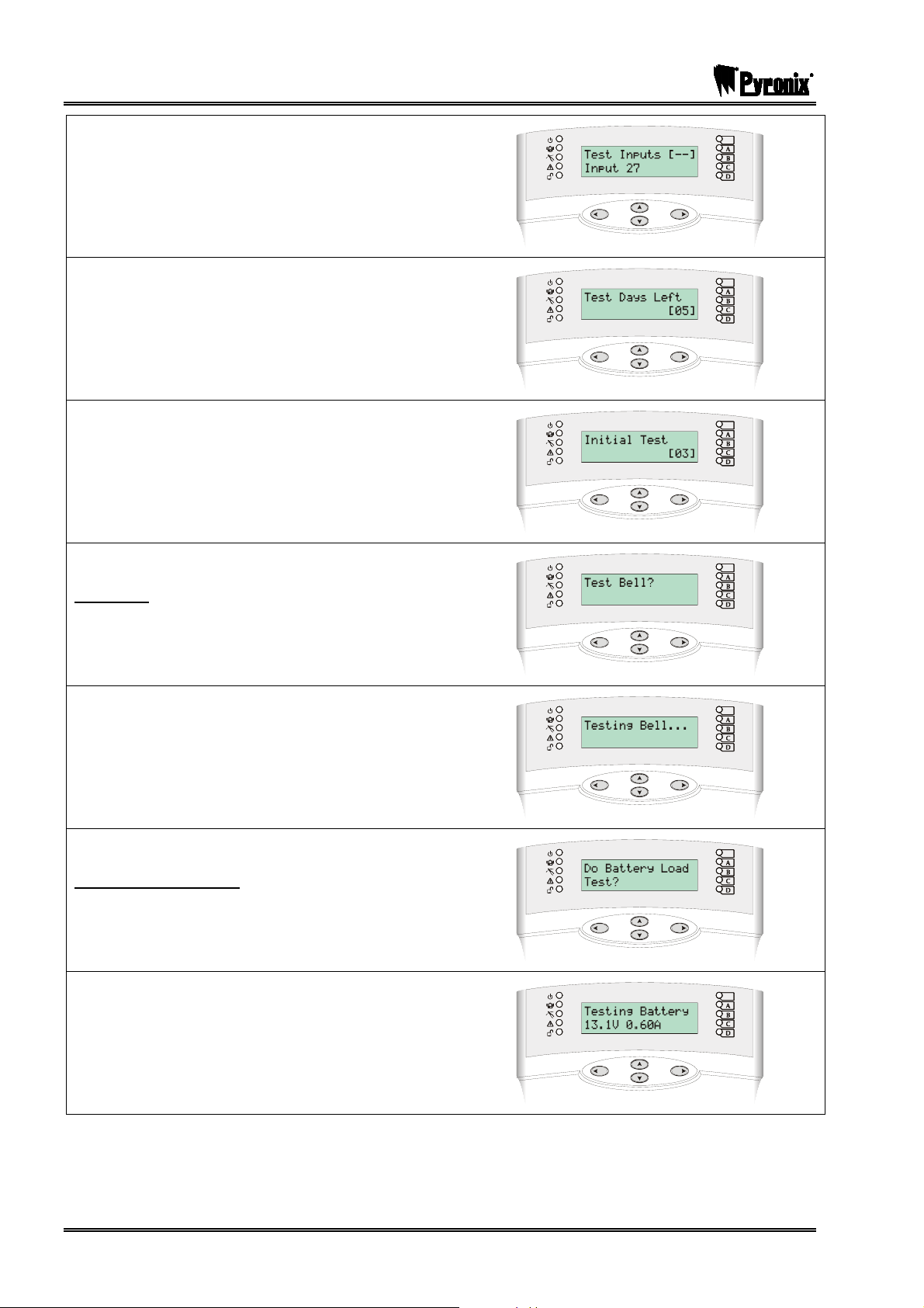
PCX SMS AND PCX 256 SYSTEM MANUAL
Enter the number of the inputs you wish to soak test
and press O. The input number shows on the
scrolling list. Repeat for each input to be tested. To
remove an input from the list, enter its number again.
Press the P key.
Enter the number of days the soak test will last. Press
the Okey.
Enter the number of days the soak test will revert to in
the event a soak input is triggered during testing.
Press the Okey. ‘Test Control’ will be displayed,
press the P key.
Test Bell?
To Test the Bell press the Okey.
All outputs programmed as either Bell or Strobe will
be tested. Press the P key to stop the test. ‘Test
Bell’ will be displayed, press the P key.
Do Battery Load Test?
To perform a Battery Load Test, press the Okey.
The Battery Load test will be started.
Page: 90 RINS871-3
Page 91

PCX SMS AND PCX 256 SYSTEM MANUAL
Once the Battery test has completed, press the O
key, ‘Do Battery Load Test’ will be displayed, press
the Pkey.
Test PGMs?
To test the PGMs press the Okey.
Select the PGMs you would like to test (see page 75
for the PGM types) and press the Okey.
All outputs programmed as the type selected above
will be active. Press the Pkey. The outputs will
switch off. Repeat for other output types as required.
Press the Pkey. ‘Test PGM’s’ will be displayed.
Press the Pkey.
Test PHC Communications?
To test the PHC Communications press the Okey.
Press the Pkey if you are not using a PABX or
press the Okey if you are (i.e. if you need a “9” to
dial an outside line).
Please wait will be displayed
Press the Pkey once it has completed. ‘Test PHC
Communications’ will be displayed, press the Pkey.
You will be returned to the Engineer Menu.
If the test has failed please see page 143.
RINS871-3 Page: 91
Page 92

PCX SMS AND PCX 256 SYSTEM MANUAL
13.21 Diagnostics
The system diagnostics are available for all parts of the system, including any remote power supplies if fitted.
The diagnostic resolution is:
¾ Voltage: 0.1V
¾ Current: 0.01A
The diagnostics that can be viewed are:
System voltage and current at the control panel and at each individual power supply.
System voltage at each keypad / tag reader.
Battery condition and charge current at control panel or any remote power supply.
Display inputs – current state of all inputs connected to a single system component, displayed in real time.
Calibration – permits calibration if control panel PSU voltage, using a calibrated meter.
Visual Keypad Programming Procedure
DIAGNOSTICS
Diagnostics
Using the mand Pkeys, scroll to ‘DIAGNOSTICS’
Press the Okey
To view the diagnostics of the power supplies press
the Okey
The Endstation PSU statistics will be displayed. Press
the Okey.
Enter the address of the RIX you wish to view.
Repeat for each RIX. Press the Okey.
Page: 92 RINS871-3
Page 93

PCX SMS AND PCX 256 SYSTEM MANUAL
Enter the address of the ROX you wish to view.
Repeat for each ROX. Press the Okey.
Enter the address of the Keypad you wish to view.
Repeat for each Keypad. Press the Okey.
Enter the address of the Reader you wish to view.
Repeat for each Reader. Press the Okey. ‘View
PSUs’ will be displayed, press the Pkey.
To view the input diagnostics, press the Okey.
To view the Endstation inputs only, press the Okey.
The status of the inputs will be shown.
C = Closed. O = Open. F = Fault
Press the Okey.
The circuit resistance will be shown on any on the
inputs you choose (enter the input number).
Press the Pkey.
RINS871-3 Page: 93
Page 94

PCX SMS AND PCX 256 SYSTEM MANUAL
Enter a RIX address and repeat the above for the RIX
inputs. Press the Pkey. Repeat for the keypad and
reader inputs. Press the Pkey. ‘View Inputs’ will be
displayed, press the Pkey.
If you would like to calibrate the PSU voltage of the
PCX system, Press the Okey and enter
#.
Place a calibrated volt meter across the battery
connectors (with the battery disconnected) or across
the auxiliary terminals and use the ^and`until
you reach the desired voltage (13.7V is the
recommended value). Press the Okey. You will be
returned to the Engineer Menu.
13.22 Set Up Downloading
The PCX system has uploading and downloading capability. The PCX UDL Software allows you to monitor
the status of each input, alter programming, and review the logs.
There are two way that the panel communicates with the PC, one is remotely; via the telephone line (thus
you will require the digi modem card (PCX-DIGI+ARM) and the other is directly; by using an RS232 lead
(PCX-RS232L) which connects into the PCX 256 expander card and your PC.
13.22.1 Download By
Select either RS232 (direct connection) or Modem (remote dial in connection).
13.22.2 Security Mode
This function allows you to choose a range of dialling modes that can be used:
Auto Answer: permits the PC to dial into the panel.
Dial Back: permits the PC to dial the panel, which hangs up the call and dials the PC back to establish
communication.
Panel Dials: does not allow the PC to dial into the panel at all.
All modes allows the panel to dial the PC without restriction. At any time, the panel can be forced to dial the
PC by entering the Manager menu and selecting the Dial Out Menu. Please see page 109.
13.22.3 Telephone Line
Dedication Line: When the PC dials the panel, it will respond immediately.
Shared Line: When the PC dials the panel, it will hang up after the second ring, and dial again. The first call
primes the panel, which will then answer the second call.
13.22.4 ARM / Modem Telephone Number
To be used in conjunction with the ‘DIAL OUT MENU’ function (see page: 109), these are programmed for
the appropriate PC. The ARM telephone number is used in order for the panel to dial to a PC that shows all
activations (Not available on the PCX 26/SMS). The Modem telephone number is used to dial to a PC in
order to get all the data back.
Page: 94 RINS871-3
Page 95

PCX SMS AND PCX 256 SYSTEM MANUAL
Visual Keypad Programming Procedure
SET UP DOWNLOADING
Set Up Downloading
Using the mand Pkeys, scroll to ‘SET UP
DOWNLOADING’. Press the Okey
Download By
Enter : for Modem
Enter : for RS232
Press the Okey.
Security Mode
Enter : for Auto Answer
Enter : for Panel Dials
Enter #: for Dial Back
Press the Okey.
Telephone Line
Enter : for Dedicated
Enter : for Shared
Press the Okey.
Number of Rings To Prime
Only available if ‘Modem’ has been selected.
Enter the number of rings needed to prime the panel
to answer the next call (1-15). Press the Okey.
Modem Speed
DO NOT ALTER THIS SETTING UNLESS
INSTRUCTED BY CUSTOMER SUPPORT
RINS871-3 Page: 95
Page 96

PCX SMS AND PCX 256 SYSTEM MANUAL
Enter the Arm telephone number. Press the Okey.
This is not available on PCX 26/SMS.
Program PCs
Select the PC that will be used for programming.
Enter the telephone number of the PC that the panel
will communicate with.
Signal Alarms
Enter : for No
Enter : for Yes
Press the Okey.
Repeat for Signal Faults, Signal Open/Close and
Signal Access C. Press the Okey. ‘Program PCs’
will be displayed. Repeat for further PCs or press the
Pkey.
If required, enter a text password (see page 42).
Press the Okey.
Select the number of redials which the panel will
attempt (0-15). Press the Okey.
Select the time that the panel will wait for a reply (0-
99). Press the Okey.
Page: 96 RINS871-3
Page 97

PCX SMS AND PCX 256 SYSTEM MANUAL
Stop on Success
Enter : for No
Enter : for Yes
Press the Okey.
Dial Mode
Enter : for Retry Same
Enter : for Try Next
Press the Okey. You will be returned to the
Engineer Menu.
13.23 Programme DIGI / SMS?
The PCX system can be used to dial to an Alarm Receiving Centre or send SMS texts to a mobile phone.
The descriptions below are split into three sections – how to program Fast Format, Contact ID and SMS.
13.23.1 Programming Fast Format
The Fast Format type 4.8.1 is commonly used for BSIA Fast Format.
Up to four numbers can be programmed, each with individual account numbers, channel information and
back up telephone number option.
The channels can be individually programmed in the “Program Digi Channels” section. Each channel uses a
programmable output number. The default values are described on the next page.
Channel Default Type (PCX 26/SMS) Default Type (PCX 256)
1 Fire (PGM 0001) Fire (PGM 0001)
2 HU Device Any (PGM 0009) HU Device Any (PGM 0009)
3 Unconfirmed Any (PGM 0018) Unconfirmed Any (PGM 0018)
4 Final Arm Any (PGM 0022) Final Arm Any (PGM 0022)
5 Tamper Any (PGM 0007) Tamper Any (PGM 0007)
6 Confirmed Any (PGM 0006) Confirmed Any (PGM 0006)
7 Omit Rearm Any (0017) Omit Rearm Any (0017)
8 AC Fail (0052) AC Fail (0052)
9 Global Fault 1 (0055) Global Fault 2 (0056)
10 Test ATS (0064) Test ATS (0064)
Visual Keypad Programming Procedure
PROGRAMME DIGI/SMS
Fast Format
Programme Digi / SMS
Using the mand Pkeys, scroll to ‘PROGRAMME
DIGI/SMS’ Press the Okey
RINS871-3 Page: 97
Page 98

PCX SMS AND PCX 256 SYSTEM MANUAL
To program in an ARC number, press the Okey
Disable Digi/SMS
Enter : for No (Enables the Digi Modem)
Enter : for Yes
Press the Okey
Use the numeric keys to select the ARC details to
program. Press the Okey
Active
Enter : for No
Enter : for Yes (Enables the ARC Details)
Press the Okey
Choose Format
Select the Format you wish to use. The most common
protocol that is used in the UK is ‘Fast Format 4.8.1,
so select ‘0’. Use the pkey to scroll through the
different formats. Press the Okey
Enter the 1st telephone number.
Press the Okey.
Enter the 2nd telephone number.
Press the Okey.
Page: 98 RINS871-3
Page 99

PCX SMS AND PCX 256 SYSTEM MANUAL
Stop on Success
Enter : for No
Enter : for Yes
Press the Okey
ARC Account
Use the numeric keys to program the account number
of the central station (this will be given to you by your
ARC). Press the Okey.
Select the DIGI channels you require to be sent to the
ARC. Please see the table on page 97 for the default
channels.
Press the Okey.
Repeat for the restores you require to be sent to the
ARC.
Press the Okey.
Select the number of redials you require (0-15). Press
the Okey.
Select the time that the panel will wait for a reply (0-
99). Press the Okey.
Low Battery Report
Enter : for No
Enter : for Yes
Press the Okey
RINS871-3 Page: 99
Page 100

PCX SMS AND PCX 256 SYSTEM MANUAL
Test Calls
Enter : for No
Enter : for Timed
(If Timed is chosen you will need to enter the hours
and minutes once you have pressed the Okey)
Press the Okey
ARC Details will be displayed. Repeat the above for
any other ARC stations you are using. Press the
Pkey. ‘Program Digi/SMS Calls?’ will be displayed,
press the Pkey.
Program Digi Channels
Press the Okey to check that the Digi Channels are
what the ARC are looking for.
The first Digi Channel will be shown, once you have
checked this is correct, press the Okey to move to
the next.
To change this channel please see page 75 for the
output types. All default values are shown on page 97
Once you have completed all the Digi Channels,
‘Program Digi Channels will be displayed’.
Press the Pkey.
‘Program SMS Details’ will be displayed and Press
the Pkey.
3 Way Calling
Enter : for No
Enter : for Yes
Press the Okey. You will be returned to the
Engineer Menu.
Page: 100 RINS871-3
 Loading...