

Page 1
Operating Instructions
T82
Dual-Input Temperature Head Transmitter
BA01139O/09/EN/13.10
71207043
Valid as of version
01.00 (device version)
Page 2

Brief overview
For quick and straightforward commissioning:
T82
Safety instructions
t
Installation instructions
t
Wiring
t
Display and operating elements
t
Commissioning
Commissioning using the HART®-protocol interface - quick start for device configuration
for standard operation
Customer-specific configuration
Complex measurement tasks require additional functions to be configured that the user can
individually select, set and adapt to his process conditions by setting the appropriate
parameters. A detailed description of all the functions and device parameters.
(® ä 6)
(® ä 8)
(® ä 13)
(® ä 17)
(® ä 25)
(® ä 41)
2
Page 3

T82
Table of contents
Table of contents
1 Important document information ..... 4
1.1 About this document ..................... 4
1.2 Document conventions .................... 4
2 Basic safety instructions .............. 6
2.1 Requirements for the personnel .............. 6
2.2 Designated use .......................... 6
2.3 Operational safety ........................ 6
3 Identification ....................... 7
3.1 Nameplate ............................. 7
3.2 Scope of delivery ........................ 7
3.3 Certificates and approvals .................. 7
4 Installation instructions .............. 8
4.1 Incoming acceptance, transport, storage ......... 8
4.2 Installation conditions ..................... 8
4.3 Installation instructions .................... 8
4.4 Post-installation check .................... 12
5 Wiring ............................ 13
5.1 Quick wiring guide ...................... 13
5.2 Connecting the sensor cables ............... 14
5.3 Connecting the power supply and signal cables .. 14
5.4 Shielding and grounding .................. 15
5.5 Post-connection check ................... 16
11 Diagnostics and troubleshooting
11.1 Troubleshooting ........................ 27
11.2 Diagnostics events ...................... 29
11.3 Spare parts ............................ 32
11.4 Return .............................. 32
11.5 Disposal ............................. 32
11.6 Software history and overview of compatibility ... 32
..... 27
12 Technical data ..................... 33
13 Operating menu and parameter
description ........................ 41
13.1 "Display/operation" menu ................. 47
13.2 "Setup" menu .......................... 51
13.3 "Diagnostics" menu ...................... 62
13.4 "Expert" menu ......................... 70
Index .................................. 86
6 Operating options .................. 17
6.1 Overview of operation options .............. 17
6.2 Structure and function of the operating menu .... 18
6.3 Measured value display and operating elements .. 20
6.4 Access to the operating menu via the operating
tool ................................ 21
7 Integrating the transmitter via the
HART® protocol ................... 23
7.1 HART device variables and measured values ..... 23
7.2 Device variables and measured values ......... 23
8 Commissioning .................... 25
8.1 Function check ........................ 25
8.2 Switching on the transmitter ............... 25
8.3 Enabling configuration .................... 25
9 Maintenance ...................... 25
10 Accessories ........................ 26
3
Page 4
Important document information T82
DANGER
CAUTION
NOTICE
)
*
1 Important document information
1.1 About this document
1.1.1 Document function
These Operating Instructions contain all the information that is required in various phases of the
life cycle of the device: from product identification, incoming acceptance and storage, to
mounting, connection, operation and commissioning through to troubleshooting, maintenance
and disposal.
1.1.2 Safety Instructions
When using in hazardous areas, the national safety requirements must be met. Separate Ex
documentation is contained in these Operating Instructions for measurement systems that are to
mounted in hazardous areas. Strict compliance with the installation instructions, ratings and
safety instructions as listed in this supplementary documentation is mandatory. Ensure you are
using the correct Ex documentation for the relevant Ex-approved device.
1.2 Document conventions
1.2.1 Safety symbols
Symbol
A0011189-EN
A0011191-EN
A0011192-EN
1.2.2 Electrical symbols
Symbol
Meaning
Direct current
A terminal to which DC voltage is applied or through which direct current flows.
A0011197
Alternating current
A0011198
A terminal to which alternating voltage (sine-wave) is applied or through which alternating current flows.
Ground connection
A grounded terminal which, as far as the operator is concerned, is grounded via a grounding system.
A0011200
Protective ground connection
A terminal which must be connected to ground prior to establishing any other connections.
A0011199
Equipotential connection
A connection that has to be connected to the plant grounding system: This may be a potential
A0011201
equalization line or a star grounding system depending on national or company codes of practice.
Meaning
DANGER!
This symbol alerts you to a dangerous situation. Failure to avoid this situation will result
in serious or fatal injury.
CAUTION!
This symbol alerts you to a dangerous situation. Failure to avoid this situation can result
in minor or medium injury.
NOTE!
This symbol contains information on procedures and other facts which do not result in
personal injury.
4
Page 5
T82 Important document information
-
.
1.2.3 Symbols and notation for certain types of information
Symbol Meaning
Allowed
Indicates procedures, processes or actions that are allowed.
A0011182
Preferred
Indicates procedures, processes or actions that are preferred.
A0011183
Forbidden
Indicates procedures, processes or actions that are forbidden.
A0011184
Tip
Indicates additional information.
A0011193
Reference to documentation
Refers to the corresponding device documentation.
A0011194
Reference to page
Refers to the corresponding page number.
A0011195
Reference to graphic
Refers to the corresponding graphic number and page number.
A0011196
1., 2., 3. Series of steps
Result of a sequence of actions
Ã
1.2.4 Symbols and notation in graphics
Symbol
1,2,3 ...
A, B, C, ...
A-A, B-B, C-C, ...
Meaning
Item numbers
Views
Sections
Hazardous area
Indicates a hazardous area.
A0011187
Safe area (non-hazardous area)
Indicates a non-hazardous area.
A0011188
5
Page 6

Basic safety instructions T82
2 Basic safety instructions
2.1 Requirements for the personnel
The personnel for installation, commissioning, diagnostics and maintenance must fulfill the
following requirements:
►
Trained, qualified specialists must have a relevant qualification for this specific function and
task
►
Are authorized by the plant owner/operator
►
Are familiar with federal/national regulations
►
Before beginning work, the specialist staff must have read and understood the instructions in
the Operating Instructions and supplementary documentation as well as in the certificates
(depending on the application)
►
Following instructions and basic conditions
The operating personnel must fulfill the following requirements:
►
Being instructed and authorized according to the requirements of the task by the facility's
owner-operator
►
Following the instructions in these Operating Instructions
2.2 Designated use
The device is a universal and user-configurable temperature head transmitter with either one or
two sensor inputs for a resistance thermometer (RTD), thermcouples (TC) or resistance and
voltage transmitters. The device is designed for mounting in a flat-face terminal head as per DIN
43729. Installation on a DIN rail with the optional available DIN rail clip is also possible.
The manufacturer is not liable for damage caused by improper or non-designated use.
2.3 Operational safety
►
Operate the device in proper technical condition and fail-safe condition only.
►
The operator is responsible for interference-free operation of the device.
Hazardous area
To eliminate a danger for persons or for the facility when the device is used in the hazardous area
(e.g. explosion protection):
►
Based on the technical data on the nameplate, check whether the ordered device is permitted
for the intended use in the hazardous area. The nameplate can be found on the side of the
transmitter housing.
►
Observe the specifications in the separate supplementary documentation that is an integral
part of these Instructions.
Electromagnetic compatibility
The measuring system complies with the general safety requirements in accordance with EN
61010, the EMC requirements of IEC/EN 61326 and NAMUR Recommendation NE 21 and NE
89.
NOTICE
►
The unit must only be powered by a power supply that operates using an IEC 61010-1
compliant energy limited circuit, "SELV or Class 2 circuit".
6
Page 7
T82 Identification
1
11-30V / 23mA
OTMT82-xxxxx
HW 01.00.00-(1)
Temperature Transmitter
S/N 5B00240426C
FW 01.00.00-(1)
Made in Germany
Ta= -50…+85°C
2 3
4
5
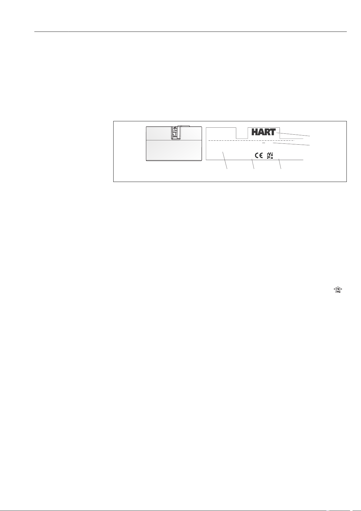
3 Identification
3.1 Nameplate
The right device?
Compare and check the data on the nameplate of the device against the requirements of the
measuring point:
A0016153
å 1
1
2 Serial number
3 Device revision
4 Power supply and current consumption
5 Device designation and communication symbol
Nameplate of the head transmitter (example, Ex version)
Approvals with symbols, if available (as option)
3.2 Scope of delivery
The scope of delivery of the device comprises:
• Temperature Head Transmitter
• Securing material
• Operating Instructions
•
Additional documentation for devices which are suitable for use in the hazardous area (0
1).
3.3 Certificates and approvals
The device left the factory in a safe operating condition. The device complies with the standards
EN 61 010-1 "Protection Measures for Electrical Equipment for Measurement, Control,
Regulation and Laboratory Procedures" and with the EMC requirements of IEC/EN 61326.
3.3.1 CE mark, declaration of conformity
The device therefore meets the legal requirements of the EC guidelines. The manufacturer
confirms a positive completion of all tests by fitting the unit with a CE mark.
3.3.2
The temperature transmitter is registered by HART® Communication. The device meets the
requirements of the HART Communication Protocol Specifications, April 2001, Revision 6.0.
HART® protocol certification
7
Page 8

Installation instructions T82
4 Installation instructions
4.1 Incoming acceptance, transport, storage
4.1.1 Incoming acceptance
• Is the packaging or content damaged?
• Is the delivery complete and is anything missing? Check the scope of delivery against your
order.
4.1.2 Transport and storage
• Pack the device in such a way as to protect it reliably against impact for storage (and
transportation). The original packaging provides optimum protection.
• The permitted storage temperature is -40 to +100 °C (-40 to 212 °F).
4.2 Installation conditions
4.2.1 Dimensions
The dimensions of the device are provided in the 'Technical data' section (® ä 33).
4.2.2 Installation point
• In the terminal head, flat face, as per DIN 43729, direct mounting on insert with cable entry
(middle hole 7 mm)
• In the field housing, separated from the process
It is also possible to mount the device on a top-hat rail as per EN 60715 using the DIN rail
clip accessory .
Information about the conditions (such as the ambient temperature, degree of protection, climate
class etc.) that must be present at the measuring point so that the device can be mounted
correctly is provided in the 'Technical data' section (® ä 33).
When using in the hazardous area, the limit values of the certificates and approvals must be
observed (see Ex-Safety Instructions).
4.3 Installation instructions
A Phillips head screwdriver is required to mount the head transmitter.
NOTICE
Do not overtighten the mounting screws as this could damage the head transmitter.
►
Maximum torque = 1 Nm (¾ pound-feet).
8
Page 9
T82 Installation instructions
1
2
3
4
5
6
7
9
8
1 2 3 4 5
1
2
3
4
A
B
C
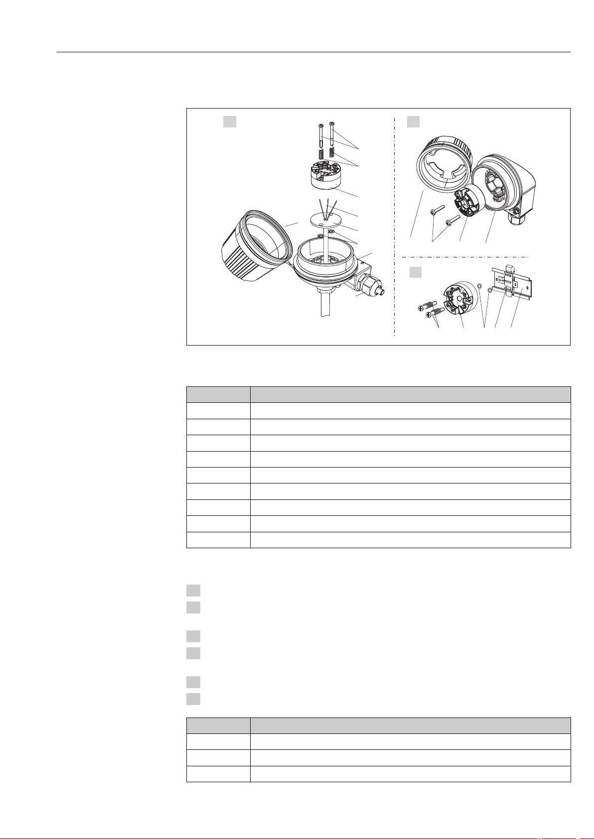
4.3.1 Mounting
A0019563
å 2
Head transmitter mounting (three versions)
Item A
1 Terminal head
2 Circlips
3 Insert
4 Connection wires
5 Head transmitter
6 Mounting springs
7 Mounting screws
8 Terminal head cover
9 Cable entry
Mounting in a terminal head (terminal head flat face as per DIN 43729)
Procedure mounting in a terminal head, item A:
1. Open the terminal head cover (8).
2. Guide the connection wires (4) of the insert (3) through the center hole in the head
transmitter (5).
3. Fit the mounting springs (6) on the mounting screws (7).
4. Guide the mounting screws (7) through the side boreholes of the head transmitter and the
insert (3). Then fix both mounting screws with the snap rings (2).
5. Then tighten the head transmitter (5) along with the insert (3) in the terminal head.
6.
After wiring, (® ä 13) close the terminal head cover (8) back on tight.
Item B
1 Field housing cover
2 Mounting screws with springs
3 Head transmitter
Mounting in a field housing
9
Page 10
Installation instructions T82
1
2 3 4 5
6
5
6
Item B Mounting in a field housing
4 Circlips
5 Field housing
Procedure mounting in a field housing, item B:
1. Open the cover (1) of the field housing (5).
2. Fit the mounting springs on the mounting screws (2) and guide the screws through the side
boreholes of the head transmitter (3). Then fix both mounting screws with the snap rings
(4).
3. Screw the head transmitter to the field housing.
4.
After wiring, (® ä 13) screw the field housing cover (1) back on.
Item C Mounting on top-hat rail (top-hat rail as per IEC 60715)
1 Mounting screws with springs
2 Head transmitter
3 Circlips
4 DIN rail clip
5 DIN rail
Procedure mounting on top-hat rail, item C:
1. Press the DIN rail clip (4) onto the top-hat rail (5) until it engages with a click.
2. Fit the mounting springs on the mounting screws (1) and guide the screws through the side
boreholes of the head transmitter (2). Then fix both mounting screws with the snap rings
(3).
3. Screw the head transmitter (2) onto the DIN rail clip (4).
4.3.2 Mounting typical of North America
10
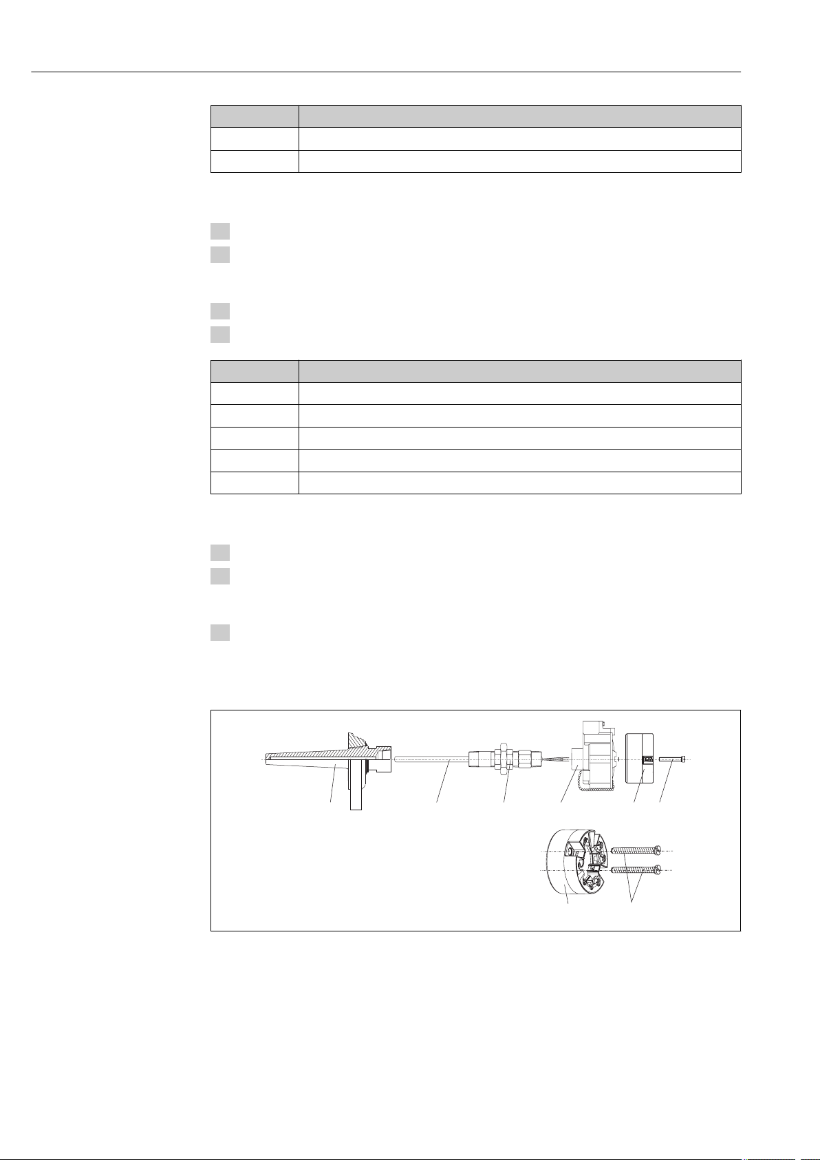
A0008520
å 3
1
2 Insert
3 Adapter, coupling
4 Terminal head
5 Head transmitter
6 Mounting screws
Head transmitter mounting
Thermowell
Page 11
T82 Installation instructions
Thermometer design with thermocouples or RTD sensors and head transmitter:
1. Fit the thermowell (1) on the process pipe or the container wall. Secure the thermowell
according to the instructions before the process pressure is applied.
2. Fit the necessary neck tube nipples and adapter (3) on the thermowell.
3. Make sure sealing rings are installed if such rings are needed for harsh environmental
conditions or special regulations.
4. Guide the mounting screws (6) through the lateral bores of the head transmitter (7).
5. Position the head transmitter (5) in the terminal head (4) in such a way that the bus cable
(terminals 1 and 2) point to the cable entry.
6. Using a screwdriver, screw down the head transmitter (5) in the terminal head (4).
7. Guide the connection wires of the insert (3) through the lower cable entry of the terminal
head (4) and through the middle hole in the head transmitter (5). Wire the connection wires
and transmitter with one another.
8. Screw the terminal head (4), with the integrated and wired head transmitter, onto the readymounted nipple and adapter (3).
NOTICE
The terminal head cover must be secured properly to meet the requirements for
explosion protection.
►
After wiring, securely screw the terminal head cover back on.
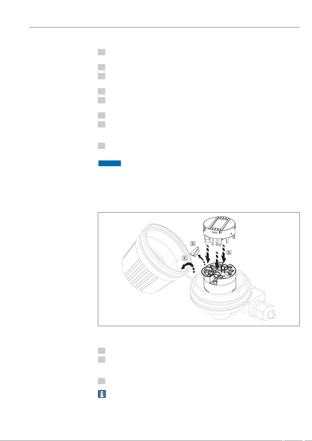
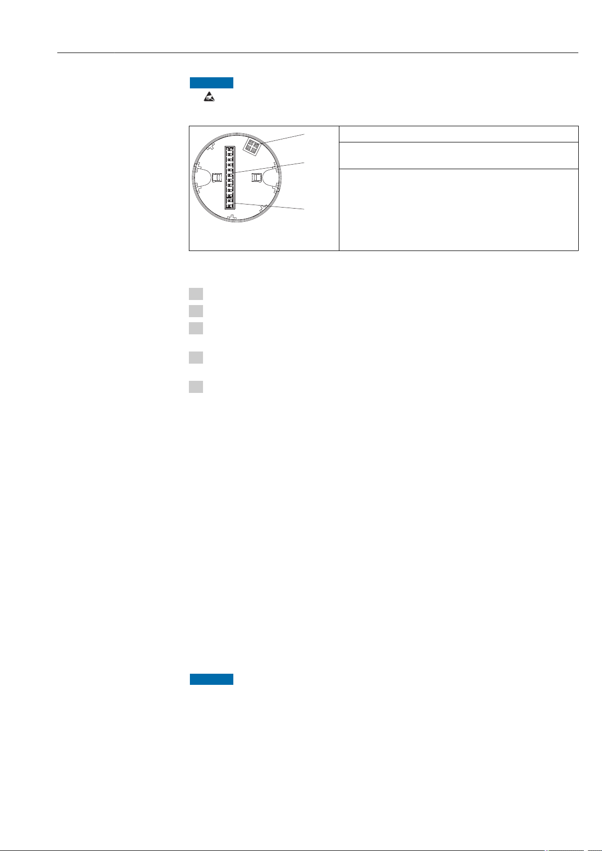
4.3.3 Mounting the display
å 4
Mounting the display
1. Loosen the screw on the terminal head cover. Flip back the terminal head cover (1).
2. Remove the cover of the display connection area (2). Fit the display module onto the
mounted and wired head transmitter. The fastening pins (3) must click securely into place
on the head transmitter.
3. After mounting, securely tighten the terminal head cover.
A0019561
The display can only be used with terminal head covers with a viewing window (e.g.
Endress+Hauser TA30).
11
Page 12

Installation instructions T82
4.4 Post-installation check
After installing the device, always run the following final checks:
Device condition and specifications Notes
Is the device undamaged (visual inspection)? -
Do the ambient conditions match the device specification (e.g. ambient temperature, measuring
range, etc.)?
See 'Technical data'
section (® ä 33)
12
Page 13
T82 Wiring
5 Wiring
CAUTION
!
►
Switch off power supply before installing or connecting the device. Failure to observe this may
result in destruction of parts of the electronics.
►
When installing Ex-approved devices in a hazardous area, please take special note of the
instructions and connection schematics in the respective Ex documentation added to these
Operating Instructions. The local supplier representative is available for assistance if required.
►
Do not occupy the display connection. An incorrect connection can destroy the electronics.
For wiring a mounted head transmitter, proceed as follows:
1. Open the cable gland and the housing cover on the terminal head or the field housing.
2. Feed the cables through the opening in the cable gland.
3.
Connect the cables as shown in (® ä 13). If the head transmitter is fitted with spring
terminals, pay particular attention to the information in the "Connecting to spring terminals"
section (® ä 14).
4. Retighten the cable gland and close the housing cover.
In order to avoid connection errors always take note of the hints given in the section connection
check!
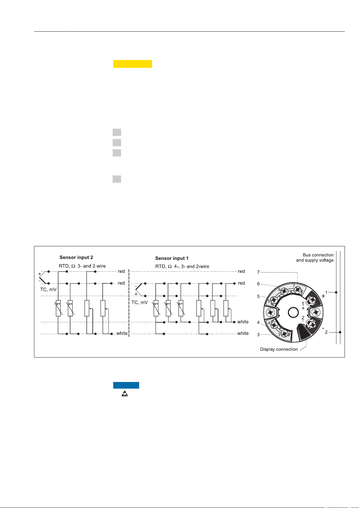
5.1 Quick wiring guide
Terminal assignment
å 5
►
Wiring the head transmitter
NOTICE
ESD - electrostatic discharge. Protect the terminals from electrostatic discharge. Failure to
observe this may result in destruction or malfunction of parts of the electronics.
A0007285-EN
13
Page 14
Wiring T82
5.2 Connecting the sensor cables
Terminal assignment of the sensor terminals (® å 5, ä 13).
NOTICE
When connecting 2 sensors, ensure that there is no galvanic connection between the
sensors (e.g. caused by sensor elements that are not isolated from the thermowell). The
resulting equalizing currents distort the measurement considerably.
►
The sensors must remain galvanically isolated from one another by connecting each sensor
separately to a transmitter. The transmitter provides sufficient galvanic isolation (> 2 kV AC)
between the input and output.
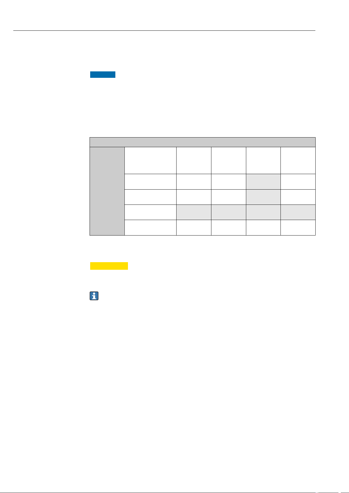
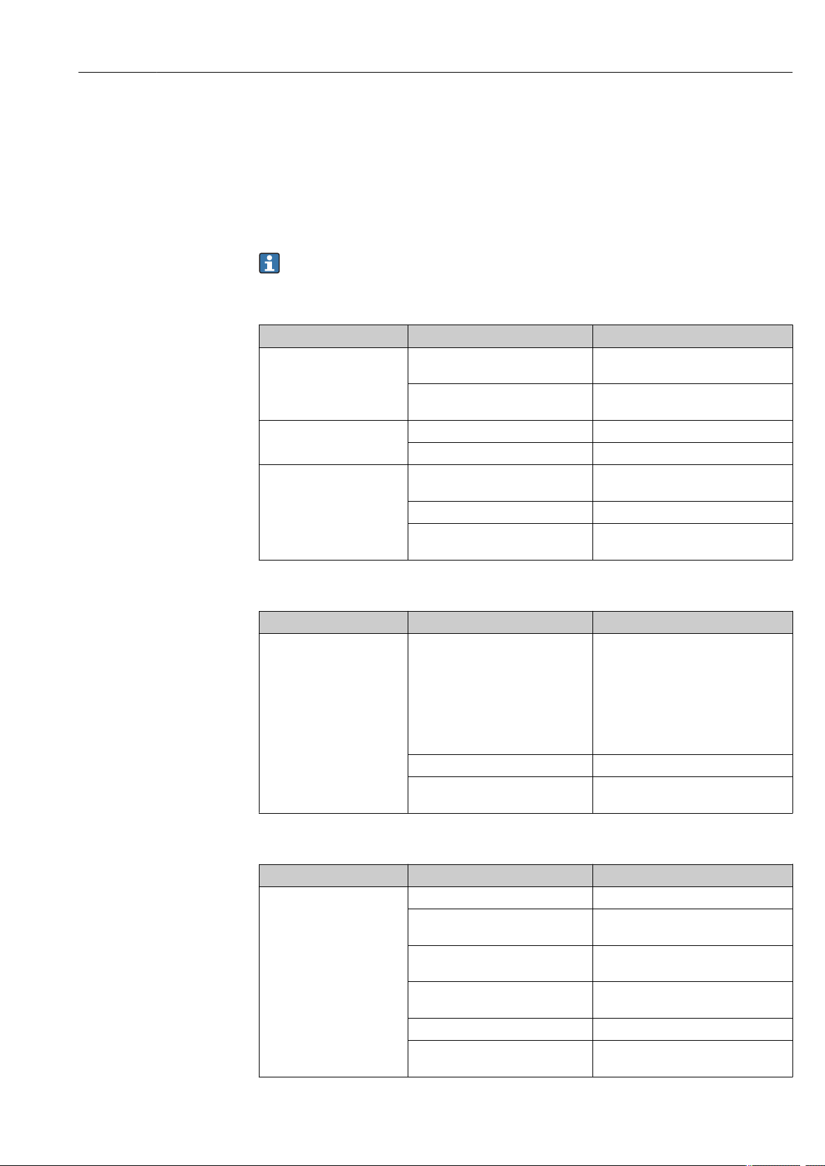
The following connection combinations are possible when both sensor inputs are assigned:
Sensor input 1
Sensor input 2
RTD or resistance
transmitter, two-wire
RTD or resistance
transmitter, three-wire
RTD or resistance
transmitter, four-wire
Thermocouple (TC),
voltage transmitter
RTD or
resistance
transmitter,
two-wire
4 4 - 4
4 4 - 4
- - - -
4 4 4 4
RTD or
resistance
transmitter,
three-wire
RTD or
resistance
transmitter,
four-wire
Thermocouple
(TC), voltage
transmitter
5.3 Connecting the power supply and signal cables
CAUTION
!
►
Switch off power supply before installing or connecting the head transmitter. Failure to
observe this may result in destruction of parts of the electronics.
Cable specification
• A normal device cable suffices if only the analog signal is used.
• A shielded cable is recommended for HART® communication. Take the plant grounding
concept into consideration.
Please also observe the general procedure on (® ä 13).
14
Page 15
T82 Wiring
*
*
1
2
3
4
2-
1+
21+
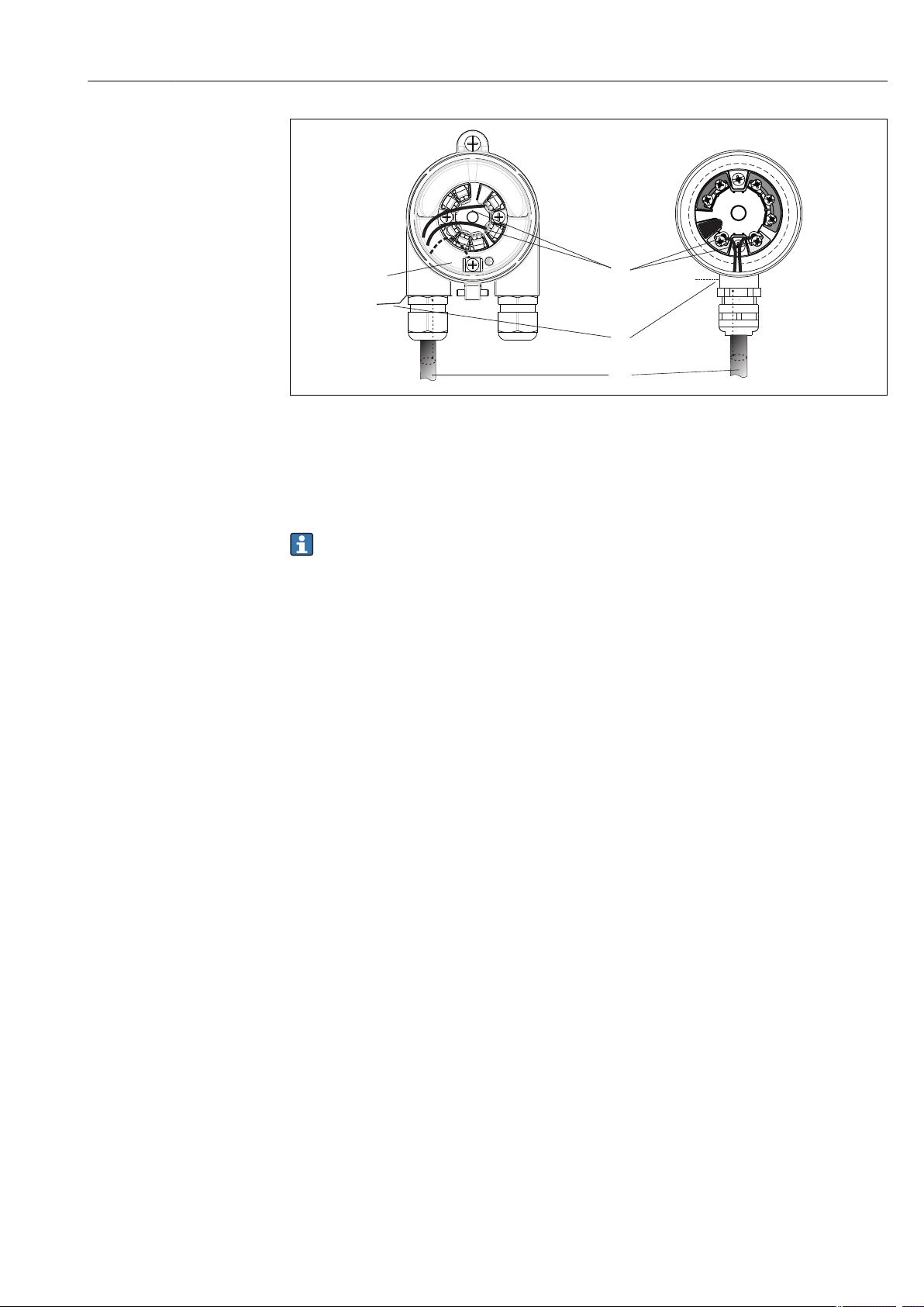
A0008284
å 6
A
B Internal ground terminal
C External ground terminal
D
Connecting the signal cable and power supply - left: installed in field housing, right: installed in terminal head
Terminals for HART® -protocol and power supply
Shielded signal cable (recommended for HART® protocol)
• The terminals for connecting the signal cable (1+ and 2-) are protected against reverse
polarity.
• Conductor cross-section:
– Max. 2.5 mm2 for screw terminals
– Max. 1.5 mm2 for spring terminals
5.4 Shielding and grounding
Optimum electromagnetic compatibility (EMC) can only be guaranteed if the system components
and, in particular, the lines are shielded and the shield forms as complete a cover as possible. A
shield coverage of 90% is ideal.
• To ensure an optimum EMC protective effect when communicating with HART®, connect the
shield as often as possible to the reference ground.
• For reasons of explosion protection, you should refrain from grounding however.
To comply with both requirements, three different types of shielding are possible when
communicating with HART®:
• Shielding at both ends
• Shielding at one end on the feed side with capacitance termination at the field device
• Shielding at one end on the feed side
Experience shows that the best results with regard to EMC are achieved in most cases in
installations with one-sided shielding on the feed side (without capacitance termination at the
field device). Appropriate measures with regard to input wiring must be taken to allow
unrestricted operation when EMC interference is present. These measures have been taken into
account for this device. Operation in the event of disturbance variables as per NAMUR NE21 is
thus guaranteed. Where applicable, national installation regulations and guidelines must be
observed during the installation! Where there are large differences in potential between the
individual grounding points, only one point of the shielding is connected directly with the
reference ground. In systems without potential equalization, therefore, cable shielding of fieldbus
systems should only be grounded on one side, for example at the supply unit or at safety barriers.
15
Page 16
Wiring T82
-
.
1
2
3
4
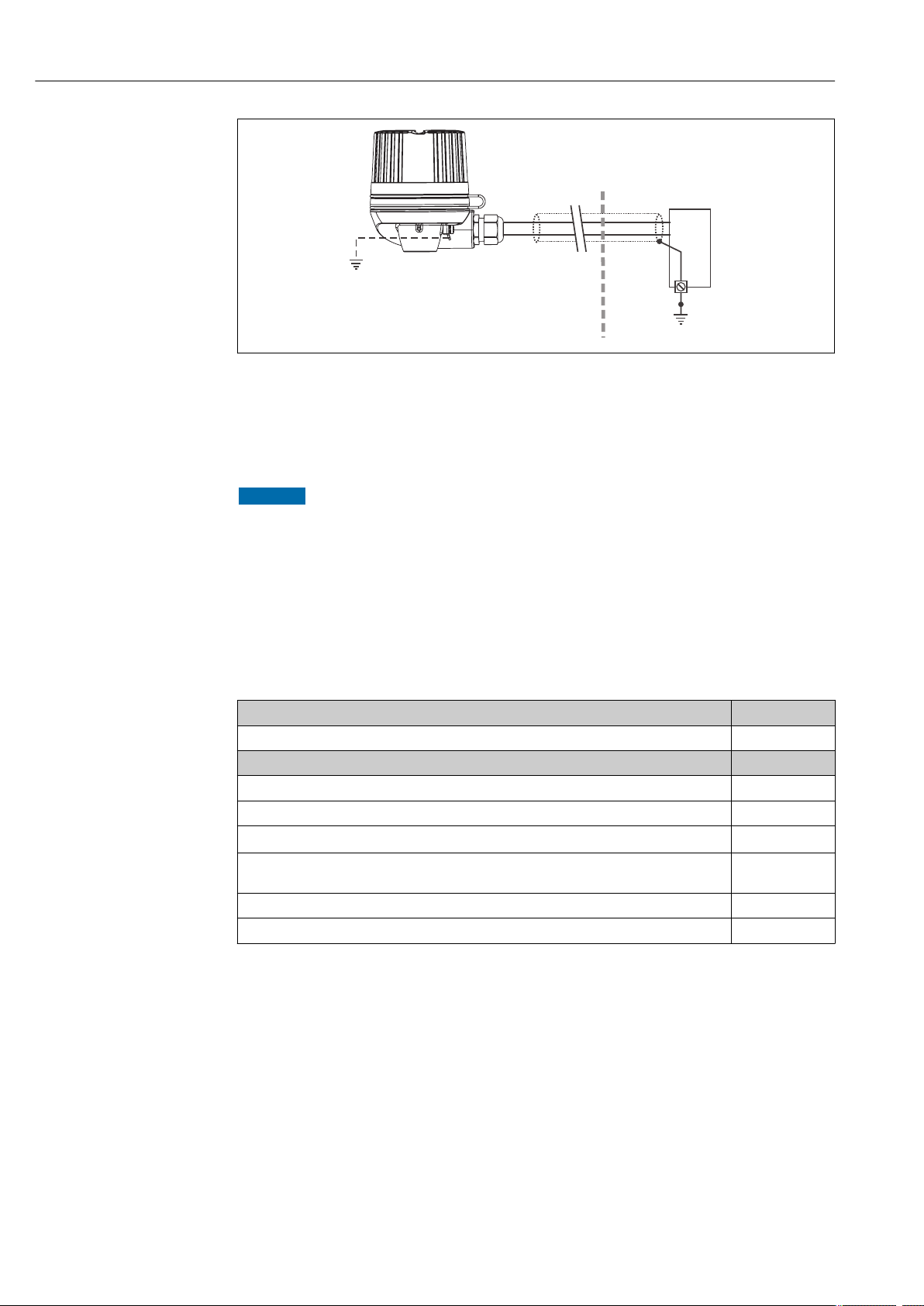
A0019556
å 7
1
2 Grounding of the cable shield at one end
3 Supply unit
4
Shielding and grounding the signal cable at one end with HART® communication
Optional grounding of the field device, isolated from cable shielding
Grounding point for HART® communication cable shield
NOTICE
If the shielding of the cable is grounded at more than one point in systems without
potential matching, power supply frequency equalizing currents can occur that damage
the signal cable or have a serious effect on signal transmission.
►
In such cases the shielding of the signal cable is to be grounded on only one side, i.e. it must
not be connected to the ground terminal of the housing (terminal head, field housing). The
shield that is not connected should be insulated!
5.5 Post-connection check
Device condition and specifications
Is the device or cable undamaged (visual inspection)? --
Electrical connection Notes
Does the supply voltage match the specifications on the nameplate? U = 11 to 42 V DC
Do the cables have adequate strain relief? --
Are the power supply and signal cables correctly connected?
Are all the screw terminals well tightened and have the connections of the spring terminals been
checked?
Are all the cable entries installed, tightened and sealed? --
Are all the housing covers installed and tightened? --
Notes
(® ä 13)
--
16
Page 17
T82 Operating options
1
2
4
5
7
6
3
ON
OFF
1
2
4
8
16
32
64
HW
SW
ADDR
SIM
WRITE LOCK
DISPL. 180°
8
6 Operating options
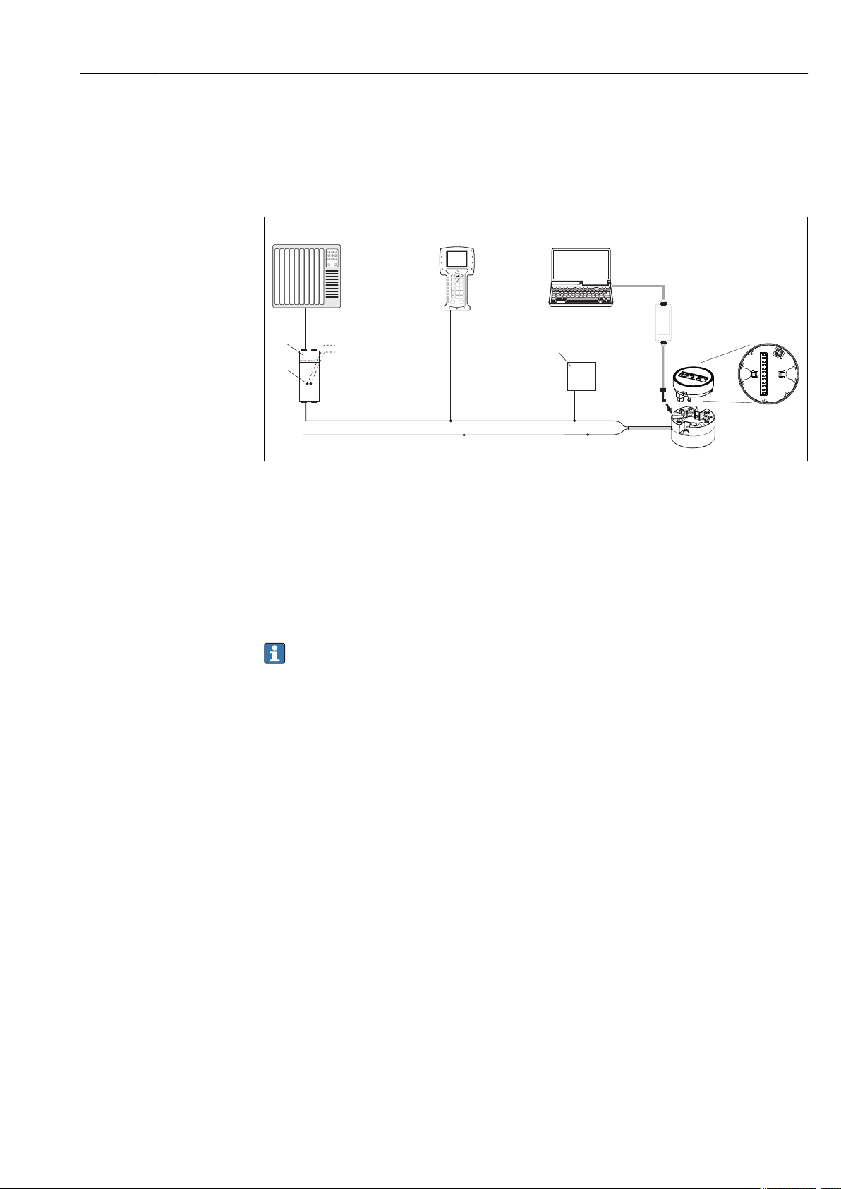
6.1 Overview of operation options
A0014460
å 8
1
2 Transmitter power supply unit (with communication resistor)
3
4 Field Communicator 375, 475
5 Computer with operating tool (e.g. FieldCare, AMS Device Manager, SIMATIC PDM)
6
7 Interface adapter FXA291 (E+H) for connecting to the CDI (Common Data Interface) interface
8 Local operation via DIP switches on the rear of the optional display
Operating options of the head transmitter
PLC (programmable logic controller)
Connection for HART® modems
HART® modem, e. g. FXA19x, RS232- or USB-connection (E+H)
Display and operating elements are only available locally if the head transmitter was ordered
with a display unit!
17
Page 18

Operating options T82
Expert
System
Sensor
Communication
Diagnostics
Operating menu for experts
Display/operat.
Display interval
Format display
Decimal places 1
Setup
Advanced setup
Device tag
Diagnostics
Operating menu for operators and maintenances
Value 1 display
Operator
Maintenance
Expert
Output
Unit
Sensor type
Lower range value
Upper range value
Enter access code
Locking status
Sensor Sensor offset
Current output
Output current
Actual diagnostics
Operating time
Diagnostics list Actual diagnostics count
Device reset Device reset
Enter access code
Unit
Mains filter
Display Display interval
Sensor Sensor type
Output current
Current trimming
HART config.
HART info
HART output
Burst mode
Device type
Assign PV
Actual diagnostics
Diagnostics list Actual diagnostics count
Event logbook
Device information
Simulation
Device reset
Previous diagnostics
Device tag
Min/max values
Sensor 1 min v.
Simulation current output
Device reset
Sensor value
Sensor value
6.2 Structure and function of the operating menu
6.2.1 Structure of the operating menu
18
A0014757-EN
Page 19

T82 Operating options
6.2.2 Submenus and user roles
Certain parts of the menu are assigned to certain user roles. Each user role corresponds to typical
tasks within the lifecycle of the device.
User role Typical tasks Menu Content/meaning
Operator Tasks during operation:
• Configuration of the display.
• Reading measured values.
Maintenance Commissioning:
• Configuration of the measurement.
• Configuration of data processing (scaling, linearization,
etc.).
• Configuration of the analog measured value output.
Fault elimination:
• Diagnosing and eliminating process errors.
• Interpretation of device error messages and correcting
associated errors.
Expert Tasks that require detailed knowledge of the function of
the device:
• Commissioning measurements under difficult
conditions.
• Optimal adaptation of the measurement to difficult
conditions.
• Detailed configuration of the communication interface.
• Error diagnostics in difficult cases.
"Display/operation" Contains all the parameters that are required in ongoing
"Setup" Contains all parameters for commissioning:.
"Diagnostics" Contains all parameters for detecting and analyzing errors:
"Expert" Contains all parameters of the device (including those that
operation: configuration of the measured value display
(displayed values, display format, etc.).
Setup parameters
•
Once values have been set for these parameters, the
measurement should generally be completely configured.
"Advanced setup" submenu
•
Contains additional submenus and parameters:
– For more accurate configuration of the measurement
(adaptation to special measuring conditions).
– For converting the measured value (scaling,
linearization).
– For scaling the output signal.
Diagnostic list
•
Contains up to 3 currently pending error messages.
Event logbook
•
Contains the 5 most recent error messages (no longer
pending).
"Device information" submenu
•
Contains information for identifying the device.
"Measured values" submenu
•
Contains all current measured values.
"Simulation" submenu
•
Is used to simulate measured values or output values.
"Device reset" submenu
•
are already in one of the other menus). This menu is
structured according to the function blocks of the device:
"System" submenu
•
Contains all higher-order device parameters that do not
pertain either to measurement or the measured value
communication.
"Sensors" submenu
•
Contains all parameters for configuring the
measurement.
"Output" submenu
•
Contains all parameters for configuring the analog
current output.
"Communication" submenu
•
Contains all parameters for configuring the digital
communication interface.
"Diagnostics" submenu
•
Contains all parameters for detecting and analyzing
errors.
19
Page 20
Operating options T82
1
2
3
4
5
6
7
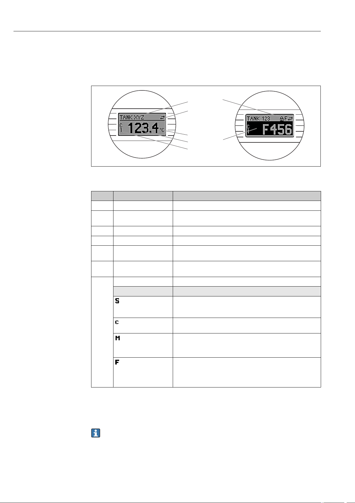
6.3 Measured value display and operating elements
6.3.1 Display
A0008549
å 9
Optional LC display of the head transmitter
Item No. Function Description
1 Displays the TAG TAG, 32 characters long.
2 'Communication' symbol The communication symbol appears when read and write-accessing via the
fieldbus protocol.
3 Unit display Unit display for the measured value displayed.
4 Measured value display Displays the current measured value.
5 Value/channel display S1,
S2, DT, PV, I, %
6 'Configuration locked'
symbol
7 Status signals
Symbols Meaning
e.g. S1 for a measured value from channel 1 or DT for the device
temperature
The 'configuration locked' symbol appears when configuration is locked via
the hardware.
"Out of specification"
The device is being operated outside its technical specifications (e.g. during
startup or a cleaning).
"Service mode"
The device is in service mode (e.g. during a simulation).
"Maintenance required"
Maintenance is required. The measured value is still valid.
The display alternates between the measured value and the status message.
"Operating error" error message
An operating error has occurred. The measured value is no longer valid.
The display alternates between the error message and "- - - -" (no valid
measured value present), see ’Diagnostic events’ section.
20
6.3.2 Local operation
You can make hardware settings for the fieldbus interface using miniature switches (DIP
switches) on the rear of the optional display.
The user has the option of ordering the display with the transmitter, or as an accessory for
subsequent mounting.
Page 21
T82 Operating options
ON
OFF
1
2
4
8
16
32
64
HW
SW
ADDR ACTIVE
SIM
WRITE LOCK
DISPL. 180°
1
2
3
NOTICE
►
ESD - electrostatic discharge. Protect the terminals from electrostatic discharge. Failure to
observe this may result in destruction or malfunction of parts of the electronics.
1: Connection to head transmitter
2: DIP switch (1 - 64, SW/HW, ADDR and SIM = simulation mode) no
function for this head transmitter
3: DIP switch (WRITE LOCK = write protection; DISPL. 180° = switch,
turn the display monitor 180°)
A0014562
å 10
Hardware settings via DIP switches
Procedure for setting the DIP switch:
1. Open the cover of the terminal head or field housing.
2. Remove the attached display from the head transmitter.
3. Configure the DIP switch on the rear of the display accordingly. In general: switch to ON =
function enabled, switch to OFF = function disabled.
4. Fit the display onto the head transmitter in the correct position. The head transmitter accepts
the settings within one second.
5. Secure the cover back onto the terminal head or field housing.
Switching write protection on/off
Write protection is switched on and off via a DIP switch on the rear of the optional attachable
display. When write protection is active, parameters cannot be modified. This is shown on the
display as a key symbol when a hardware lock is activated ("WRITE LOCK" to "ON").Write
protection prevents any write access to the parameters.
Turning the display
The display can be rotated 180° using the "DISPL. 180°" DIP switch. The setting is retained
when the display is removed.
6.4 Access to the operating menu via the operating tool
6.4.1 FieldCare
Function scope
FDT/DTM-based plant asset management tool from Endress+Hauser. Access takes place via the
HART® protocol or CDI (Common Data Interface) interface.
NOTICE
Before accessing the device via the CDI (Common Data Interface) interface to the
interface adapter FXA291, disconnect the transmitter from the power supply, terminals
(1+) and (2-).
►
Failure to comply with this instruction can result in damage to parts of the electronics.
Source for device description files
See data (® ä 23).
21
Page 22

Operating options T82
6.4.2 AMS Device Manager
Function scope
Program from Emerson Process Management for operating and configuring measuring devices via
the HART® protocol.
Source for device description files
See data (® ä 23).
6.4.3 SIMATIC PDM
Function scope
Program from Siemens for the operation, configuration, maintenance and diagnosis of intelligent
field devices via the HART® protocol.
Source for device description files
See data (® ä 23).
6.4.4 Field Communicator 375/475
Function scope
Industrial handheld terminal from Emerson Process Management for remote configuration and
measured value display via the HART® protocol.
Source for device description files
See data (® ä 23).
22
Page 23
T82
Integrating the transmitter via the HART® protocol
7
Integrating the transmitter via the HART
®
protocol
Version data for the device
Firmware Version 01.00.zz • On the title page of the Operating instructions
• On the nameplate
• Parameter firmware version
Diagnostics ® Device info® Firmware version
Manufacturer ID 00b5 Manufacturer ID parameter
Diagnostics ® Device info® Manufacturer ID
Device type ID 0081 Device type parameter
Diagnostics ® Device info ® Device type
HART protocol revision 6.0 ---
Device revision 1 • On the transmitter nameplate
• Device revision parameter
Diagnostics ® Device info ® Device revision
The following is a list of the suitable device description (DD) file for each individual operating tool
with information on the source.
Operating tools
Operating tool
FieldCare
(Endress+Hauser)
AMS Device Manager
(Emerson Process Management)
Field Communicator 375, 475
(Emerson Process Management)
Sources for obtaining device descriptions (DD)
www.endress.com ® Download Area
Internet-download on the manufacturer's website
Use update function of handheld terminal
7.1 HART device variables and measured values
The following measured values are assigned to the device variables at the factory:
Device variables for temperature measurement
Device variable
Primary device variable (PV) Sensor 1
Secondary device variable (SV) Device temperature
Tertiary device variable (TV) Sensor 1
Quaternary device variable (QV) Sensor 1
Measured value
It is possible to change the assignment of device variables to process variables in the Expert
® Communication ® HART output menu.
7.2 Device variables and measured values
The following measured values are assigned to the individual device variables:
Device variable code
0 Sensor 1
1 Sensor 2
Measured value
23
Page 24

Integrating the transmitter via the HART® protocol
Device variable code Measured value
2 Device temperature
3 Average of sensor 1 and sensor 2
4 Difference between sensor 1 and sensor 2
5 Sensor 1 (backup sensor 2)
6 Sensor 1 with switchover to sensor 2 if a limit value is exceeded
7 Average of sensor 1 and sensor 2 with backup
The device variables can be queried by a HART® master via HART® command 9 or 33.
T82
24
Page 25
T82 Commissioning
8 Commissioning
8.1 Function check
Before commissioning the measuring point make sure that all final checks have been carried out:
•
Checklist “Post-installation check”, (® ä 12)
•
Checklist “Post-connection check”, (® ä 13)
8.2 Switching on the transmitter
Once the final checks have been successfully completed, it is time to switch on the supply
voltage. The transmitter performs a number of internal test functions after power-up. As this
procedure progresses, the following sequence of messages appears on the display:
Step Display
1 "Display" text and firmware version of the display
2 Firm logo
3 Device name with firmware and hardware versions
4 Information on the sensor configuration (sensor element and type of connection)
5 Set measuring range
6a Current measured value or
6b Current status message
If the switch-on procedure is not successful, the relevant diagnostics event, depending on the cause, is
displayed. A detailed list of diagnostic events and the corresponding troubleshooting instructions can be
found in the "Diagnostics and troubleshooting" section (® ä 27).
The device is operational after approx. 8 seconds, and the plug-in display after approx. 12 seconds
in normal operating mode! Normal measuring mode commences as soon as the switch-on
procedure is completed. Measured values and status values appear on the display.
8.3 Enabling configuration
If the device is locked and the parameter settings cannot be changed, it must first be enabled via
the hardware lock. The device is locked using the hardware if the keyhole symbol appears in the
header of the measured value display. To unlock the device, switch the write protection switch
on the back of the display to the "OFF" position (® ä 21).
9 Maintenance
In general, no specific maintenance is required for this device.
25
Page 26

Accessories T82
10 Accessories
Various accessories, which can be ordered separately from your supplier, are available for the
device. Detailed information on the order code in question can be obtained from your service
organization. When ordering accessories, please specify the serial number of the device!
The following accessories are contained in the scope of delivery:
• Operating Instructions
• Supplementary documentation for use in hazardous areas
• Mounting material for head transmitter
Accessory
Display, pluggable
Field housing for head transmitter, aluminum, IP 66, dimensions B x H x T: 100 x 100 x 60 mm (3.94" x 3.94" x 2.36")
DIN rail clip according to IEC 60715 for head transmitter mounting
Standard - DIN mounting set (2 screws + springs, 4 securing disks and 1 display connector cover)
US - M4 mounting screws (2 screws M4 and 1 display connector cover)
26
Page 27
T82 Diagnostics and troubleshooting
11 Diagnostics and troubleshooting
11.1 Troubleshooting
Always start troubleshooting with the checklists below if faults occur after start up or during
operation. This takes you directly (via various queries) to the cause of the problem and the
appropriate remedial measures.
Due to the its design, the device cannot be repaired. However, it is possible to send the
device in for examination. See the information in the "Return" section (® ä 32).
General errors
Problem Possible cause Remedy
Device not reacting. Supply voltage does not match that
specified on the nameplate.
No contact between connecting cables
and terminals.
Output current < 3.6 mA Signal cable is wired incorrectly. Check wiring.
Electronics are defective. Replace the device.
HART communication not
working.
Missing or incorrectly installed
communication resistor.
HART-Modem is connected incorrectly. Connect HART-Modem correctly.
HART-Modem is not set to "HART". Set HART-Modem selector switch to
Apply the correct voltage.
Check the contacting of the cables and
correct if necessary.
Install the communication resistor (250 W)
correctly.
"HART".
Checking the display
Problem
No display visible
Possible cause Remedy
No supply voltage • Check the supply voltage at the head
transmitter → Terminals + and -.
• Ensure that the display module holders
are correctly seated and that the display
module is properly connected to the
head transmitter, (® ä 8).
• If possible test the display module with
another suitable head transmitter.
The display module is defective. Replace the module.
The electronics of the head transmitter
are defective.
Replace the head transmitter.
Application errors without status messages for RTD sensor connection
Problem
Measured value is incorrect/
inaccurate
Possible cause Remedy
Incorrect sensor orientation. Install the sensor correctly.
Heat conducted by sensor. Observe the face-to-face length of the
sensor.
Device programming is incorrect
(number of wires).
Device programming is incorrect
(scaling).
Incorrect RTD configured. Change the Sensor type device function.
Sensor connection. Check that the sensor is connected
Change the Connection type device
function.
Change scaling.
correctly.
27
Page 28

Diagnostics and troubleshooting T82
Problem Possible cause Remedy
Failure current (≤ 3.6 mA or
≥ 21 mA)
The cable resistance of the sensor (2wire) was not compensated.
Offset incorrectly set. Check offset.
Faulty sensor. Check the sensor.
RTD connected incorrectly. Connect the connecting cables correctly
Incorrect device programming (e.g.
number of wires).
Incorrect programming. Incorrect sensor type set in the Sensor
Compensate the cable resistance.
(terminal diagram).
Change the Connection type device
function.
type device function. Set the correct sensor
type.
Application errors without status messages for TC sensor connection
Problem Possible cause Remedy
Incorrect sensor orientation. Install the sensor correctly.
Heat conducted by sensor. Observe face-to-face length of the sensor.
Measured value is incorrect/
inaccurate
Failure current (≤ 3.6 mA or
≥ 21 mA)
Device programming is incorrect
(scaling).
Incorrect thermocouple type (TC)
configured.
Incorrect comparison measuring point
set.
Interference via the thermocouple wire
welded in the thermowell (interference
voltage coupling).
Offset incorrectly set. Check offset.
Faulty sensor. Check the sensor.
Sensor is connected incorrectly. Connect the connecting cables correctly
Incorrect programming. Incorrect sensor type set in the Sensor
Change scaling.
Change the Sensor type device function.
Set the correct reference junction
(® ä 52).
Use a sensor where the thermocouple wire
is not welded.
(terminal diagram).
type device function. Set the correct sensor
type.
28
Page 29

T82 Diagnostics and troubleshooting
1
2
1
3
A
B
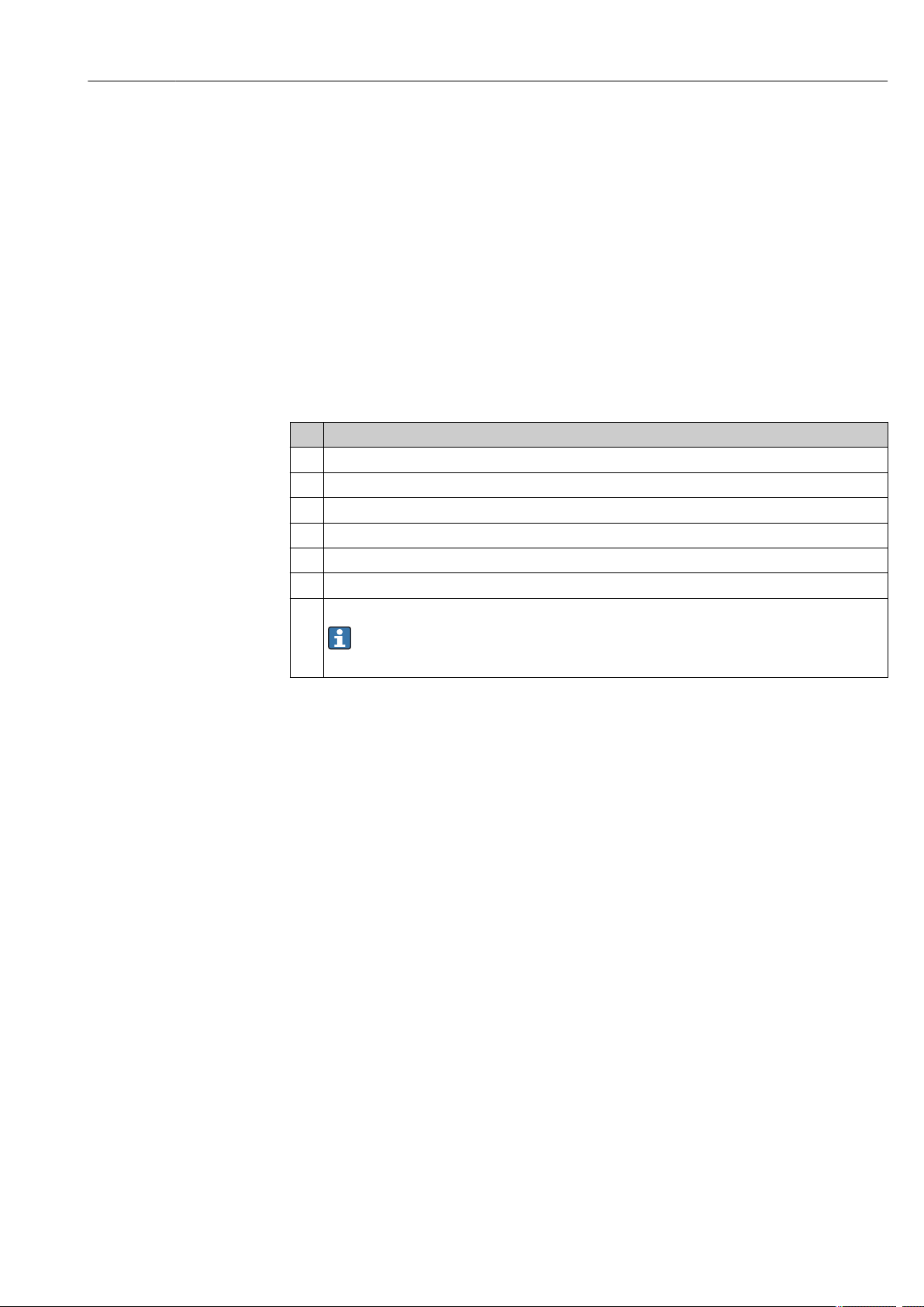
11.2 Diagnostics events
11.2.1 Displaying diagnostic events
A0014837
Display in the event of a warning
A
B Display in the event of an alarm
1 Status signal in the header
2 The display alternates between the primary measured value and the status - indicated by the appropriate letter (M,
C or S) - plus the defined error number.
3 The display alternates between "- - - -" (no valid measured value) and the status - indicated by the appropriate
letter (F) - plus the defined error number.
Status signals
Symbol
Event
category
Operating error An operating error has occurred. The measured value is no longer valid.
Maintenance
required
Service mode The device is in service mode (e.g. during a simulation).
Out of
specification
Meaning
Maintenance is required. The measured value is still valid.
The device is being operated outside its technical specifications (e.g. during startup or a
cleaning)
Diagnostic behavior
Alarm
Warning
The measurement is interrupted. The signal outputs take on the defined alarm condition.
A diagnostic message is generated (status signal F).
The device continues to measure. A diagnostic message is generated (status signals M, C
or S).
29
Page 30

Diagnostics and troubleshooting T82
Diagnostics event and event text
The fault can be identified using the diagnostics event. The event text helps you do so by
providing information about the fault.
Diagnostics event
Status signal Event number Event text
¯ ¯ ¯
Example
042 Sensor corroded
3-digit number
If two or more diagnostic messages are pending simultaneously, only the message with the
highest priority is shown. Additional pending diagnostic messages are shown in the Diagnostics
list submenu (® ä 63).
Past diagnostic messages that are no longer pending are shown in the Event logbook
submenu (® ä 64).
11.2.2 Overview of diagnostics events
Each diagnostics event is assigned a certain event level at the factory. The user can change this
assignment for certain diagnostics events.
Valid for diagnostics numbers 006, 041, 042, 043, 101 and 102.
The relevant sensor input for these diagnostics events can be identified by the parameter
Actual diag channel or on the optional attachable display.
Status
Diagno
stics
number
001 Device error Replace electronics. F Alarm
006 Sensor redundance
041 Sensor broken 1. Check electrical connection.
042 Sensor corroded 1. Check electrical connection sensor.
043 Short circuit 1. Check electrical connection.
044 Sensor drift 1. Check sensors.
045 Operating range 1. Check ambient temperature.
101 Sensor value too
Event text Remedial measures
Diagnostics for the sensor
1. Check electrical connection.
active
low
2. Replace sensor.
3. Check connection type.
2. Replace sensor.
3. Check connection type.
2. Replace sensor.
2. Replace sensor.
2. Check process temperature.
2. Check external reference measurement.
1. Check process temperature.
2. Check sensor.
3. Check sensor type.
signal
from the
factory
Changeab
le in
M Warning
F Alarm
M Warning
F
F Alarm
M Warning
F, S
F Alarm
F Alarm
Event
level from
the
factory
1)
1)
30
Page 31

T82 Diagnostics and troubleshooting
Status
Diagno
stics
number
102 Sensor value too
104 Backup active 1. Check electrical connection sensor 1.
105 Calibration interval 1. Execute calibration and reset calibration interval.
106 Backup not
201 Electronic error Replace electronics. F Alarm
221 Electronic
241 Electronic software 1. Device restart.
261 Electronic modules Replace electronics. F Alarm
262 Module connection 1. Check whether the retainers and the connection of the
283 Memory content Replace electronics. F Alarm
301 Supply voltage 1. Increase supply voltage.
401 Factory reset Please wait during the reset process. C Warning
402 Configuration
411 Up-/Download Please wait during the Up-/Download process. C Warning
431 Factory calibration Replace electronics. F Alarm
435 Linearization 1. Check configuration of sensor parameters.
437 Configuration 1. Check configuration of sensor parameters.
451 Data handling Please wait during the data handling process. C Warning
483 Simulation input
485 Simulation
491 Simulation current
Event text Remedial measures
1. Check process temperature.
high
available
reference
initialization
measured value
output
2. Check sensor.
3. Check sensor type.
2. Replace sensor 1.
3. Check connection type.
2. Switch off calibration counter.
1. Check electrical connection sensor 2.
2. Replace sensor 2.
3. Check connection type.
Diagnostics for the electronics
Replace electronics. F Alarm
2. Device reset.
3. Replace electronics.
display module are correctly seated on the head transmitter.
2. Test the display module with other suitable head
transmitters.
3. Display module defective? Replace module.
2. Check electrical connection for corrosion.
Diagnostics for the configuration
Please wait during the initialization process C Warning
2. Check configuration of special sensor linearization.
3. Contact service organisation.
4. Replace electronics.
2. Check configuration of special sensor linearization.
3. Check transmitter settings.
4. Contact service organisation.
Deactivate simulation. C Warning
signal
from the
factory
Changeab
le in
F Alarm
M Warning
M Warning
F
M Warning
F Alarm
M Warning
F Alarm
F Alarm
F Alarm
Event
level from
the
factory
1)
31
Page 32

Diagnostics and troubleshooting T82
Status
Diagno
stics
number
803 Current loop 1. Check wiring.
842 Process limit Check the adjusted range of the analog output. M Warning
925 Device
1) Event level can be changed in: 'Alarm' or 'Warning'
Event text Remedial measures
Diagnostics for the process
2. Replace electronics.
Ensure ambient temperature as per specification. S Warning
temperature
signal
from the
factory
Changeab
le in
F Alarm
F, S
F
Event
level from
the
factory
1)
11.3 Spare parts
Always quote the serial number of the device when ordering spare parts!
Type
Adapter for top-hat rail mounting, DIN rail clip as per IEC 60715
Standard - DIN securing set (2 screws and springs, 4 shaft lock-down rings, 1 plug for display interface)
US - M4 securing set (2 screws and 1 plug for the display interface)
11.4 Return
For later reuse or to return the device to the service organization of your supplier, the device must
be packed in such a way as to protect it from impact and damage. The original packaging material
offers the best protection here. When sending the unit in to be checked, please enclose a note
with a description of the error and the application.
11.5 Disposal
The device contains electronic components and must, therefore, be disposed of as electronic
waste in the event of disposal. Please pay particular attention to the local regulations governing
waste disposal in your country.
11.6 Software history and overview of compatibility
32
Revision history
The firmware version (FW) on the nameplate and in the Operating Instructions indicates the
device release: XX.YY.ZZ (example 01.02.01).
XX Change to main version. No longer compatible. The device and Operating
Instructions change.
YY Change to functions and operation. Compatible. The Operating Instructions
change.
ZZ Fixes and internal changes. No changes to the Operating Instructions.
Date Firmware Version Modifications
01/11 1.00.zz Original firmware
Page 33

T82 Technical data
12 Technical data
12.1 Input
Measured variable Temperature (temperature-linear transmission behavior), resistance and voltage.
Type of input Two independent sensors can be connected. The measuring inputs are not galvanically isolated
from each other.
Type of input Designation Measuring range limits
Resistance thermometer (RTD)
as per IEC 60751:2008
(a = 0.003851)
as per JIS C1604:1984
(a = 0.003916)
as per DIN 43760 IPTS-68
(a = 0.006180)
as per GOST 6651-94
(a = 0.003910) (for Cu: a = 0.004280)
as per OIML R84: 2003
and GOST 6651-94 (a = 0.006170) (for
Cu: a = 0.004260)
as per OIML R84: 2003 (a = 0.004280)
Resistance transmitter
Thermocouples (TC)
to IEC 584 part 1
to ASTM E988 Type C (W5Re-W26Re)
to DIN 43710 Type L (Fe-CuNi)
Voltage transmitter (mV)
Pt100
Pt200
Pt500
Pt1000
Pt100 –200 to +510 °C (–328 to +950 °F)
Ni100
Ni120
Pt100
Pt50
Cu50
Cu50
Ni100
Ni120
Cu50 –180 to +200 °C (–292 to +392 °F)
Pt100 (Callendar van
Dusen)
Nickel polynomial
Copper polynomial
•
Type of connection: 2-wire, 3-wire or 4-wire connection, sensor current: £ 0.3 mA
•
With 2-wire circuit, compensation of wire resistance possible (0 to 30 W)
•
With 3-wire and 4-wire connection, sensor wire resistance to max. 50 W per wire
Resistance W 10 to 400 W
Type B (PtRh30-PtRh6)
Type E (NiCr-CuNi)
Type J (Fe-CuNi)
Type K (NiCr-Ni)
Type N (NiCrSi-NiSi)
Type R (PtRh13-Pt)
Type S (PtRh10-Pt)
Type T (Cu-CuNi)
Type D (W3Re-W25Re)
Type U (Cu-CuNi)
• Internal cold junction (Pt100)
• External cold junction: configurable value –40 to +85 °C (–40 to +185 °F)
•
Max. sensor resistance 10 kW (if sensor resistance is greater than 10 kW, error message as per NAMUR NE89)
Millivolt transmitter (mV) –20 to 100 mV
–200 to +850 °C (–328 to +1 562 °F)
–200 to +850 °C (–328 to +1 562 °F)
–200 to +500 °C (–328 to +932 °F)
–200 to +250 °C (–328 to +482 °F)
–60 to +250 °C (–76 to +482 °F)
–60 to +250 °C (–76 to +482 °F)
–200 to +850 °C (–328 to +1 562 °F)
–185 to +1 100 °C (–301 to +2 012 °F)
–175 to +200 °C (–283 to +392 °F)
–50 to +200 °C (–58 to +392 °F)
–60 to +180 °C (–76 to +356 °F)
–60 to +180 °C (–76 to +356 °F)
The measuring range limits are specified by entering the limit values that depend on the
coefficients A to C and R0.
10 to 2 000 W
Recommended temperature range:
+40 to +1 820 °C (+104 to +3 308 °F)
–270 to +1 000 °C (–454 to +1 832 °F)
–210 to +1 200 °C (–346 to +2 192 °F)
–270 to +1 372 °C (–454 to +2 501 °F)
–270 to +1 300 °C (–454 to +2 372 °F)
–50 to +1 768 °C (–58 to +3 214 °F)
–50 to +1 768 °C (–58 to +3 214 °F)
–260 to +400 °C (–436 to +752 °F)
0 to +2 315 °C (+32 to +4 199 °F)
0 to +2 315 °C (+32 to +4 199 °F)
–200 to +900 °C (–328 to +1 652 °F)
–200 to +600 °C (–328 to +1 112 °F)
+100 to +1 500 °C (+212 to +2 732 °F)
0 to +750 °C (+32 to +1 382 °F)
+20 to +700 °C (+68 to +1 292 °F)
0 to +100 °C (+32 to +2 012 °F)
0 to +100 °C (+32 to +2 012 °F)
0 to +1 400 °C (+32 to +2 552 °F)
0 to +1 400 °C (+32 to +2 552 °F)
–185 to +350 °C (–301 to +662 °F)
0 to +2 000 °C (+32 to +3 632 °F)
0 to +2 000 °C (+32 to +3 632 °F)
0 to +700 °C (+32 to +1 292 °F)
–185 to +400 °C (–301 to +752 °F)
33
Page 34

Technical data T82
Ub
42 V
1348
1098
250
11 V
0
36.25 V16.75 V
Supply voltage (V DC)
Load ( )Ω
The following connection combinations are possible when both sensor inputs are assigned:
Sensor input 1
Sensor input 2
RTD or resistance
transmitter, 2-wire
RTD or resistance
transmitter, 3-wire
RTD or resistance
transmitter, 4-wire
Thermocouple (TC),
voltage transmitter
RTD or
resistance
transmitter, 2-
wire
4 4 - 4
4 4 - 4
- - - -
4 4 4 4
RTD or
resistance
transmitter, 3-
wire
RTD or
resistance
transmitter, 4-
wire
Thermocouple
(TC), voltage
transmitter
12.2 Output
Output signal
Failure information
Load
Analog output 4 to 20 mA, 20 to 4 mA (can be inverted)
Signal encoding FSK ±0.5 mA via current signal
Data transmission rate 1200 baud
Galvanic isolation U = 2 kV AC (input/output)
Failure information as per NAMUR NE43:
Failure information is created if the measuring information is missing or not valid. A complete list
of all the errors occurring in the measuring system is created.
Underranging Linear drop from 4.0 to 3.8 mA
Overranging Linear increase from 20.0 to 20.5 mA
Failure, e.g. sensor breakage; sensor short circuit ≤ 3.6 mA ("low") or ≥ 21 mA ("high"), can be selected
The "high" alarm setting can be set between 21.6 mA and 23 mA,
thus providing the flexibility needed to meet the requirements of
various control systems.
R
b max.
= (U
- 11 V) / 0.023 A (current output)
b max.
Linearization/transmission behavior
Mains voltage filter 50/60 Hz
34
Temperature-linear, resistance-linear, voltage-linear
A0014066-EN
Page 35

T82 Technical data
Filter 1st order digital filter: 0 to 120 s
Current consumption • 3.6 to 23 mA
• Minimum current consumption ≤ 3.5 mA
• Current limit ≤ 23 mA
Protocol-specific data
Switch-on delay
HART® version 6
Device address in multi-drop mode Software setting addresses 0 to 63
Write protection Hardware setting for activating write protection
Device description files (DD) Information and files are available from your supplier or online at:
www.hartcomm.org
Load (communication resistor)
min. 250 W
5 s, during switch-on delay Ia £ 3.8 mA
12.3 Power supply
Supply voltage U = 11 to 42 V DC (non-hazardous area), reverse polarity protected. Values for hazardous area
see chapter 'Certificates and approvals' (® ä 39).
Residual ripple Perm. residual ripple Uss ≤ 3 V at Ub ≥ 13.5 V, f
max.
= 1 kHz
12.4 Performance characteristics
Response time Measured value update < 1 s per channel, depending on the type of sensor and connection
method
Reference operating conditions
• Calibration temperature: +25 °C ±5 K (77 °F ±9 °F)
• Supply voltage: 24 V DC
• 4-wire circuit for resistance adjustment
Maximum measured error
The accuracy data are typical values and correspond to a standard deviation of ±3 s (normal
distribution), i.e. 99.8 % of all the measured values achieve the given values or better values.
Performance characteristics
Digital D/A
0.1 °C (0.18 °F)
0.3 °C (0.54 °F)
0.2 °C (0.36 °F)
1.0 °C (1.8 °F)
0.25 °C (0.45 °F)
0.5 °C (0.9 °F)
1.0 °C (1.8 °F)
0.03 %
0.03 %
0.03 %
0.03 %
0.03 %
0.03 %
0.03 %
1)
Resistance
thermometer (RTD)
Thermocouples (TC)
Designation/measuring range
Pt100, Ni100, Ni120
Pt500
Cu50, Pt50, Pt1000
Pt200
Type: K, J, T, E, L, U
Type: N, C, D
Type: S, B, R
35
Page 36

Technical data T82
Designation/measuring range Performance characteristics
Resistance
transmitters (W)
Voltage transmitter
(mV)
1) % refers to the set span. Accuracy = digital + D/A accuracy
Physical input measuring range of sensors
10 to 400 W
10 to 2 000 W
–20 to 100 mV Thermocouples type: B, C, D, E, J, K, L, N, R, S, T, U
10 to 400 W
10 to 2 000 W
–20 to 100 mV ±10 µV 0.03 %
Cu50, Cu100, polynomial RTD, Pt50, Pt100, Ni100, Ni120
Pt200, Pt500, Pt1000
±0.04 W
±0.8 W
0.03 %
0.03 %
Sensor adjustment
Sensor transmitter matching
RTD sensors are one of the most linear temperature measuring elements. Nevertheless, the output
must be linearized. To significantly improve temperature measurement accuracy, the device
allows the use of two methods:
• Callendar-Van-Dusen coefficients (Pt100 resistance thermometer)
The Callendar-Van-Dusen equation is described as:
The coefficients A, B and C are used to match the sensor (platinum) and transmitter in order to
improve the accuracy of the measuring system. The coefficients for a standard sensor are
specified in IEC 751. If no standard sensor is available or if greater accuracy is required, the
coefficients for each sensor can be determined specifically with the aid of sensor calibration.
• Linearization for copper/nickel resistance thermometers (RTD)
The polynomial equation for copper/nickel is as follows:
The coefficients A and B are used for the linearization of nickel or copper resistance
thermometers (RTD). The exact values of the coefficients derive from the calibration data and
are specific to each sensor.
Sensor transmitter matching using one of the methods explained above significantly improves the
temperature measurement accuracy of the entire system. This is because the transmitter uses the
specific data pertaining to the connected sensor to calculate the measured temperature, instead of
using the standardized sensor curve data.
Non-repeatability
36
1-point adjustment (offset)
Shifts the sensor value
2-point adjustment (sensor trimming)
Correction (slope and offset) of the measured sensor value at transmitter input
Current trimming (current output fine adjustment)
Correction of the 4 or 20 mA current output value
Input
10 to 400 W 15 mW
10 to 2 000 W
–20 to 100 mV 4 µV
100 ppm * measured value
Page 37

T82 Technical data
Output
£ 2 mA
Influence of the supply
≤ ±0.0025%/V, with reference to the span
voltage
Long-term stability ≤ 0.1 °C/year (≤ 0.18 °F/year) or ≤ 0.05 %/year
Data under reference operating conditions. % refers to the set span. The larger value is valid.
Influence of ambient
Total temperature drift = input temperature drift + output temperature drift
temperature (temperature
drift)
Impact on accuracy when ambient temperature changes by 1 K (1.8 °F):
Input10 to 400W Typ. 0.001 % of the measured value, min. 1 mW
Input 10 to 2 000 W Typ. 0.001 % of the measured value, min. 10 mW
Input –20 to 100 mV Typ. 0.001 % of the measured value, min. 0.2 µV
Output 4 to 20 mA Typ. 0.0015 % of the span
Typical sensitivity of resistance thermometers
Pt: 0.00385 * R
Example Pt100: 0.00385 * 100 W/K = 0.385 W/K
/K Cu: 0.0043 * R
nom
nom
/K Ni: 0.00617 * R
nom
/K
Influence of the reference junction (internal cold junction)
Typical sensitivity of thermocouples:
B: 9 µV/K at
1 000 °C (1 832 °F)
L: 60 µV/K at
500 °C (932 °F)
C: 18 µV/K at
1 000 °C (1 832 °F)
N: 38 µV/K at
500 °C (932 °F)
D: 20 µV/K at
1 000 °C (1 832 °F)
R: 13 µV/K at
1 000 °C (1 832 °F)
E: 81 µV/K at
500 °C (932 °F)
S: 11 µV/K at
1 000 °C (1 832 °F)
J: 56 µV/K at
500 °C (932 °F)
T: 46 µV/K at
100 °C (212 °F)
K: 43 µV/K at
500 °C (932 °F)
U: 70 µV/K at
500 °C (932 °F)
Example of calculating the measured error with ambient temperature drift:
Input temperature drift DJ = 10 K (18 °F), Pt100, measuring range 0 to 100 °C (32 to 212 °F).
Maximum process temperature: 100 °C (212 °F)
Measured resistance value: 138.5 W (IEC 60751) at maximum process temperature
Typical temperature drift in W: (0.001 % of 138.5 W) * 10 = 0.01385 W
Conversion to Kelvin: 0.01385 W / 0.385 W/K = 0.04 K (0.072 °F)
Pt100 DIN IEC 60751 Cl. B (internal cold junction with thermocouples TC)
12.5 Environment
Ambient temperature range –40 to +85 °C (–40 to +185 °F), for hazardous area see Ex documentation and 'Certificates and
approvals' section (® ä 39)
Storage temperature –40 to +100 °C (–40 to +212 °F)
37
Page 38

Technical data T82
24.1 (0.95”)
33 (1.3”)
Ø44 (1.73”)
Ø7 (0.28”)
Ø5 (0.2”)
B
C
A
Altitude Up to 4000 m (4374.5 yards) above mean sea level as per IEC 61010-1, CAN/CSA C22.2 No.
61010-1
Climate class As per IEC 60654-1, Class C
Humidity • Condensation permitted as per IEC 60 068-2-33
• Max. rel. humidity: 95% as per IEC 60068-2-30
Degree of protection IP 20. In the installed state, depends on the terminal head or field housing used.
Vibration 25 to 100 Hz for 4g (increased vibration stress) as per GL-guidelines, chapter 2, edition 2003
Electromagnetic compatibility (EMC)
CE compliance
Electromagnetic compatibility in accordance with all the relevant requirements of the EN 61326
series and NAMUR Recommendation EMC (NE21). Details are provided in the Declaration of
Conformity. All tests were passed both with and without ongoing digital HART® communication.
ESD (electrostatic discharge) EN/IEC 61000-4-2 6 kV cont., 8 kV air
Electromagnetic fields EN/IEC 61000-4-3 0.08 to 2.7 GHz 10 V/m
Burst (fast transients) EN/IEC 61000-4-4 2 kV
Surge (surge voltage) EN/IEC 61000-4-5 0.5 kV sym.
1 kV assym.
Conducted RF EN/IEC 61000-4-6 0.01 to 80 MHz 10 V
Measuring category Measuring category II as per IEC 61010-1. The measuring category is provided for measuring on
power circuits that are directly connected electrically with the low-voltage network.
Degree of contamination Pollution degree 2 as per IEC 61010-1.
12.6 Mechanical construction
Design, dimensions
38
å 11
A
B Fasteners for attachable measured value display
C Interface for contacting the measured value display
Version with screw terminals, dimensions in mm (in).
Spring travel L ≥ 5 mm (not for US - M4 securing screws)
A0007301
Page 39

T82 Technical data
A0007672
å 12
Version with spring terminals. The dimensions are identical to the version with screw terminals, apart from the
housing height, dimensions in mm (in).
Weight Approx. 40 to 50 g (1.4 to 1.8 oz)
Materials All the materials used comply with RoHS specifications:
• Housing: polycarbonate (PC), complies with UL94, V-2 UL recognized
• Terminals:
– Screw terminals: nickel-plated brass and gold-plated contact
– Spring terminals: tin-plated brass, contact spring V2A
• Potting: WEVO PU 403 FP / FL
Terminals Choice of screw or spring terminals for sensor and fieldbus wires:
Terminal version
Screw terminals (with latches
at the fieldbus terminals for easy
connection of a handheld
terminal, e.g. DXR375)
Spring terminals (wire version,
stripped length = min. 10 mm
(0.39")
Wire version Conductor cross-section
Rigid or flexible ≤ 2.5 mm² (14 AWG)
Rigid or flexible 0.2 to 1.5 mm² (24 to 16 AWG)
Flexible with wire-end ferrules without plastic
ferrule
Flexible with wire-end ferrules with plastic ferrule 0.25 to 0.75 mm² (24 to
0.25 to 1.5 mm² (24 to
16 AWG)
18 AWG)
It is advisable not to use wire end ferrules when connecting flexible wires to spring
terminals.
12.7 Certificates and approvals
CE mark The measuring system meets the legal requirements of the EC guidelines. The manufacturer
confirms successful testing of the device by affixing to it the CE mark.
ATEX More detailed information about currently available Ex versions (ATEX, FM, CSA etc.) can
be supplied by your sales organization on request. Separate Ex documentation, which is
available upon request, contains all the data relevant for explosion protection.
39
Page 40

Technical data T82
FM approval
CSA approval (Canadian Standard Association)
Other standards and guidelines
Labeling:
IS / I / 1 / ABCD / T4 Ta = 85°C — Entity*;
NI / I / 2 / ABCD / T4 Ta = 85°C — NIFW*;
I / 0 / AEx ia IIC T4 Ta = 85°C — Entity*;
*= Entity and NIFW parameters in accordance with Control Drawings (CD)
Application:
• Intrinsic safety
• Non-incendive
For connection data see table in seperate Ex documentation
Labeling:
Class I, Div. 1, Groups A, B, C, D Entity*; Ex ia IIC
Class I, Div. 2, Groups A, B, C, D, NIFW*; Ex nA II
*= Entity and NIFW parameters in accordance with Control Drawings (CD)
Application:
• Intrinsic safety
• Non-incendive
For connection data see table in seperate Ex documentation
• IEC 60529: Degrees of protection provided by enclosures (IP code)
• IEC 61010-1:2001, 2nd Edition: Safety requirements for electrical equipment for
measurement, control and laboratory use
• EN 61326 Series: Electromagnetic compatibility (EMC requirements)
• Guidelines for the performance of type approvals, chapter 2, edition 2003: Vibrations
• NAMUR: International user association of automation technology in process industries
(www.namur.de)
Equipment safety UL Equipment safety as per UL61010-1, 2nd Edition
CSA GP CAN/CSA-C22.2 No. 61010-1, 2nd Edition
HART® communication
The temperature transmitter is registered by HART® Communication. The device meets the
requirements of the HART Communication Protocol Specifications, April 2001, Revision 6.0.
40
Page 41

T82 Operating menu and parameter description
13 Operating menu and parameter description
The following table lists all parameters the menus "Display/operation, Setup, Diagnostics and
Expert" may contain. The page number refers to where a description of the parameter can be
found.
Depending on the device version and parametrization some parameters will not be available
in a given situation. For details on the conditions refer to the "Prerequisite" category in the
description of the respective parameter. All the configuration options of the menus "Display/
operation, Setup, Diagnostics" are available in the "Expert" setup mode as well as additional
parameters that are reserved for experienced users.
This symbol marks the navigation path to the parameter via an operating tool (e.g.
FieldCare).
Display/operation
®
Setup ®
Display interval
Format display
Value 1 display
Decimal places 1
Value 2 display
Decimal places 2
Value 3 display
Decimal places 3
Unit
Sensor type 1
Connection type 1
2-wire compensation 1
Reference junction 1
RJ preset value 1
Sensor type 2
Connection type 2
2-wire compensation 2
Reference junction 2
RJ preset value 2
Assign current output (PV)
Lower range value
Upper range value
(® ä 47)
(® ä 47)
(® ä 48)
(® ä 48)
(® ä 49)
(® ä 49)
(® ä 50)
(® ä 50)
(® ä 51)
(® ä 51)
(® ä 51)
(® ä 52)
(® ä 52)
(® ä 52)
(® ä 51)
(® ä 51)
(® ä 52)
(® ä 52)
(® ä 52)
(® ä 53)
(® ä 53)
(® ä 54)
Setup ® Advanced setup ®
Device tag
Enter access code
Access status tooling
Device temperature Alarm
Locking status
(® ä 56)
(® ä 55)
(® ä 55)
(® ä 56)
(® ä 56)
41
Page 42

Operating menu and parameter description T82
Setup ® Advanced setup ® Sensor ®
Setup ® Advanced setup ® Current output ®
Diagnostics ®
Actual diagnostics 1
Remedy information
Previous diagnostics 1
Operating time
Sensor offset 1
Sensor offset 2
Corrosion detection
Drift/difference mode
Drift/difference alarm category
Drift/difference set point
Sensor switch set point
Output current
Measuring mode
Out of range category
Failure mode
Failure current
Current trimming 4 mA
Current trimming 20 mA
(® ä 57)
(® ä 57)
(® ä 57)
(® ä 57)
(® ä 58)
(® ä 58)
(® ä 58)
(® ä 59)
(® ä 60)
(® ä 60)
(® ä 61)
(® ä 61)
(® ä 61)
(® ä 62)
(® ä 62)
(® ä 62)
(® ä 62)
Diagnostics ® Diagnostics list ®
Diagnostics ® Event logbook ®
Diagnostics ® Device information ®
Diagnostics ® Measured values ®
Actual diagnostics count
Actual diagnostics
Actual Diag Channel
Previous diagnostics n
Previous diag n channel
Device tag
Serial number
Firmware version
Device name
Order code
Configuration counter
Sensor 1 value
Sensor 2 value
Device temperature
(® ä 63)
(® ä 62)
(® ä 63)
(® ä 64)
(® ä 64)
(® ä 56)
(® ä 65)
(® ä 65)
(® ä 65)
(® ä 65)
(® ä 66)
(® ä 66)
(® ä 66)
(® ä 66)
42
Page 43

T82 Operating menu and parameter description
Diagnostics ® Measured values ® Min/max values ®
Diagnostics ® Simulation ®
Diagnostics ® Device reset ®
Expert ®
Expert ® System ®
Enter access code
Access status tooling
Locking status
Simulation current output
Value current output
Device reset
Unit
Damping
Alarm delay
Mains filter
Device temperature alarm
Sensor n min value
Sensor n max value
Reset sensor min/max values
Device temperature max.
Device temperature min.
Reset device temp. min/max values
(® ä 67)
(® ä 67)
(® ä 67)
(® ä 67)
(® ä 68)
(® ä 68)
(® ä 68)
(® ä 69)
(® ä 69)
(® ä 55)
(® ä 55)
(® ä 56)
(® ä 51)
(® ä 70)
(® ä 70)
(® ä 70)
(® ä 56)
Expert ® System ® Display ®
Expert ® Sensor ® Sensor n
Display interval
Format display
Value 1 display
Decimal places 1
Value 2 display
Decimal places 2
Value 3 display
Decimal places 3
1)
®
Sensor type n
Connection type n
2-wire compensation n
Reference junction n
RJ preset value
Sensor offset n
Sensor n lower limit
(® ä 47)
(® ä 47)
(® ä 48)
(® ä 48)
(® ä 49)
(® ä 49)
(® ä 50)
(® ä 50)
(® ä 51)
(® ä 51)
(® ä 52)
(® ä 52)
(® ä 52)
(® ä 57)
(® ä 71)
43
Page 44

Operating menu and parameter description T82
Sensor n upper limit
Serial no. sensor
1) n = number of the sensor inputs (1 or 2)
Expert ® Sensor ® Sensor n ® Sensor Trimming ®
Expert ® Sensor ® Sensor n
1) n = number of the sensor inputs (1 or 2)
Expert ® Sensor ® Diagnostic settings ®
1)
® Linearization ®
Corrosion detection
Drift/difference mode
Drift/difference alarm category
Drift/difference set point
Sensor switch set point
Calibration counter start
Calibration counter alarm category
Calibration counter start value
Calibration countdown
Sensor trimming
Sensor trimming lower value
Sensor trimming upper value
Sensor trimming min span
Sensor n lower limit
Sensor n upper limit
Call./v. Dusen coeff. R0, A,
B, C
Polynom coeff. R0, A, B
(® ä 71)
(® ä 71)
(® ä 72)
(® ä 72)
(® ä 73)
(® ä 73)
(® ä 71)
(® ä 71)
(® ä 74)
(® ä 75)
(® ä 57)
(® ä 57)
(® ä 58)
(® ä 58)
(® ä 58)
(® ä 75)
(® ä 76)
(® ä 76)
(® ä 76)
Expert ® Output ®
Expert ® Communication ® HART configuration ®
Output current
Measuring mode
Lower range value
Upper range value
Out of range category
Failure mode
Failure current
Current trimming 4 mA
Current trimming 20 mA
44
Device tag
HART short tag
HART address
No. of preambels
(® ä 59)
(® ä 77)
(® ä 53)
(® ä 54)
(® ä 60)
(® ä 60)
(® ä 61)
(® ä 61)
(® ä 61)
(® ä 77)
(® ä 77)
(® ä 77)
(® ä 78)
Page 45

T82 Operating menu and parameter description
Expert ® Communication ® HART info ®
Expert ® Communication ® HART output ®
Burst mode
Burst command
Burst variable slots 0...3
Configuration changed
Reset Configuration Changed Flag
Device type
Device revision
HART revision
HART descriptor
HART message
Hardware revision
RevSW
HART date code
Assign current output (PV)
PV
Assign SV
SV
Assign TV
TV
Assign QV
QV
(® ä 78)
(® ä 78)
(® ä 79)
(® ä 80)
(® ä 80)
(® ä 80)
(® ä 80)
(® ä 80)
(® ä 81)
(® ä 81)
(® ä 85)
(® ä 81)
(® ä 81)
(® ä 53)
(® ä 82)
(® ä 82)
(® ä 82)
(® ä 83)
(® ä 83)
(® ä 83)
(® ä 83)
Expert ® Diagnostics ®
Expert ® Diagnostics ® Diagnostics list ®
Expert ® Diagnostics ® Event logbook ®
Expert ® Diagnostics ® Device information ®
Actual diagnostics 1
Remedy information
Previous diagnostics 1
Operating time
Actual diagnostics count
Actual diagnostics
Actual Diag Channel
Previous diagnostics n
Previous diag n channel
Device tag
Serial number
Firmware version
Devic name
(® ä 62)
(® ä 62)
(® ä 62)
(® ä 62)
(® ä 63)
(® ä 62)
(® ä 63)
(® ä 64)
(® ä 64)
(® ä 56)
(® ä 65)
(® ä 65)
(® ä 65)
45
Page 46

Operating menu and parameter description T82
Order code
Extended order code
Extended order code 2
Extended order code 3
ENP version
Device revision
Manufacturer ID
Manufacturer
Hardware revision
Configuration counter
Expert ® Diagnostics ® Measured values ®
Expert ® Diagnostics ® Measured values ® Min/max values ®
Sensor n value
Sensor n raw value
Device temperature
Sensor n min value
Sensor n max value
Reset sensor min/max values
Device temperature max.
Device temperature min.
Reset device temp. min/max
values
(® ä 65)
(® ä 84)
(® ä 84)
(® ä 84)
(® ä 84)
(® ä 80)
(® ä 84)
(® ä 85)
(® ä 85)
(® ä 66)
(® ä 66)
(® ä 85)
(® ä 66)
(® ä 67)
(® ä 67)
(® ä 67)
(® ä 67)
(® ä 68)
(® ä 68)
Expert ® Diagnostics ® Simulation ®
Expert ® Diagnostics ® Device reset ®
Simulation current output
Value current output
Device reset
(® ä 68)
(® ä 69)
(® ä 69)
46
Page 47

T82 Operating menu and parameter description
13.1 "Display/operation" menu
The settings for displaying the measured value on the optional plug-in display are made in the
"Display/Operation" menu. The following parameters can be found in "Display/operation" and
"Expert ® System ® Display".
These settings do not have any effect on the output values of the transmitter. They are only
used to configure how information is shown on the display.
Display interval
Navigation
Description
User input
Factory settings
Format display
Navigation
Display/operation ® Display interval
Expert ® System ® Display ® Display interval
Use this function to set the length of time the measured values are displayed if the values
alternate on the display. The display only alternates between values if more than one measured
value is defined.
• The Value 1 display - Value 3 display parameters are used to specify what measured
values are shown on the display (® ä 48).
• The display format of the displayed measured values is specified using the Format display
parameter.
4 to 20 s
4 s
Display/operation ® Format display
Expert ® System ® Display ® Format display
Description
Options:
Factory settings
Use this function to select how the measured value is shown on the local display. The display
format Measured value or Measured value with bar graph can be configured.
• Value only
• Value + Bargraph
Value only
47
Page 48

Operating menu and parameter description T82
Additional information
Value only
A0014564
Value + Bargraph
A0014563
Value 1 display
Navigation
Description
Options:
Factory settings
Decimal places 1
Display/operation ® Value 1 display
Expert ® System ® Display ® Value 1 display
Use this function to select one of the measured values to be shown on the local display.
The Format display parameter is used to specify how the measured values are displayed
(® ä 47).
• Process value
• Sensor 1
• Sensor 2
• Output current
• Percent of range
• Device temperature
Process value
Navigation
Prerequisite
48
Display/operation ® Decimal places 1
Expert ® System ® Display ® Decimal places 1
A measured value is specified in the Value 1 display parameter (® ä 48).
Page 49

T82 Operating menu and parameter description
Description
Options:
Factory settings
Value 2 display
Navigation
Description
Use this function to select the number of decimal places displayed for the display value. This
setting does not affect the accuracy of the device for measuring or calculating the value.
If Automatic is selected, the maximum possible number of decimal places is always shown
on the display.
• x
• x.x
• x.xx
• x.xxx
• x.xxxx
• Automatic
Automatic
Display/operation ® Value 2 display
Expert ® System ® Display ® Value 2 display
Use this function to select one of the measured values to be shown on the local display.
The Format display parameter is used to specify how the measured values are displayed .
Options:
Factory settings
Decimal places 2
Navigation
Prerequisite
Description
• Off
• Process value
• Sensor 1
• Sensor 2
• Output current
• Percent of range
• Device temperature
Off
Display/operation ® Decimal places 2
Expert ® System ® Display ® Decimal places 2
A measured value is specified in the Value 2 display parameter.
Use this function to select the number of decimal places displayed for the display value. This
setting does not affect the accuracy of the device for measuring or calculating the value.
If Automatic is selected, the maximum possible number of decimal places is always shown
on the display.
49
Page 50

Operating menu and parameter description T82
Options:
Factory settings
Value 3 display
Navigation
Description
Options:
• x
• x.x
• x.xx
• x.xxx
• x.xxxx
• Automatic
Automatic
Display/operation ® Value 3 display
Expert ® System ® Display ® Value 3 display
Use this function to select one of the measured values to be shown on the local display.
The Format display parameter is used to specify how the measured values are displayed.
• Off
• Process value
• Sensor 1
• Sensor 2
• Output current
• Percent of range
• Device temperature
Factory settings
Decimal places 3
Navigation
Prerequisite
Description
Options:
Off
Display/operation ® Decimal places 3
Expert ® System ® Display ® Decimal places 3
A measured value is specified in the Value 3 display parameter.
Use this function to select the number of decimal places displayed for the display value. This
setting does not affect the accuracy of the device for measuring or calculating the value.
If Automatic is selected, the maximum possible number of decimal places is always shown
on the display.
• x
• x.x
• x.xx
• x.xxx
• x.xxxx
• Automatic
Factory settings
50
Automatic
Page 51

T82 Operating menu and parameter description
13.2 "Setup" menu
This menu contains all the parameters that are needed to configure the basic settings of the
device. The transmitter can be put into operation with this limited parameter set.
n = Stands for the number of sensor inputs (1 and 2)
Unit
Navigation
Description
Options:
Factory settings
Sensor type n
Navigation
Description
Setup ® Unit
Expert ® System ® Unit
Use this function to select the engineering unit for all the measured values.
• °C
• °F
• K
• °R
• Ohm
• mV
°C
Setup ® Sensor type n
Expert ® Sensor ® Sensor n ® Sensor type n
Use this function to select the sensor type for the sensor input in question.
• Sensor type 1: settings for sensor input 1
• Sensor type 2: settings for sensor input 2
Please observe the terminal assignment when connecting the individual sensors. In the case
of 2-channel operation, the possible connection options also have to be observed.
Options:
Factory settings
Connection type n
Navigation
Prerequisite
Description
A list of all the possible sensor types is provided in the 'Technical data' section (® ä 33).
Sensor type 1: Pt100 IEC751
Sensor type 2: No sensor
Setup ® Connection type n
Expert ® Sensor ® Sensor n ® Connection type n
An RTD sensor must be specified as the sensor type.
Use this function to select the connection type for the sensor.
51
Page 52

Operating menu and parameter description T82
Options:
Factory settings
2-wire compensation n
Navigation
Prerequisite
Description
User input
Factory settings
• Sensor 1 (connection type 1): 2-wire, 3-wire, 4-wire
• Sensor 2 (connection type 2): 2-wire, 3-wire
• Sensor 1 (connection type 1): 4-wire
• Sensor 2 (connection type 2): 3-wire
Setup ® 2-wire compensation n
Expert ® Sensor ® Sensor n ® 2-wire compensation n
An RTD sensor with a 2-wire connection type must be specified as the sensor type.
Use this function to specify the resistance value for two-wire compensation in RTDs.
0 to 30 Ohm
0
Reference junction n
Navigation
Prerequisite
Description
Options:
Factory settings
Setup ® Reference junction n
Expert ® Sensor ® Sensor n ® Reference junction n
A thermocouple (TC) sensor must be selected as the sensor type.
Use this function to select reference junction measurement for temperature compensation of
thermocouples (TC).
• If Fixed value is selected, the compensation value is specified via the RJ preset value
parameter.
• Temperature measurement must be configured for channel 2 if Sensor 2 value is
selected.
• No compensation: no temperature compensation is used.
• Internal measurement: the internal reference junction temperature is used.
• Fixed value: a fixed preset value is used.
• Sensor 2 value: the measured value of sensor 2 is used.
It is not possible to select the Sensor 2 value option for the Reference junction 2
parameter.
Internal measurement
RJ preset value n
52
Page 53

T82 Operating menu and parameter description
Navigation
Prerequisite
Description
User input
Factory settings
Assign current output (PV)
Navigation
Description
Options:
Setup ® RJ preset value
Expert ® Sensor ® Sensor n ® RJ preset value
The Fixed value parameter must be set if the Reference junction n option is selected.
Use this function to define the fixed preset value for temperature compensation.
–50 to +85 °C
0.00
Setup ® Assign current output (PV)
Expert ® Communication ® HART output ® Assign current output (PV)
Use this function to assign a measured variable to the primary HART® value (PV).
• Sensor 1 (measured value)
• Sensor 2 (measured value)
• Average of the two measured values: 0.5 x (SV1+SV2)
• Difference between sensor 1 and sensor 2: SV1-SV2
• Sensor 1 (backup sensor 2): If sensor 1 fails, the value of sensor 2 automatically becomes the
primary HART® value (PV): sensor 1 (OR sensor 2)
• Sensor switching: If the value exceeds the configured threshold value T for sensor 1, the
measured value of sensor 2 becomes the primary HART® value (PV). The system switches back
to sensor 1 when the measured value of sensor 1 is at least 2 K below T: sensor 1 (sensor 2, if
sensor 1 > T)
• Average: 0.5 x (SV1+SV2) with backup (measured value of sensor 1 or sensor 2 in the event of
a sensor error in the other sensor)
Factory settings
Lower range value
Navigation
Description
User input
Factory settings
The threshold value can be set with the Sensor switch set point (® ä 58) parameter.
With temperature-dependent switching, it is possible to combine 2 sensors that offer
advantages in different temperature ranges.
Sensor 1
Setup ® Lower range value
Expert ® Output ® Lower range value
Use this function to assign a measured value to the current value 4 mA.
The set point that can be set depends on the sensor type used in the Sensor type (® ä 51)
parameter and the measured variable assigned in the Assign current output (PV)
parameter.
Depends on the sensor type and the setting for "Assign current output (PV)."
0
53
Page 54

Operating menu and parameter description T82
Upper range value
Navigation
Description
User input
Factory settings
Setup ® Upper range value
Expert ® Output ® Upper range value
Use this function to assign a measured value to the current value 20 mA.
The set point that can be set depends on the sensor type used in the Sensor type (® ä 51)
parameter and the measured variable assigned in the Assign current output (PV)
parameter.
Depends on the sensor type and the setting for "Assign current output (PV)."
100
13.2.1 "Advanced setup" submenu
Corrosion monitoring
Sensor connection cable corrosion can lead to false measured value readings. Therefore the unit
offers the possibility of recognizing any corrosion before a measured value is affected. Corrosion
monitoring is only possible for RTDs with a 4-wire connection and thermocouples.
Drift/difference mode
If two sensors are connected and the measured values differ by a specified value, a status signal is
generated as a diagnostic event. The drift/difference mode can be used to verify the correctness of
the measured values and for mutual monitoring of the connected sensors. The drift/difference
mode is enabled with the Drift/difference mode parameter. A distinction is made between two
specific modes. If the In band option is selected (ISV1-SV2I < drift/difference set point), a status
message is output if the value drops below the set point, or if the value exceeds the set point if the
Out band (drift) option is selected (ISV1-SV2I > drift/difference set point).
54
Procedure for configuring the drift/difference mode
1. Start
ß
2. For drift/difference monitoring, select Out band for drift detection and In band for difference monitoring.
ß
3. Set the alarm category for drift/difference monitoring to Out of specification (S), Maintenance required (M) or
Failure (F) as required.
ß
4. Set the set point for drift/difference monitoring to the desired value.
ß
5. End
Page 55

T82 Operating menu and parameter description
D
t
0
L+
L-
D
t
0
L+
L-
A B
x x
A0014782
å 13
A
B Value over range
D Drift
L+,L-Upper (+) or lower (-) set point
t Time
x Diagnostics event, status signal is generated
Drift/difference mode
Value under range
Enter access code
Navigation
Description
User input
Factory settings
Access status tooling
Navigation
Setup ® Advanced setup ® Enter access code
Expert ® Enter access code
Use this function to enable the service parameters via the operating tool. If an incorrect access
code is entered, the user retains his current access authorization.
If a value is entered that is not to equal to the access code, the parameter is automatically set
to 0. The service parameters should only be modified by the service organization.
0 to 9 999
0
Setup ® Advanced setup ® Access status tooling
Expert ® Access status tooling
Description
Additional information
Use this function to show access authorization to the parameters.
If additional write protection is active, this restricts the current access authorization even further.
The write protection status can be viewed via the Locking status parameter.
Options:
• Operator
• Service
Factory settings
Operator
55
Page 56

Operating menu and parameter description T82
Device temperature alarm
Navigation
Description
Options:
Factory settings
Device tag
Navigation
Description
Setup ® Advanced setup ® Device temperature alarm
Use this function to select the category (status signal) as to how the device reacts when the
electronics temperature of the transmitter exceeds or falls below the limit value < -40 °C (-40 °F)
or > +85 °C (+185 °F).
• Off
• Out of specification (S)
• Failure (F)
Out of specification (S)
Setup ® Advanced setup ® Device tag
Diagnostics ® Device information ® Device tag
Expert ® Diagnostics ® Device information ® Device tag
Use this function to enter a unique name for the measuring point so it can be identified quickly
within the plant. The name is displayed in the header of the plug-in display. (® å 9, ä 20)
User input
Factory settings
Locking status
Navigation
Description
Max. 32 characters, such as letters, numbers or special characters (e.g. @, %, /)
-none-
Setup ® Advanced setup ® Locking status
Expert ® Locking status
Use this function to view the device locking status. The DIP switch for hardware locking is fitted
on the display module. When write protection is activated, write access to the parameters is
disabled. (® ä 20)
56
Page 57

T82 Operating menu and parameter description
"Sensor" submenu
Sensor offset n
n = Stands for the number of sensor inputs (1 and 2)
Navigation
Description
User input
Factory settings
Corrosion detection
Navigation
Description
Setup ® Advanced setup ® Sensor ® Sensor offset n
Expert ® Sensor ® Sensor n ® Sensor offset n
Use this function to set the zero point correction (offset) of the sensor measured value. The value
indicated is added to the measured value.
-10.0...+10.0
0.0
Setup ® Advanced setup ® Sensor ® Corrosion detection
Expert ® Sensor ® Diagnostic settings ® Corrosion detection
Use this function to select the category (status signal) which is displayed when corrosion of the
sensor connection cables is detected.
Only possible for RTD sensors with 4-wire connection and thermocouples (TC).
Options:
Factory settings
Drift/difference mode
Navigation
Description
Additional information
• Maintenance required (M)
• Failure (F)
Maintenance required (M)
Setup ® Advanced setup ® Sensor ® Drift/difference mode
Expert ® Sensor ® Diagnostic settings ® Drift/difference mode
Use this function to choose whether the device reacts to the value exceeding or dropping below
the drift/difference set point.
Can only be selected for 2-channel operation.
• If the Out band (drift) option is selected, a status signal is displayed if the absolute value for
the differential value exceeds the drift/difference set point.
• If the In band option is selected, a status signal is displayed if the absolute value for the
differential value drops below the drift/difference set point.
57
Page 58

Operating menu and parameter description T82
Options:
Factory settings
Drift/difference alarm category
Navigation
Prerequisite
Description
Options:
• Off
• Out band (drift)
• In band
Off
Setup ® Advanced setup ® Sensor ® Drift/difference alarm category
Expert ® Sensor ® Diagnostic settings ® Drift/difference alarm category
The Drift/difference mode parameter must be activated with the Out band (drift) or In band
option.
Use this function to select the category (status signal) as to how the device reacts when a drift/
difference is detected between sensor 1 and sensor 2.
• Out of specification (S)
• Maintenance required (M)
• Failure (F)
Factory settings
Drift/difference set point
Navigation
Prerequisite
Description
Options:
Factory settings
Sensor switch set point
Maintenance required (M)
Setup ® Advanced setup ® Sensor ® Drift/difference set point
Expert ® Sensor ® Diagnostic settings ® Drift/difference set point
The Drift/difference mode parameter must be activated with the Out band (drift) or In band
option.
Use this function to configure the maximum permissible measured value deviation between
sensor 1 and sensor 2 which results in drift/difference detection.
1.0...999.0
999.0
Navigation
Description
58
Setup ® Advanced setup ® Sensor ® Sensor switch set point
Expert ® Sensor ® Diagnostic settings ® Sensor switch set point
Use this function to set the threshold value for sensor switching (® ä 53).
Page 59

T82 Operating menu and parameter description
Additional information
Options:
Factory settings
The threshold value is relevant if the sensor switching function is assigned to a HART® variable
(PV, SV, TV, QV).
Depends on the sensor types selected.
0.0 °C
"Current output" submenu
Adjustment of the analog output (4 and 20 mA current trimming)
Current trimming is used to compensate the analog output (D/A conversion). Here, the output
current of the transmitter can be adapted so that it suits the value expected at the higher-order
system.
NOTICE
Current trimming does not affect the digital HART® value. This can cause the measured
value shown on the plug-in display to differ from the value displayed in the higherorder system.
►
The digital measured values can be adapted with the sensor trimming parameter in the menu
Expert ® Sensor ® Sensor trimming.
Procedure
1. Start
ß
2. Install an accurate amperemeter (more accurate than the transmitter) in the current loop.
ß
3. Switch on current output simulation and set the simulation value to 4 mA.
ß
4. Measure the loop current with the amperemeter and make a note of the value.
ß
5. Set the simulation value to 20 mA.
ß
6. Measure the loop current with the amperemeter and make a note of the value.
ß
7. Enter the current values determined as adjustment values in the Current trimming 4 mA / 20 mA parameters.
ß
8. End
Output current
Navigation
Description
Setup ® Advanced setup ® Current output® Output current
Expert ® Output ® Output current
Use this function to view the calculated output current in mA.
59
Page 60

Operating menu and parameter description T82
Measuring mode
Navigation
Description
Additional information
Options:
Factory settings
Out of range category
Navigation
Setup ® Advanced setup ® Current output® Measuring mode
Expert ® Output ® Measuring mode
Enables the inversion of the output signal.
Standard
•
The output current increases with increasing temperatures
Inverse
•
The output current decreases with increasing temperatures
• Standard
• Inverse
Standard
Setup ® Advanced setup ® Current output® Out of range category
Expert ® Output ® Out of range category
Description
Options:
Factory settings
Failure mode
Navigation
Description
Additional information
Options:
Use this function to select the category (status signal) as to how the device reacts when the value
is outside the set measuring range.
• Out of specification (S)
• Maintenance required (M)
• Failure (F)
Maintenance required (M)
Setup ® Advanced setup ® Current output® Failure mode
Expert ® Output ® Failure mode
Use this function to select the signal on alarm level of the current output in the event of an error.
If Max. is selected, the signal on alarm level is specified using the Failure current parameter.
• Min.
• Max.
Factory settings
60
Max.
Page 61

T82 Operating menu and parameter description
Failure current
Navigation
Prerequisite
Description
User input
Factory settings
Current trimming 4 mA
Navigation
Description
User input
Setup ® Advanced setup ® Current output® Failure current
Expert ® Output ® Failure current
The Max. option is enabled in the Failure mode parameter.
Use this function to set the value the current output adopts in an alarm condition.
21.5 to 23.0 mA
22.5
Setup ® Advanced setup ® Current output® Current trimming 4 mA
Expert ® Output ® Current trimming 4 mA
Use this function to set the correction value for the current output at the start of the measuring
range at 4 mA (® ä 59).
3.85 to 4.15 mA
Factory settings
Current trimming 20 mA
Navigation
Description
User input
Factory settings
4 mA
Setup ® Advanced setup ® Current output® Current trimming 20 mA
Expert ® Output ® Current trimming 20 mA
Use this function to set the correction value for the current output at the end of the measuring
range at 20 mA (® ä 59).
19.850 to 20.15 mA
20.000 mA
61
Page 62

Operating menu and parameter description T82
13.3 "Diagnostics" menu
All the information that describes the device, the device status and the process conditions can be
found in this group.
Actual diagnostics 1
Navigation
Description
Display
Additional information
Remedy information
Navigation
Description
Diagnostics ® Actual diagnostics
Expert ® Diagnostics ® Actual diagnostics 1
Use this function to display the current diagnostics message. If two or more messages occur
simultaneously, the message with the highest priority is shown on the display.
Symbol for event behavior and diagnostic event.
Example for display format:
F261-Electronic modules
Diagnostics ® Remedy information
Expert ® Diagnostics ® Remedy information
Use this function to display the remedial action to be taken for the current diagnostics message.
Previous diagnostics 1
Navigation
Description
Display
Additional information
Operating time
Navigation
Description
Diagnostics ® Previous diagnostics 1
Expert ® Diagnostics ® Previous diagnostics 1
Use this function to display the last diagnostics message with the highest priority.
Symbol for event behavior and diagnostic event.
Example for display format:
F261-Electronic modules
Diagnostics ® Operating time
Expert ® Diagnostics ® Operating time
Use this function to display the length of time the device has been in operation up to now.
62
Page 63

T82 Operating menu and parameter description
Display
Actual diagnostics count
Navigation
Description
Actual diagnostics
Hours (h)
13.3.1 "Diagnostics list" submenu
Up to 3 diagnostics messages currently pending are displayed in this submenu. If more than 3
messages are pending, the messages with the highest priority are shown on the display.
Information on diagnostics measures in the device and an overview of all the diagnostics message
(® ä 27).
Diagnostics ® Diagnostics list ® Actual diagnostics count
Expert ® Diagnostics ® Diagnostics list ® Actual diagnostics count
Use this function to display the number of diagnostics messages currently pending in the device.
Navigation
Description
Display
Additional information
Actual diag channel
Navigation
Description
Display
Diagnostics ® Diagnostics list ® Actual diagnostics
Expert ® Diagnostics ® Diagnostics list ® Actual diagnostics
Use this function to display the current diagnostics messages with the highest priority to the thirdhighest priority.
Symbol for event behavior and diagnostic event.
Example for display format:
F261-Electronic modules
Diagnostics ® Diagnostics list ® Actual diag channel
Expert ® Diagnostics ® Diagnostics list ® Actual diag channel
Use this function to display the sensor input to which the diagnostics message refers.
• Sensor 1
• Sensor 2
• - - - - - -
63
Page 64

Operating menu and parameter description T82
13.3.2 "Event logbook" submenu
Previous diagnostics n
n = Number of diagnostics messages (n = 1 to 5)
Navigation
Description
Display
Additional information
Previous diag channel
Navigation
Description
Display
Diagnostics ® Diagnostics list ® Previous diagnostics n
Expert ® Diagnostics ® Diagnostics list ® Previous diagnostics n
Use this function to display the diagnostics messages that occurred in the past. The last 5
messages are listed in chronological order.
Symbol for event behavior and diagnostic event.
Example for display format:
F261-Electronic modules
Diagnostics ® Diagnostics list ® Previous diag channel
Expert ® Diagnostics ® Diagnostics list ® Previous diag channel
Use this function to display the possible sensor input to which the diagnostics message refers.
• Sensor 1
• Sensor 2
• - - - - - -
64
Page 65

T82 Operating menu and parameter description
13.3.3 "Device information" submenu
Device tag (® ä 56)
Serial number
Navigation
Description
Display
Firmware Version
Navigation
Description
Display
Device name
Diagnostics ® Device information ® Serial number
Expert ® Diagnostics ® Device information ® Serial number
Use this function to display the serial number of the device. It can also be found on the
nameplate.
Max. 11-digit character string comprising letters and numbers
Diagnostics ® Device information® Firmware version
Expert ® Diagnostics ® Device information ® Firmware version
Use this function to view the device firmware version installed.
Max. 6-digit character string in the format xx.yy.zz
Navigation
Description
Order code
Navigation
Diagnostics ® Device information ® Device name
Expert ® Diagnostics ® Device information ® Device name
Use this function to display the device name. It can also be found on the nameplate.
Diagnostics ® Device information ® Order code
Expert ® Diagnostics ® Device information® Order code
65
Page 66

Operating menu and parameter description T82
Description
Configuration counter
Navigation
Description
Use this function to display the order code of the device. It can also be found on the nameplate.
The order code is generated from the extended order code, which defines all the device features
of the product structure. In contrast, the device features cannot be read directly from the order
code.
Uses of the order code
• To order an identical spare device.
• To identify the device quickly and easily, e.g. when contacting the supplier.
Diagnostics ® Device information ® Configuration counter
Expert ® Diagnostics ® Device information ® Configuration counter
Use this function to display the counter reading for changes to device parameters.
Static parameters, whose values change during optimization or configuration, cause this
parameter to increment by 1. This supports parameter version management. If several
parameters change, e. g. due to loading of parameters from FieldCare, etc. in the device, the
counter can show a higher value. The counter can never be reset and is not reset to a default
value after a device reset. If the counter overflows, (16 bit), it starts again at 1.
Sensor n value
Navigation
Description
Device temperature
Navigation
Description
13.3.4 "Measured values" submenu
n = Stands for the number of sensor inputs (1 and 2)
Diagnostics ® Measured values ® Sensor n value
Expert ® Diagnostics ® Measured values ® Sensor n value
Use this function to display the current measured value at the sensor input.
Diagnostics ® Measured values ® Device temperature
Expert ® Diagnostics ® Measured values ® Device temperature
Use this function to display the current electronics temperature.
66
Page 67

T82 Operating menu and parameter description
"Min/max values" submenu
Sensor n min value
n = Stands for the number of sensor inputs (1 and 2)
Navigation
Description
Sensor n max value
Navigation
Description
Reset sensor min/max values
Diagnostics ® Measured values ® Min/max values ® Sensor n min value
Expert ® Diagnostics ® Measured values ® Min/max values ® Sensor n min value
Use this function to display the minimum temperature measured in the past at sensor input 1 or 2
(peakhold indicator).
n = Stands for the number of sensor inputs (1 and 2)
Diagnostics ® Measured values ® Min/max values ® Sensor n max value
Expert ® Diagnostics ® Measured values ® Min/max values ® Sensor n max value
Use this function to display the maximum temperature measured in the past at sensor input 1 or
2 (maximum indicator).
Navigation
Description
Options:
Factory setting
Device temperature max.
Navigation
Diagnostics ® Measured values ® Min/max values ® Reset sensor min/max values
Expert ® Diagnostics ® Measured values ® Min/max values ® Reset sensor min/max
values
Reset the maximum indicators for the minimum and maximum temperatures measured at the
sensor inputs.
• No
• Yes
No
Diagnostics ® Measured values ® Min/max values ® Device temperature max.
Expert ® Diagnostics ® Measured values ® Min/max values ® Device temperature
max.
67
Page 68

Operating menu and parameter description T82
Description
Device temperature min.
Navigation
Description
Reset device temp. min/max values
Navigation
Use this function to display the maximum electronics temperature measured in the past
(maximum indicator).
Use this function to display the minimum electronics temperature measured in the past
(maximum indicator).
Diagnostics ® Measured values ® Min/max values ® Device temperature min.
Expert ® Diagnostics ® Measured values ® Min/max values ® Device temperature
min.
Diagnostics ® Measured values ® Min/max values ® Reset device temp. min/max
values
Expert ® Diagnostics ® Measured values ® Min/max values ® Reset device temp.
min/max values
Description
Options:
Factory settings
Simulation current output
Navigation
Description
Display
Resets the maximum indicators for the minimum and maximum electronic temperatures
measured.
• No
• Yes
No
13.3.5 "Simulation" submenu
Diagnostics ® Simulation ® Simulation current output
Expert ® Diagnostics ® Simulation ® Simulation current output
Use this function to switch simulation of the current output on and off. The display alternates
between the measured value and a diagnostics message of the "function check" category (C) while
simulation is in progress.
Measured value display « C491 (simulation current output)
Options:
Factory settings
68
• Off
• On
Off
Page 69

T82 Operating menu and parameter description
Additional information
Value current output
Navigation
Additional information
Description
User input
Factory settings
The simulation value is defined in the Value current output parameter.
Diagnostics ® Simulation ® Value current output
Expert ® Diagnostics ® Simulation ® Value current output
The Simulation current output parameter must be set to On.
Use this function to set a current value for the simulation. In this way, users can verify the correct
adjustment of the current output and the correct function of downstream switching units.
3.59 to 23.0 mA
3.59 mA
13.3.6 "Device reset" submenu
Device reset
Navigation
Description
Options:
Factory settings
Diagnostics ® Device reset ® Device reset
Expert ® Diagnostics ® Device reset ® Device reset
Use this function to reset the device configuration - either entirely or in part - to a defined state.
Not active
•
No action is executed and the user exits the parameter.
To factory defaults
•
All the parameters are reset to the factory setting.
To delivery settings
•
All the parameters are reset to the order configuration.The order configuration can differ from
the factory setting if customer-specific parameter values were defined when the device was
ordered.
Restart device
•
The device is restarted but the device configuration remains unchanged.
Not active
69
Page 70

Operating menu and parameter description T82
13.4 "Expert" menu
The parameter groups for the Expert setup contain all the parameters of the "Display/operation",
"Setup" and "Diagnostics" operating menus, as well as other parameters that are solely reserved
for experts.
13.4.1 "System" submenu
Damping
Navigation
Description
User input
Factory settings
Additional information
Alarm delay
Navigation
Description
Expert ® System ® Damping
Use this function to set the time constant for current output damping.
0 to 120 s
0.00 s
The current output reacts with an exponential delay to fluctuations in the measured value. The
time constant of this delay is specified by this parameter. If a low time constant is entered, the
current output reacts quickly to the measured value. On the other hand, if a high time constant is
entered, the current output reaction is delayed.
Expert ® System ® Alarm delay
Use this function to set the delay time during which a diagnostics signal is suppressed before it is
output.
User input
Factory settings
Mains filter
Navigation
Description
Options:
Factory setting
70
0 to 5 s
2 s
Expert ® System ® Mains filter
Use this function to select the mains filter for A/D conversion.
• 50Hz
• 60Hz
50Hz
Page 71

T82 Operating menu and parameter description
Device temperature alarm (® ä 56)
Navigation
Serial no. sensor
Navigation
Description
User input
Factory settings
Expert ® System ® Device temperature alarm (parameter)
"Display" submenu
(® ä 47)
13.4.2 "Sensor" submenu
Expert ® Sensor ® Sensor n ® Serial no. sensor
Use this function to enter the serial number of the connected sensor.
String with up to 12 characters consisting of numbers and/or text
" " (no text)
Sensor n lower limit
Navigation
Description
Sensor n upper limit
Navigation
Description
"Sensor 1/2" submenu
n = Stands for the number of sensor inputs (1 and 2)
Expert ® Sensor ® Sensor n ® Sensor n lower limit
Displays the minimum physical full scale value.
Expert ® Sensor ® Sensor n ® Sensor n upper limit
Displays the maximum physical full scale value.
"Sensor trimming" submenu
Sensor error adjustment (sensor trimming)
Sensor trimming is used to adapt the actual sensor signal to the linearization of the selected sensor
type stored in the transmitter. Compared to sensor transmitter matching, sensor trimming only
takes place at the start and end value and does not achieve the same level of accuracy.
71
Page 72

Operating menu and parameter description T82
Sensor trimming does not adapt the measuring range. It is used to adapt the sensor signal to
the linearization stored in the transmitter.
Procedure
1. Start
ß
2. Set the Sensor trimming parameter to the User trim settings setting.
ß
3. Using a water/oil bath or a furnace, bring the sensor connected to the transmitter to a known and stable temperature.
A temperature which is close to the set start of the measuring range is recommended.
ß
4. Enter the reference temperature for the value at the start of the measuring range for the Sensor trimming lower
value parameter. Based on the difference between the predefined reference temperature and the temperature actually
measured at the input, the transmitter internally calculates a correction factor which is now used to linearize the input
signal.
ß
5. Using a water/oil bath or furnace, bring the sensor connected to the transmitter to a known and stable temperature
close to the set end of the measuring range.
ß
6. Enter the reference temperature for the value at the end of the measuring range for the Sensor trimming upper
value parameter.
ß
7. End
Sensor trimming
Navigation
Description
Options:
Factory settings
Sensor trimming lower value
Navigation
Prerequisite
Expert ® Sensor ® Sensor n ® Sensor trimming ® Sensor trimming
Use this function to select the linearization method to be used for the connected sensor.
The original linearization can be restored by resetting this parameter to the Factory trim
settings option.
• Factory trim settings
• User trim settings
Factory trim settings
Expert ® Sensor ® Sensor n ® Sensor trimming ® Sensor trimming lower value
The User trim settings option is enabled in the Sensor trimming parameter
(® ä 71).
Description
72
Lower point for linear characteristic calibration (this affects offset and slope).
Page 73

T82 Operating menu and parameter description
User input
Factory settings
Sensor trimming upper value
Navigation
Prerequisite
Description
User input
Factory settings
Sensor trimming min span
Depends on the selected sensor type and the assignment of the current output (PV).
-200 °C
Expert ® Sensor ® Sensor n ® Sensor trimming ® Sensor trimming upper value
The User trim settings option is enabled in the Sensor trimming parameter.
Upper point for linear characteristic calibration (this affects offset and slope).
Depends on the selected sensor type and the assignment of the current output (PV).
850 °C
Navigation
Prerequisite
Description
Expert ® Sensor ® Sensor n ® Sensor trimming ® Sensor trimming min span
The User trim settings option is enabled in the Sensor trimming parameter.
Use this function to view the minimum possible span between the sensor trimming upper and
lower value.
"Linearization" submenu
Procedure for configuring a linearization using Callendar/Van Dusen coefficients from a
calibration certificate.
1. Start
ß
2. Assign current output (PV) = set sensor 1 (measured value)
ß
3. Select unit (°C).
ß
4. Select the sensor type (linearization type) "RTD platinum (Callendar/Van Dusen)".
ß
5. Select type of connection e.g. 3-wire.
ß
6. Set the lower and upper sensor limits.
ß
7. Enter the four coefficients A, B, C and R0.
ß
73
Page 74

Operating menu and parameter description T82
8. If special linearization is also used for a second sensor, repeat steps 2 to 6.
ß
9. End
Sensor n lower limit
Navigation
Prerequisite
Description
User input
Factory settings
Sensor n upper limit
Navigation
Prerequisite
Description
Expert ® Sensor® Sensor n ® Linearization ® Sensor n lower limit
The RTD platinum, RTD poly nickel or RTD polynomial copper option is enabled in the Sensor
type parameter.
Use this function to set the lower calculation limit for special sensor linearization.
Depends on the sensor type selected.
-200 °C
Expert ® Sensor ® Sensor n ® Linearization ® Sensor n upper limit
The RTD platinum, RTD poly nickel or RTD polynomial copper option is enabled in the Sensor
type parameter.
Use this function to set the upper calculation limit for special sensor linearization.
User input
Factory settings
Call./v. Dusen coeff. R0
Navigation
Prerequisite
Description
User input
Factory settings
Depends on the sensor type selected.
850 °C
Expert ® Sensor ® Sensor n ® Linearization ® Call./v. Dusen coeff. R0
The RTD platinum (Callendar/Van Dusen) option is enabled in the Sensor type parameter.
Use this function to set the R0 value for linearization with the Callendar/Van Dusen polynomial.
40.000 to 1 050.000
100.000 Ohm
74
Page 75

T82 Operating menu and parameter description
Call./v. Dusen coeff. A, B and C
Navigation
Prerequisite
Description
Factory settings
Polynomial coeff. R0
Navigation
Prerequisite
Description
User input
Expert ® Sensor ® Sensor n ® Linearization ® Call./v. Dusen coeff. A, B, C
The RTD platinum (Callendar/Van Dusen) option is enabled in the Sensor type parameter.
Use this function to set the coefficients for sensor linearization based on the Callendar/Van Dusen
method.
• A: 3.910000e-003
• B: -5.780000e-007
• C: -4.180000e-012
Expert ® Sensor ® Sensor n ® Linearization ® Polynomial coeff. R0
The RTD poly nickel or RTD polynomial copper option is enabled in the Sensor type parameter.
Use this function to set the R0 value for linearization of nickel/copper sensors.
40.000 to 1 050.000 Ohm
Factory settings
Polynomial coeff. A, B
Navigation
Prerequisite
Description
Factory settings
Calibration counter start
100.00 Ohm
Expert ® Sensor ® Sensor n ® Linearization ® Polynomial coeff. A, B
The RTD poly nickel or RTD copper polynomial option is enabled in the Sensor type parameter.
Use this function to set the coefficients for sensor linearization of copper/nickel resistance
thermometers.
Polynom coeff. A = 5.49630e-003
Polynom coeff. B = 6.75560e-006
"Diagnostic settings" submenu
Navigation
Expert ® Sensor ® Diagnostic settings ® Calibration counter start
75
Page 76

Operating menu and parameter description T82
Description
Options:
Factory settings
Calibration counter alarm category
Navigation
Description
Options:
Option to control the calibration counter.
• Off: Stops the calibration counter
• On: Starts the calibration counter
• Reset + run: Resets to the set start value and starts the calibration counter
Off
Use this function to select the category (status signal) as to how the device reacts to the set
calibration countdown.
• Maintenance required (M)
• Failure (F)
• The countdown duration (in days) is specified with the Calibration counter start value
parameter.
• The status signal issued when the limit value is reached is defined with the Calibration
counter alarm category parameter.
Expert ® Sensor ® Diagnostic settings ® Calibration counter alarm category
Factory settings
Calibration counter start value
Navigation
Description
User input
Factory settings
Calibration countdown
Navigation
Maintenance required (M)
Expert ® Sensor ® Diagnostic settings ® Calibration counter start value
Use this function to set the start value for the calibration counter.
0 to 365 d (days)
365
Expert ® Sensor ® Diagnostic settings ® Calibration countdown
Description
76
Use this function to view the time remaining until the next calibration.
The countdown of the calibration counter is only running if the device is switched on.
Example: The calibration counter is set to 365 days on January 1st, 2011. If the device will
be switched off for 100 days, the calibration counter alarm is displayed on April 10th, 2012.
Page 77

T82 Operating menu and parameter description
13.4.3 "Output" submenu
Measuring mode
Navigation
Description
Additional information
Options:
Factory settings
Device tag (® ä 56)
Expert ® Output ® Measuring mode
Enables the inversion of the output signal.
Standard
•
The output current increases with increasing temperatures
Inverse
•
The output current decreases with increasing temperatures
• Standard
• Inverse
Standard
13.4.4 "Communication" submenu
"HART configuration" submenu
Navigation
HART short tag
Navigation
Description
User input
Factory settings
HART address
Navigation
Expert ® Communication ® HART configuration ® Device tag
Expert ® Communication ® HART configuration ® HART short tag
Use this function to define a short tag for the measuring point.
Up to 8 alphanumeric characters (letters, numbers and special characters)
SHORTTAG
Expert ® Communication ® HART configuration ® HART address
Description
Use this function to define the HART address of the device.
77
Page 78

Operating menu and parameter description T82
User input
Factory settings
Additional information
No. of preambles
Navigation
Description
User input
Factory settings
• For a system in accordance with HART 5.0:
0 to 15
• For a system in accordance with HART 6.0:
0 to 63
0
The measured value can only be transmitted via the current value is the address is set to "0". The
current is fixed at 4.0 mA for all other addresses (Multidrop mode).
Expert ® Communication ® HART configuration ® No. of preambles
Use this function to define the number of preambles in the HART telegram.
2 ... 20
5
Burst mode
Navigation
Description
Options:
Factory settings
Burst command
Navigation
Prerequisite
Expert ® Communication ® HART configuration ® Burst mode
Use this function to switch the HART burst mode on or off.
Off
•
The device only sends data to the bus at the request of a HART master.
On
•
The device regularly sends data to the bus without being requested to do so.
Off
Expert ® Communication ® HART configuration ® Burst command
This parameter can only be selected if the Burst mode option is enabled.
Description
78
Use this function to select the command whose response is sent to the HART master in the burst
mode.
Page 79

T82 Operating menu and parameter description
Options:
Factory settings
Additional information
Burst variable slot n
• Command 1
Read out the primary variable
• Command 2
Read out the current and the main measured value as a percentage
• Command 3
Read out the dynamic HART variables and the current
• Command 9
Read out the dynamic HART variables including the related status
• Command 33
Read out the dynamic HART variables including the related unit
Command 2
Commands 1, 2, 3 and 9 are universal HART commands.
Command 33 is a "Common-Practice" HART command.
More details on this are provided in the HART specifications.
n = Number of burst variable slots (0 to 3)
Navigation
Prerequisite
Description
Options:
Expert ® Communication ® HART configuration ® Burst variable slot n
This parameter can only be selected if the Burst mode option is enabled.
Use this function to assign a measured variable to slots 0 to 3.
This assignment is only relevant for the burst mode. The measured variables are assigned to
the 4 HART variables (PV, SV, TV, QV) in the HART output (® ä 82) menu.
• Sensor 1 (measured value)
• Sensor 2 (measured value)
• Device temperature
• Average of the two measured values: 0.5 x (SV1+SV2)
• Difference between sensor 1 and sensor 2: SV1-SV2
• Sensor 1 (backup sensor 2): If sensor 1 fails, the value of sensor 2 automatically becomes the
primary HART® value (PV): sensor 1 (OR sensor 2)
• Sensor switching: If the value exceeds the configured threshold value T for sensor 1, the
measured value of sensor 2 becomes the primary HART® value (PV). The system switches back
to sensor 1 when the measured value of sensor 1 is at least 2 K below T: sensor 1 (sensor 2, if
sensor 1 > T)
The threshold value can be set with the Sensor switch set point parameter. With
temperature-dependent switching, it is possible to combine 2 sensors that offer advantages in
different temperature ranges.
Average: 0.5 x (SV1+SV2) with backup (measured value of sensor 1 or sensor 2 in the event of a
sensor error in the other sensor)
Factory settings
• Burst variable slot 0: sensor 1
• Burst variable slot 1: device temperature
• Burst variable slot 2: sensor 1
• Burst variable slot 3: sensor 1
79
Page 80

Operating menu and parameter description T82
Configuration changed
Navigation
Description
Indicates the change of configuration via a primary or a secondary master.
Reset Configuration Changed Flag
Navigation
Description
Reset of the information Configuration changed via a primary or secondary master.
"HART info" submenu
Device type
Navigation
Expert ® Communication ® HART configuration ® Configuration changed
Expert ® Communication ® HART configuration ® Reset Configuration Changed Flag
Expert ® Communication ® HART info ® Device type
Description
Display
Factory settings
Device revision
Navigation
Description
HART revision
Use this function to view the device type with which the device is registered with the HART
Communication Foundation. The device type is specified by the manufacturer. It is needed to
assign the appropriate device description file (DD) to the device.
2-digit hexadecimal number
0xcc
Expert ® Communication ® HART info ® Device revision
Use this function to view the device revision with which the device is registered with the HART
Communication Foundation. It is needed to assign the appropriate device description file (DD) to
the device.
®
Navigation
Description
80
Expert ® Communication ® HART info ® HART revision
Use this function to display the HART revision of the device.
Page 81

T82 Operating menu and parameter description
HART descriptor
Navigation
Description
User input
Factory settings
HART message
Navigation
Description
User input
Factory settings
Expert ® Communication ® HART info ® HART descriptor
Use this function to define a description for the measuring point.
Up to 32 alphanumeric characters (letters, numbers and special characters)
The device name
Expert ® Communication ® HART info ® HART message
Use this function to define a HART message which is sent via the HART protocol when requested
by the master.
Up to 32 alphanumeric characters (letters, numbers and special characters)
The device name
RevSW
Navigation
Description
HART date code
Navigation
Description
User input
Factory settings
Expert ® Communication ® HART info ® RevSW
Use this function to display the software revision of the device.
Expert ® Communication ® HART info ® HART date code
Use this function to define date information for individual use.
Date in the format year-month-day (YYYY-MM-DD)
2010-01-01
81
Page 82

Operating menu and parameter description T82
"HART output" submenu
Assign current output (PV)
Navigation
Description
Options:
Factory settings
Expert ® Communication ® HART output ® Assign current output (PV)
Use this function to assign a measured variable to the primary HART value (PV).
• Sensor 1 (measured value)
• Sensor 2 (measured value)
• Device temperature
• Average of the two measured values: 0.5 x (SV1+SV2)
• Difference between sensor 1 and sensor 2: SV1-SV2
• Sensor 1 (backup sensor 2): If sensor 1 fails, the value of sensor 2 automatically becomes the
primary HART® value (PV): sensor 1 (OR sensor 2)
• Sensor switching: If the value exceeds the configured threshold value T for sensor 1, the
measured value of sensor 2 becomes the primary HART® value (PV). The system switches back
to sensor 1 when the measured value of sensor 1 is at least 2 K below T: sensor 1 (sensor 2, if
sensor 1 > T)
• Average: 0.5 x (SV1+SV2) with backup (measured value of sensor 1 or sensor 2 in the event of
a sensor error in the other sensor)
The threshold value can be set with the Sensor switch set point parameter. With
temperature-dependent switching, it is possible to combine 2 sensors that offer advantages in
different temperature ranges.
Sensor 1
PV
Navigation
Description
Assign SV
Navigation
Description
Options:
Factory settings
Expert ® Communication ® HART output ® PV
Use this function to display the primary HART value.
Expert ® Communication ® HART output ® Assign SV
Use this function to assign a measured variable to the secondary HART value (SV).
See Assign current output (PV) parameter, (® ä 82)
Device temperature
82
SV
Page 83

T82 Operating menu and parameter description
Navigation
Description
Assign TV
Navigation
Description
Options:
Factory settings
TV
Expert ® Communication ® HART output ® SV
Use this function to display the secondary HART value.
Expert ® Communication ® HART output ® Assign TV
Use this function to assign a measured variable to the tertiary HART value (TV).
See Assign current output (PV) parameter, (® ä 82)
Sensor 1
Navigation
Description
Assign QV
Navigation
Description
Options:
Factory settings
QV
Expert ® Communication ® HART output ® TV
Use this function to display the tertiary HART value.
Expert ® Communication ® HART output ® Assign QV
Use this function to assign a measured variable to the quaternary (fourth) HART value (QV).
See Assign current output (PV) parameter, (® ä 82)
Sensor 1
Navigation
Description
Expert ® Communication ® HART output ® QV
Use this function to display the quaternary (fourth) HART value.
83
Page 84

Operating menu and parameter description T82
13.4.5 "Diagnostics" submenu
"Device information" submenu
Extended order code 1-3
Navigation
Description
ENP-version
Navigation
Description
Display
Expert ® Diagnostics ® Device information ® Extended order code 1-3
Use this function to display the first, second and/or third part of the extended order code. On
account of length restrictions, the extended order code is split into a maximum of 3 parameters.
The extended order code indicates the version of all the features of the product structure for the
device and thus uniquely identifies the device. It can also be found on the nameplate.
Uses of the extended order code
• To order an identical spare device.
• To check the ordered device features against the shipping note.
Expert ® Diagnostics ® Device information ® ENP version
Use this function to display the version of the electronic nameplate (ENP).
6-digit number in the format xx.yy.zz
Device revision
Navigation
Description
Display
Manufacturer ID
Navigation
Description
Display
Expert ® Diagnostics ® Device information ® Device revision
Expert ® Communication ® HART info ® Device revision
Use this function to view the device revision with which the device is registered with the HART
Communication Foundation. It is needed to assign the appropriate device description file (DD) to
the device.
2-digit hexadecimal number
Expert ® Diagnostics ® Device information ® Manufacturer ID
Use this function to view the manufacturer ID with which the device is registered with the HART
Communication Foundation.
2-digit hexadecimal number
84
Page 85

T82 Operating menu and parameter description
Factory settings
Manufacturer
Navigation
Description
Hardware revision
Navigation
Description
17
Expert ® Diagnostics ® Device information ® Manufacturer
Use this function to display the name of the manufacturer.
Expert ® Diagnostics ® Device information ® Hardware revision
Expert ® Communication ® HART info ® Hardware revision
Use this function to display the hardware revision of the device.
Sensor n raw value
Navigation
Description
"Measured values" submenu
n = Stands for the number of sensor inputs (1 and 2)
Expert ® Diagnostics ® Measured values ® Sensor n raw value
Use this function to display the non-linearized mV/Ohm value at the specific sensor input.
85
Page 86

Index
Index
T82
0 … 9
2-wire compensation (parameter) ..................52
A
Access status tooling (parameter) .................. 55
Actual diag channel ........................... 63
Actual diagnostics ............................ 63
Actual diagnostics 1 ........................... 62
Actual diagnostics count ........................ 63
Advanced setup (submenu) ...................... 54
Alarm delay (parameter) ........................ 70
Assign current output (PV) (parameter) ........... 53, 82
Assign QV (parameter) ......................... 83
Assign SV (parameter) ......................... 82
Assign TV (parameter) ......................... 83
B
Burst command (parameter) ..................... 78
Burst mode (parameter) ........................ 78
Burst variable slot (parameter) .................... 79
C
Cable specification ............................ 14
Calibration countdown .........................76
Calibration counter alarm category (parameter) ........ 76
Calibration counter start (parameter) ............... 75
Calibration counter start value (parameter) ........... 76
Call./v. Dusen coeff. A, B and C (parameter) ..........75
Call./v. Dusen coeff. R0 (parameter) ............... 74
Communication (submenu) ......................77
Configuration changed (parameter) ................ 80
Configuration counter ......................... 66
Connection combinations ....................... 14
Connection type (parameter) .....................51
Corrosion detection (parameter) .................. 57
Current output (submenu) ...................... 59
Current trimming 4 mA (parameter) ................61
Current trimming 20 mA (parameter) ...............61
D
Damping (parameter) .......................... 70
Decimal places 1 (parameter) .................... 48
Decimal places 2 (parameter) .................... 49
Decimal places 3 (parameter) .................... 50
Designated use ............................... 6
Device info (submenu) ...................... 65, 84
Device name ................................65
Device reset (parameter) ........................69
Device reset (submenu) ........................ 69
Device revision ........................... 80, 84
Device tag (parameter) ................... 56, 65, 77
Device temperature ........................... 66
Device temperature alarm (parameter) ........... 56, 71
Device temperature max. ....................... 67
Device temperature min. ....................... 68
Device type ................................ 80
Diagnostic settings (menu) ...................... 75
Diagnostics (menu)
Diagnostics (submenu) ......................... 84
Diagnostics events
Diagnostic behavior ........................ 29
Overview ............................... 30
Status signals ............................. 29
Diagnostics list (submenu) ...................... 63
Display (submenu) ............................ 71
Display interval (parameter) ..................... 47
Display/operation (menu) .......................47
Drift/difference alarm category (parameter) ...........58
Drift/difference mode (parameter) ................. 57
Drift/difference set point (parameter) ............... 58
........................... 62
E
ENP-version ................................ 84
Enter access code (parameter) .................... 55
Event logbook (submenu) ....................... 64
Expert (menu) ...............................70
Extended order code .......................... 84
F
Failure current (parameter) ...................... 61
Failure mode (parameter) ....................... 60
FieldCare
Function scope ............................21
Firmware Version ............................ 65
Format display (parameter) ...................... 47
H
Hardware revision ............................ 85
HART address (parameter) ...................... 77
HART configuration (submenu) ................... 77
HART date code (parameter) ..................... 81
HART descriptor (parameter) .....................81
HART info (submenu) ......................... 80
HART message (parameter) ...................... 81
HART output (submenu) ........................82
HART revision ...............................80
HART short tag (parameter) ..................... 77
HART® protocol
Device variables ........................... 23
Operating tools ............................23
Version data for the device ....................23
I
Installation point
Field housing .............................. 8
Terminal head, flat face as per DIN 43729 .......... 8
Top-hat rail (DIN rail clip) ..................... 8
L
Linearization (submenu) ........................ 73
Locking status ............................... 56
Lower range value (parameter) ................... 53
86
Page 87

T82
Index
M
Mains filter (parameter) ........................ 70
Manufacturer ............................... 85
Manufacturer ID (parameter) .....................84
Measured values (submenu) .................. 66, 85
Measuring mode (parameter) .................. 60, 77
Min/max values (submenu) ..................... 67
N
Nameplate .................................. 7
No. of preambles (parameter) .................... 78
O
Operating menu structure .......................18
Operating time .............................. 62
Operation options
Local operation ............................17
Operating tool ............................ 17
Overview ............................... 17
Order code ................................. 65
Out of range category (parameter) ................. 60
Output (submenu) ............................ 77
Output current .............................. 59
P
Polynomial coeff. A, B (parameter) ................. 75
Polynomial coeff. R0 (parameter) .................. 75
Previous diag channel ......................... 64
Previous diagnostics .......................... 64
Previous diagnostics 1 ......................... 62
PV .......................................82
Sensor upper limit
Sensor upper limit (parameter) ....................74
Sensor value ................................ 66
Serial no. sensor (parameter) ..................... 71
Serial number ............................... 65
Setup (menu) ............................... 51
Simulation (submenu) ......................... 68
Simulation current output (parameter) .............. 68
SV ....................................... 82
System (submenu) ............................ 70
............................ 71
T
Terminal assignment .......................... 13
Troubleshooting
Application error with RTD sensor connection ...... 27
Application error with TC sensor connection ....... 28
Checking the display ........................ 27
General errors ............................ 27
TV .......................................83
U
Unit (parameter) ............................. 51
Upper range value (parameter) ................... 54
V
Value 1 display (parameter) ......................48
Value 2 display (parameter) ......................49
Value 3 display (parameter) ......................50
Value current output (parameter) ................. 69
Q
QV ...................................... 83
R
Reference junction (parameter) ................... 52
Remedy information ...........................62
Reset Configuration Changed Flag (parameter) .........80
Reset device temp. min/max values (parameter) ....... 68
Reset sensor min/max values (parameter) ............ 67
RevSW ....................................81
RJ preset value (parameter) ...................... 52
S
Sensor (submenu) ......................... 57, 71
Sensor 1/2 (submenu) ......................... 71
Sensor lower limit ............................ 71
Sensor lower limit (parameter) ....................74
Sensor max. value ............................ 67
Sensor min value ............................. 67
Sensor offset (parameter) ....................... 57
Sensor raw value ............................. 85
Sensor switch set point (parameter) ................ 58
Sensor trimming (parameter) ..................... 72
Sensor trimming (submenu) ..................... 71
Sensor trimming lower value (parameter) ............ 72
Sensor trimming min span ...................... 73
Sensor trimming upper value (parameter) ............ 73
Sensor type (parameter) ........................ 51
87
Page 88

Pyromation, Inc.
5211 Industrial Road
Fort Wayne, IN 46825
USA Tel: (260) 484-2580
Fax: (260) 482-6805 or (800) 837-6805
www.pyromation.com
BA01139O/09/EN/13.10
71207043
COSIMA
 Loading...