

Page 1
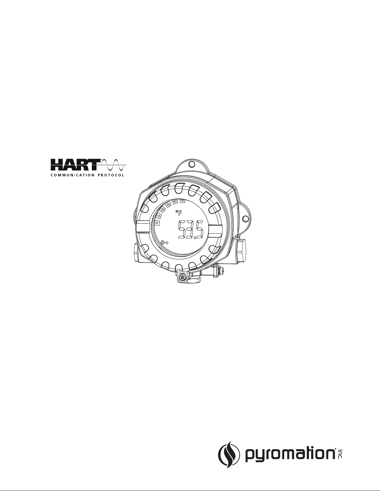
Operating Instructions
Series 642
Field Transmitter HART
®
BA01169O/09/en/01.12
71205730
Device software
01.03
Page 2

Brief overview
For rapid and easy commissioning:
Safety instructions → ä 4
Æ
Installation → ä 7
Æ
Wiring → ä 9
Æ
Display and operating elements → ä 13
Æ
Commissioning → ä 18
Quick SET UP - quick access to device configuration for standard operation
Series 642
2 Pyromation, Inc.
Page 3

Table of contents Series 642
Table of contents
1 Safety instructions . . . . . . . . . . . . . . . . 4
1.1 Designated use . . . . . . . . . . . . . . . . . . . . . . . . . . . . 4
1.2 Installation, commissioning, operation . . . . . . . . . . 4
1.3 Operational safety . . . . . . . . . . . . . . . . . . . . . . . . . 4
1.4 Return . . . . . . . . . . . . . . . . . . . . . . . . . . . . . . . . . . 4
1.5 Notes on safety conventions and icons . . . . . . . . . . 5
2 Identification . . . . . . . . . . . . . . . . . . . . 6
2.1 Device designation . . . . . . . . . . . . . . . . . . . . . . . . . 6
2.2 Scope of delivery . . . . . . . . . . . . . . . . . . . . . . . . . . 6
2.3 Certificates and approvals . . . . . . . . . . . . . . . . . . . . 6
3 Installation . . . . . . . . . . . . . . . . . . . . . . 7
3.1 Quick installation guide . . . . . . . . . . . . . . . . . . . . . 7
3.2 Installation conditions . . . . . . . . . . . . . . . . . . . . . . 8
3.3 Installation . . . . . . . . . . . . . . . . . . . . . . . . . . . . . . 8
3.4 Installation check . . . . . . . . . . . . . . . . . . . . . . . . . . 8
4 Wiring. . . . . . . . . . . . . . . . . . . . . . . . . . 9
4.1 Quick wiring guide . . . . . . . . . . . . . . . . . . . . . . . . . 9
4.2 Connecting the sensor . . . . . . . . . . . . . . . . . . . . . 10
4.3 Connecting the measuring unit . . . . . . . . . . . . . . . 10
4.4 Screening and potential equalization . . . . . . . . . . . 11
4.5 Degree of protection . . . . . . . . . . . . . . . . . . . . . . . 12
4.6 Connection check . . . . . . . . . . . . . . . . . . . . . . . . 12
9 Technical data . . . . . . . . . . . . . . . . . . 33
10 Appendix . . . . . . . . . . . . . . . . . . . . . . 39
10.1 The Callendar - van Dusen Method . . . . . . . . . . . . 39
10.2 Polynomial RTD . . . . . . . . . . . . . . . . . . . . . . . . . . 41
Index. . . . . . . . . . . . . . . . . . . . . . . . . . . . . . 42
5 Operation . . . . . . . . . . . . . . . . . . . . . . 13
5.1 Display and operating elements . . . . . . . . . . . . . . 13
5.2 Local operation . . . . . . . . . . . . . . . . . . . . . . . . . . 14
5.3 Communication using the HART® protocol . . . . . 15
6 Commissioning. . . . . . . . . . . . . . . . . . 18
6.1 Installation check . . . . . . . . . . . . . . . . . . . . . . . . . 18
6.2 Switch on the device . . . . . . . . . . . . . . . . . . . . . . 18
6.3 Quick Setup . . . . . . . . . . . . . . . . . . . . . . . . . . . . . 18
6.4 Device configuration . . . . . . . . . . . . . . . . . . . . . . 19
7 Maintenance. . . . . . . . . . . . . . . . . . . . 28
8 Trouble-shooting . . . . . . . . . . . . . . . . 28
8.1 Trouble-shooting instructions . . . . . . . . . . . . . . . . 28
8.2 Error messages . . . . . . . . . . . . . . . . . . . . . . . . . . . 28
8.3 Application errors without messages . . . . . . . . . 30
8.4 Return . . . . . . . . . . . . . . . . . . . . . . . . . . . . . . . . . 31
8.5 Disposal . . . . . . . . . . . . . . . . . . . . . . . . . . . . . . . . 32
8.6 Software history . . . . . . . . . . . . . . . . . . . . . . . . . . 32
Pyromation, Inc. 3
Page 4

Safety instructions Series 642
NOTICE
1 Safety instructions
1.1 Designated use
• The device is a universal and configurable temperature field transmitter for resistance
thermometers (RTD), thermocouples (TC) and resistance and voltage transmitters. The device is
designed for installation in the field.
• The manufacturer does not accept liability for damage caused by improper or non-designated use.
1.2 Installation, commissioning, operation
Please note the following:
• Mounting, electrical installation, commissioning and maintenance of the device must only be
carried out by trained technical personnel authorised to perform such work by the owneroperator. They must have read and understood these Operating Instructions and must follow the
instructions they contain.
• The device may only be operated by staff authorised and instructed by the owner-operator. Strict
adherence to the instructions in these Operating Instructions is mandatory.
• The installer must ensure that the measuring system is correctly connected in accordance with
the electrical wiring diagrams.
• Observe local regulations governing the opening and repair of electrical devices.
1.3 Operational safety
The measuring device meets the general safety requirements of EN 61010 and the EMC
requirements of EN 61326 as well as NAMUR recommendations NE 21, NE 43 and NE 89.
Power supply
► Power must be fed to the device from an 11 to 40 VDC power supply in accordance with NEC
Class 02 (low voltage/current) with short-circuit power limit to 8 A/150 VA.
Hazardous area
Separate Ex documentation is provided for measuring systems used in hazardous areas. This
documentation is an integral part of these Operating Instructions. The installation instructions and
connection data it contains must be observed!
1.4 Return
To reuse later or in case of repair, the device must be packed in protective packaging, preferably the
original packaging. Repairs must only be carried out by your supplier's service organisation or
specially trained personnel.
Enclose a note describing the fault and the application when sending the unit in for repair.
4 Pyromation, Inc.
Page 5
Series 642 Safety instructions
1.5 Notes on safety conventions and icons
The safety instructions in these Operating Instructions are labelled with the following safety icons
and symbols:
Symbol Meaning
WARNING!
This symbol alerts you to a dangerous situation. Failure to avoid this situation can result
A0011190-EN
in serious or fatal injury.
CAUTION!
This symbol alerts you to a dangerous situation. Failure to avoid this situation can result
A0011191-EN
in minor or medium injury.
NOTICE!
This symbol contains information on procedures and other facts which do not result in
A0011192-EN
personal injury.
Indicates additional information, Tip
A0011193
Pyromation, Inc. 5
Page 6
Identification Series 642
2 Identification
2.1 Device designation
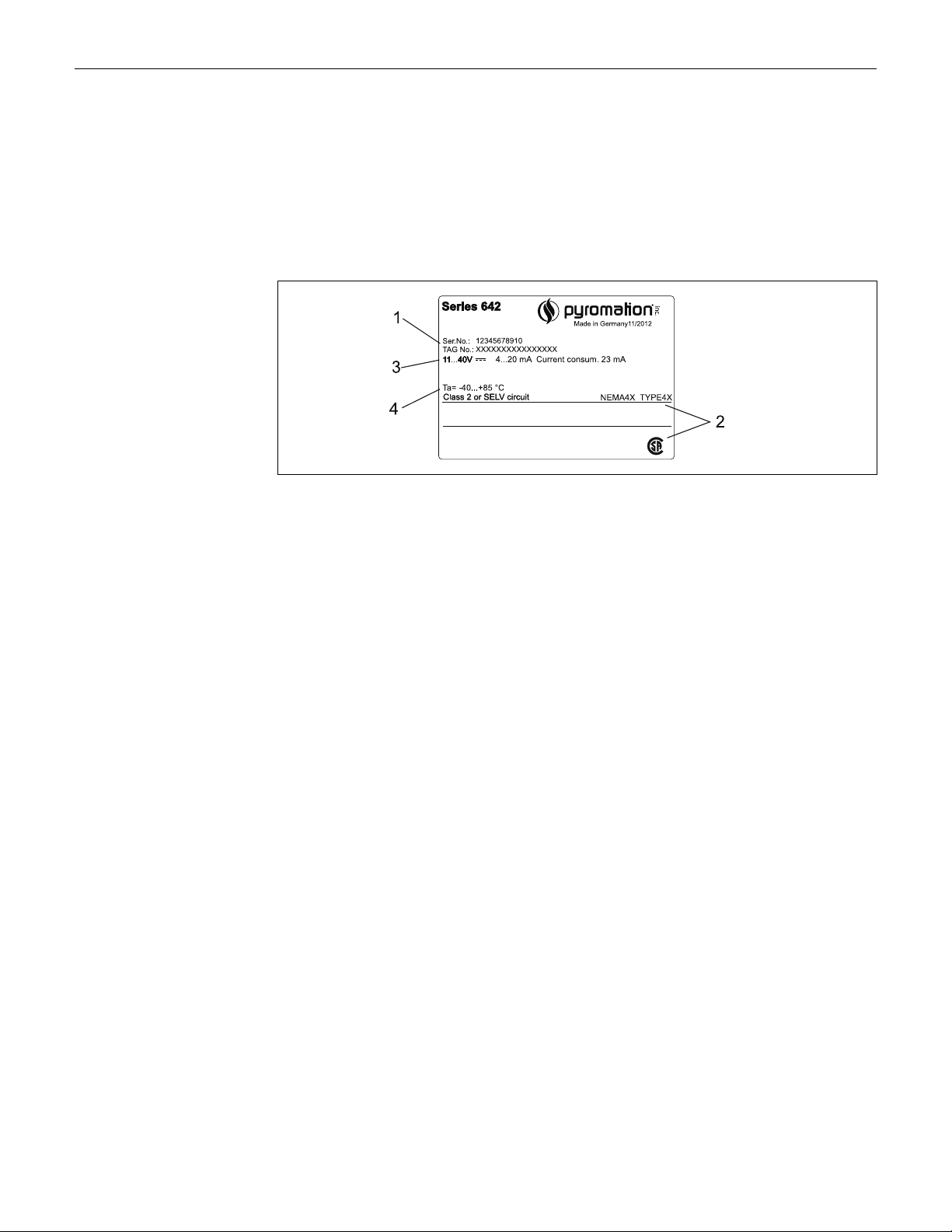
2.1.1 Nameplate
Compare the nameplate on the device with the following diagram:
Fig. 1: Nameplate of the field transmitter (example)
1 Order code and serial number of the device
2 Degree of protection and approvals
3 Power supply and output signal
4 Ambient temperature
2.2 Scope of delivery
The scope of delivery of the field transmitter comprises:
• Temperature field transmitter
• Dummy plug
• Mounting bracket
• Operating Instructions
2.3 Certificates and approvals
CE mark, declaration of conformity
The temperature field transmitter is designed to meet state-of-the-art safety requirements, has been
tested and left the factory in a condition in which it is safe to operate. The device meets the relevant
standards and directives as per IEC 61 010 "Safety requirements for electrical equipment for
measurement, control and laboratory use".
The device described in these Operating Instructions thus meets the legal requirements of the EU
directives. The manufacturer confirms that the device has been tested successfully by affixing the
CE mark.
CSA GP approved
6 Pyromation, Inc.
Page 7
Series 642 Installation
3 Installation
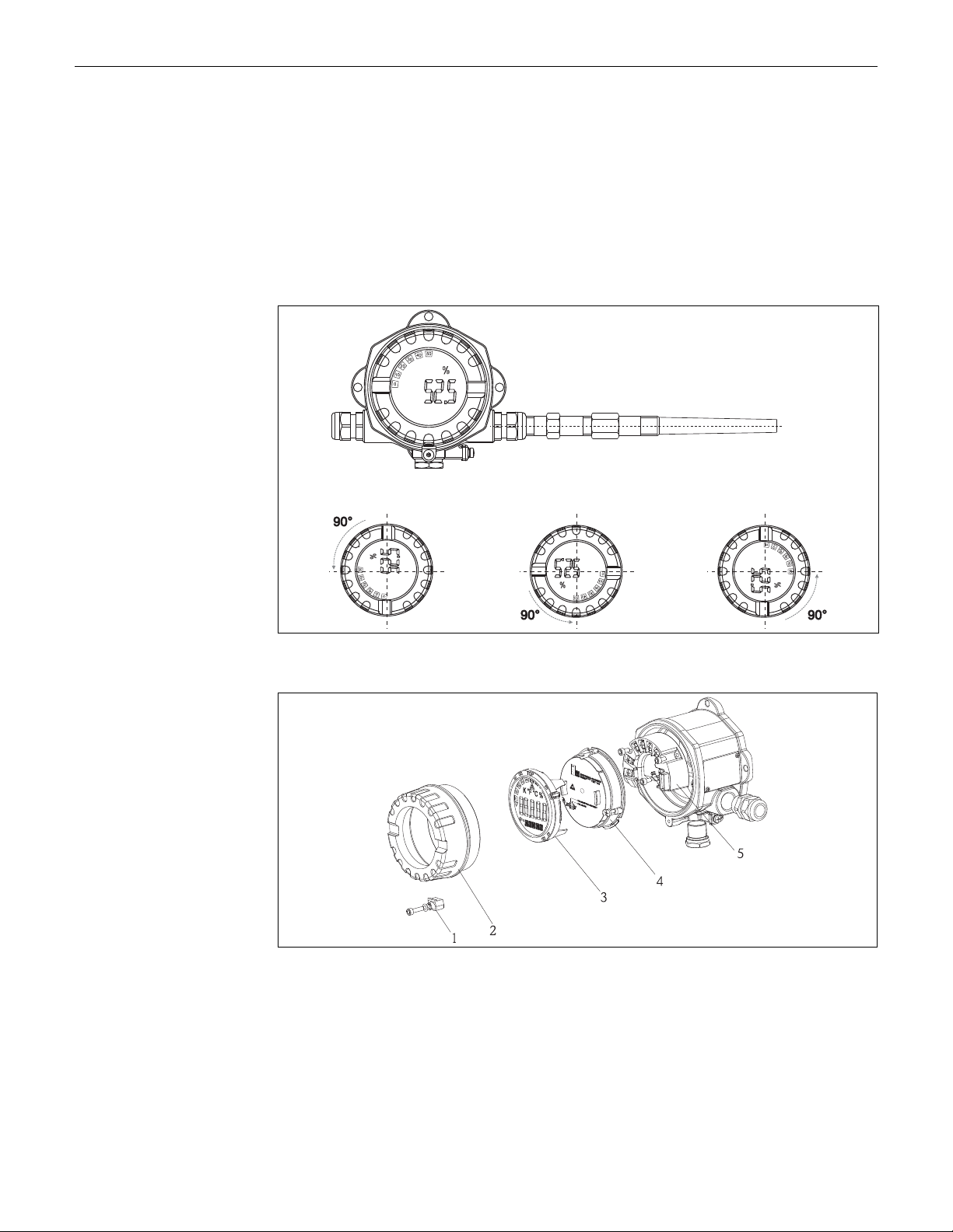
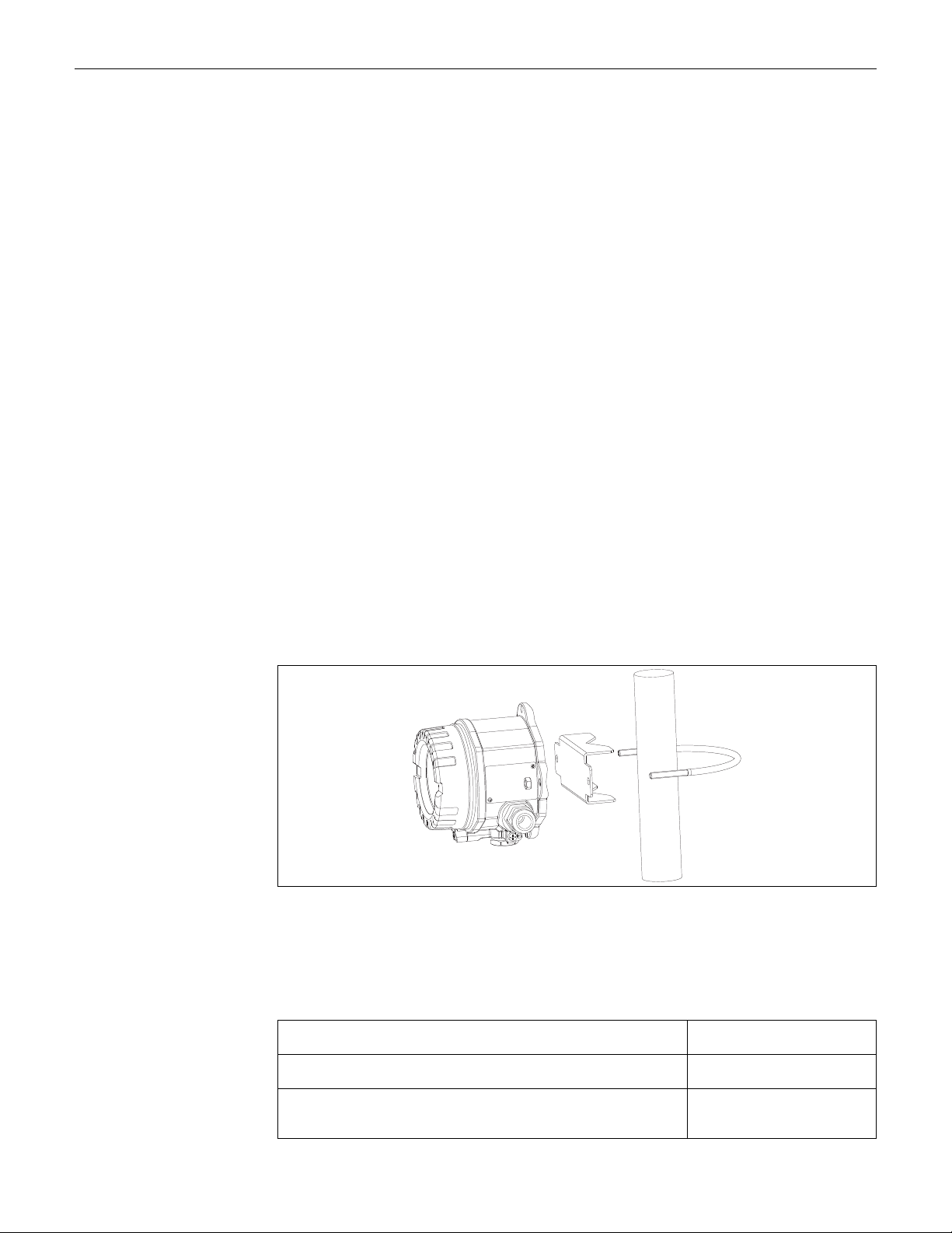
3.1 Quick installation guide
If the sensor is fixed then the unit can be fitted directly to the sensor.
If the sensor is to be mounted at a right angle to the cable gland, swap the dummy plug and cable
gland.
The device can be mounted directly on the wall. A mounting bracket is available for pipe mounting
(see Fig. 4). The illuminated display can be mounted in four different positions (→ å 2):
Fig. 2: Temperature field transmitter with sensor, 4 display positions, can be plugged-in in 90° steps
Fig. 3: Turning the display
1. Remove the cover clamp (Pos. 1).
2. Unscrew the housing cover together with the O-ring (Pos. 2).
3. Remove the display with retainer (Pos. 3) from the electronics module (Pos. 4). Adjust the
display with retainer in 90°stages to your desired position and rearrange it on the particular
slot in the electronics module.
4. Then screw on the housing cover together with the O-ring. Mount the cover clamp.
Pyromation, Inc. 7
Page 8
Installation Series 642
3.2 Installation conditions
3.2.1 Dimensions
The dimensions of the device can be found in chapter 10 ''Technical data".
3.2.2 Installation point
Information on installation conditions, such as ambient temperature, protection classification,
climatic class etc., can be found in chapter 10 "Technical data".
3.3 Installation
3.3.1 Direct wall mounting
Proceed as follows to mount the device directly on wall:
• Drill 2 holes
• Attach the device to the wall with 2 screws (M6).
3.3.2 Pipe installation
The mounting bracket is suited for pipes with a diameter between 1.5" - 3.3".
Proceed as follows to mount the device on a pipe:
• Attach the mounting bracket to the pipe
• The additional mounting plate must be used for pipes with a diameter of 1.5" to 2.2".
• Fix the device to the mounting bracket with the two screws supplied. The mounting plate is not
needed for pipes with a diameter of 2.2" - 3.3".
Fig. 4: Mounting the field transmitter with the mounting bracket, see 'Accessories' section
3.4 Installation check
After installing the device, always run the following final checks:
Device condition and specification Hint
Is the device visibly damaged (visual check)? -
Does the device comply to the measurement point specifications, such as
ambient temperature, measurement range etc.?
8 Pyromation, Inc.
See chapter 10 "Technical data"
Page 9
Series 642 Wiring
NOTICE
NOTICE
4 Wiring
Installation in hazardous area
► When installing Ex-approved devices in a hazardous area please take special note of the
instructions and connection schematics in the respective Ex documentation added to this
operating manual. The local representative is available for assistance if required.
For wiring the device proceed as follows:
1. Remove the cover clamp (→ å 3, item 1).
2. Remove the device cover (→ å 3, item 2).
3. Remove the display from the electronics module (→ å 3, item 3).
4. Open the 2 screws of the electronics unit and remove the electronics unit (→ å 3, item 4).
5. Open the cable gland at the device (→ å 3, item 5).
6. Feed the cable through the opening in the cable gland.
7. Connect the wires (→ å 5).
8. Make sure that the terminal screws are tight. Re-seal the cable gland by screwing the cover
back on.
9. In order to avoid connection errors always take note of the hints given in the section
connection check!
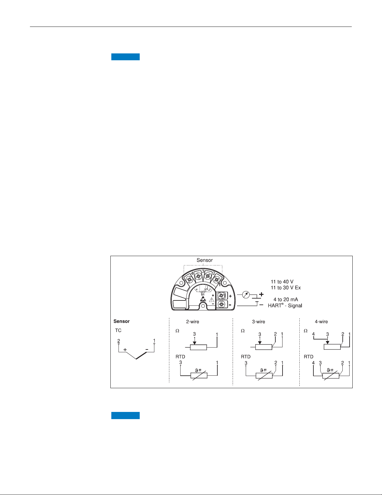
4.1 Quick wiring guide
Terminal layout
Fig. 5: Wiring the field transmitter
ESD - Electrostatic discharge
► Protect the terminals from electrostatic discharge. Failure to observe this may result in
destruction of parts of the electronics.
Pyromation, Inc. 9
Page 10
Wiring Series 642
NOTICE
4.2 Connecting the sensor
Please refer to Section 4.1 "Quick wiring guide" for the terminal assignment of the sensor
connections.
4.3 Connecting the measuring unit
Electronic parts may be damaged
► Switch off power supply before installing or connecting the device. Failure to observe this may
result in destruction of parts of the electronics.
► If the device has not been grounded as a result of the housing being installed, grounding it via
one of the ground screws is recommended.
4.3.1 HART® connection
If the HART
communication resistor must be fitted into the 2-wire supply lines.
For connection hints, please take special notice of the documentation supplied by the
HART
overview”.
®
communication resistance is not built into the power supply, a 250 Ω
®
Communication Foundation, specifically HCF LIT 20: “HART, a technical
Connection using a transmitter power supply
HART® connection with a transmitter power supply
10 Pyromation, Inc.
Page 11
Series 642 Wiring
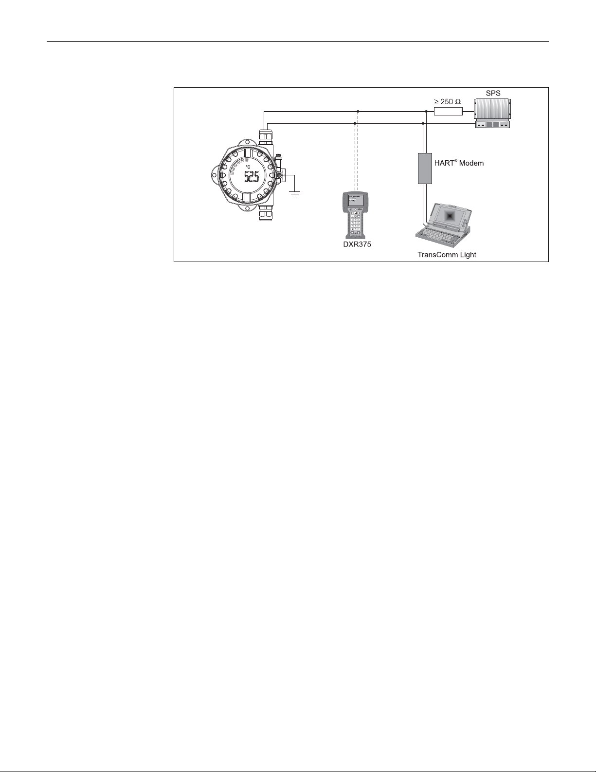
Connection using other power supplies
HART® connection using other power supplies, e. g. a SPS
4.4 Screening and potential equalization
Please take note when installing the device:
If screened (shielded) cables are used then the screen connected to the output (output signal 4 to
20mA) must be at the same potential as the screen at the sensor connection!
When operating in plants with high electromagnetic fields, it is recommended that all cables be
screened using a low ohm ground connection. Due to the possible danger of lightning strikes
screening is also recommended for cables that are run outside buildings!
Pyromation, Inc. 11
Page 12
Wiring Series 642
4.5 Degree of protection
The device conforms to the requirements to IP 67 ingress protection. In order to fulfil an IP 67
degree of protection after installation or service, the following points must be taken into
consideration:
• The housing seals must be clean and undamaged before they are replaced into the sealing rebate.
If they are found to be too dry then they should be cleaned or even replaced.
• All housing screws and covers must be pulled tight.
• The cables used for connection must be of the correct specified outside diameter (e.g. M20 x 1.5,
cable diameter from 8 to 12 mm; 0.315 to 0.47 in).
• Tighten cable gland (→ å 6).
• Loop the cable before placing into the cable entry ("Water sack", → å 6). This means that any
moisture that may form cannot enter the gland. Install the device so that the cable entries are not
facing upwards.
• Cable entries not used are to be blanked off using the blanking plates provided.
• The protective olive must not be removed from the cable gland.
Fig. 6: Connection hints to retain IP 67 protection
4.6 Connection check
After the electrical installation of the device, always perform the following final checks:
Device condition and specification Hint
Are the device or the cables undamaged (visual check)? -
Electrical connection Hint
Is the cable installation correctly separated, with no loops or crossovers? -
Are the cables load relieved? -
Have the cables been correctly connected? Compare with the
connection schematic on the terminals or → Fig. 5.
Are all terminal screws tightened?
Is the cable entry sealed?
Is the housing cover screwed tight?
See connection schematic on the
housing
Visual check
12 Pyromation, Inc.
Page 13
Series 642 Operation
°C
°F
%
K
10
0
20
30
40
50
60
70
80
90
100
!
Ê
Ë
Ì
Í
Î
Ï
Ð
5Operation
5.1 Display and operating elements
5.1.1 Display
Fig. 7: LC display of the field transmitter (illuminated, can be plugged in 90° stages)
5.1.2 Display symbols
Item
Function Description
No.
1 Bargraph display In 10 % stages with indicators for overranging/
2 'Caution' indicator This appears in the event of an error or warning
3 Unit display K, °F, °C or % Unit display for the measured value displayed
4 Measured value display (digit height 20.5 mm) The measured value is displayed. In the event of a warning,
5 Status and information display Indicates which value is currently shown on the display. A
6 'Communication' display The communication symbol appears for read and write
7 'Configuration blocked' display The 'configuration blocked' symbol appears if configuration
underranging. The bargraph display flashes when an error
occurs.
the display switches between the measured value and the
code of the warning. In the event of an error, the error code
is displayed instead of the measured value.
customer-specific text can be entered for PV. In the event
of a warning, 'WARN' is displayed along with the code for
the warning. In the event of an error, 'ALARM' is displayed.
®
access via the HART
via software or hardware is blocked.
protocol
Pyromation, Inc. 13
Page 14
Operation Series 642
NOTICE
5.2 Local operation
5.2.1 Hardware setting
Fig. 8: Hardware settings via jumpers J1, J2 and J3
ESD - Electrostatic discharge
► Protect the terminals from electrostatic discharge. Failure to observe this may result in
destruction of parts of the electronics.
Jumpers J1, J2 and J3 for the hardware setting are located at the electronics module. To set the
jumper, open the threaded joint of the electronics module (opposite the threaded joint of the
connection compartment) and remove the display if necessary.
Hardware locking the configuration with jumper J1
TRANSMITTER SECURITY
ON Configuration locked
OFF Configuration enabled
The hardware setting for configuration locking has priority over the software setting.
Setting the failsafe mode via the hardware with jumper J2
FAILURE MODE
LO ≤ 3.6 mA
HI ≥ 21.0 mA
The failsafe mode set via the jumpers only takes effect if the microcontroller fails.
14 Pyromation, Inc.
Page 15

Series 642 Operation
Please check that the hardware and software setting for the failsafe mode match.
Hardware setting with jumper J3 (only for devices without a display)
If jumper J3 is set, the minimum operating voltage can be reduced from 11 V to 8 V.
5.3 Communication using the HART® protocol
The set-up and measured value read out of the measuring device is done using the HART® protocol.
®
The digital communication is done using the 4 to 20 mA current output HART
(see Figs. 4 and 5).
There are a number of possible set-up methods available to the user:
®
• Operation using the universal handheld module "HART
Communicator DXR375".
• Operation using a PC combined with an operating software, e.g. 'TransComm Light' as well as a
®
modem.
HART
• Operating programs of other manufacturers ('AMS', Fisher Rosemount; 'SIMATIC PDM',
Siemens).
®
If communication errors occur in the Microsoft
®
Windows
2000 operating systems the following measure is to be taken:
Windows NT ® Version 4.0 and
Switch off setting "FIFO active".
In order to do this follow these steps.
®
1. On Windows NT
Version 4.0:
Select the menu point "COM-Port" using the menu "START" ➠ "SETTINGS" ➠ "CONTROL
PANEL" ➠ "PORTS". Using the menu string "SETTINGS" ➠ "ADVANCED" switch the
command "FIFO active" off. Now restart the PC.
®
2. For Windows
2000 and Windows® XP (classic category view):
Select "Advanced settings for COM1" using the menu "START" ➠ "SETTINGS" ➠ "CONTROL
PANEL" ➠ "SYSTEM" ➠ "HARDWARE" ➠ "DEVICE MANAGER" ➠ "PORTS (COM and
LPT)" ➠ "COMMUNICATIONS PORT (COM1)" ➠ "CONNECTION SETTINGS" ➠
"ADVANCED". Deactivate the "Use FIFO buffer". Now restart the PC.
5.3.1 HART® Communicator DXR375
With the HART
menu levels with the aid of the function matrix (→ ä 16). All the device functions are
explained in chapter 6.4.1 "Description of Device Functions".
Procedure:
1. Switch on the handheld module:
– Measuring device not yet connected. The HART
appears for every HART
Information on off-line configuration can be found in the Operating Instructions of the
“Communicator DXR375” handheld module.
– Measuring device is already connected. The 1st menu level of the device function matrix
appears directly (see Fig. 9). All the functions accessible under HART
arranged in this matrix.
2. Select the function group (e.g. Sensor ) and then the desired function, e.g. “Sensor type”.
3. Enter type or change the setting. Then confirm with the function key F4 “Enter”.
4. “SEND” appears via the function key “F2”. Pressing the F2 key transfers all the values entered
with the handheld module to the device measuring system.
Pyromation, Inc. 15
®
handheld module, all device functions are selected by means of various
®
®
programming, i.e. irrespective of the measuring device type.
main menu appears. This menu level
®
are systematically
Page 16

Operation Series 642
Standard
set-up
!
Note!
are marking the Quick Setup menu.
The black highlighted function fields
Min measurm
range
Max
measurm
range
RTD
connection
PV value
in %
Value
Sensor 1
RJ value
Measured
values
Sensor
Output
Safety
settings
Display
Diagnosis
Identification
Service
functions
PV up
range value
Display
Device status
Measuring
point
Tag
Device
release
Descriptor
Serial no.
Software
rev.
Certificates Manufacturer Model Date
Hardware
rev.
Message
Security
locking
Simulation
mode
Simulation
value
Trim
4mA
Trim
20 mA
PV lo
range value
Fault
condition
Display text
Last
diagnostic
Device infos
Default
values
Analog
output
Alarm
hysteresis
Decimal
places
Status
sensor
Config.
changed
Max. value
sensor
Min. value
sensor
Max.
RJ value
Min.
RJ value
HART
Output mode
Num. resp.
preams
Poll
addr.
Corros.
detection
Over-/Under-
range alarm
Mains filter
Filter time
Ambient
alert
Display
interval
AO
PV unit
PV
Sensor type
Sensor
connect.
Cold
junction
External
temp.
2-wire
comp.
Offset
sensor
Meas. unit
sensor
Value
sensor
Serial no.
sensor
Static
Revision Counter
5. With the "F3" function key HOME, you return to the 1st menu level.
Fig. 9: Configuration at the handheld module, using 'Sensor input' as an example’
HART
®
function matrix
16 Pyromation, Inc.
Page 17

Series 642 Operation
•With the HART
disabled. However, you can enable the HART
®
handheld module, all parameters can be read and programming is
®
function matrix by entering 246 in the
SECURITY LOCKING function. The enable status is retained even after a power failure.
®
Delete the release code 246 to lock the HART
• Detailed information can be found in the HART
function matrix again.
®
instruction manual that can be found
in the handheld module transport pouch.
5.3.2 TransComm Light
This is a universally applicable service and configuration software. Connection is made using a
®
HART
• Set-up device functions
• Measured value visualisation
• Device parameter data storage
• Measuring point documentation
Analog output
► The analog output is undefined when downloading the device function parameters from the PC
Further in-depth information to operation via TransComm Light can be found in the online
documentation of the software. TransComm Light can be downloaded free of charge from the
following address:
modem. The operating software offers the user the following possibilities:
NOTICE
configuration software to the device.
www.pyromation.com
5.3.3 Command classification in the HART® protocol
The HART® protocol makes it possible for configuration and diagnostic purposes to transmit
measured and device data between the HART
®
masters such as the handheld module or PC-based operating programmes require so-called
HART
device description files (DD = device descriptions, DTM), these make it possible to access all
®
information in a HART
device. Transmission of such information is done exclusively using
"commands".
There are three command classifications:
• Universal commands
Universal commands are supported and used by all HART
the following functionalities:
®
–Recognising HART
device
– Read out of digital measured values
• Common practice commands:
These general commands offer functions that are supported or used by some but not all field
devices.
• Device specific commands
These commands enable access to device specific functions that are not HART
Such commands access, amongst other things, individual field device information.
Chapter 6.4.2 contains a list of all HART
®
master and the respective field device.
®
devices. Combined are, for example,
®
commands supported.
®
standardised.
Pyromation, Inc. 17
Page 18

Commissioning Series 642
6Commissioning
6.1 Installation check
Before commissioning the measurement point make sure that all final checks have been carried out:
• Checklist “Installation check”
• Checklist “Connection check”
6.2 Switch on the device
Once the power has been connected, the field transmitter is operational.
6.3 Quick Setup
Using the Quick Setup the operator is led through all the most important unit functions, which must
be set up for standard measurement operation of the unit.
Standard set-up
®
Availability in TransComm Light and HART
(symbol
Function + +
PV mode + +
PV unit + +
Sensor
Sensor type + +
Sensor connection + +
Unit + +
OUTPUT
PV lower range value + +
PV upper range value + +
Safety/maintenance functions
Fault condition + +
)
7
communicator DXR375
TransComm Light
7
Alarm ambient temperature + +
Further set-up for special measurement applications are possible (see Section 6.4.1).
18 Pyromation, Inc.
Page 19

Series 642 Commissioning
6.4 Device configuration
6.4.1 Description of device functions
All parameters that can be read out and set-up for the configuration of the temperature transmitter
Availability in TransComm Light, HART
are listed and described in the following tables. The menu structure in the PC configuration software
TransComm Light and in the HART
Factory default setup is shown in bold text.
Function group STANDARD SETTINGS
®
communicator DXR375 (symbol 7) TransComm Light
®
communicator DXR375 are shown in the following tables.
7
PV unit Enter the unit of the PV (= Primary Value)
Availability in TransComm Light, HART
Sensor type
IEC 60751
JIS
IEC 60751
Edison Copper
Winding No. 15
SAMA
Edison Curve No. 7
GOST
Input: ° C, °F, K, R, mV or Ω
The setting PV unit has priority, the selection list of the sensor type is shown
independently from the PV unit.
Function group SENSOR
®
communicator DXR375 (symbol 7) TransComm Light
Sensor type
Pt100
Pt200
Pt100
Pt500
Pt1000
Ni100
Ni1000
Cu10
Pt100
Ni120
Pt50
Pt100
Cu50
Cu100
Meas. range
start
-200 °C (-328 °F)
-200 °C (-328 °F)
-200 °C (-328 °F)
-200 °C (-328 °F)
-200 °C (-328 °F)
-60 °C (-76 °F)
-60 °C (-76 °F)
-100 °C (-148 °F)
-100 °C (-148 °F)
-70 °C (-94 °F)
-200 °C (-328 °F)
-200 °C (-328 °F)
-200 °C (-328 °F)
-200 °C (-328 °F)
Meas. range
full scale value
850 °C (1562 °F)
850 °C (1562 °F)
649 °C (1200.2 °F)
250 °C (482 °F)
250 °C (482 °F)
250 °C (482 °F)
150 °C (302 °F)
260 °C (500 °F)
700 °C (1292 °F)
270 °C (518 °F)
1100 °C (2012 °F)
850 °C (1562 °F)
200 °C (392 °F)
200 °C (392 °F)
min. range
10 K (18 °F)
10 K (18 °F)
10 K (18 °F)
10 K (18 °F)
10 K (18 °F)
10 K (18 °F)
10 K (18 °F)
10 K (18 °F)
10 K (18 °F)
10 K (18 °F)
10 K (18 °F)
10 K (18 °F)
10 K (18 °F)
10 K (18 °F)
++
7
++
Polynomial RTD
Callendar - van
Dusen (Pt100)
-200 °C (-328 °F)
-200 °C (-328 °F)
850 °C (1562 °F)
850 °C (1562 °F)
10 K (18 °F)
10 K (18 °F)
Pyromation, Inc. 19
Page 20

Commissioning Series 642
Function group SENSOR
Availability in TransComm Light, HART® communicator DXR375 (symbol 7) TransComm Light
Sensor type Sensor type
TC Type B
TC Type C
TC Type D
TC Type E
TC Type J
TC Type K
TC Type L
TC Type N
TC Type R
TC Type S
TC Type T
TC Type U
10 to 400 Ω
10 to 2000 Ω
-20 to 100 mV
Specific linearization and sensor matching
Selecting the sensor types 'Callendar-van-Dusen' or 'Polynomial RTD' improves the accuracy of the system or defines user-specific linearisation of resistance
thermometers. A detailed description of the 'Callendar-van-Dusen' method and 'Polynomial RTD' linearisation is provided in the Appendix to these Operating
Instructions.
The selection list of the sensor type is displayed depending on the PV unit. Example: When
selecting a resistance thermometer the PV unit must first be set to Ω.
Sensor connection Input of RTD connection mode.
Input:
•2-wire
• 3-wire
•4-wire
Function is only active on selection of a resistance thermometers (RTD) in the device
function SENSOR TYPE.
Meas. range
start
0 °C (32 °F)
0 °C (32 °F)
0 °C (32 °F)
-270 °C (-454 °F)
-210 °C (-346 °F)
-270 °C (-454 °F)
-200 °C (-328 °F)
-270 °C (-454 °F)
-50 °C (-58 °F)
-50 °C (-58 °F)
-270 °C (-454 °F)
-200 °C (-328 °F)
10 Ω
10 Ω
-20 mV
Meas. range
full scale value
1820 °C (3308 °F)
2320 °C (4208 °F)
2495 °C (4523 °F)
1000 °C (1832 °F)
1200 °C (2192 °F)
1372 °C (2501.6 °F)
900 °C (1652 °F)
1300 °C (2372 °F)
1768 °C (3214.4 °F)
1768 °C (3214.4 °F)
400 °C (752 °F)
600 °C (1112 °F)
400 Ω
2000 Ω
100 mV
min. range
500 K (900 °F)
500 K (900 °F)
500 K (900 °F)
50 K (90 °F)
50 K (90 °F)
50 K (90 °F)
50 K (90 °F)
50 K (90 °F)
500 K (900 °F)
500 K (900 °F)
50 K (90 °F)
50 K (90 °F)
10 Ω
100 Ω
5 mV
++
++
7
Cold junction Selection of the internal (Pt100) or an external comparison
External
temperature
2-wire
compensation
measurement point.
Input:
• internal
• external
Function is only active on selection of a thermo-couple (TC) in the device function SENSOR
TYPE.
Input of the external comparison point measurement value.
put: -40.00 to 85.00 °C (°C, °F, K)
In
0 °C
Function is only active when "external" has been selected in the device function COLD
JUNCTION.
Input of cable resistance compensation on a 2-wire RTD connection.
Input: 0.00 to 30.00 Ω
Function is only active when a 2-wire connection has been selected in the device function
SENSOR CONNECTION.
++
++
++
20 Pyromation, Inc.
Page 21

Series 642 Commissioning
Function group SENSOR
Availability in TransComm Light, HART® communicator DXR375 (symbol 7) TransComm Light
Offset Input of the zero point correction (offset).
Input: -10.00 to 10.00 °C (-18.00 to 18.00 °F)
0.00 °C
Unit Display of measurement unit.
Sensor unit = PV unit
Serial no. sensor Input of the serial number of the sensor connected to this sensor input. + +
Function group OUTPUT
®
Availability in TransComm Light, HART
PV lower range value Input of 4 mA value.
Input: Limitation values see device function SENSOR TYPE.
0 °C
PV upper range value Input of 20 mA value.
Input: Limitation values see device function SENSOR TYPE.
100 °C
Analog output Input of the standard (4 to 20 mA) or inverse (20 to 4 mA) current output signal.
Input:
• 4 to 20 mA
•20 to 4 mA
communicator DXR375 (symbol 7)TransComm Light
++
++
++
++
++
7
7
Filter Selection of the digital filter 1. order (filter time constant).
HART Output/
Multidrop
Input: 0 to 60 s
Preamble Input: Number of response preambles: 5 to 20
5
Device
address
Input: HART address of the temperature transmitters:
0 to 15
If addresses > 0, the temperature transmitter
is in Multidrop mode and the analogue output is set to 4 mA. Device
address is shown on the display in the Multidrop mode
++
-+
Pyromation, Inc. 21
Page 22

Commissioning Series 642
Function group SAFETY/MAINTENANCE
®
Availability in TransComm Light, HART
communicator DXR375 (symbol 7)TransComm Light
7
Fault condition Input of the output signal on sensor rupture or short circuit.
Error current
specification
Alarm hysteresis Transient alarms are suppressed at the analog output (e.g. caused by electrostatic
Alarm ambient
temperature
Corrosion detection Sensor connection cable corrosion can lead to false measured value readings. Therefore
Input:
• max (≥ 21.0 mA)
•min (≤ 3.6 mA)
Input only possible if fault condition = max
Input: 21.6 to 23 mA
21.7 mA
discharge).
Input:
• 0 s
•2 s
•5 s
In the time entered, the last measured value before the alarm is output. If the error is still
present after this period, an alarm is signalled.
An alarm for overshooting/undershooting of permitted ambient temperature is
deactivated here.
Input:
• on
•off
If the ambient temperature alarm is deactivated then the unit will not go into alarm but
will transmit a warning. Change is the responsibility of the user.
our unit offers the possibility to recognise any corrosion before the measured values are
affected. (see chapter 9.2.1).
There are 2 different steps selectable dependent on the application requirements:
• off (warning output just before reaching the alarm set point. This allows for
preventative maintenance/trouble-shooting to be done.)
• on (no warning, immediate alarm)
++
++
++
++
++
Alarm for
undershooting/
overshooting
Mains filter Selection of mains filter
Availability in TransComm Light, HART
DISPLAY Activating the values to be shown on the device display:
Input:
• OFF
If the measuring range is undershot or overshot, the output signal is temperature-linear
up to 3.8 mA or 20.5 mA and remains at these values (as per NAMUR NE43).
•ON
An error is signalled if the measured temperature corresponds to an output value < 3.8
mA or > 20.5 mA, (see 'Fault condition').
z
• 50 H
•60Hz
Function group DISPLAY
®
communicator DXR375 (symbol 7) TransComm Light
++
++
7
22 Pyromation, Inc.
Page 23

Series 642 Commissioning
Function group DISPLAY
• Display: PV (= Primary Value)
• Display: sensor value
• Display: RJ value
• Display Analogue output value
• Display: Status
• Display: percentage value (on/off)
The primary value (PV) is displayed as a
percentage.
In order to activate the values to be shown in the device display using HART
module DXR375: Add (DXR=x) of the values to be displayed and enter the sum.
• Display: time (2s, 4s, 6s, 8s)
• Display: figures after decimal point (0,1,2)
• Display PV text (customer specific text, 8 characters)
Function group DIAGNOSTICS
®
Availability in TransComm Light, HART
Diagnostics Display of information required for device diagnostics.
• Device status or error code
(See chapter 9.2 "Error messages")
• Last error code (status) or previous error code
(See chapter 9.2 "Error messages")
• Status sensor (0 = no error; 0 ≠ error)
• Configuration changed
communicator DXR375 (symbol 7)TransComm Light
(DXR=1)
(DXR=2)
(DXR=8)
(DXR=16)
(DXR=32)
off (DXR=0)
on (DXR=64)
®
handheld
+
+
+
+
+
+
+
+
+
+
+
+
+
+
+
+
+
+
7
+
+
+
+
+
+
+
Diagnostics • Static revision
Availability in TransComm Light, HART
Measuring point
Input and display of the information relating to the measuring point identification
The "Static revision" is increased on every parameter change. This is for compliance to
21 CFR Part 11, showing that no further parameter changes have been made.
• Sensor max. value
•Sensor min. value
• RJ max. value
•RJ min. value
Display of the maximum process value. The process value will be accepted after starting
the measurement.
Display of the minimum process value. The process value will be accepted after starting
the measurement.
Display of the maximum and minimum measured temperatures of the internal Pt100 DIN
B comparison measurement point.
• Maximum process value is changed to the actual process value on write access. On
reset to factory default value the default value is entered -9999.99.
• Minimum process value is changed to the actual process value on write access. On
reset to factory default value the default value is entered +9999.99.
Function group IDENTIFICATION
®
communicator DXR375 (symbol 7)TransComm Light
-
+
+
+
+
-
+
+
+
+
7
Pyromation, Inc. 23
Page 24

Commissioning Series 642
Function group IDENTIFICATION
TAG Input: 8 characters + +
Descriptor Input: 16 characters + +
Message Input: 32 characters - +
Device information
Display of the information relating to the device identification
Device release Display of device release - +
Serial number 11 digit display of the device serial number
Software rev. Display of the software version + +
Hardware rev. Display of the hardware version + +
Certificates Display of device approvals - +
Device
Display of the information relating to the HART
Manufacturer Manufacturer’s identification: Pyromation Inc. - +
Model Device type identification: Series 642 - +
Date Individual use of this parameter - +
Hardware Rev. HART Device Revision - +
(equal to that on the legend plate).
®
device identification
++
24 Pyromation, Inc.
Page 25

Series 642 Commissioning
Function group SERVICE FUNCTIONS
®
Availability in TransComm Light, HART
communicator DXR375 (symbol 7) TransComm Light
7
Security locking Set-up release code.
Reset to default Reset to factory default values.
Output simulation Activate simulation mode.
Simulation value Input of the simulation value (current).
User calibration
(trim) analog output
Availability in TransComm Light, HART
Input:
• Lock = 0
•Release = 246
Input: 642
0
Input:
• OFF
•ON
Input: 3.58 to 23 mA
For changing the 4 or 20 mA value by ± 0.150 mA
• Trimming 4 mA
• Trimming 20 mA
Function group MEASURED VALUES
®
communicator DXR375 (symbol 7)TransComm Light
++
++
++
++
++
7
PV PV value ++
AO PV value in mA - +
PV % PV value in % - +
Sensor Sensor process value - +
Internal temperature Internal temperature of the device - +
Pyromation, Inc. 25
Page 26

Commissioning Series 642
6.4.2 Supported HART® commands
r = read access, w = write access
No. Description Access
Universal Commands
00 Read unique identifier r
01 Read primary variable r
02 Read p.v. current and percent of range r
03 Read dynamic variables and p.v. current r
06 Write polling address w
11 Read unique identifier associated with tag r
12 Read message r
13 Read tag, descriptor, date r
14 Read primary variable sensor information r
15 Read primary variable output information r
16 Read final assembly number r
17 Write message w
18 Write tag, descriptor, date w
19 Write final assembly number w
Common practice
34 Write primary variable damping value w
35 Write primary variable range values w
38 Reset configuration changed flag w
40 Enter/exit fixed primary variable current mode w
42 Perform master reset w
44 Write primary variable units w
48 Read additional device status r
59 Write number of response preambles w
Device specific
144 Read matrix parameter r
145 Write matrix parameter w
231 Check Device Status r
•HART
®
command No. 48 (HART-Cmd #48)
Apart from the response code and the device status byte, the field transmitter calls up a detailed
diagnosis by means of Cmd #48. This diagnosis is 8 bytes long.
26 Pyromation, Inc.
Page 27

Series 642 Commissioning
Byte Contents Meaning
1
2 0 x 01 warning: backup switched on
Overall device status
3 0 x 01 information: device starting
4 0 x 40 global bit for a warning
5
Status channel 1
7
8 Device operating mode Always 0
Extended device status
0 x 01 error: EEPROM
0 x 02 error: ADC
0 x 04 error: channel 1
0 x 10 error: comparison
measurement point
0 x 20 error: HART ASIC
0 x 40 warning: measured value range undershoot
0 x 80 warning: measured value range overshoot
0 x 02 information: maintenance necessary
0 x 04 information: drift too small/large
0 x 08 information: corrosion at terminals
0 x 10 information: ambient temperature too high/low
0 x 20 information: output current at fixed value
0 x 40 information: no LCD connected or LCD error
0 x 80 information: upload/download active
0 x 02 error: supply voltage too low
0 x 80 global bit for an error
0 x 01 warning corrosion
0 x 02 corrosion
0 x 04 sensor rupture
0 x 08 sensor short circuit
0 x 10 range undershoot
0 x 20 range overshoot
0 x 40 channel not operational
0 x 80 error A/D conversion
0 x 01 maintenance necessary
0 x 02 warnings / error present
•HART® command No. 231 (HART-Cmd #231)
The classified diagnosis of the device can be checked by means of this command. Fault classes
according to GMA VDE NAMUR 2650 guidelines:
Byte Contents Meaning
1 Information acc. to GMA VDE
NAMUR 2650
2+3 Device error messages, see
section 9.2
0x01 -F- Fault
0x02 -C- Device in service mode
0x03 -M- Maintenance required
0x04 -S- Out of specification
Fault classification see Section 9.2 Error messages.
Pyromation, Inc. 27
Page 28

Maintenance Series 642
7 Maintenance
No special maintenance work is required on the device.
8 Trouble-shooting
8.1 Trouble-shooting instructions
Always begin trouble-shooting with the following checklists if errors occur after commissioning or
during measuring operation. The questions guide you to the cause of the error and the appropriate
remedial action.
8.2 Error messages
Fault code Cause Action/cure Mode
0 No error, warning - -
10 Hardware error (device defective) Replace device F
13 Reference measuring point defective Replace device F
15 EEprom defective Replace device F
16 A/D converter defective Replace device F
17 Ambient temperature limit overshot Electronics possibly damaged by
overshooting ambient temperature limits,
return electronics to manufacturer for
checking
19 Supply voltage too low Check supply voltage; check connection
50 Sensor cable open circuit Check sensor *
51 Sensor short-circuit Check sensor *
52 Sensor corrosion Check sensor *
53 Outside sensor range Wrong sensor type for application *
81 Alarm: measuring range undershoot Measuring range poss. set too small F
82 Alarm: measuring range overshoot Measuring range poss. set too small F
106 Warning: upload/download active - C
107 Warning:
Output simulation active
201 Warning:
Measured value too low
202 Warning:
measured value too large
203 Warning:
Ambient temperature limit overshot
206 Warning:
Sensor corrosion
208 Reset device to factory default values - 0
wires for corrosion
Deactivate output simulation C
Change PV lower range value M
Change PV upper range value M
Electronics possibly damaged by
overshooting ambient temperature limits,
return electronics to manufacturer for
checking
Check sensor M
0, F
F
0
1)
28 Pyromation, Inc.
Page 29

Series 642 Trouble-shooting
Fault code Cause Action/cure Mode
209 Device initialization - 0
+1000 Additional errors active Eliminate error displayed
1) The modes have the following meaning: F: Fault, C: Device in service mode, M: Maintenanca required, S: Out of
specification, *: depends on mode (F or M). See also section 6.4.2 Supported HART
®
commands.
1)
If several errors are present, the error with the highest priority is output. Once this error is
eliminated, the next error is output! An offset of 1000 indicates that more than one error is
present.
Device behavior in event of sensor error
In the event of a warning or error, the "Caution" symbol appears on the display and the error code
is shown. If an error occurs, the bargraph also flashes on the display and only the error code is
displayed and not the measured value. (See also Section 5.2).
8.2.1 Corrosion detection
Corrosion detection only for RTD 4-wire connection.
Sensor connection cable corrosion can lead to false measured value readings. Therefore our unit
offers the possibility to recognize any corrosion before the measured values are affected.
There are 2 different steps selectable dependent on the application requirements:
• off (warning output just before reaching the alarm set point. This allows for preventative
maintenance/trouble-shooting to be done.)
• on (no warning, immediate alarm)
The following table describes how the device behaves when the resistance changes in a sensor
connection line, depending on whether on or off is selected.
1)
RTD
off --- WARNING ALARM
on --- ALARM ALARM
1) Pt100 = 100 Ω at 0°C / Pt1000 = 1000 Ω at 0°C
TC < ≈ 10 kΩ 10 kΩ ≈ < x< ≈ 15 kΩ > ≈ 15 kΩ
off --- WARNING
on --- ALARM ALARM
1) If the ambient temperature is very high, it is possible to have a measured error 3 times that of the specified value.
< ≈ 2 kΩ 2 kΩ ≈ < x< ≈ 3 kΩ > ≈ 3 kΩ
1)
ALARM
The sensor resistance can have an effect on the resistance data in the table. If all the sensor
connection line resistances are increased simultaneously, the values described in the table are
halved. In corrosion detection, it is assumed this is a slow process with a continuous increase in
resistance.
Pyromation, Inc. 29
Page 30

Trouble-shooting Series 642
8.2.2 Monitoring the supply voltage
If the necessary supply voltage is undershot, the analog output value drops approx. 3 s ≤ 3.6 mA.
Error code 19 appears on the display. Then the device attempts to output the normal analog output
value again. If the supply voltage remains too low, the analog output value drops again to ≤ 3.6 mA.
This prevents the device from constantly outputting an incorrect analog output value.
8.3 Application errors without messages
8.3.1 Application errors in general
Error pattern Cause Action/cure
No communication No power supply via the
2-wire line
250 Ω communication resistance missing See Section 4.3.1 "Connecting HART
Supply voltage too low (<11 V or 8 V
without display with jumper J3)
Interface cable defective Check interface cable
Interface defective Check interface of your PC
Device defective Replace device
Connect connecting cables correctly in
accordance with terminal plan (polarity)
®
Check power supply
"
8.3.2 Application errors for RTD connection
Pt100/Pt500/Pt1000/Ni100
Error pattern Cause Action/cure
Error current
(≤ 3.6 mA or ≥ 21 mA)
Sensor defective Check sensor
Incorrect RTD connection Connect connecting cables correctly
(terminal plan)
Incorrect 2-wire line connection Connect connecting cables correctly in
Faulty device programming (number of
wires)
Programming Incorrect sensor type configured in the
Device defective Replace device
accordance with terminal plan (polarity)
Change SENSOR CONNECTION device
function
SENSOR TYPE device function; change to
correct sensor type
30 Pyromation, Inc.
Page 31

Series 642 Trouble-shooting
Error pattern Cause Action/cure
Measured value is incorrect/
inaccurate
Orientation of the sensor is incorrect Install sensor properly
Heat conducted by sensor Observe face-to-face length of the sensor
Faulty device programming (number of
wires)
Faulty device programming (scaling) Change scaling
Incorrect RTD configured Change SENSOR TYPE device function
Sensor connection (2-wire) Check sensor connection
Line resistance of sensor (2-wire) was not
compensated
Offset incorrectly configured Check offset
Change SENSOR CONNECTION device
function
Compensate line resistance
8.3.3 Application errors for TC connection
Error pattern Cause Action/cure
Error current
(≤ 3.6 mA or ≥ 21 mA)
Sensor connected incorrectly Connect sensor in accordance with
terminal plan (polarity)
Sensor defective Check sensor
Programming Incorrect sensor type configured in the
SENSOR TYPE device function; set correct
thermocouple
Device defective Replace device
Error pattern Cause Action/cure
Measured value is incorrect/
inaccurate
Orientation of the sensor is incorrect Install sensor properly
Heat conducted by sensor Observe face-to-face length of the sensor
Faulty device programming (scaling) Change scaling
Wrong thermocouple type (TC) configured Change SENSOR TYPE device function
Incorrect comparison measurement point
configured
Offset incorrectly configured Check offset
Interference through thermo-wire welded
in thermowell (interference voltage
coupled in)
See Section "Description of device
functions"
Use sensor that does not have a weld-on
thermo-wire
8.4 Return
To reuse later or in case of repair, the device must be packed in protective packaging, preferably the
original packaging. Repairs must only be carried out by your supplier's service organisation or
specially trained personnel.
Enclose a note describing the fault and the application when sending the unit in for repair.
Pyromation, Inc. 31
Page 32

Trouble-shooting Series 642
8.5 Disposal
The device contains electronic components and must, therefore, be disposed of as electronic waste
in the event of disposal. Please observe in particular the local waste disposal regulations of your
country.
8.6 Software history
SW Revision
The software version in the Operating Instructions indicates the device release history: XX.YY.ZZ
(example 01.02.01).
XX Change in the main version.
YY Change in the functionality and operation.
ZZ Debugging and internal modifications.
SW Revision, date Operation, documentation Modifications
01.03.01, 03/2005 Compatible with:
01.03.03, 12/2006 - Internal SW
No longer compatible. Changes to device and Operating Instructions.
Compatible. Changes to Operating Instructions.
No changes to Operating Instructions.
• HART Communicator DXR375 (from OS1.6)
• (TransComm Light as of version 1.0.
MS (as of version 5.0)
• A
• PDM (as of version 5.1)
15.0)
modifications.
32 Pyromation, Inc.
Page 33

Series 642 Technical data
9 Technical data
9.0.1 Input
Measured variable Temperature (temperature linear transmission behaviour), resistance and voltage
Measuring range The transmitter records different measuring ranges depending on the sensor connection and input
signals.
Input Designation Measuring range limits Min. span
Resistance thermometer (RTD)
To IEC 60751
(α = 0.00385)
To JIS C1604-81
(α = 0.003916)
To DIN 43760
(α = 0.006180)
To Edison Copper Winding No.15
(α = 0.004274)
To SAMA
(α = 0.003923)
To Edison Curve
(α = 0.006720)
To GOST
(α = 0.003911)
To GOST
(α = 0.004278)
Pt100
Pt200
Pt500
Pt1000
Pt100
Ni100
Ni1000
Cu10
Pt100
Ni120
Pt50
Pt100
Cu50, Cu100
Polynomial RTD
Pt100 (Callendar - van Dusen)
• Type of connection: 2-wire, 3-wire or 4-wire connection
• With 2-wire circuit, compensation of wire resistance possible (0 to 30 Ω)
• With 3-wire and 4-wire connection, sensor wire resistance to max. 50 Ω per wire
• Sensor current: ≤ 0.3 mA
-200 to 850 °C (-328 to 1562 °F)
-200 to 850 °C (-328 to 1562 °F)
-200 to 250 °C (-328 to 482 °F)
-200 to 250 °C (-238 to 482 °F)
-200 to 649 °C (-328 to 1200 °F)
-60 to 250 °C (-76 to 482 °F)
-60 to 150 °C (-76 to 302 °F)
-100 to 260 °C (-148 to 500 °F)
-100 to 700 °C (-148 to 1292 °F)
-70 to 270 °C (-94 to 518 °F)
-200 to 1100 °C (-328 to 2012 °F)
-200 to 850 °C (-328 to 1562 °F)
-200 to 200 °C (-328 to 392 °F)
-200 to 850 °C (-328 to 1562 °F)
-200 to 850 °C (-328 to 1562 °F)
10 K (18 °F)
10 K (18 °F)
10 K (18 °F)
10 K (18 °F)
10 K (18 °F)
10 K (18 °F)
10 K (18 °F)
10 K (18 °F)
10 K (18 °F)
10 K (18 °F)
10 K (18 °F)
10 K (18 °F)
10 K (18 °F)
10 K (18 °F)
10 K (18 °F)
Resistance transmitter Resistance Ω 10 to 400 Ω
10 to 2000 Ω
Thermocouples (TC)
To NIST monograph 175,
IEC 584
to ASTM E988
to DIN 43710
Type B (PtRh30-PtRh6)
Type E (NiCr-CuNi)
Type J (Fe-CuNi)
Type K (NiCr-Ni)
Type N (NiCrSi-NiSi)
Type R (PtRh13-Pt)
Type S (PtRh10-Pt)
Type T (Cu-CuNi)
Type C (W5Re-W26Re)
Type D (W3Re-W25Re)
Type L (Fe-CuNi)
Type U (Cu-CuNi)
• Internal cold junction (Pt100); accuracy of cold junction: ± 1 K
• Max. sensor resistance 10 kΩ (if sensor resistance is greater than 10 kΩ, error message as per NAMUR NE 89)
1)
0 to +1820 °C (32 to 3308 °F)
-270 to +1000 °C (-454 to 1832 °F)
-210 to +1200 °C (-346 to 2192 °F)
-270 to +1372 °C (-454 to 2501 °F)
-270 to +1300 °C (-454 to 2372 °F)
-50 to +1768 °C (-58 to 3214 °F)
-50 to +1768 °C (-58 to 3214 °F)
-270 to +400 °C (-454 to 752 °F)
0 to +2320 °C (32 to 4208 °F)
0 to +2495 °C (32 to 4523 °F)
-200 to +900 °C (-328 to 1652 °F)
-200 to +600 °C (-328 to 1112 °F)
10 Ω
100 Ω
500 K (900 °F)
50 K (90 °F)
50 K (90 °F)
50 K (90 °F)
50 K (90 °F)
500 K (900 °F)
500 K (900 °F)
50 K (90 °F)
500 K (900 °F)
500 K (900 °F)
50 K (90 °F)
50 K (90 °F)
Pyromation, Inc. 33
Page 34

Technical data Series 642
Input Designation Measuring range limits Min. span
Voltage transmitter (mV) Millivolt transmitter (mV) -20 to 100 mV 5 mV
1) Increasing inaccuracy for temperatures < 300 °C (< 572 °F)
9.0.2 Output
Output signal Analog 4 to 20 mA, 20 to 4 mA
Signal on alarm • Underranging:
Linear drop to 3.8 mA
•Overranging:
Linear rise to 20.5 mA
• Sensor break; sensor short-circuit (not for thermocouples TC):
≤ 3.6 mA or ≥ 21.0 mA (configurable 21.6 mA to 23 mA)
Load Max. (V
Linearisation/transmission
Temperature linear, resistance linear, voltage linear
power supply
- 11 V) / 0.022 A (current output)
behaviour
st
Filter 1
order digital filter: 0 to 60 s
Galvanic isolation U = 2 kV AC (input/output)
Input current required ≤ 3.5 mA
Current limit ≤ 23 mA
Switch-on delay 4 s (during switch-on operation I
= 4 mA)
a
34 Pyromation, Inc.
Page 35

Series 642 Technical data
NOTICE
9.0.3 Power supply
Supply voltage Ub= 11 to 40 V (8 to 40 V without display), reverse polarity protection
Power supply
► Power must be fed to the device from an 11 to 40 VDC power supply in accordance with NEC
Class 02 (low voltage/current) with short-circuit power limit to 8 A/150 VA.
Residual ripple Perm. residual ripple U
9.0.4 Accuracy
Response time 1 s
Reference operating
conditions
Maximum measured error
Calibration temperature: +25 °C, ± 5 K; (+77 °F, ± 9 °F)
Resistance thermometer (RTD)
Thermocouples (TC)
1) % relates to the set span. Accuracy = digital + D/A accuracy
≤ 3 V at Ub ≥ 13.5 V, f
ss
Designation
Cu100, Pt100, Ni100, Ni120
Pt500
Cu50, Pt50, Pt1000, Ni1000
Cu10, Pt200
K, J, T, E, L, U
N, C, D
S, B, R
max.
= 1 kHz
Accuracy
Digital D/A
0.2 K (0.36 °F)
0.6 K (1.08 °F)
0.4 K (0.72 °F)
2 K (3.6 °F)
typ. 0.5 K (0.9 °F)
typ. 1 K (0.18 °F)
typ. 2 K (3.6 °F)
1)
0.02%
0.02%
0.02%
0.02%
0.02%
0.02%
0.02%
Measuring range
Resistance transmitter (Ω)
Voltage transmitter (mV) -20 to 100 mV ± 20 μV 0.02%
1) % relates to the set span. Accuracy = digital + D/A accuracy
Physical input range of the sensors
10 to 400 Ω Cu10, Cu50, Cu100, polynomial RTD, Pt50, Pt100, Ni100, Ni120
10 to 2000 Ω Pt200, Pt500, Pt1000, Ni1000
-20 to 100 mV Thermocouple type: C, D, E, J, K, L, N
-5 to 30 mV Thermocouple type: B, R, S, T, U
10 to 400 Ω
10 to 2000 Ω
Digital D/A
± 0.08 Ω
± 1.6 Ω
Accuracy
1)
0.02%
0.02%
Repeatability 0.03% of the physical input range (15 Bit)
Resolution A/D conversion: 18 Bit
Pyromation, Inc. 35
Page 36

Technical data Series 642
Influence of supply voltage ≤ ±0.005%/V deviation from 24 V, related to the full scale value
Long-term stability ≤ 0.1 K (0.18 °F)/year or ≤ 0.05%/year
Data under reference conditions. % relates to the set span. The larger value applies.
Influence of ambient
temperature (temperature
drift)
Total temperature drift = input temperature drift + output temperature drift
Effect on the accuracy when ambient temperature changes by 1 K (1.8 °F)
Input 10 to 400 Ω 0.002% of measured value
Input 10 to 2000 Ω 0.002% of measured value
Input -20 to 100 mV typ. 0.002% of measured value (maximum value = 1.5 x typ.)
Input -5 to 30 mV typ. 0.002% of measured value (maximum value = 1.5 x typ.)
Output 4 to 20 mA typ. 0.002% of measured value (maximum value = 1.5 x typ.)
Typical sensor resistance change when process temperature changes by 1 K (1.8 °F):
Cu10: 0.04 Ω Pt200: 0.8 Ω Ni120: 0.7 Ω Cu50: 0.2 Ω Pt50: 0.2 Ω
Cu100, Pt100: 0.4 Ω Pt500: 2 Ω Pt1000: 4 Ω Ni100: 0.6 Ω Ni1000: 6 Ω
Typical change in thermoelectric voltage when process temperature changes by 1 K (1.8 °F):
B: 10 μVC: 20 μVD: 20 μVE: 75 μVJ: 55 μVK: 40 μV
L: 55 μVN: 35 μVR: 12 μVS: 12 μV T: 50 μVU: 60 μV
Examples for calculating the accuracy:
• Example 1
Input temperature drift Δϑ = 10 K (18 °F), Pt100, span 0 to 100 °C (32 to 212 °F)
Maximum process value: 100 °C (212 °F)
Measured resistance value: 138.5 Ω (see IEC 60751)
Typ. influence in Ω: (0.002% of 138.5 Ω) * 10 = 0.0277 Ω
Conversion Ω to °C: 0.0277 Ω / 0.4 Ω/K = 0.07 K (0.013 °F)
• Example 2
Input temperature drift Δϑ = 10 K (18 °F), thermocouple type K with span 0 to 600 °C (32 to
1112 °F)
Maximum process value: 600 °C (1112 °F)
Measured thermoelectric voltage: 24905 μV (see IEC584)
Typ. influence in μV: (0.002% of 24905 μV) * 10 = 5 μV
Conversion Ω to °C: 5 μV / 40 μV/K = 0.12 K (0.216 °F)
• Example 3
Output temperature drift Δϑ = 10 K (18 °F), measuring range 0 to 100 °C (32 to 212 °F)
Span: 100 K (180 °F)
Typical influence: (0.002% of 100 K) * 10 = 0.02 K; (0.002% of 180 °F) * 10 = 0.036 °F
Δϑ = deviation of ambient temperature from the reference operating condition
Total measuring point error = max. possible measured error + temperature sensor error
Influence of cold junction Pt100 DIN IEC 60751 Cl. B (internal cold junction with thermocouples TC)
36 Pyromation, Inc.
Page 37

Series 642 Technical data
9.0.5 Environment
Ambient temperature limits • Without display: -40 to +85 °C (-40 °F to +185 °F)
• With display: -40 to +80 °C (-40 °F to +176 °F)
For use in hazardous areas, see Ex certificate
At temperatures < -4 °F (-20 °C) the display may react slowly. Readability of the display
cannot be guaranteed at temperatures < -30 °C (-22 °F).
Storage temperature • Without display: -40 to +100 °C (-40 °F to +212 °F)
• With display: -40 to +85 °C (-40 °F to +185 °F)
Operating height Up to 2000 m above MSL
Climate class As per EN 60 654-1, Class C
Degree of protection IP 67, NEMA 4x
Shock and vibration resistance 3g / 2 to 150 Hz as per IEC 60 068-2-6
Electromagnetic compatibility
(EMC)
Condensation Permitted
Installation category I
Pollution degree 2
Interference immunity and interference emission as per EN 61 326-1 (IEC 1326) and NAMUR NE
21
0.08...2 GHz 10 V/m; 1.4...2 GHz 30 V/m to EN 61000-4-3
Pyromation, Inc. 37
Page 38

Technical data Series 642
9.0.6 Mechanical construction
Design, dimensions
Fig. 10: Dimensions in inches (mm in brackets)
• Display rotatable in 90 stages
Weight Approx. 1.6 kg (3.53 lb) (aluminum housing)
Material • Housing: die-cast aluminum housing AlSi10Mg with powder coating on polyester basis
• Nameplate: 1.4301 (AISI 304)
Terminals Cables / wires up to max. 2.5 mm
2
(AWG 13) plus ferrule
9.0.7 Certificates and approvals
CE mark The device meets the statutory requirements of the EC directives. The manufacturer confirms
successful testing of the device by affixing to it the CE mark.
Hazardous area approval Information about currently available hazardous area versions (FM, CSA, etc.) can be supplied by
your representative office on request. All explosion protection data are given in a separate
documentation which is available upon request.
CSA GP CSA General Purpose
Other standards and
guidelines
• IEC 60529: Degree of protection through housing (IP code)
• IEC 61010: Protection measures for electrical equipment for measurement, control, regulation
and laboratory procedures
• IEC 1326: Electromagnetic compatibility (EMC requirements)
• NAMUR: Association for Standards for Control and Regulation in the Chemical Industry
38 Pyromation, Inc.
Page 39

Series 642 Appendix
R
T
R01 AT BT2CT 100–()T
3
++ +[]=
a
R
100
R0–
100 R
0
·
---------------------
=
R
T
R
0
R0a T·+=
T
R
T
R0–
R
0
a·
--------------------
=
d
T
h
RThR0–
R
0
a·
-----------------------
–
T
h
100
-------- -
1–
èø
æö
T
h
100
-------- -
èø
æö
--------------------------------------
=
RTR0R0a T(d
T
100
-------- -
1–
èø
æö
–
T
100
-------- -
èø
æöøö
++=
10 Appendix
10.1 The Callendar - van Dusen Method
It is a method to match sensor and transmitter to improve the accuracy of the measurement system.
According to IEC 60751, the non-linearity of the platinum thermometer can be expressed as (1):
in which C is only applicable when T < 0 °C.
The coefficients A, B, and C for a standard sensor are stated in IEC 60751. If a standard sensor is
not available or if a greater accuracy is required than can be obtained from the coefficients in the
standard, the coefficients can be measured individually for each sensor. This can be done e.g. by
determining the resistance value at a number of known temperatures and then determining the
coefficients A, B, and C by regression analysis.
However, an alternative method for determination of these coefficients exists. This method is based
on the measuring of 4 known temperatures:
•Measure R
•Measure R
•Measure R
•Measure R
Calculation of α
First the linear parameter α is determined as the normalized slope between 0 and 100 °C (2):
If this rough approximation is enough, the resistance at other temperatures can be calculated as (3):
and the temperature as a function of the resistance value as (4):
Calculation of δ
Callendar has established a better approximation by introducing a term of the second order, δ , into
the function. The calculation of δ is based on the disparity between the actual temperature, T
the temperature calculated in (4) (5):
at T0 = 0 °C (the freezing point of water)
0
at T
100
at Th = a high temperature (e.g. the freezing point of zink, 419.53 °C)
h
at Tl = a low temperature (e.g. the boiling point of oxygen, -182.96 °C)
l
= 100 °C (the boiling point of water)
100
, and
h
Pyromation, Inc. 39
With the introduction of δ into the equation, the resistance value for positive temperatures can be
calculated with great accuracy (6):
Page 40

Appendix Series 642
b
T
l
RTlR0–
R
0
a·
-------------------- -
d
T
l
100
-------- -
è
æ
1 )
T
l
100
-------- -
èø
æö
–+–
T
l
100
-------- -
1–
èø
æö
T
l
100
-------- -
èø
æö
3
--------------------------------------------------------------------------------------
=
R
T
R0R0a T d
T
100
-------- -
1–
èø
æö
T
100
-------- -
èø
æö
– b
T
100
-------- -
1–
èø
æö
T
100
-------- -
èø
æö
3
–+=
R
T
R01 AT BT2100CT
3
– CT
4
++ +()=
A a
ad·
100
------------
èø
æö
+=
B
ad·
100
2
------------
=
ab·
100
4
------------
=
Calculation of β
At negative temperatures (6) will still give a small deviation. Van Dusen therefore introduced a term
of the fourth order, β , which is only applicable for T < 0 °C. The calculation of β is based on the
disparity between the actual temperature, t
only α and δ (7):
With the introduction of both Callendar's and van Dusen's constant, the resistance value can be
calculated correctly for the entire temperature range, as long as one remembers to set β = 0 for
T > 0 °C (8):
Conversion to A, B and C
Equation (8) is the necessary tool for accurate temperature determination. However, seeing that the
IEC 751 coefficients A, B and C are more widely used, it would be natural to convert to these
coefficients.
Equation (1) can be expanded to (9):
, and the temperature that would result from employing
l
and by simple coefficient comparison with equation (8) the following can be determined (10):
(11)
(12)
The device accepts the coefficients to be specified as α, β, δ and A, B, C.
Information on the coefficients can be requested from the sensor manufacturers in question.
40 Pyromation, Inc.
Page 41

Series 642 Appendix
10.2 Polynomial RTD
With "Polynomial RTD", the sensor is defined by a polynomial (X4*x4+X3*x3+X2*x2+X1*x1+X0)
with 5 coefficients. The physical measuring range is 10 to 400 Ω.
The 5 coefficients of the polynomial are calculated using the PC configuration software TransComm
Light. There are two different ways of determining the polynomial:
• The sensor-matching-calibration
The deviation (compared to standard RTD) of the sensor or at the complete measuring point
(transmitter with connected sensor, Measured = ΔT /°C or mA) is measured at different
temperatures (sampling points). By using a "weight factor" it is possible to set special focus either
on the given points (the deviation on the rest of the curve can be quite high) or on the trend
compared to the reference linearization (The sampling points are only reference points of an e.g.
aged sensor). These sampling points lead to a new revised linearization, which is transferred to
the temperature transmitters.
• The customer specific linearization
The linearization is made by measured resistance or current values over the target temperature
range. These sampling points lead also to a new revised linearization, which is transferred to the
temperature transmitters.
10.2.1 How to use with the PC configuration software TransComm
Light:
1. Select POLYNOM RTD in Choice-field "Sensor type".
2. Press button LINEARIZATION to open module SMC32.
3. Default setting is Sensor-matching-calibration which can be recognized by "ΔT/°C" in the
groupbox "Measured". Alternative choice is "Ohm" or "mA" for customer specific linearization.
4. Default reference RTD linearization is Pt100. Check "Type of Sensor" if another RTD is
required. With customer specific linearization it is not possible to select "Type of Sensor".
5. "Weighting" default is 50%. As described above 100% means full focus on the accuracy at the
sampling points, 0% uses the sampling points as trend information for the complete curve.
6. The "sampling points" can be edited in the shown table, default points are the min and max
temperature of the reference element. These values can be modified to a reduced range.
7. To see the results of the new linearization use menu Calculate … Calculate Curve and/or
Calculate … Show Coefficients (Coefficients are shown in an extra form).
8. The red curve in the graph (scale on right) shows the deviation between calculated and
reference curve. This graph easily shows the effect of changing the "weighting".
9. When files exist, data can also be loaded (Data … Load). Files made with older versions (SW
< 2.0) do only supply sampling points, the extra information ("Measured", "Type of Sensor")
has to be edited after loading data.
10. Storing all data in files use Data … Save or Data … Save as....
11. For using this functionality in the transmitter please press OK (data will be taken over in the
PC configuration software TransComm Light) and start to transmit to the device.
Pyromation, Inc. 41
Page 42

Index Series 642
Index
Numerics
250 Ohm communication resistor. . . . . . . . . . . . . . . . . . . 10
C
Callendar - van Dusen Method. . . . . . . . . . . . . . . . . . . . . 39
CE mark (declaration of conformity) . . . . . . . . . . . . . . . . . . 6
Communicator DXR375 . . . . . . . . . . . . . . . . . . . . . . . . . . 15
Connection using a transmitter power supply . . . . . . . . . . 10
Connection using other power supplies. . . . . . . . . . . . . . . 11
Corrosion detection . . . . . . . . . . . . . . . . . . . . . . . . . . 22, 29
D
Declaration of conformity (CE mark). . . . . . . . . . . . . . . . . . 6
Device behaviour in event of sensor error . . . . . . . . . . . . . 29
Device Descriptions . . . . . . . . . . . . . . . . . . . . . . . . . . . . . 17
E
Error messages . . . . . . . . . . . . . . . . . . . . . . . . . . . . . . . . . 28
F
Function group
DIAGNOSTICS. . . . . . . . . . . . . . . . . . . . . . . . . . . . . . 23
DISPLAY. . . . . . . . . . . . . . . . . . . . . . . . . . . . . . . . . . . 22
IDENTIFICATION . . . . . . . . . . . . . . . . . . . . . . . . . . . 23
MEASURED VALUES . . . . . . . . . . . . . . . . . . . . . . . . . 25
OUTPUT . . . . . . . . . . . . . . . . . . . . . . . . . . . . . . . . . . 21
SAFETY / MAINTENANCE . . . . . . . . . . . . . . . . . . . . 22
Sensor. . . . . . . . . . . . . . . . . . . . . . . . . . . . . . . . . . . . . 19
SERVICE FUNCTIONS . . . . . . . . . . . . . . . . . . . . . . . . 25
Standard set-up. . . . . . . . . . . . . . . . . . . . . . . . . . . . . . 19
S
Sensor-matching-calibration . . . . . . . . . . . . . . . . . . . . . . . 41
Supported HART® commands . . . . . . . . . . . . . . . . . . . . . 26
T
Terminal layout. . . . . . . . . . . . . . . . . . . . . . . . . . . . . . . . . . 9
TransComm Light. . . . . . . . . . . . . . . . . . . . . . . . . . . . . . . 17
W
Wall mounted installation . . . . . . . . . . . . . . . . . . . . . . . . . . 8
H
Hardware setting
Locking the configuration . . . . . . . . . . . . . . . . . . . . . . 14
Setting the failsafe mode . . . . . . . . . . . . . . . . . . . . . . . 14
Hazardous area. . . . . . . . . . . . . . . . . . . . . . . . . . . . . . . . . . 4
I
Internet address . . . . . . . . . . . . . . . . . . . . . . . . . . . . . . . . 17
M
Monitoring the supply voltage. . . . . . . . . . . . . . . . . . . . . . 30
Mounting
Pipe . . . . . . . . . . . . . . . . . . . . . . . . . . . . . . . . . . . . . . . 8
Wall . . . . . . . . . . . . . . . . . . . . . . . . . . . . . . . . . . . . . . . 8
Multidrop mode . . . . . . . . . . . . . . . . . . . . . . . . . . . . . . . . 21
P
Pipe mounting . . . . . . . . . . . . . . . . . . . . . . . . . . . . . . . . . . 8
Polynomial RTD . . . . . . . . . . . . . . . . . . . . . . . . . . . . . . . . 41
Q
Quick Setup . . . . . . . . . . . . . . . . . . . . . . . . . . . . . . . . . . . 18
42 Pyromation, Inc.
Page 43

Series 642 Index
Pyromation, Inc. 43
Page 44

BA01169O/09/en/01.12
71205730
FM9
 Loading...