

Page 1

Series 442 Installation and Operati ng Instructions
1 SAFETY NOTES
Safe and secure operation of the head transmitter can only be guaranteed if the operating instructions and all safety notes
contained are, understood, and followed.
1.1 Correct Use
The unit is a universal, presettable temperature transmitter for resistance thermometer (RTD), thermocouple (TC) as well as
resistance and voltage sensors. The unit is constructed for mounting in a connection head (form B) and field housing. The
manufacturer cannot be held responsible for damage caused by misuse of the unit.
Separate Ex (hazardous area) documentation is attached with this operating manual as drawing M006601, for measurement
systems in hazardous areas. The installation conditions and connection values indicated in these instructions must be followed!
1.2 Installation and operation
The unit is constructed using the most up-to-date production equipment and complies with the safety requirements of the EU
guidelines. If it is installed incorrectly or is misused then certain application dangers can occur. Trained personnel must do
installation, wiring and maintenance of the unit. These personnel must have read and understood these instructions and must
follow them to the letter.
1.3 Operational safety - Hazardous areas
When installing the unit in a hazardous area the national safety requirements must be met. Make sure that all personnel are
trained in these areas. The measurement and safety rules must be followed in all these installations.
2 FUNCTION AND SYSTEM CONSTRUCTION
2.1 Function
Electronic monitoring and transformation of various input signals into an analog output signal in industrial temperature
measurement. The head transmitter is mounted in a connection head (form B) or separated from the sensor in a field housing.
Setting up of the head transmitter is done using a “HART
2.2 Measurement system
Transforming the following input signals:
• Resistance thermometers (RTD) and resistance sensors (in 2, 3 or 4 wire connection systems)
• Thermocouples (TC)
• Voltage sensors into a scalable analog output signal (4…20 or 20…4) mA
Fault monitoring of:
• Measurement range override or undercut
• Sensor breakage and short circuit - not for thermocouples (TC)
3 INSTALLATION
3.1 Installation conditions
Ambient temperature: (-40 to 85) °C [-40 to 185] °F (For hazardous areas, see drawing M006601)
Installation area: Field housing; connection head Form B according to DIN 43 729
Installation angle: No limit
Safety notes: The unit must only be powered by a power supply that operates using an IEC 61010-1 compliant energy limited
circuit.
3.2 Installation
• Feed the sensor leadwires through the central hole in the head tran s mitter
• Position the head transmitter in the connection head in such way so that the current output terminals (terminals 1 and 2) are
towards the cable entry gland.
• Feed the mounting screws (M4 x 20 mm long for form B heads) through the holes in the head transmitter.
• Screw the head transmitter into the field housing using a screwdriver while not over tightening.
Communicator DXR 275” or PC and configuration software.
1 of 11 Phone (260) 484-2580
Copyright 2006 Pyromation, Inc., All rights reserved.
• FAX (260) 482-6805 or (800) 837-6805 • www.pyromation.com 442-D
Page 2

Pos. A
(11.5 to 30) V dc
4 WIRING
4.1 Overview
(4 to 20) mA
Figure 4-1 Head transmitter wiring
4.2 Measurement unit connection
Attention: Switch off power supply before opening the housing cover. Do not install or connect the unit to power. If this is not
followed parts of the electronic circuit will be damaged.
• Sensors:
Connect the sensor leads to the respective head transmitter terminals (Terminals 3 to 6) by following the wiring diagram (see
figure 4-1).
• Output signal and power supply:
Connect dc power cables to terminals 1 and 2 according to the wiring diagram (see figure 4-1).
Hint: The screws on the terminals must be screwed tightly. Head transmitter configuration during measurement operation is
possible. There is no need to disconnect cables!
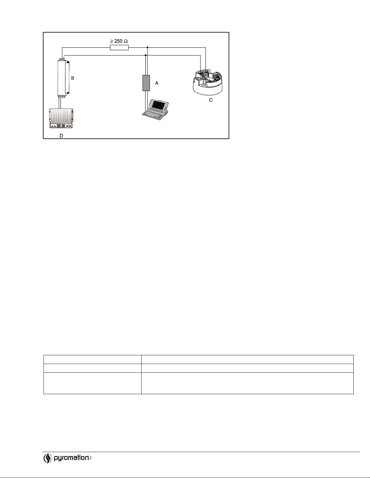
4.3 HART connection
Connection is made directly using the (4 to 20) mA signal cables. Note: The measurement circuit must have a load of at least
250 Ω. See Figure 4-2 and 4-3.
Connection of a HART hand operating module DXR 275
Figure 4-2 Electrical connection of the HART
A = HART
B = Loop power supply
C = HART
module
transmitter
operating module
D = PLC with passive input
2 of 11 Phone (260) 484-2580
• FAX (260) 482-6805 or (800) 837-6805 • www.pyromation.com 442-D
Copyright 2006 Pyromation, Inc., All rights reserved.
Page 3
Underranging
Linear drop from 4.0 to 3.8 mA
Connection of HART modem using TransComm Software
Figure 4-3 Electrical connection of the HART
A = HART
B = Loop power supply
C = HART
modem
transmitter
modem
D = PLC with a passive input
4.4 Shield grounding
Please take note when installing the head transmitter remotely in a field housing. The shield on the (4 to 20) mA signal output must
have the same potential as the shield at the sensor connections! When using grounded thermocouples, shielding of the output (4
to 20) mA cable is recommended. In plants with strong electromagnetic fields, shielding of all cables with a low ohm connection to
the transmitter housing is recommended.
5 OPERATION
5.1 Communication
The temperature transmitter is setup using the HART
using a universal hand operating module “HART
protocol. The values measured can also be read using the HART protocol
Communicator DXR 275/375.
5.2 HART Communicator DXR 275
Selection of the unit functions using the “HART
special HART
Hint: When using the HART
release the HART
HART
function matrix (see figure 6-2).
function matrix by entering 281 in the LOCK function. The condition remains even after a power failure. The
hand unit all parameters can be read out, however, the programming is blocked. It is possible to
function matrix can be locked again by releasing the personal code number. More detailed information to the HART hand
Communicator” is done using various menu levels as well as with the help of a
operation module can be found in its respective operating manual.
6 INSTALLING
6.1 Installation check
Monitor all connections making sure they are tight. In order to guarantee fault free operation the terminal screws must be tight onto
the connection leads. The unit is now ready for operation.
6.2 Function check
Measuring the analog (4 to 20) mA output signal or following failure signals:
Overranging Linear increase from 20.0 to 20.5 mA
Failure, e.g. sensor breakage; sensor
short circuit
6.3 Installation
Once the power supply has been connected the head transmitter is operational.
3 of 11 Phone (260) 484-2580
≤ 3.6 mA (“low”) or ≥ 21 mA (“high”), can be selected
The “high” alarm setting can be set between 21.6 mA and 23 mA, thus providing the
flexibility needed to meet the requirements of various control systems.
Copyright 2006 Pyromation, Inc., All rights reserved.
• FAX (260) 482-6805 or (800) 837-6805 • www.pyromation.com 442-D
Page 4
Sensor
Pt100 (RTD)
6.4 Quick Setup
The head transmitter left the factory with a default parameter configuration. If no customer specific configuration was mentioned on
the order then the default parameter configuration is constructed as follows:
Connection mode 3-wire
Measurement range and units (0 to 100) °C
Using the Quick Setup the operator is led through all the most important unit functions that must be setup for standard
measurement operation of the unit. Using the HART hand module a quick set-up of the black highlighted fields of the HART
function matrix (see figure 6-2) is possible.
• Type of sensor (V2H0)
• Unit meas. Value (V2H2)
• Value of 4 mA (V2H4)
• Value of 20 mA (V2H5)
• Connection (V2H6)
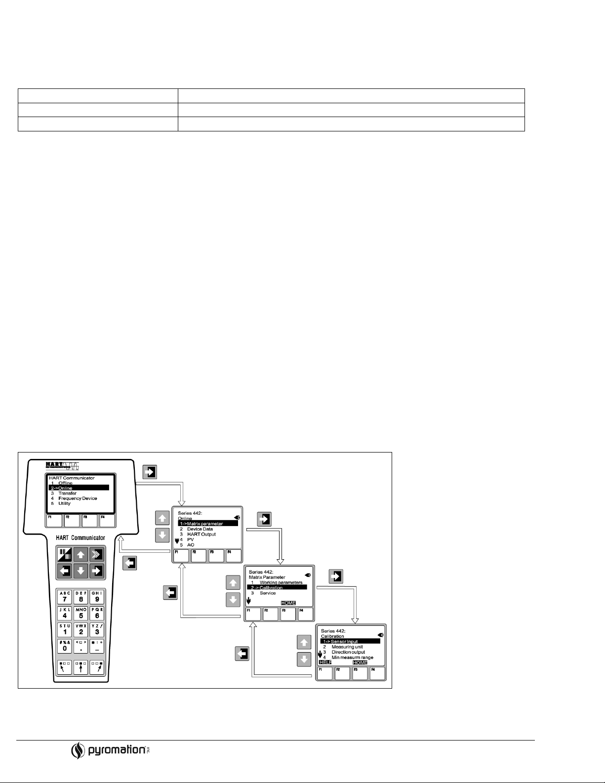
6.5 Configuration with HART protocol
Selection of all head transmitter functions using the HART hand module is done with various menu levels with the help of the
Pyromation function matrix (see figure 6-2). All head transmitter functions are described in 6.6, Description of unit functions.
What needs to be done:
1. Switch on the hand module:
- Measurement unit is not yet connected. The HART
main menu appears. This menu level appears for all HART
programming independent of the type of instrumentation. Information to offline programming can be found in the
“Communicator DXR 275/375 operating manual.
- Measuring unit is connected. The menu level “Online” appears. In this “Online” menu level the actual measured data such
as measured value (PV) and output current (AO) are continuously displayed. Entry into the Series 442 operating matrix is
done using the line “Matrix parameters”. This matrix systematically contains all HART
accessible functions.
2. Using “Matrix parameters” the function group can be selected (e.g. basic calibration) and then followed by the required
function, e.g. “Sensor input”.
3. Enter numeric values or change settings. Then acknowledge using the F4 “Entry” function key.
4. “SEND” appears when operating the F2 function key. Once the F2 key has been operated all values entered in the hand
module are transmitted to the Series 442 measurement system.
5. A return to the “Online” menu level is made using the F3 “HOME” function key. Here, the actual transmitter values measured
with the new settings can be read.
Figure 6-1 Configuration at the hand module example “Sensor input”
4 of 11 Phone (260) 484-2580
• FAX (260) 482-6805 or (800) 837-6805 • www.pyromation.com 442-D
Copyright 2006 Pyromation, Inc., All rights reserved.
Page 5

Figure 6-2 HART function matrix
Function group: WORKING PARAMETERS
6.6 Description of unit functions
The following table contains a listing and description of all functions of the HART protocol that can be used for setting up the
temperature transmitter. Note: Factory default values are shown in bold text. The HART operating module (DXR275) display is
indicated by the following symbol.
Primary value
• V0H0
• (PV)
Int. temperature
• V0H1
Filter time
• V0H2
RJ Mode
• V0H3
RJ External Value
• V0H4
Display of actual measured temperature
Display: 7-digit number with floating decimal point and engineering unit.
(e.g. 199.98 Ohm; -62.36 deg. C)
Display of the actual measured temperature of the internal comparison measurement point.
Digital filter selection 1st grade.
Input: (0 to 100) seconds
0 s
Selection of internal (Pt100) or external (0 to 80) °C cold junction compensation.
Entry: Internal; External
Internal
Entry of external cold junction value.
Entry: (-40.00 to 85.00) °C (°C, °F, K)
0.00 °C
Hint! Entry only possible on selection of an external cold junction compensation in unit function
RJ MODE.
Bias Input (Offset)
• V0H5
Entry of zero point correction (Offset).
Entry: (-10.00 to 10.00) °C (°C, °F, K)
0.00 °C
Hint! Entry returns to factory default values when changing sensor type!
5 of 11 Phone (260) 484-2580
• FAX (260) 482-6805 or (800) 837-6805 • www.pyromation.com 442-D
Copyright 2006 Pyromation, Inc., All rights reserved.
Page 6

Function group: BASIC CALIBRATION
Type of sensor
°
• V2H0
Entry of sensor used:
Sensor type Range start Range end value
(-10 to 75) mV -10 mV 75 mV
(10 to 400) Ω 10 Ω 400 Ω
(10 to 2000) Ω 10 Ω 2000 Ω
Pt100 DIN -200 °C [-328 °F] 850 °C [1562 °F]
Pt100 JIS -200 °C [-328 °F] 649 °C [482 °F]
Pt500 -200 °C [-328 °F] 250 °C [482 °F]
Pt1000 -200 °C [-328 °F] 250 °C [482 °F]
Ni100 -60 °C [-76 °F] 180 °C [356 °F]
Ni500 -60 °C [-76 °F] 150 °C [302 °F]
Ni1000 -60 °C [-76 °F] 150 °C [302 °F]
Polynom RTD -270 °C [-454 °F] 2500 °C [4532 °F]
Type B 0 °C [32 °F] 1820 °C [3308 °F]
Type C 0 °C [32 °F] 2320 °C [4208 °F]
Type D 0 °C [32 °F] 2495 °C [4523 °F]
Type E -270 °C [-454 °F] 1000 °C [1832 °F]
Type J -210 °C [-346 °F] 1200 °C [2192 °F]
Type K -270 °C [-454 °F] 1372 °C [2501 °F]
Type L -200 °C [-328 °F] 900 °C [1652 °F]
Type N -270 °C [-454 °F] 1300 °C [2372 °F]
Type R -50 °C [-58 °F] 1768 °C [3214 °F]
Type S -50 °C [-58 °F] 1768 °C [3214 °F]
Type T -270 °C [-454 °F] 400 °C [752 °F]
Type U -200 °C [-328 °F] 600 °C [1112 °F]
Polynom TC -270 °C [-454 °F] 2500 °C [4532 °F]
Pt100 DIN
Temp. Compensation
• V2H1
Measuring Unit
• V2H2
Current output
• V2H3
Value of 4 mA
• V2H4
Value of 20 mA
• V2H5
Connection
• V2H6
• RTD connection
Selection of temperature compensation of the cold junction when using customer specific
linearization of the TC polynomial
Input:
None, Type B, Type C, Type D, Type E, Type J, Type K, Type L, Type N, Type R, Type S, Type T,
Type U
None
Enter engineering units.
Entry: °C, °F, K
C
Enter standard (4 to 20) mA or inverse (20 to 4) mA current output signal.
Entry: 4-20 mA
20-4 mA
4-20 mA
Entry: For limits see unit function SENSOR TYPE
0.00 °C
Entry: For limits see unit function SENSOR TYPE.
100.00 °C
Entry of RTD Connection mode
Entry: 2 wire
3 wire
4 wire
3 wire
6 of 11 Phone (260) 484-2580
Copyright 2006 Pyromation, Inc., All rights reserved.
• FAX (260) 482-6805 or (800) 837-6805 • www.pyromation.com 442-D
Page 7

Function group: USER LINERIZATION
The following function fields are only active in the unit function SENSORTYPE (V2H0) on selection of customer-specific linearization (Polynomial TC or RTD)
Function group: SERVICE
2 wire comp.
• V2H7
Entry of leadwire compensation on RTD 2 wire connection
Entry: (0.00 to 30.00) Ohm
0.00 Ohm
Failsafe mode
• V2H8
Coefficient X0
• V3H0
Coefficient X1
• V3H1
Coefficient X2
• V3H2
Coefficient X3
• V3H3
Coefficient X4
• V3H4
Entry of failure signal on sensor fracture or short circuit.
Entry: Max (≥ 21.0 mA)
Min (≤ 3.6 mA)
Min
Input of first coefficient for customer-specific linearization (4 th order polynomial with five
coefficients), see 6.8, Interactive setting up of the temperature transmitter
Input COEFFICIENT X1, see 6.8, Interactive setting up of the temperature transmitter
Input COEFFICIENT X2, see 6.8, Interactive setting up of the temperature transmitter
Input COEFFICIENT X3, see 6.8, Interactive setting up of the temperature transmitter
Input COEFFICIENT X4, see 6.8, Interactive setting up of the temperature transmitter
Error code
• V9H0
Last diagnostic
• V9H1
Config. changed
• V9H2
Min Indication
• V9H3
Max Indication
• V9H4
Display of actual error code.
Display: See “8.1, Applicat ion f ault me ssa ges”
0
Display of previous error code.
Display: See “8.1, Application fault messages”
0
Parameter changes are done.
Display: Yes/no
No
Display the minimum process value. The process value is accepted at the beginning of the
measurement.
Hint! Min. process value will be changed to the actual process value on write. On reset to factory
default, the default value is entered.
+10 000
Display the maximum process value. The process value is accepted at the beginning of the
measurement.
Hint! Max. process value will be changed to the actual process value on write. On reset to factory
default, the default value is entered.
-10 000
7 of 11 Phone (260) 484-2580
• FAX (260) 482-6805 or (800) 837-6805 • www.pyromation.com 442-D
Copyright 2006 Pyromation, Inc., All rights reserved.
Page 8

Function group: USER INFORMATION
Default values
• V9H5
Output current
• V9H6
Simulation mode
• V9H7
Simulation value
• V9H8
Security locking
• V9H9
Tag number
• VAH0
Entry: 182 (Reset to factory default settings)
0
Display of the actual output current signal.
Entry of simulation mode.
Entry: Off
On
Off
Entry of simulation value (current).
Entry: (3.58 to 21.7) mA
0.00 mA
Release code for setting up.
Entry: Lock = 0
Release = 281
281
Entry and display of measure point description (TAG).
Entry: 8 characters
Descriptor
• VAH1
Hardware version
• VAH2
Software version
• VAH3
• Software Rev.
Serial Number
• VAH4
Entry and display of plant description.
Entry: 16 characters
Display of unit version.
e.g.: 1.0000 indicates version 1.00.00
Display of software version.
e.g.: 8010 indicates version 1.0
8-digit display of Pyromation device serial numbers
8 of 11 Phone (260) 484-2580
Copyright 2006 Pyromation, Inc., All rights reserved.
• FAX (260) 482-6805 or (800) 837-6805 • www.pyromation.com 442-D
Page 9

Configurable parameters
Fault code
Cause
Action/cure
106
201
6.7 Configuration using HART
The configuration of the head transmitter can be done using both the HART
table shows the structure of the interactive menu led operation of TransComm.
protocol and TransComm
protocol and the TransComm software. The following
• Sensor type
• Connection mode (2, 3 or 4 wire connection)
• Units (°C or °F)
Standard settings
• Measurement range start (depends on sensor)
• Measurement range end (depends on sensor)
• Coefficient X0 to X4 (on sensor type Polynom RTD/TC)
• Temperature-compensation (on sensor type Polynom TC)
• Cold junction compensation (internal/external on TC connection)
• Temperature external (on TC with cold junction compensation external)
• Compensation resistance (0 to 20) Ω on 2 wire connection
• Fault condition reaction (≤ 3.6 mA or ≥ 21.0 mA)
Expanded settings
• Output (analog standard/inverse)
• Damping (0 to 8) s
• Offset (-9.9 to +9.9) °C [-17.8 to +17.8] °F
• TAG (Measurement point identification)
• Identifier (Descriptor)
Service functions
• Simulation (on/off)
For detailed TransComm operating instructions please read the online documentation contained in the software.
6.8 Interactive setting up of the temperature transmitter
Customer specific linearization and sensor matching is done using the TransComm configuration software. The program
calculates the linearization coefficients X0 to X4 that need to be entered into the PC configuration software.
7 MAINTENANCE
The head transmitter is maintenance free.
8 TROUBLESHOOTING
Always start troubleshooting with the checklists below if faults occur after start up or during operation. This takes you directly (via
various queries) to the cause of the problem and the appropriate remedial measures. Note: Due to its design, the device cannot
be repaired. However, it is possible to send the device in for examination.
8.1 Application fault message
Application fault messages are shown in the display of the HART
“ERROR CODE” has been selected.
0
10
11
12
13
14
No fault, Warning None
Hardware fault (unit defective) Replace head transmitter
Sensor short circuit Check sensor
Sensor cable open circuit Check sensor
Reference measurement point defective None
Unit not calibrated Return head transmitter to manufacturer
hand operating module “DXR275/375” once the menu point
Up/Download active None (will be automatically acknowledged)
Warning: Measured value too small Enter other values for measured value range start
202
203
Warning: Measured value too large Enter other values for measured range end
Unit is reset (to factory default settings) None
Copyright 2006 Pyromation, Inc., All rights reserved.
9 of 11 Phone (260) 484-2580
• FAX (260) 482-6805 or (800) 837-6805 • www.pyromation.com 442-D
Page 10

Problem
Possible cause
Remedy
No contact between connecting cables and
correct if necessary.
HART-Modem is connected incorrectly.
Connect HART-Modem correctly.
Problem
Possible cause
Remedy
Observe the face-to-face length of the
sensor.
Device programming is incorrect (number of
wires).
Change the Connection type device
function.
Device programming is incorrect (scal ing) .
Change scaling.
Incorrect RTD configured.
Change the Sensor type device function.
Check that the sensor is connected
correctly.
The cable resistance of the sensor (2-wire)
was not compensated.
Offset incorrectly set.
Check offset.
Connect the connecting cables correctly
(terminal diagram).
Incorrect sensor type set in the Sensor type
device function. Set the correct sensor type.
8.2 Application faults without messages
General errors
Supply voltage does not match that
Device not reacting
specified on the nameplate.
terminals.
Output current < 3.6 mA
HART communication not
working.
Signal cable is wired incorrectly. Check wiring.
Electronics are defective. Replace the device.
Missing or incorrectly installed
communication resistor.
Application errors for RTD sensor connection
Incorrect sensor orientation. Install the sensor correctly.
Heat conducted by sensor.
Measured value is
incorrect/inaccurate.
Sensor connection.
Apply the correct voltage.
Check the contacting of the cables and
Install the communication resistor (250 Ω)
correctly.
Compensate the cable resistance.
Failure current (≤ 3.6 mA or
≥ 21 mA)
Faulty sensor.
RTD connected incorrectly.
Incorrect device programming (e.g. numb er
of wires).
Incorrect programming.
Check the sensor.
Change the Connection type device
function.
10 of 11 Phone (260) 484-2580
Copyright 2006 Pyromation, Inc., All rights reserved.
• FAX (260) 482-6805 or (800) 837-6805 • www.pyromation.com 442-D
Page 11

Problem
Possible Cause
Remedy
Incorrect sensor orientation.
Install the sensor correctly.
Heat conducted by sensor.
Observe face-to-face length of the sensor.
Device programming is incorrect (scaling).
Change scaling.
Incorrect thermocouple type (TC)
configured.
Interference via the thermocouple wire
voltage coupling).
Connect the connecting cables correctly
(terminal diagram).
Incorrect sensor type set in the Sensor type
device function. Set the correct sensor type.
Application errors for TC sensor connection
Measured value is
incorrect/inaccurate
Failure current (≤ 3.6 mA or
≥ 21 mA)
Change the Sensor type device function.
Incorrect comparison measuri ng point set. Set the correct reference junction.
welded in the thermowell (interference
Use a sensor where the thermocouple wire
is not welded.
Offset incorrectly set. Check offset.
Faulty sensor. Check the sensor.
Sensor is connected incorrectly.
Incorrect programming
11 of 11 Phone (260) 484-2580
Copyright 2006 Pyromation, Inc., All rights reserved.
• FAX (260) 482-6805 or (800) 837-6805 • www.pyromation.com 442-D
 Loading...