

Page 1
1990
SI
PyroMATION,
INSTRUCTION MANUAL
Series 423 Digital Indicator
®
INC.
Copyright© 1993, Pyromation, Inc.
(01/94)
Page 2

TABLE OF CONTENTS PAGE
NO.
1-1
2-1
2-2
3-1
4-1
5-1
5-2
5-3
5-4
6-1
6-2
6-3
7-1
7-2
7-3
7-4
Notes .....................................................................................................................
General Information..........................................................................................
Limited Warranty...............................................................................................
Specifications......................................................................................................
Thermocouple and RTD Order Code.................................................................
Unpacking..........................................................................................................
Location.............................................................................................................
Mounting..............................................................................................................
Mounting Illustrations............................................................................................
Line Supply Wiring............................................................................................
AC Line Conversion............................................................................................
RTD Input Wiring...............................................................................................
Thermocouple Input Wiring...............................................................................
Relay Wiring.........................................................................................................
Auxillary Power Supply Wiring.........................................................................
4 - 20mA Input with and without Loop Power ..................................................
1
2
2
3
4
5
5
5
5
6
6
6
7
7
7
7
8-1
8-3
9-1
10-1
11-1
12-1
13-1
14-1
14-2
15-1
16-1
17-1
12 - Position Selector Switch Wiring Illustrations............................................
Unit Repairs........................................................................................................
Trouble Shooting.................................................................................................
Main Menu Program...............................................................................................
Relay Menu Program............................................................................................
4 - 20mA Menu Program.....................................................................................
4 - 20mA Calibration Procedures..........................................................................
Password Menu Program......................................................................................
Calibration Menu Program..................................................................................
Calibration Procedures..........................................................................................
RTD Calibration Procedures............................................................................
CJC Calibration Procedures................................................................................
8
8
9
10
11
12
13
14
14
15
16
17
Page 3

2-1 GENERAL INFORMATION
The 423 Series Instruments are a Microprocessor-Based Digital Process Indicator for thermocouples and RTD's. The instrument
has no potentiometers for calibration. All calibration is done from the
front panel and stored in non-volatile memory. The program menu has
been secured at the factory by the use of a password which prevents
unauthorized users from entering the calibration mode.
Thermocouple and RTD inputs can be changed through the
pushbuttons as well. Calibration for these are also prompted through
pushbutton commands. Again, there are no potentiometers for calibration. Fahrenheit and Celsius and decimal point conversions are made
through menu commands.
Menu program lockout is available through pushbutton commands. This lockout is a specified codeword which prevents personnel
from entering the menu if desired. There is a universal codeword which
will over-ride any user specified codeword. This is maintained in case
the user loses or forgets the specified codeword.
2-2 LIMITED WARRANTY
THE MODEL 423 SERIES DIGITAL INDICATOR SOLD BY OR PURCHASED FROM PYROMATION, INC. OR
FROM AN AUTHORIZED PYROMATION DISTRIBUTOR, OR AGENT IS SUBJECT TO THE FOLLOWING
LIMITED WARRANTY.
This product is warranted to be free from functional defects in materials and workmanship at the time the product
leaves the Pyromation, Inc. factory, and to conform at that same time to the specifications set forth in the relevant
Pyromation, Inc. installation, wiring, operation manual for this product for a period of one year after shipment from the
Pyromation, Inc. factory.
Pyromation's exclusive and sole obligation, and Buyer's exclusive and sole remedy under the above Limited Warranty
is limited to either repair or replacement of such product, at Pyromation's option, free of charge to Buyer. Pyromation
shall have no obligation to repair or replace unless the claimed defect in material or workmanship is reported in writing
to Pyromation at 5211 Industrial Road, Fort Wayne, Indiana 46825 within ten (10) days after delivery to the Buyer from
Pyromation or an authorized Pyromation distributor, representative or reseller. If so requested by Pyromation, the
product shall be returned to a designated facility during normal business hours, transportation prepaid.
Any action for breach of this warranty or other action arising out of this contract must be commenced within one year
after delivery.
Pyromation shall not be liable for any warranty, express or implied, other than the warranty stated above, and in the
event of a breach of the above stated warranty, Pyromation shall not be liable for any incidental, consequential, special,
or other damages, costs, or expenses other than repair or replacement as described above. Pyromation excludes
any and all warranties of merchantability or fitness for a particular purpose. The above stated warranty extends only
to the original Buyer from Pyromation, Inc. or from an authorized Pyromation distributor or agent, and may not be
transferred or assigned.
Page 2
Page 4

3-1 SPECIFICATIONS
- STANDARD -
Power Supply:
DC Isolation:
Ambient Temperature:
Overall Accuracy:
Input Impedance:
RTD Excitation Current:
Error Due to Lead Resistance:
Conversion Rate:
Filtering:
Resolution:
120 or 240VAC +10%/-15%
50/60HZ
External Fuse Required - .5A
@ 500 VP
32 to 122°F (0 - 50°C)
RTD or Thermocouple: + 1°F
4 - 20 mA: + .1%
47M Ohm (Millivolt inputs only)
.25mA
0.1uV per Ohm (T/C Inputs Only)
2.5 per Second
Digital: Average of 16 conversions per update
Analog: 2.2K in parallel with 0.1uf
.1 or 1 Degree
(Automatic 1 Deg., Resolution above 999.9)
Display:
Display Readouts:
Physical Dimensions:
Power Supply:
Auxillary Power Supply:
Relays:
.54" High LED, High Intensity Alpha Numeric
UNDR - Underrange
OVER - Overrange
OPEN - Open Input
48 x 96 x 148mm (overall dimensions)
(1.89" x 3.78" x 5.83")
- OPTIONS -
12 or 24 VDC +20/-10%
External Fuse Required - .5A
24 VDC (30 mA Maximum)
250 VAC (8A Maximum)
30 VDC (8A maximum)
Page 3
Page 5
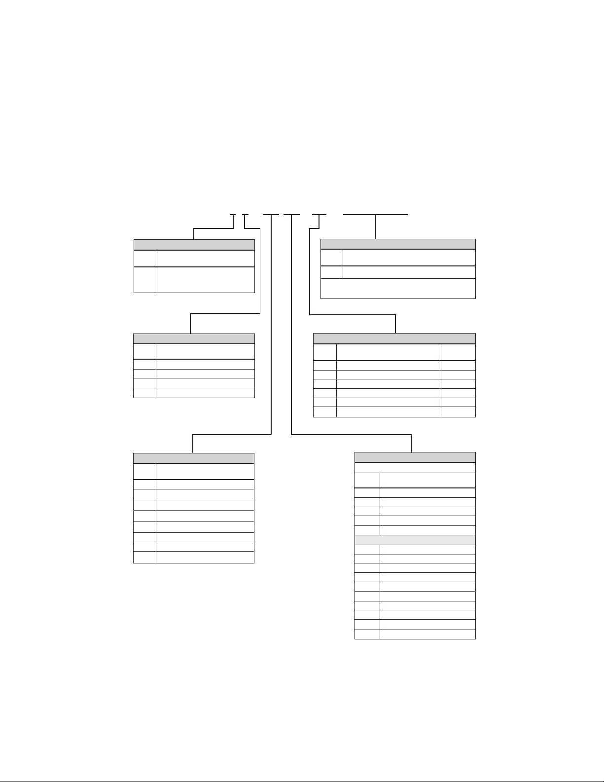
4-1 ORDER CODE
Example Order Number:
- - - -
423 1 1 42 R1 04 S (0-5000)
METER STYLE
ORDER
CODE
1
DESCRIPTION
Input Selectable for T/C or RTD's
with Fixed Range or 4 - 20 mADC
with Scaleable Display
Table 6Table 1
ORDER
CODE
S
* Insert actual scaling desired as per examples below
Table 5Table 2
DISPLAY SCALING
Factory Scaled 4-20 mA Inputs Only
0 - 5000, 50 - 150, -100 to 100, 500-0
POWER SUPPLY OPTIONS
ORDER
CODE
1
2
3
4
Table 3 Table 4
ORDER
CODE
00
85
42
4J
4K
4T
4E
4N
* Meters are shipped calibrated for Type K
thermocouples, degrees F, and 1° resolution
DESCRIPTION
120 VAC
240 VAC
24 VDC
12 VDC
(Field Selectable)
(Field Selectable)
(Factory Installed)
(Factory Installed)
INPUT SELECTION
DESCRIPTION
Customer Configured *
100 Ohm Plat. RTD, .00385 T.C.
4 - 20 mADC
Type
J
Thermocouple
K
Thermocouple
Type
Type T Thermocouple
E
Thermocouple
Type
N
Thermocouple
Type
ORDER
CODE
00
01
02
03
04
05
DESCRIPTION
No Options
Splash Proof Panel Gasket Seal
Meter Mounted 12 Pt. Sel. Switch
One SPDT Process Alarm
SPDT Process Alarms
Two
VDC Power Supply Output
24
ORDER
CODE
00
F1
F2
C1
C2
00
F1
F2
C1
C2
00
R1
R2
R3
R4
DESCRIPTION
AVAIL.
LIMITS
Not w/Opt. 02
DISPLAY RESOLUTION
T/C or RTD INPUTS
DESCRIPTION
Customer Configured
1° F
.1° F
1° C
.1° C
4 to 20 mA INPUTS
Customer Configured
1° F
.1° F
1° C
.1° C
Customer Configured
1
Unit Resolution
.1
Unit Resolution
.01
Unit Resolution
.001
Unit Resolution
*
(9999)
(999.9)
(99.99)
(9.999)
Page 4
Page 6
5-1 UNPACKING
Unpack the instrument immediately upon receipt, and visually
inspect for shipping damages. If the instrument was damaged in
transit, note any damage and file a claim with the carrier.
5-2 LOCATION
Install the instrument in an area where it will not be subjected to
excessive shock, vibration, dirt, oil, and where the temperature will not
exceed 0-50°C (32-122°F). The instrument should not be installed in
an area where rapid temperature changes may occur (e.g. near heating
or cooling ducts).
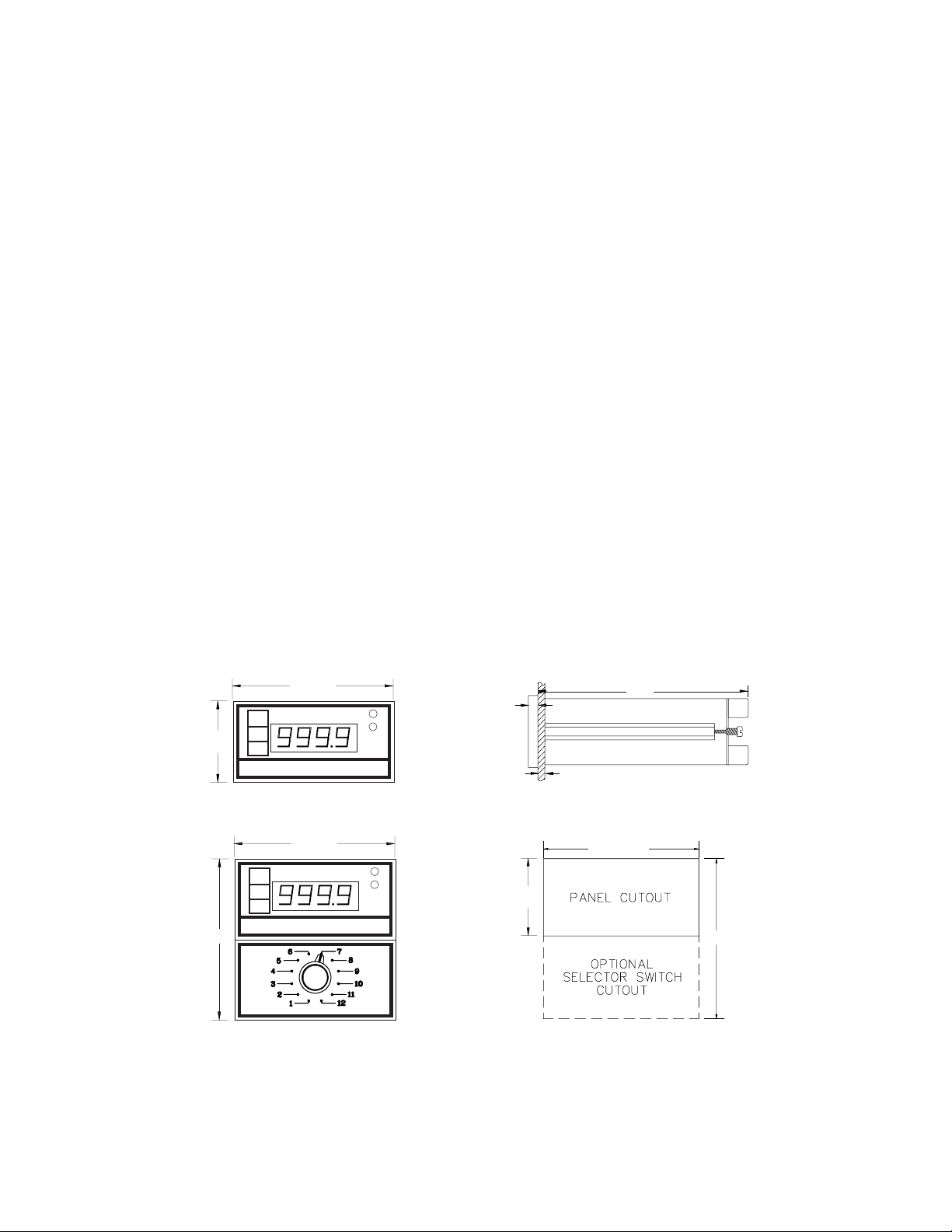
5-3 MOUNTING
Figure 1 thru figure 4 below shows panel cutout dimensions and
case dimensions. (For units with 12 position selector, cutout dimensions are
3.67" high by 3.56" wide).
Remove slide retaining screws and slides.
Insert the instrument through the cutout from the front side of the panel
and re-insert slides and screws. Do not over-tighten screws.
5-4 MOUNTING ILLUSTRATIONS
1.89"
3.78"
Figure 1
s
l
t
PyroMATION, INC.
Figure 3
s
l
t
PyroMATION, INC.
PyroMATION, INC.
3.78"
3.78"
Figure 2
1
2
C
F
.25"
0.0 - .188" THICK
5.58"
Figure 4
3.56" MIN.
1
2
C
F
Page 5
1.77"
MIN.
3.67" MIN.
Page 7

6-1 LINE SUPPLY WIRING
Figure 5 Figure 6
120 or 240 VAC Line Supply
12 or 24 VDC Line Supply
GND
12
.5A FUSE
+
-
D C
SUPPLY
6-2 AC LINE SUPPLY CONVERSION
The 423 Series meter can be field changed from 120 to 240 VAC or back.
This is accomplished by changing the jumper on the PC board. The jumpers are
located in the rear next to the transformer. See figures below. (This change will
not void the limited warranty).
Figure 8Figure 7
Jumpers
Jumper
6-3 RTD INPUT WIRING
Figure 9
3 Wire RTD Hookup
GND
567
Figure 10
2 Wire RTD Hookup
RTD
JUMPER
5
67
NOTE: RTD input extension wire should not be run in the same conduit as line voltage, nor should they be exposed
to excessive electrical noise.
RTD
Figure 11
4 Wire RTD Hookup
NO CONNECTION
RTD
765
Page 6
Page 8

7-1 THERMOCOUPLE INPUT WIRING
Figure 12
GND
Note: Thermocouple input extension wire should not be run in the same conduit as line voltage, nor should they be
exposed to excessive electrical noise. Always use compensated leadwire when wiring for thermocouple inputs.
T/C
-
56
T/C
+
7-2 RELAY WIRING
Figure 13
ALARM 2
8
910 1213 14
GND
ALARM 1
11
* See note on Page 11
7-3 AUXILLARY POWER SUPPLY WIRING
Figure 14
11
+
24 VDC
OUTPUT
-
3
7-4 4 - 20mA INPUT with and without INTERNAL LOOP POWER
Figure 15 -
GND
RTD
RED
RED
with Loop Power
11
+
-
-
43
WHITE
5
JUMPER
+
Page 7
Figure 16 - without Loop Power
GND
4
5
+
RED
RED
RTD
WHITE
-
+
Page 9

8-1 12-POSITION SELECTOR SWITCH WIRING ILLUSTRATIONS
8-2
Figure 17
RTD Selector Switch Connections
65
COPPER
OUTPUT
SWITCH
BOX
WIRE
SWITCH
RTD
7
Figure 19
Figure 18
Thermocouple Selector Switch Connections
6
5
+
-
T/C
WIRE
SWITCH
OUTPUT
SWITCH
BOX
T/C
(RED)
-
T/C
+
.250"
1.06"
Note: Always use compensated leadwire when wiring for thermocouple inputs.
5.58"
8-3 UNIT REPAIRS
If returning instrument, contact the factory or local representa-
tive for a Return Authorization Number. Include the reason for the
return with your shipment.
Page 8
Page 10

9-1 TROUBLE SHOOTING
PROBLEM
' OPEN '
' OVER '
' UNDR '
Erratic Readings
POSSIBLE CAUSES
l
Sensor not connected
l
Damaged sensor
l
Sensor is over temperature range
l
Incorrect sensor
l
Sensor is under temperature range
l
Incorrect sensor
l
Wrong polarity on connection
l
Loose connection on sensor input
l
Damaged sensor
l
AC noise on sensor connections
POSSIBLE WIRING ERRORS
Destructive Errors
l
Do not connect power to the sensor input. This could destroy
the panel meter.
l
Do not connect power to the sensor itself.
l
Incorrect line power on the unit; check options.
Non-Destructive Errors
l
Reversing the polarity on line power input.
l
Reversing the polarity on sensor input.
Page 9
Page 11

10-1 MAIN MENU
Below is a block diagram showing the basic menu program. Specific menu breakdowns
are described on the following pages. The middle button is used as the enter key.
This will move you through the program. The buttons allow you to view and
change variables to the program. Please note, to eliminate changes made, simply
disconnect power before you come to the
ENTER PSWD
This Portion
Not Applicable
If Password Is Off
DISPLAYED
000
TO PASSWORD
028 PASSWORD
MENU
SNSR
PWRD YES/NO prompt.
Figure 20
(028 is Universal Password)
J K T....PRESENT INPUT TYPE
TO SCROLL THROUGH INPUT
or
RETURN WHEN
AT DESIRED INPUT
DP
UNIT
or
or
TO CHANGE DECIMAL
TO CHANGE F / C
RLY 1
or
YES / NO
RLY 2
or
YES / NO
CAL
IF CALIBRATING, SEE FIGURE 24
PWRD
or
YES / NO
WAIT
.
.
V3.1
.
.
PRESENT
DISPLAY
TYPES
IF YES, SEE FIGURE 21
IF NO
IF YES, SEE FIGURE 21
IF NO
IF YES, SEE FIGURE 23
IF NO
Page 10
Page 12

11-1 RELAY MENU
RLY 1
or
RLY 2
or
YES/NO
YES/NO
Figure 21
IF YES
IF NO
IF YES
IF NO
or
or
LOW/HIGH
LOW/HIGH
SP 1
or
SP 2
or
150
150
RETURN WHEN
AT DESIRED
SETPOINT
RETURN WHEN
AT DESIRED
SETPOINT
HYS 1
or
001
RETURN WHEN
AT DESIRED
HYSTERISIS
HYS 2
or
001
RETURN WHEN
AT DESIRED
HYSTERISIS
CAL
.
.
.
Note 1: Recommend using MOVs on Relay Terminals. Metal-oxide varistors (MOVs) are
variable resistors for protecting electronic circuits against AC (alternating-current) voltage
transients.
Note 2: They must be operated within their ratings or they will be destroyed.
Page 11
Page 13

12-1 4 - 20 mA MENU
SNSR
MAMP
DP
or
UNIT
or
ZERO
k
CONNECT 4mA SOURCE
or
TO CHANGE DECIMAL
TO CHANGE F/C/OFF
RETURN WHEN
000
AT DESIRED
READING
Figure 22
WAIT
SPAN
k
CONNECT 20mA SOURCE
or
WAIT
UNDR
or
OVER
or
RLY 1
.
.
.
RETURN WHEN
000
000
000
AT DESIRED
RETURN WHEN
AT DESIRED
UNDER INDICATION
RETURN WHEN
AT DESIRED
OVER INDICATION
Page 12
READING
Page 14

13-1 4 - 20mA CALIBRATION PROCEDURES (All steps must be completed)
{Step 1}
{Step 2}
{Step 3}
{Step 4}
{Step 5}
{Step 6}
= UP
= ENTER
= DOWN
Power panel meter for at least 30 minutes.
Enter menu program, go to the SNSR menu. Press the ENTER
button. MAMP should appear on the display. If not, press the
down button until MAMP is displayed. Press the ENTER
button.
Select proper resolution for the decimal point by pressing the
down button. When proper resolution has been selected
press the ENTER button.
Select proper scale indication by pressing the down button.
If °F or °C is not desired, select OFF. Press the ENTER button.
(Note: If OFF was selected, scale indication stickers have
been supplied for the front display)
Now that ZERO appears, press the down or up button, then
select the desired display reading.
Once the display reading has been established, connect a
4mA source to the input of the meter. Refer to Figure 16 for
proper connections. Press the ENTER button. Wait until
SPAN appears.
{Step 7}
{Step 8}
{Step 9}
{Step 10}
Now that SPAN appears, press the down or up button, then
select the desired display reading.
Once the display reading has been established, connect a
20mA source to the input of the meter. Refer to Figure 16 for
proper connection. Press the ENTER button, WAIT until UNDR
appears.
Now that UNDR appears, press the down or up button, then
select the desired display reading for the under indication.
Press the ENTER button.
Now that OVER appears, press the down or up button, then
select the desired display reading for the over indication.
Press the ENTER button. Calibration is now complete.
Refer to 4 - 20mA menu on page 12 for the above steps (fig. 22)
Page 13
Page 15

14-1 PASSWORD MENU
Described below is the menu for selecting menu passwords.
PWRD
Figure 23
NEW PWRD
WAIT
.
V3.1
.
READING
or
YES / NO
IF YES
ENTR
PWRD
RETURN WHEN
AT DESIRED
PASSWORD
028
TO PICK
NEW VALUE
14-2 CALIBRATION MENU
The calibration routine is for thermocouples and RTD's only. Described below is
the menu program for calibration. Each calibration can be independently done
using the down arrow to scroll to the next routine. Push the up arrow
anywhere to exit the calibration routine.
CAL
HOLD UNTIL METER INDICATES SHRT (approximately 1.5 seconds)
PUSH TO SKIP SHORT
USING COPPER WIRE JUMPER TERMINALS 5,6,7
WAIT
PUSH TO SKIP 50mV
50mV
DISCONNECT JUMPERS
INPUT 50.040mV THROUGH COPPER WIRE TO TERMINALS 5,6
Figure 24
WAIT
PUSH TO SKIP 100 OHMS
100 OHMS
INPUT 100.0W ACROSS TERMINALS 5,6,7
DISCONNECT 50.040mV
WAIT
PUSH TO SKIP CJC
CJC
DISCONNECT 100W
or
PWRD
.
.
TO VIEW
77.0
or
Page 14
Equipment Needed for Calibration
50.040 mV + .005 Power Source
100.03W
+ .01W Resistor
+ .1°F Thermometer
Note1 : Adjust a potentiometer to achieve
100.03W
TO SET NEW VALUE
AGAINST THERMOMETER
1
Page 16

15-1 THERMOCOUPLE CALIBRATION PROCEDURE
{Step 1}
{Step 2}
{Step 3}
{Step 4}
= UP
= ENTER = DOWN
Power panel meter for at least 30 minutes.
Enter menu program, go to the CAL mode. Press the down
button and hold for approximately 1.5 seconds until the meter
reads SHRT, then release the button. Failure to hold the button
for 1.5 seconds will terminate the calibration process.
Install jumpers between terminals 5, 6, and 7 using copper
wire. Press and release the enter button. Wait until 50mV
appears. Disconnect jumpers.
JUMPER
6
5
7
Figure 25
Now that 50mV appears, connect the leads from the 50mV
source to the meter using terminals 5 and 6, remembering that
terminal 5 is negative. Set the voltage supply for 50.040mV,
then press and release the enter button. This simulates a
thermocouple input. Wait until 100 ohm appears. Disconnect
supply.
{Step 5}
{Step 6}
Press the down button to skip 100 ohm input.
Now that CJC appears, place the thermometer across the
terminal strip and do not remove until the temperature stabilizes. The reading from the thermometer is going to be the new
CJC temperature. Press and release the enter button. Use the
up or down button to set the value, then press the enter button
three times until V3.1 appears. Calibration is now complete.
Figure 26
CJC COMPENSATION
Note: If calibration is off due to the CJC, refer to CJC Calibration on page 17
Page 15
Page 17

16-1 RTD CALIBRATION PROCEDURES
{Step 1}
{Step 2}
{Step 3}
{Step 4}
= UP
= ENTER = DOWN
Power panel meter for at least 30 minutes.
Enter menu program, go to the CAL mode. Press the down
button and hold for approximately 1.5 seconds until the meter
reads SHRT, then release the button. Failure to hold the button
for 1.5 seconds will terminate the calibration process.
Install jumpers between terminals 5, 6, and 7 using copper
wire. Press and release the enter button. Wait until 50mV
appears. Disconnect jumpers.
JUMPER
6
5
7
Figure 27
Press the down button to skip 50mV input.
{Step 5}
{Step 6}
Now that 100 ohm appears, install jumper between terminals
6 and 7, and insert the 100W resistor into terminals 5 and 6.
Then press and release the enter button. This simulates a 3
wire RTD. Wait until CJC appears. Disconnect jumper and
resistor.
RTD
5
67
JUMPER
Figure 28
Press the up button to save and exit calibration, then press the
enter button three times until V3.1 appears. Calibration is now
complete.
Page 16
Page 18

17-1 CJC CALIBRATION PROCEDURES
{Step 1}
{Step 2}
{Step 3}
{Step 4}
= UP
= ENTER = DOWN
Power panel meter for at least 30 minutes.
Enter menu program, go to the CAL mode. Press the down
button and hold for approximately 1.5 seconds until the meter
reads SHRT, then release the button. Failure to hold the button
for 1.5 seconds will terminate the calibration process.
Press the down button until CJC appears.
Now that CJC appears, place the thermometer across the
terminal strip and do not remove until the temperature stabilizes. The reading from the thermometer is going to be the new
CJC temperature. Press and release the enter button. Use the
up or down button to set the value, then press the enter button
three times until V3.1 appears. Calibration is now complete.
Figure 29
CJC COMPENSATION
Page 17
 Loading...