

Page 1
OPERATING MANUAL
Thermocouple Thermometer Models
28-02700-J (Type J)
28-02700-K (Type K)
28-02700-T (Type T)
5211 Industrial Road
Fort Wa yne, Indiana U .S.A. 46825
(260) 484-2580
(260) 482-6805 (Fax)
A-1299-0680
Edition 05
Page 2

CERTIFICATE OF
CONFORMANCE
This thermometer was calibrated using
equipment traceable to the National Institute
of Standards and Technology (NIST).
This instrument conforms to
NIST monograph 175 revised to
ITS-90.
The accuracy of the thermometer at the time
of calibration was within specifications stated
in the operating manual.
Model No.:_________________________
Serial Number:______________________
Date placed in service:________________
T o purchase an NIST certificate of traceability
with test data and test date for meter and probe,
please contact your dealer or:
PYROMA TION
5211 Industrial Road
Fort Wa yne, Indiana U. S.A. 46825
260-484-2580
Page 3
INTRODUCTION
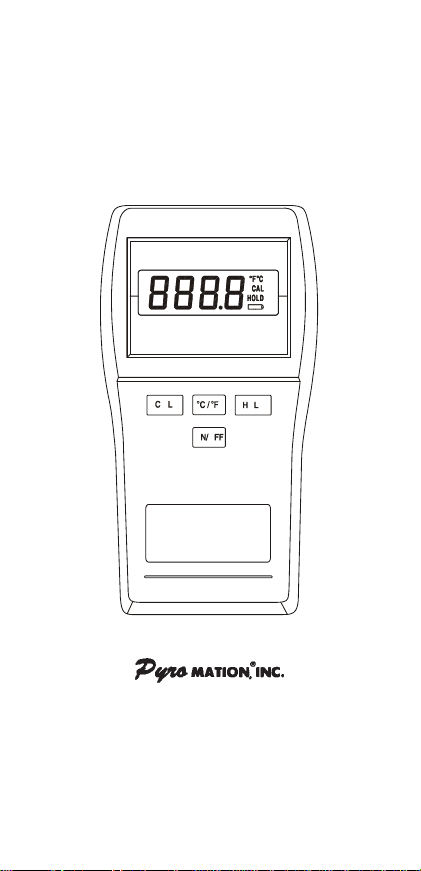
This versatile hand-held instrument provides highly
accurate temperature measurements. The instrument is designed for easy operation and includes
the following features:
• Operator selection of Celsius or Fahrenheit scale
• Resolution of 0.1° from –99.9 to 299.9°
• Four-digit LCD
• Hold feature for temporarily retaining a reading
• Field calibration capability
• Low battery warning
• Built-in tilt stand for easy hands-free operation
• T wo blade f emale ANSI mini-connector input
• Operates with a wide selection of probes
1
Page 4
SAFETY PRECAUTIONS
WARNING
LOW LEVEL SIGNALS SUPPLIED BY STANDARD THERMOCOUPLES. UNDER NO CIRCUMSTANCES SHOULD THE INPUT V OLT A GE
EXCEED THE SPECIFIED 50V RMS.
CAUTION
MICROWAVE OVENS OR ANY ABNORMALLY
HOT OR COLD AREAS.
CAUTION
STRUMENT . DEAD BATTERIES CAN LEAK AND
CAUSE D AMAGE T O UNIT.
DANGER
ALSO BE PRESENT AT THE BATTERY TERMINALS. ALWAYS DISCONNECT THE THERMOCOUPLE WHEN CHANGING BATTERIES.
WARNING
PHERE, BA TTERIES MUST ONLY BE CHANGED
IN AN AREA KNOWN TO BE NON-HAZARDOUS.
A VERTISSEMENT
D'ATMOSPHERES DANGEREUSES, NE
CHANGER LES BATTERIES QUE DANS DES
EMPLACEMENTS DESIGNES NON DANGEREUX.
WARNING
PHERE BY ELECTROSTATIC DISCHARGE,
CLEAN WITH DAMP CLOTH.
THIS INSTRUMENT IS
DESIGNED TO ACCEPT
DO NOT USE OR STORE
THIS INSTRUMENT IN
WEAK BA TTERIES SHOULD
NOT BE LEFT IN THE IN-
VOLTAGES PRESENT AT
THE THERMOCOUPLE MAY
TO PREVENT IGNITION OF
A HAZARDOUS ATMOS-
AFIN DE PREVENIR
L'INFLAMMATION
TO PREVENT IGNITION OF
A HAZARDOUS ATMOS-
2
Page 5

SPECIFICATIONS
THERMOCOUPLE PROBES
Typ e Temperature Range
T ype J: –200°C to 1000°C (–328°F to 1832°F )
T ype K: –250°C to 1372°C (–418°F to 2501°F )
T ype T: –250°C to 400°C (–418°F to 752°F )
Out of range display: - - - Resolution: 0.1°/1° autoranging, 0.1° from
–99.9° to 299.9°, 1° outside this range.
Accuracy
> –99.9°: +(0.2% of reading +0.5°C)
< –99.9°: +(0.25% of reading, +1°C)
Display: 4-digit LCD with 0.5 in high numerals.
Display update rate: 0.6 sec per update.
Input: One thermocouple with ANSI connector.
Input Protection: 50V rms
Battery: Two AA, 1.5V alkaline ANSI-L40,
IEC-LR6.
Battery Life: 750 hours continuous, typical.
Low battery indication
Battery Symbol on when 8 to 10 hours of
battery life remains.
Battery symbol blinking: replace battery
Operating Conditions
Stated accuracy: 18°C to 28°C (64°F to 82°F)
Useful range: 0°C to 40°C (32°F to 104°F)
Storage: –40°C to 65°C (–40°F to 149°F)
Humidity (non-condensing): 10% to 90%
+(0.2% of reading +0.9°F)
+(0.25% of reading +2°F)
3
Page 6

Dimensions
3 cm D x 8.4 cm W x 15.8 cm H
(1.2 in x 3.3 in x 6.2 in)
Weight with batteries: 227 g rams (8 ounces)
Ingress protection: Meets IEC-529 IP-54 for dust
and water-resistant enclosures.
Intrinsic safety
This product is energy limited for intrinsically safe
operation in hydrogen atmospheres per Class I,
Division 1, Groups A, B, C and D hazardous
(classified) locations for UL per UL913 and CSA
per C22.2 No. 0-M1982 and No. 157-M1987.
Maximum surface temperature: 135°C (T4); UL
file No. E182612 (1997).
Compliance: (For CE Mark)
EN61326-1/A1: 1998 (EU EMC Directive)
4
Page 7

BATTERY INSTALLATION AND
REPLACEMENT
CAUTION
INSTRUMENT. DEAD BATTERIES CAN LEAK
AND CAUSE D AMAGE TO UNIT .
DANGER
ALSO BE PRESENT AT THE BATTERY TERMINALS. ALWAYS DISCONNECT THE THERMOCOUPLE WHEN CHANGING BATTERIES.
WARNING
PHERE, BA TTERIES MUST ONLY BE CHANGED
IN AN AREA KNOWN TO BE NON-HAZARDOUS.
AVERTISSEMENT
D'ATMOSPHERES DANGEREUSES, NE
CHANGER LES BATTERIES QUE DANS DES
EMPLACEMENTS DESIGNES NON DANGEREUX.
WEAK BA TTERIES SHOULD
NOT BE LEFT IN THE
VOLTAGES PRESENT AT
THE THERMOCOUPLE MAY
TO PREVENT IGNITION OF
A HAZARDOUS ATMOS-
AFIN DE PREVENIR
L'INFLAMMATION
5
Page 8

If battery indicator turns on, battery life is appro ximately 8 to 10 hours. The battery indicator will start
blinking with less than 1 hour of life remaining.
AT THIS POINT, BA TTER Y MUST BE CHANGED.
IF BATTERY VOLTAGE GOES TOO LOW, DISPLA Y WILL GO BLANK.
See SPECIFICA TIONS for battery type.
1. Before changing battery , turn instrument off and
disconnect thermocouple.
2. Loosen screw and lift battery cover off back of
case.
3. Remove the two AA batteries.
4. Insert two new batteries observing polarity.
5. Install cover and tighten screw.
6
Page 9

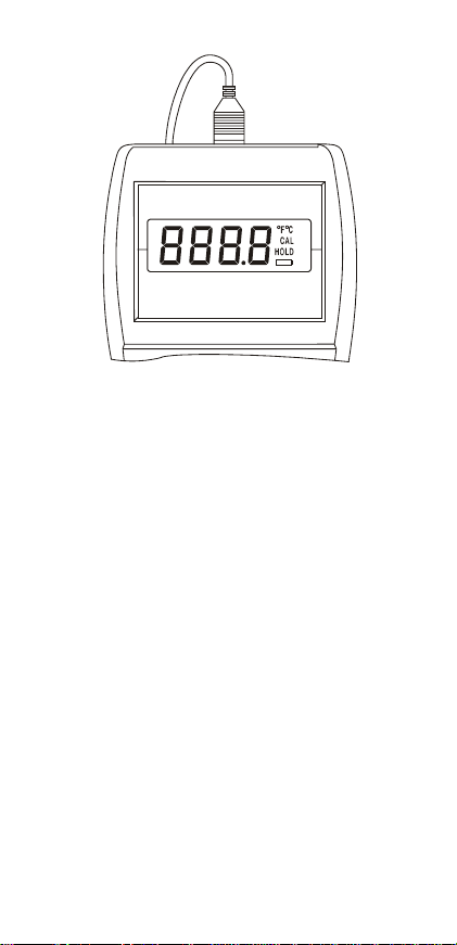
CONNECTING A THERMOCOUPLE
Use the correct thermocouple type for your instrument. Using an incorrect thermocouple type will
result in erroneous readings. Thermocouples are
color coded by type using the North American ANSI
Color Code as follows:
TYPE COLOR
J Black
K Yellow
T Blue
Thermocouple connectors have one wide blade and
one narrow blade.
wards.
Connect thermocouple to receptacle at top
of instrument as shown in the following illustration.
Thermocouple wiring polarity must be correct. If
readings decrease as the temperature increases,
the thermocouple wires may be reversed. The red
wire is negative for thermocouple wires manufactured in North America.
Do not force connector in back-
7
Page 10

8910
Page 11

Page 12

OPERA TION
Note: Be sure the thermocouple you are using
matches the instrument setting indicated on the
unit.
1. Press the ON/OFF key. The thermometer performs a self-test and all display digits and indicators, as shown below, should remain on for
approximately two seconds.
2. If a thermocouple is not connected or if the thermocouple is defective, the display will indicate
OPEn.
3. Select °C or °F by pressing the °C/°F key . Temperature scale can be switched at any time. The
thermometer remembers the last selected scale
the next time you turn the power on.
4. For optimum instrument accuracy, allow one
minute for ambient temperature stabilization. If
the unit has been stored at an extreme ambient
condition, more time will be needed.
Thermocouples are sensitive at the tip or measuring junction. When taking temperature measurements, allow time for the reading to stabilize . Multiplying the time constant of the probe by 5 will give
you the approximate time required.
Note that the readings will automatically change to
1° resolution below –99.9° or above 299.9°.
If desired, press the HOLD key to retain the reading on the display . Press HOLD key again for normal operation.
If the display shows "- - - -" the temperature reading is out of range of the instrument.
Page 13

FIELD CALIBRATION
The thermometer is factory calibrated and does not
require calibration before use. The CAL function
allows single point calibration of the thermometer,
at 0°C (32°F) to compensate for thermocouple offset error. It is not necessary to perform a field calibration to obtain specified meter accuracy . Use the
field calibration feature to improve thermometer/
probe accuracy or to compensate for thermocouple
drift.
1. Follow steps 1 through 4 in OPERATION section.
2. Pack sensing end of probe in a container tightly
packed with crushed ice and filled with distilled
water. Allow temperature to stabilize.
3. Press and hold the CAL key for 5 seconds to
enter the calibration mode, the CAL annunciator
on the display starts blinking. Release the CAL
key .
4. If the measured temperature is from −10°C to
10°C (14 to 50°F), when the temperature reading is stable, press the CAL key .
The CAL indicator will stop blinking and the reading will be set to 0°C (32°F). The CAL indicator
will remain turned on, indicating a field calibration is active.
If “Err” is displayed, either the displa yed reading is
outside the above limits or the batteries are weak.
CANCELING A FIELD CALIBRA TION
1. Turn the thermometer off.
2. Hold the CAL key down while pressing the
ON/OFF key.
The field calibration is canceled and the thermometer reverts to the default factory calibration. The
CAL annunciator is now turned off.
11
Page 14

FIELD CALIBRATION LOCK OUT
AND RE-ENABLE
The calibration lockout feature, pre v ents any field
calibration changes. The loc kout remains in effect
until a lockout re-enable has been performed. Use
the following procedures to lockout or re-enab le the
field calibration operation.
Lockout Procedure
1. Turn the thermometer off.
2. Simultaneously press and hold the CAL and the
°C/°F keys down and momentarily press the ON/
OFF key. Continue to hold the CAL and °C/°F
keys for at least 5 seconds.
Re-Enable Procedure
1. Turn the thermometer off.
2. Simultaneously press and hold the HOLD and
the CAL keys do wn and momentarily press the
ON/OFF key. Continue to hold the HOLD and
CAL keys until the display b lanks.
12
Page 15

MAINTENANCE
Properly used, the thermometer should maintain
calibration indefinitely and not require service other
than occasional cleaning of the housing and changing of the batteries.
CLEANING
WARNING
SPHERE BY ELECTROSTATIC DISCHARGE,
CLEAN WITH DAMP CLOTH.
Do not clean with abrasives or solvents. Use mild
detergents, never immerse nor use e xcessive fluid.
BA TTERIES
If there is no display when the thermometer is
turned on, check condition of the two AA batteries.
Also check that the battery terminals are clean and
batteries are properly installed. If replacement is
necessary, ref er to the BA TTER Y INSTALLA TION
AND REPLACEMENT section for replacement
procedure.
TO PREVENT IGNITION OF
A HAZARDOUS ATMO-
13
Page 16

SERVICE
WARNING
SUBSTITUTION OF COMPONENTS MAY IMPAIR
INTRINSIC SAFETY .
A VERTISSEMENT
LA SUBSTITUTION DE
COMPOSANTS PEUT COM-
PROMETTRE LA SECURITE INTRINSEQUE.
There are no internal adjustments or user
replaceable parts.
If “Err” followed by the numbers 1 through 9 is
displayed (see example below) retur n unit for
service. Note that “Err” alone ma y be displa yed
during improper field calibration.
Note: Serial number label is located inside
battery compartment.
14
A-1925-32
Rev. E
Printed in U.S.A.
050798
Page 17

15
Page 18

WARRANTY
The Manufacturer warrants this product to be free
from significant deviations from published specifications. If repair or adjustment is necessary within
the warranty period, the problem will be corrected
at no charge if it is not due to misuse or abuse on
your part as determined by the Manufacturer. Repair costs outside the warranty period, or those
resulting from product misuse or abuse, may be
invoiced to you.
The warranty period for this product is noted
on the W arranty Card.
PRODUCT RETURN
To limit charges and delays, contact the seller or
Manufacturer for authorization and shipping instructions before returning the product, either within or
outside of the warranty period. When returning the
product, please state the reason for the return. F or
your protection, pack the product carefully and insure it against possible damage or loss. Any damages resulting from improper packaging are your
responsibility .
TECHNICAL ASSISTANCE
If you have any questions about the use of this product, contact the Manufacturer or authorized seller.
Trademarks bearing the ® symbol in this publication are
registered in the U.S. and in other countries.
A-3477-57
Rev. E
Printed in U.S.A.
051000
 Loading...