

Page 1
KITCHEN KNIGHT II RESTAURANT
FIRE SUPPRESSION SYSTEM
(PCL-160/300/460/600)
DESIGN, INSTALLATION, RECHARGE, AND MAINTENANCE MANUAL
TECHNICAL MANUAL
•Components
•Design
•installation
•maintenanCe
•ReCHaRge
One Stanton Street / Marinette, WI 54143-2542, USA / +1-715-735-7411 / www.pyrochem.com
Copyright © 2014 Tyco Fire Products LP. / All rights reserved. / Part No. 551274-06
Page 2

Page 3
US / INTERNATIONAL
®
Tyco Safety Products
One Stanton Street
Marinette, WI 54143-2542
800-526-1079
715-732-3465
BULLETIN
CANADA
Tyco Safety Products
871 Equestrian Court Unit 1A,
2nd Floor
Oakville, ON L6L 6L7 Canada
877-992-6785
905-847-0217
Bulletin Number: 2320
Date: July 8, 2008
TO: All PYRO-CHEM® Restaurant System Distributors and OEM’s
FROM: Product Management – Restaurant Systems
SUBJECT: KITCHEN KNIGHT
® II Nieco Broiler Protection – Model MPB 94 - with Catalyst Only
PYRO-CHEM is pleased to announce KITCHEN KNIGHT II appliance-specific fire protection for the Nieco
Broiler Model MBP 94 for low profile applications. This design was tested to offer overhead coverage protection
versus the chain broiler protection currently being utilized. This bulletin is a temporary supplement to the
KITCHEN KNIGHT II Technical Manual (PN551274-4) dated March 1, 2006 and is not intended to replace the
requirements and limitations outlined in the current manual. The information contained in this bulletin will be
added to the manual upon the next printing.
Nieco Broiler: Model MPB 94 (109,590 Btu/hr Maximum)
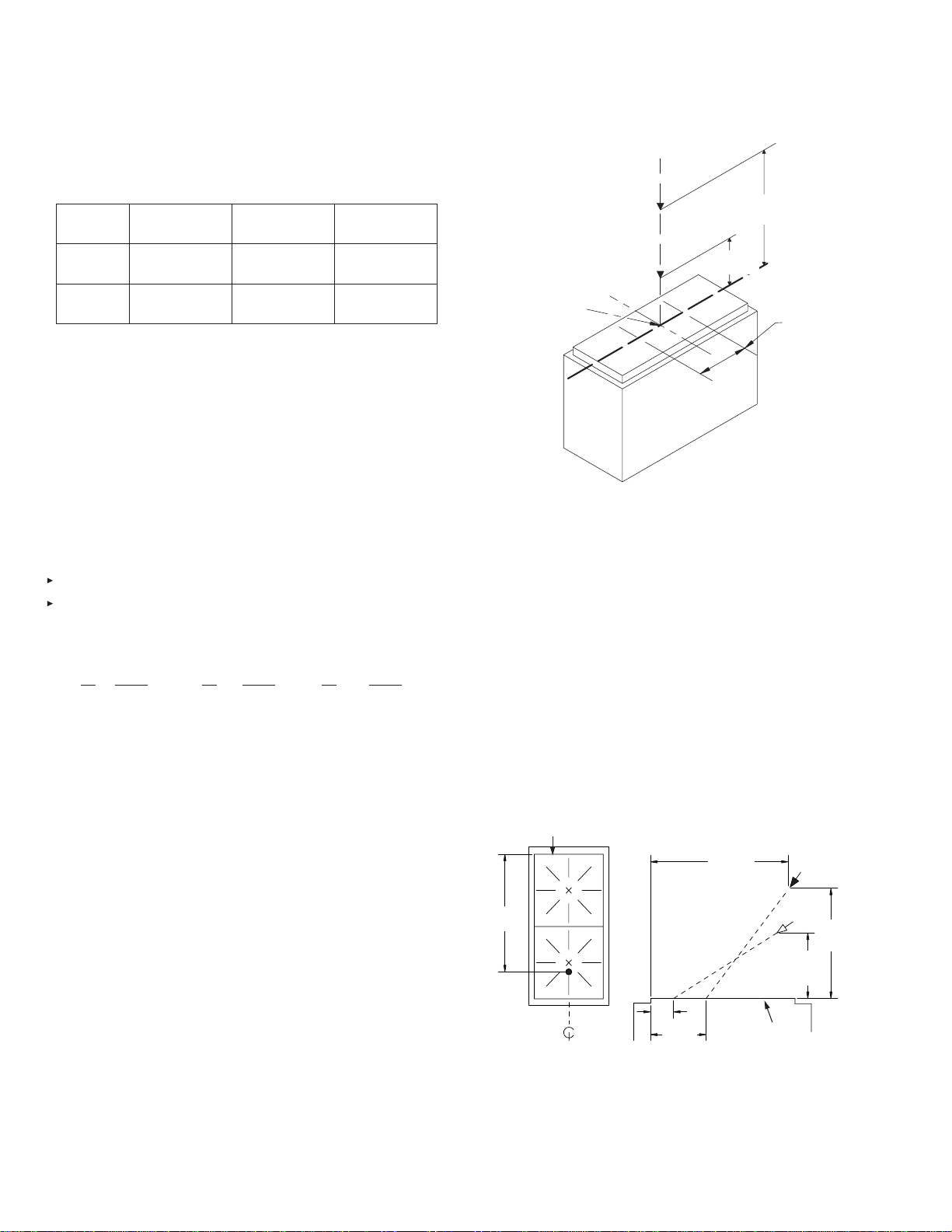
The following nozzle position and coverage limitations must be followed:
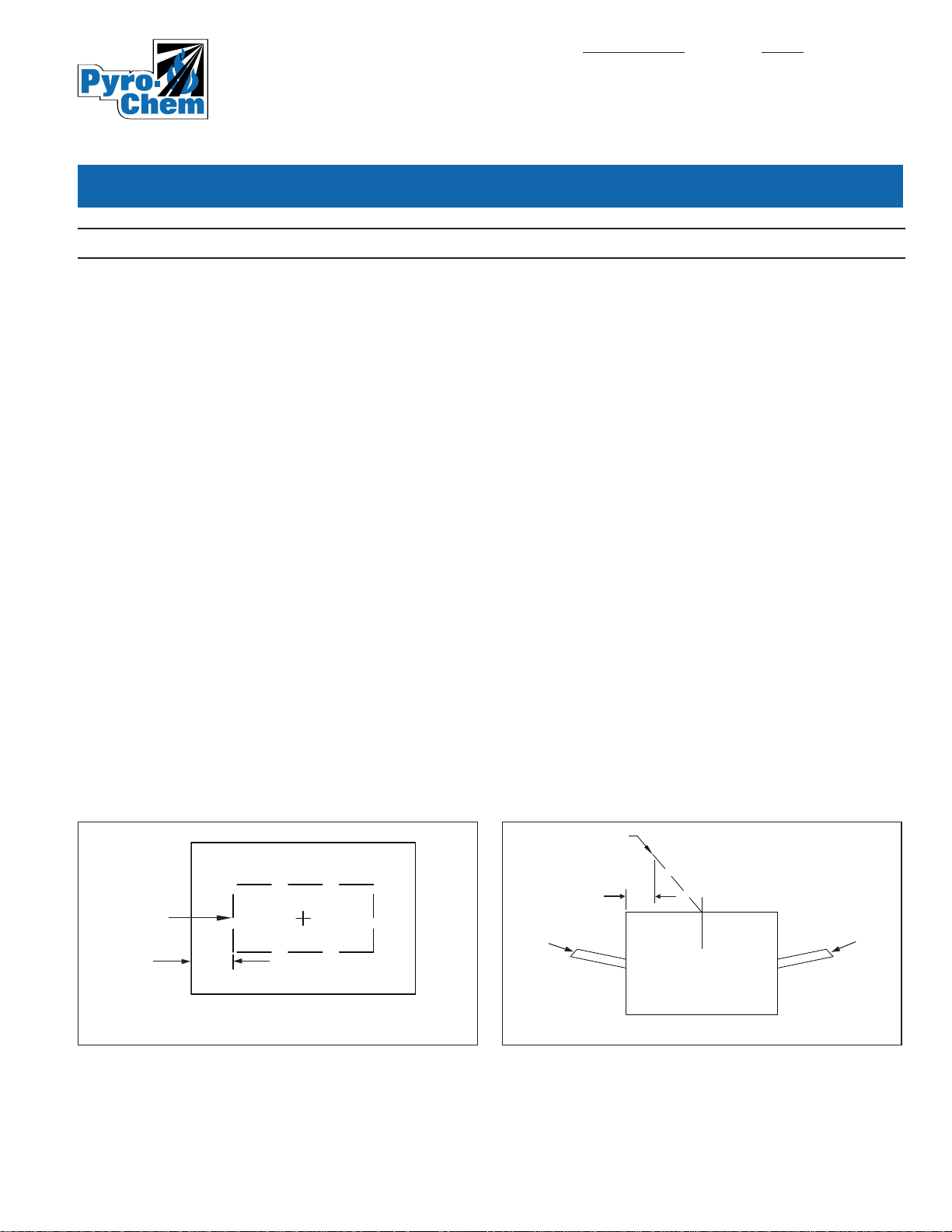
Nozzle quantity............One
Nozzle type..................2L
Nozzle height...............20 in. (508 mm)
Nozzle location............6 1/2 in. (165 mm) inside from outside edge of the appliance top
Nozzle aim point.........Aimed at center of catalyst
2L NOZZLE
BACK
6 1/2 IN. (165 mm)
FROM OUTSIDE
EDGE OF THE
APPLIANCE
TOP VIEW
FRONT
008095
6 1/2 IN. (165 mm)
FROM OUTSIDE EDGE
OF THE APPLIANCE
PRODUCT
OUTPUT
BACK
SIDE VIEW
FRONT
PRODUCT
INPUT
008096
If you should have any questions pertaining to this bulletin, please contact your Territory Sales Manager or call
Technical Services at 1-800-526-1079 or 1-715-732-3465.
ULEX 3830
Page 4

Page 5

KITCHEN KNIGHT II Restaurant Fire Suppression Manual
This manual is intended for use with PYRO-CHEM KITCHEN
KNIGHT II Restaurant Fire Suppression Systems.
Those who install, operate, recharge, or maintain these fire
suppression systems should read this entire manual. Specific
sections will be of particular interest depending upon one’s
responsibilities.
Design, installation, recharge, and maintenance of the system
must conform to the limitations detailed in this manual and performed by an individual who attended a PYRO-CHEM training
program and became trained to install, recharge, design, and
maintain the PYRO-CHEM system.
Fire suppression systems are mechanical devices. They need
periodic care. Maintenance is a vital step in the performance
of your fire suppression system. As such it must be performed
in accordance with NFPA 96 (Standard for the Installation
of Equipment for the Removal of Smoke and Grease-Laden
Vapors from Commercial Cooking Equipment) and NFPA
17A (Standard on Wet Chemical Extinguishing Systems) by
an authorized PYRO-CHEM distributor. To provide maximum
assurance that the fire suppression system will operate effectively and safely, maintenance must be conducted at six-month
intervals, or earlier if the situation dictates. Twelve-year maintenance must include agent tank hydrostatic testing.
FOREWORD
UL EX3830 ULC EX3830
2014-NOV-10 REV. 06
PART NO. 551274-06
PYRO-CHEM, KITCHEN KNIGHT, and the product names listed in this material are marks
and/or registered marks. Unauthorized use is strictly prohibited.
Page 6

EXPLANATION OF SAFETY ALERTS
UL EX3830 ULC EX3830
REV. 06 2014-NOV-10
KITCHEN KNIGHT II Restaurant Fire Suppression Manual
p
Indicates a hazardous situation in which a person will experience serious personal injury or death if the situation is not
avoided.
Indicates a hazardous situation in which a person could experience serious personal injury or death if the situation is not
avoided.
Indicates a hazardous situation in which a person could experience minor or moderate personal injury if the situation is not
avoided.
DANGER
!
WARNING
!
CAUTION
!
CAUTION
Addresses practices not related to personal injury, such as
a system part malfunctioning, property damage, or system
failure.
NOTICE
Addresses general practices or observations
related to system function that are not related
to personal injury.
Page 7
KITCHEN KNIGHT II Restaurant Fire Suppression Manual
UL EX3830 ULC EX3830
UL EX3830 ULC EX3830
2014-NOV-10 REV. 06 PAGE 1
2014-NOV-10 REV. 06 PAGE 1
REVISION RECORD
DATE PAGE REV. NO. DATE PAGE REV. NO.
2014-NOV-10 Complete manual has
been reformatted along
with several revised
pages that contain
updated technical
information. For clarity,
all pages have been
changed to Revision 06,
regardless of previous
revision number.
Technical information
changes have been
noted with a revision
indicator (u).
Indicates revised information.
Indicates change in page sequence.
Page 8

KITCHEN KNIGHT II Restaurant Fire Suppression ManualREVISION RECORD
UL EX3830 ULC EX3830
PAGE 2 REV. 06 2014-NOV-10
DATE PAGE REV. NO. DATE PAGE REV. NO.
Indicates revised information.
Indicates change in page sequence.
Page 9

KITCHEN KNIGHT II Restaurant Fire Suppression Manual
TABLE OF CONTENTS
UL EX3470 ULC EX3470
2014-NOV-10 REV. 06 PAGE TOC-1
SECTION PAGES
1. GENERAL INFORmATION
INTRODUCTION 1-1
Temperature Limitations 1-1
UL Listing 1-1
ULC Listing 1-1
MEA Approval 1-1
2. COmPONENTS
CYLINDERS & VALVE 2-1
WET VALVE REBUILDING EQUIPMENT 2-1
Wet Valve Seal Rebuilding Kit 2-1
Pressure Regulator Assembly 2-2
Pressure Regulator Rebuilding Kit 2-2
Model VT-1 Tool 2-2
CYLINDER BRACKETING 2-2
EXTINGUISHING AGENT 2-2
MCH3 MECHANICAL CONTROL HEAD 2-3
ECH3 ELECTRICAL CONTROL HEAD 2-3
NMCH3 MECHANICAL CONTROL HEAD 2-3
EN-MCU3 ENCLOSURE 2-3
EN-S ENCLOSURE 2-4
16 GRAM CO2 CARTRIDGE 2-4
MB-P2 MOUNTING BRACKET 2-4
PNEUMATIC ACTUATING CYLINDERS 2-4
Model PAC-10 2-4
DETECTION EQUIPMENT 2-5
Model FLK-1 2-5
Model FLK-1A 2-5
Model FLH-1 2-5
A-PC Fusible Links 2-6
Thermal Detectors 2-6
Flexible Conduit 2-6
RPS-M – REMOTE PULL STATION 2-7
“QUIK-SEAL” ADAPTOR 2-7
“COMPRESSION-SEAL” ADAPTOR 2-7
“HOOD SEAL” ADAPTOR ASSEMBLY 2-7
GAS SHUT-OFF VALVES 2-8
GV Shut-off Valve 2-8
EGVSO Gas Shut-off Valve 2-8
CORNER PULLEYS 2-9
SBP-1 Corner Pulley 2-9
CBP-1 Corner Pulley 2-9
WBP-1 Corner Pulley 2-9
TEE PULLEY 2-9
WIRE ROPE 2-9
ELECTRICAL SWITCHES 2-10
SM-120 SOLENOID MONITOR 2-10
PIPE AND FITTINGS 2-10
AGENT DISTRIBUTION HOSE AND 2-11
RESTRAINING CABLE KIT 2-11
STAINLESS STEEL ACTUATION HOSE 2-11
SECTION PAGES
NOZZLES 2-11
RUBBER BLOW-OFF CAPS 2-11
SWIVEL ADAPTOR 2-11
NOZZLE AIMING DEVICE 2-12
HORN/STROBE ASSEMBLY 2-12
COMPONENTS LIST 2-13
3. SYSTEm DESIGN
GENERAL 3-1
NOZZLE COVERAGE AND PLACEMENT 3-1
Duct Protection 3-1
Modularizing Duct 3-2
Transition Ducts 3-3
Electrostatic Precipitator 3-3
Plenum Protection 3-3
Appliance Protection 3-4
Design Chart 3-4
Fryers 3-5
Range (Small) 3-6
High-Proximity Backshelf 3-7
Range (Large) 3-7
Nozzle Positioning Table 3-7
Small Wok 3-9
Large Wok 3-9
Small Griddle 3-10
Large Griddle 3-10
Radiant/Electric Char-Broiler 3-11
Lava Rock Char-Broiler 3-11
Natural Charcoal Char-Broiler 3-12
Mesquite Char-Broiler 3-12
Salamander Broiler 3-12
Upright/Salamander Broiler 3-13
Chain Broiler 3-13
Tilt Skillet/Braising Pan 3-14
SPECIFIC APPLICATION BY MODEL 3-15
Henny Penny Fryer – Models 690, 691, 692 3-15
Henny Penny Fryer – Models 580, 3-16
581, 582, 590, 591, 592, 680, 682
Nieco Broiler – Model MPB-84 3-17
Nieco Broiler – Model JF94E 3-17
Baker’s Pride Broilers 3-18
PIPING LIMITATIONS 3-18
General Piping Requirements 3-19
Design Steps 3-19
DETECTOR PLACEMENT 3-23
Exhaust Duct(s) 3-23
Electrostatic Precipitator 3-23
Cooking Appliance(s) 3-24
Page 10

TABLE OF CONTENTS
UL EX3470 ULC EX3470
PAGE TOC-2 REV. 06 2014-NOV-10
KITCHEN KNIGHT II Restaurant Fire Suppression Manual
SECTION PAGES
4. SYSTEm INSTALLATION
GENERAL 4-1
CYLINDER INSTALLATION 4-1
CONTROL HEAD INSTALLATION 4-1
Single Cylinder Installation 4-1
Multiple Cylinder Installation 4-2
DETECTOR INSTALLATION 4-4
Fusible Link Detection 4-4
Fusible Links Without Hangers 4-5
Fusible Links With Link Hangers 4-6
Thermal Detection 4-6
SETTING THE CONTROL HEAD 4-7
MCH3/NMCH3 Control Head 4-7
ECH3 Control Head 4-7
SOLENOID MONITOR INSTALLATION 4-8
In Detection Circuit 4-8
Solenoid Monitor When Used as a 4-8
Reset Relay
REMOTE PULL STATION INSTALLATION 4-8
GAS SHUT-OFF VALVE INSTALLATION 4-10
Mechanical Gas Shut-off 4-10
Valve Installation
Electrical Gas Shut-off Valve Installation 4-11
PULLEY TEE INSTALLATION 4-11
ELECTRICAL (SNAP-ACTION) SWITCH 4-11
INSTALLATION
PIPE AND NOZZLE INSTALLATION 4-12
INSTALLATION INSTRUCTIONS FOR 4-13
CASTERED/MOVEABLE EQUIPMENT
USING AGENT DISTRIBUTION HOSE
Critical Installation Requirements 4-13
AGENT DISTRIBUTION HOSE INSTALLATION 4-13
General Requirements 4-13
Installation Requirements 4-13
Restraining Cable Installation 4-14
Final Installation Guidelines and 4-15
Checkout Procedures
Agent Distribution Hose/Restraining 4-16
Cable Six-Month Maintenance
Blank Page 4-17
SYSTEM CHECKOUT AFTER INSTALLATION 4-18
Model MCH3/NMCH3 Mechanical 4-18
Control Head
Model ECH3-24/120 Electrical 4-18
Control Head
Testing Thermal Detectors 4-18
Testing Remote Pull Station 4-18
Completing System Checkout 4-19
ENCLOSURE INSTALLATION INSTRUCTIONS 4-19
– MODEL EN-MCU3 AND MODEL EN-S
Enclosure Mounting 4-19
Fusible Link Detector Installation 4-20
SECTION PAGES
Setting the EN-MCU3 4-20
Remote Pull Station Installation 4-20
Gas Shut-off Valve Installation 4-20
Electrical (Snap-Action) Switch Installation 4-21
Cylinder Installation 4-21
Single Cylinder Installation 4-21
Multiple Cylinder Installation 4-22
System Checkout After Installation 4-22
FLEXIBLE CONDUIT INSTALLATION 4-23
Design Requirements 4-23
Installation Requirements 4-24
Connecting Flexible Conduit to Control 4-24
Head, Electrical Box, Pull Station, or
Mechanical Gas Valve
Connecting Flexible Conduit to Pulley 4-26
Elbows, Pulley Tees, or Union Fittings
Installing Flexible Conduit Through a 4-27
Conduit Offset
Flexible Conduit Splicing 4-29
Testing Pull Station/Mechanical Gas Valve 4-31
5. SYSTEm mAINTENANCE
GENERAL 5-1
SEMI-ANNUAL MAINTENANCE 5-1
ANNUAL MAINTENANCE 5-1
12-YEAR MAINTENANCE 5-2
6. SYSTEm REChARGE
GENERAL 6-1
SYSTEM CLEANUP 6-1
SYSTEM RECHARGE 6-1
Page 11

KITCHEN KNIGHT II Restaurant Fire Suppression Manual
SECTION 1 – GENERAL INFORMATION
UL EX3830 ULC EX3830
2014-NOV-10 REV. 06 PagE 1-1
INTRODUCTION
This manual is intended for use with PYRO-CHEM
KITCHEN
KNIgHT II Restaurant Fire Suppression Systems. Those who
install, operate, recharge, or maintain these fire suppression
systems should read this entire manual. Specific sections will
be of particular interest depending upon one’s responsibilities.
Design, installation, recharge, and maintenance of the system
must conform to the limitations detailed in this manual and
performed by an individual who attended a PYRO-CHEM training program and became trained to install, recharge, design,
and maintain the PYRO-CHEM system.
Fire suppression systems are mechanical devices. They need
periodic care. Maintenance is a vital step in the performance
of your fire suppression system. as such, it must be performed
in accordance with NFPa 96 (Standard for the Installation
of Equipment for the Removal of Smoke and grease-Laden
Vapors from Commercial Cooking Equipment) and NFPa
17a (Standard on Wet Chemical Extinguishing Systems) by
an authorized PYRO-CHEM distributor. To provide maximum
assurance that the fire suppression system will operate effectively and safely, maintenance must be conducted at six-month
intervals, or earlier if the situation dictates. Twelve-year maintenance must include agent tank hydrostatic testing.
The PYRO-CHEM KITCHEN KNIgHT II Pre-Engineered System
utilizes a wet chemical agent specifically designed to suppress
restaurant cooking area fires. The system provides automatic
actuation and can be manually actuated through a remote
mechanical pull station. Upon actuation, the system discharges
a pre-determined amount of agent to the duct, plenum, and
cooking appliances. The agent acts to suppress fires in three
ways:
1. The chemical chain reaction causing combustion is interrupted by both the agent itself and the resulting steam
formation.
2. The agent cools the fire bringing it below auto-ignition
temperature.
3. The agent reacts with hot grease forming a soap-like layer
(saponification) that helps prevent the escape of combustible vapors, thus preventing re-ignition.
The shutdown of all sources of fuel and electric power that
produce heat to all equipment protected by the system is
required upon system actuation. Make up or supply air fans,
integral to the exhaust hood(s) being protected, shall be shut
down upon system actuation. Exhaust fan(s) in the ventilation
system should remain on during system discharge as they
assist the dispersion of chemical through the ventilating system.
The system is UL Listed with or without exhaust fan shutdown.
The KITCHEN KNIgHT II and the KITCHEN KNIgHT Restaurant
Fire Suppression System are compatible as long as separate
installation guidelines are followed per each system design
manual. Exception: The actuation limitations for the KITCHEN
KNIgHT II system may be utilized for the KITCHEN KNIgHT
system. also, control heads, prior to Model No. 3, may be
utilized on KITCHEN KNIgHT II systems, provided that the
limitations used with those control heads are followed.
Temperature Limitations
The operating temperature range of the PYRO-CHEM
KITCHEN KNIgHT II System is 32 °F (0 °C) minimum to
120 °F (49 °C) maximum.
UL Listing
The PYRO-CHEM KITCHEN KNIgHT II Restaurant Fire
Suppression System has been tested to the UL Standard
for Fire Extinguishing Systems For Protection of Restaurant
Cooking areas, UL300 and Listed by Underwriters Laboratories,
Inc.
ULC Listing
The PYRO-CHEM KITCHEN KNIgHT II Restaurant Fire
Suppression System is listed by Underwriters Laboratories of
Canada (ULC). The ULC Listing No. is EX3830.
MEA Approval
The PYRO-CHEM KITCHEN KNIgHT II Restaurant Fire
Suppression System has been approved for use by MEa
(Material and Equipment acceptance Division) for New York
City. The MEa Certification No. is 249-03-E.
Page 12

SECTION 1 – GENERAL INFORMATION
UL EX3830 ULC EX3830
PagE 1-2 REV. 06 2014-NOV-10
NOTES:
KITCHEN KNIGHT II Restaurant Fire Suppression Manual
Page 13
KITCHEN KNIGHT II Restaurant Fire Suppression Manual
CYLINDERS & VALVE
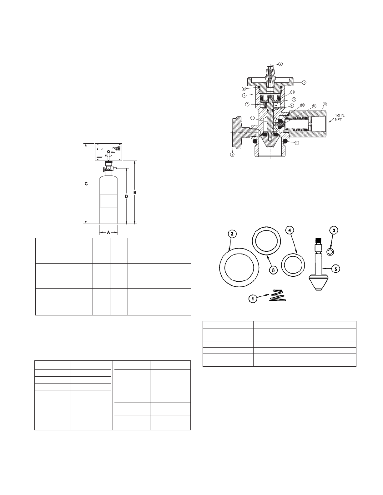
The PYRO-CHEM KITCHEN KNIgHT II System has available
four different size cylinders: Models PCL-160 (Part No. 553163),
PCL-300 (Part No. 551194), PCL-460 (Part No. 551193), and
PCL-600 (Part No. 551196). Cylinder sizes are expressed in
terms of extinguishing agent capacity (i.e., the PCL-300 uses
3.0 gallons (11.4 L) of extinguishing agent). The cylinder is
manufactured, tested, and meets DOT requirements. Cylinders
come pre-filled with extinguishing agent and are charged with
dry nitrogen to a pressure of 225 psig @ 70° F (15.5 bar @
21 °C). Cylinder and valve assembly dimensions are shown in
Figure 2-1.
SECTION 2 – COMPONENTS
UL EX3830 ULC EX3830
2014-NOV-10 REV. 06 PagE 2-1
FIguRE 2-2
006212PC
WET VALVE REBuILDINg EQuIPMENT
Wet Valve Seal Rebuilding Kit
after system discharge, the valve assembly must be rebuilt to
ensure proper future operation. The Wet Valve Seal Re build ing
Kit (Part No. 550698) should be used. It includes all components
necessary to properly rebuild the valve. See Figure 2-3.
Max.
a B C D Flow Weight Mounting
Model in. in. in. in. Point lb Bracket
No. (mm) (mm) (mm) (mm) Capacity (kg) Used
PCL-160 8.00 17.75 23.50 15.44 5 34 MB-15
(203) (451) (597) (392) (15.4)
PCL-300 8.00 25.06 30.81 22.75 10 53 MB-15
(203) (637) (783) (578) (24.0)
PCL-460 10.00 25.06 30.81 22.75 15 83 MB-15
(254) (637) (783) (578) (37.6)
PCL-600 10.00 35.81 41.56 33.50 20 108 MB-1
(254) (910) (1056) (851) (49.0)
FIguRE 2-1
002841PC
all cylinders utilize the same Wet Valve assembly (Part No.
551175). The wet valve assembly is a pressure sealed poppet
type valve designed to provide rapid actuation and discharge of
agent. See Figure 2-2.
Item Part No. Description
1 Valve Body
2 550705 Conical Spring
3 550707 Piston
4 550716 Neck O-Ring
5 551236 Pressure gauge
6 550028 Stem O-Ring
7 550802 Wet Valve
adaptor
Item Part No. Description
8 550386 Shrader Valve
Ass’y
9 550714 Valve Cap O-Ring
10 550715 Piston O-Ring
11 550989 Valve Stem
12 551256 Pressure
Regulator
13 551261 Seal
14 17851 6-32x3/8 Screw
FIguRE 2-3
002906PC
Item Part Number Description
1 550705 Conical Spring
2 550716 Neck O-Ring
3 550028 Stem O-Ring
4 550715 Piston O-Ring
5 550989 Valve Stem
6 550714 Valve Cap O-Ring
Pressure Regulator Assembly
The pressure regulator assembly (Part No. 550985) is available
if the complete regulator requires replacement (e.g. possible
thread damage).
Page 14
SECTION 2 – COMPONENTS
UL EX3830 ULC EX3830
PagE 2-2 REV. 06 2014-NOV-10
WET VALVE REBuILDINg EQuIPMENT (Continued)
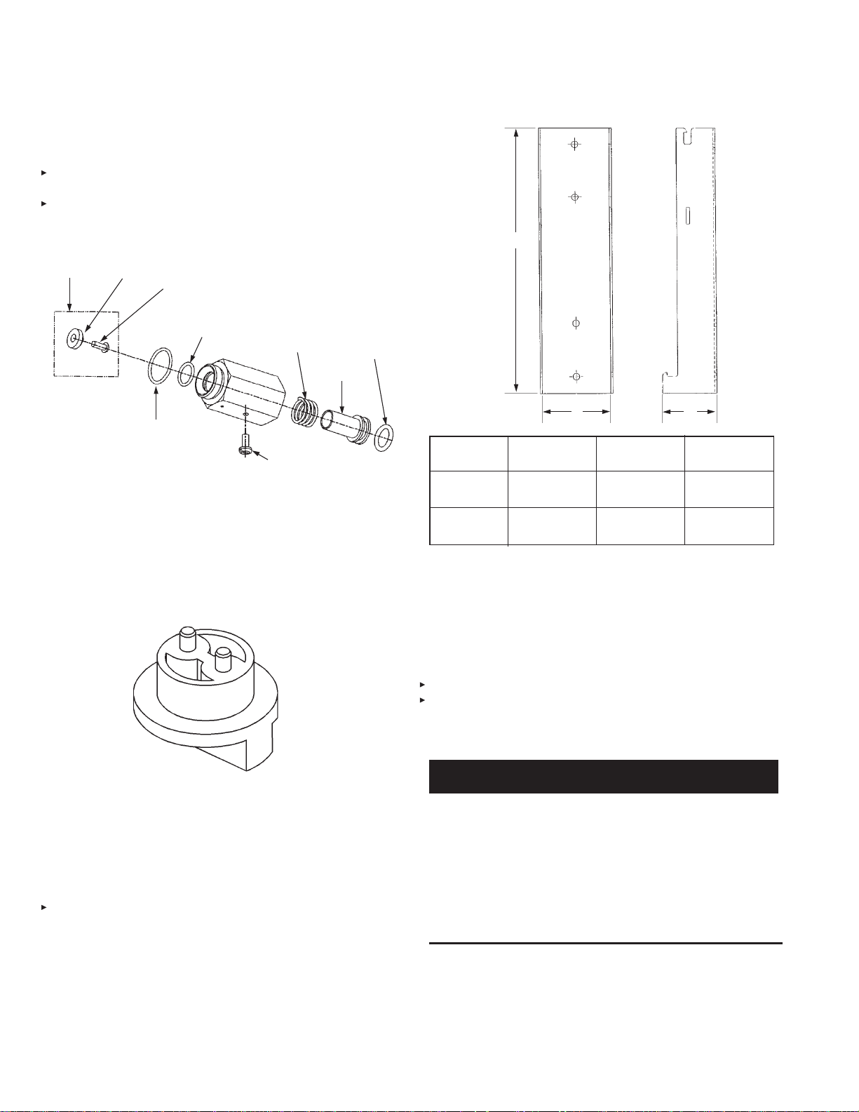
Pressure Regulator Rebuilding Kit
after system discharge and at hydrotest intervals, the pressure
regulator must be rebuilt to ensure proper future operation. The
Pressure Regulator Rebuilding Kit (Part No. 551061) should be
used. It includes all components and instructions necessary to
properly rebuild the regulator. See Figure 2-4.
IN VaLVE
BODY
SEaL (PaRT
NO. 551261)
#6-32 X 3/8 IN. SCREW
(PaRT NO. 17851)
KITCHEN KNIGHT II Restaurant Fire Suppression Manual
a
INTERNaL O-RINg
(PaRT NO. 402745)
EXTERNaL O-RINg
(PaRT NO. 551273)
SPRINg (PaRT
NO. 551176)
#8-32 X 3/8 IN.
HOLDINg SCREW
(PaRT NO. 419045)
PISTON
O-RINg
(PaRT NO.
12837)
PISTON
FIguRE 2-4
006103PC
Model VT-1 Wet Valve Tool
The Model VT-1 Wet Valve Tool (Part No. 550788) is designed
to facilitate the rebuilding of the wet valve assembly. It should be
used to hold the wet valve piston while unscrewing the cap and
stem assembly. See Figure 2-5.
B C
Model No. a B C
MB-15 15.69 in. 4.0 in. 3.13 in.
(399 mm) (102 mm) (7.9 mm)
MB-1 20.44 in. 4.0 in. 2.13 in.
(519 mm) (10\2 mm) (5.4 mm)
FIguRE 2-6
006842PC
EXTINguISHINg AgENT
The agent used in PYRO-CHEM KITCHEN KNIgHT II Systems
is a potassium carbonate based solution that is extremely effective for grease-related kitchen fires. This agent is available for
cylinder recharging in 1.6 gallon and 3.0 gallon containers. For
MSDS information, contact Tyco Fire Protection Products or visit
www.pyrochem.com.
1.6 gallon Shipping assembly – Part No. 553176
3.0 gallon Shipping assembly – Part No. 551188
FIguRE 2-5
002907PC
CYLINDER BRACKETINg
Vertical bracketing of the PCL-160, PCL-300 and PCL-460 is
provided by the Model MB-15 Bracket Kit (Part No. 550054).
Vertical bracketing of the PCL-600 is provided by the Model
MB-1 Bracket Kit (Part No. 550053). See Figure 2-6. These kits
must be ordered separately with each cylinder/valve assembly.
Cylinder installation instructions are provided in the installation
section of this manual.
CAuTION
!
Precautions must be taken when handling and transferring
wet agents as they are caustic in nature. goggles must be
worn at all times. If any agent gets into the eyes, they should
be flushed with clean water for 15 minutes and a physician
contacted. If any agent contacts the skin, it should be flu shed
with cold water to prevent irritation. The agent is electrically
conductive. Care must be taken to thoroughly clean up any
agent discharged around electrical appliances before turning
the power on.
after system discharge, agent must be cleaned up immediately
with hot, soapy water to prevent corrosion of affected surfaces.
Page 15
KITCHEN KNIGHT II Restaurant Fire Suppression Manual
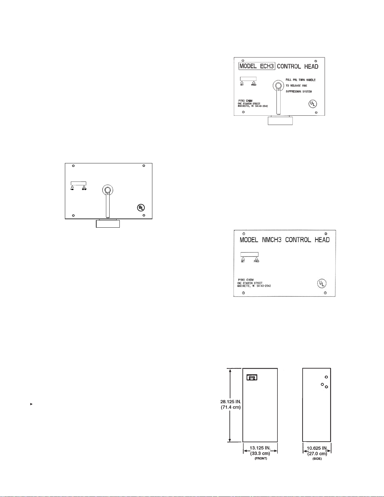
MODEL MCH3 – MECHANICAL CONTROL HEAD
The Model MCH3 Mechanical Control Head (Part No. 551200)
is a fully mechanical control head which can be connected to
the PCL-160/300/460/600 cylinder valve. This control head will
support a fusible link detection system, a remote mechanical pull
station (Model RPS-M), and a mechanical or electric gas shutoff valve. a micro electric switch (Model MS-SPDT, MS-DPDT,
MS-3PDT, or MS-4PDT) can be ordered separately and field
installed. It is equipped with a local manual control handle that
allows for mechanical system actuation. Operation of the local
manual control requires removing the pull pin and rotating the
handle clockwise. The Model MCH3 control head can actuate a
maximum of five cylinders with the 16 gram CO
cartridge. See
2
Figure 2-7.
MODEL MCH3 CONTROL HEAD
PULL PIN, TURN HANDLE
FIRED
SET
PYRO-CHEM
ONE STANTON STREET
MARINETTE, WI 54143-2542
TO RELEASE FIRE
SUPPRESSION SYSTEM
SECTION 2 – COMPONENTS
UL EX3830 ULC EX3830
2014-NOV-10 REV. 06 PagE 2-3
FIguRE 2-8
004789PC
MODEL NMCH3 – MECHANICAL CONTROL HEAD
The Model NMCH3 Mechanical Control Head (Part No. 551203)
is a fully mechanical control head which can be connected to
the PCL-160/300/460/600 cylinder valve. This control head will
support a fusible link detection system, a remote mechanical pull
station (Model RPS-M), and a mechanical or electric gas shutoff valve. an electrical (snap-action) switch (Model MS-SPDT,
MS-DPDT, MS-3PDT, or MS-4PDT) can be ordered separately
and field installed. There is no local manual actuation for the
Model NMCH. The Model NMCH3 control head can actuate a
maximum of five cylinders with the 16 gram CO
cartridge.
2
FIguRE 2-7
004790PC
MODEL ECH3 – ELECTRIC CONTROL HEAD
The Model ECH3 electric control head is an electrically operated
control head which can be connected to the PCL-160/300/460/600
cylinder valve. This control head will support an electric thermal
detection system, a remote mechanical pull station (Model
RPS-M), and an electric gas shut-off valve. It will not support
a fusible link detection system. an electric (snap-action) switch
(Model MS-DPDT) is included.
The Model ECH3 control head is available in both 120VaC
(Model ECH3-120 (Part No. 551202)) and 24VDC (Model
ECH3-24 (Part No. 551201)). It is equipped with a local manual
control handle that allows for mechanical system actuation.
Operation of the local manual control requires removing the pull
pin and rotating the handle clockwise. The Model ECH3 control
head can actuate a maximum of five cylinders with the 16 gram
CO
cartridge. See Figure 2-8.
2
Note: When utilizing electric detection, it is recommended that
the Model ECH3-24 electric control head be used with either
the aUTOPULSE 542R Control Panel (Part No. 433607) or
the aUTOPULSE Z-10 Control Panel (Part No. 430525). If the
ECH3-120 control head is to be utilized, it must be used with
Solenoid Monitor, Model SM-120 (Part No. 550302), along with
a UL Listed 1a, 120VaC power supply (by others), in accordance with NFPa 17a, NFPa 96, and the local authority having
jurisdiction.
FIguRE 2-9
006843PC
MODEL EN-MCu3 ENCLOSuRE
The Model EN-MCU3 Enclosure (Part No. 551208) is used for
vertical mounting of a single PCL-160, PCL-300 or PCL-460.
The EN-MCU3 also includes a mechanical control unit, eliminating the need for a Model MCH3 control head. See Figure 2-10.
Note: The PCL-600 cannot be mounted in an EN-MCU3.
FIguRE 2-10
002845PC
Page 16
SECTION 2 – COMPONENTS
UL EX3830 ULC EX3830
PagE 2-4 REV. 06 2014-NOV-10
KITCHEN KNIGHT II Restaurant Fire Suppression Manual
MODEL EN-S ENCLOSuRE
The Model EN-S Enclosure (Part No. 550966) is used for vertical
mounting of a single PCL-160, PCL-300 or PCL-460 when it is
used as a secondary agent cylinder in a system. Dimensions
are the same as the Model EN-MCU3 enclosure (see Figure
2-10). The EN-S has no control mechanism, and must be used
in conjunction with a Model EN-MCU3 enclosure or a Model
MCH3/ECH3 control head. Note: The PCL-600 cannot be
mounted in an EN-S enclosure.
16 gRAM CO2 CARTRIDgE
The 16 gram CO
Cartridge (Part No. 551059) is required to
2
pneumatically actuate the tank valve. The cartridge is installed in
the control head on top of the tank valves. The cartridge shipping
assembly contains six cartridges.
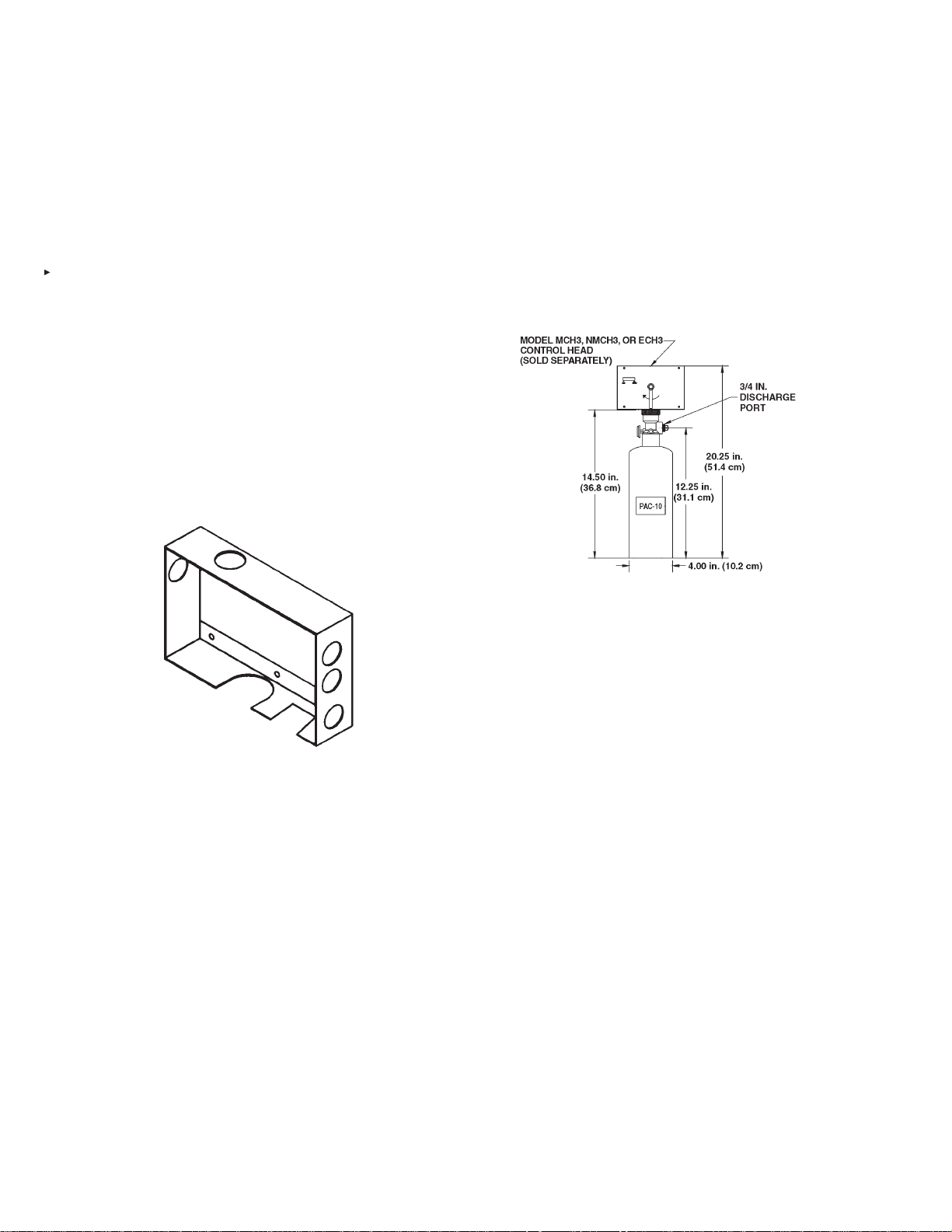
MODEL MB-P2 – CONTROL HEAD MOuNTINg BRACKET
The Model MB-P2 Mounting Bracket (Part No. 550853) must
be used to mount the Model MCH3, NMCH3, or ECH3 control
heads if the control head is not mounted directly on a cylinder
valve. See Figure 2-11.
PNEuMATIC ACTuATINg CYLINDERS
Model PAC-10
The Model PaC-10 (Part No. 550104) is a pneumatic actuating
cylinder that can actuate a maximum of ten agent cylinders
simultaneously. The Model PaC-10 includes a DOT 4Ba350
cylinder pressurized with dry nitrogen to 350 psig @ 70° F
(24.1 bar @ 21 °C), a brass valve with pressure gauge, and
a wall mounting bracket. a Model MCH3, NMCH3, or ECH3
control head must be purchased separately and connected to
the PaC-10 to open the valve. See Figure 2-12.
FIguRE 2-12
002847PC
FIguRE 2-11
002846PC
Page 17
KITCHEN KNIGHT II Restaurant Fire Suppression Manual
SECTION 2 – COMPONENTS
UL EX3830 ULC EX3830
2014-NOV-10 REV. 06 PagE 2-5
DETECTION EQuIPMENT
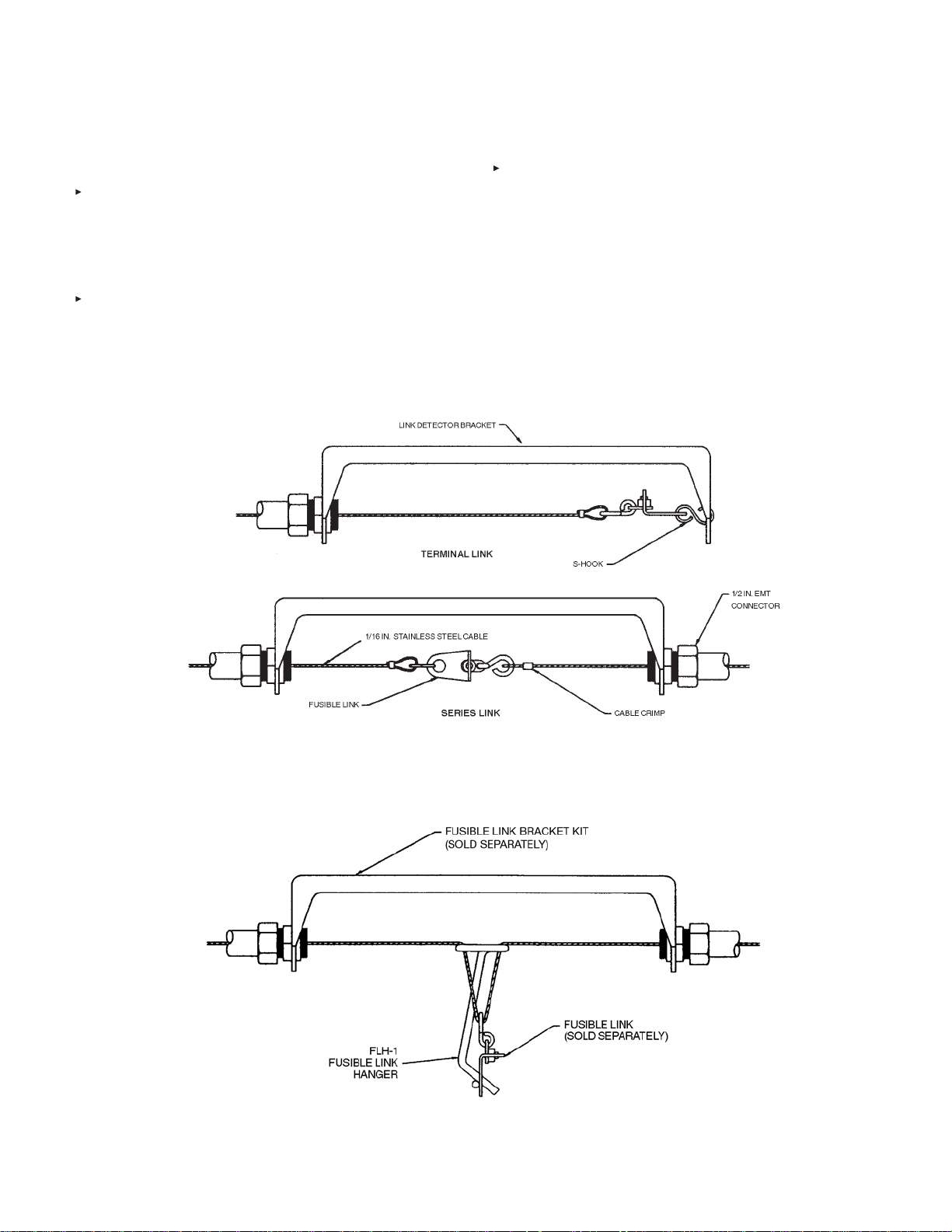
Model FLK-1 Assembly
The Model FLK-1 assembly (Part No. 550131) includes a 10 in.
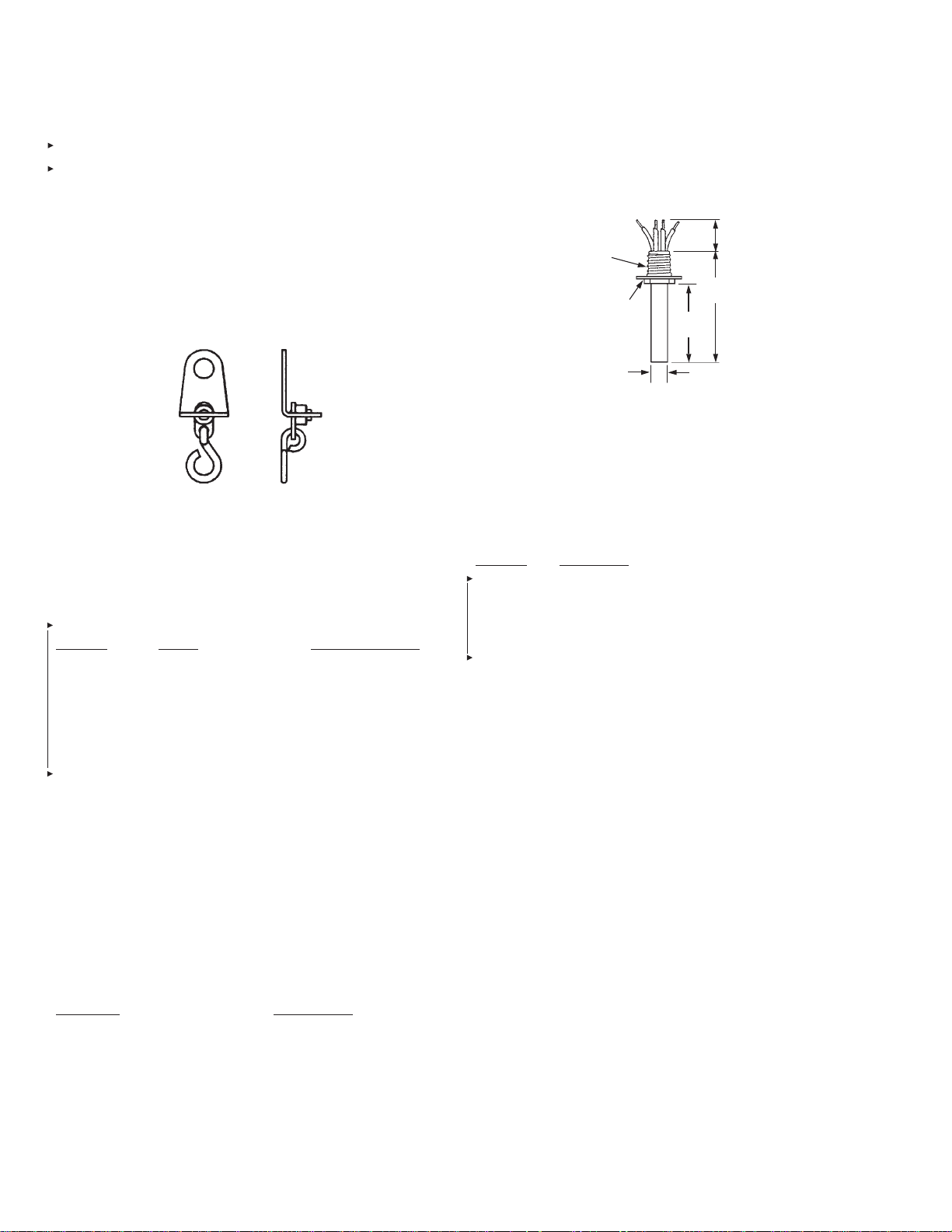
(254 mm) steel bracket, two 1/2 in. EMT connectors, two cable
crimps, and two “S” hooks. Fusible links must be ordered separately. See Figure 2-13.
Model FLK-1A Assembly
The Model FLK-1a assembly (Part No. 550132) includes an
8 in. (203 mm) steel bracket, two 1/2 in. EMT connectors, two
cable crimps, and two “S” hooks. Fusible links must be ordered
separately.
Model FLH-1 Assembly
The Model FLH-1 Fusible Link Hanger assembly (Part No.
550876) is an accessory designed to simplify the installation
of fusible links in the fusible link line. It can be used with the
Model FLK-1 fusible link kit (kits must be ordered separately).
The fusible link hanger makes it possible to install fusible links
without cutting and crimping loops in the fusible link line for each
link. They are available in packages of 25 (FLH-25) only. See
Figure 2-14.
FIguRE 2-13
FIguRE 2-14
002849PC
002850PC
Page 18
SECTION 2 – COMPONENTS
UL EX3830 ULC EX3830
PagE 2-6 REV. 06 2014-NOV-10
KITCHEN KNIGHT II Restaurant Fire Suppression Manual
A-PC Fusible Links
The a-PC fusible link is designed to separate at a specific
temperature, releasing tension from the fusible link line, causing
system actuation. See Figure 2-15.
Note: When possible, temperature readings should be taken
at each detector location to determine optimum fusible link
temperature ratings. Temperature can be recorded using
either a Maximum Registering Thermometer (Part No. 15240)
temperature tape (by others), or any other accurate thermometer
that will record the maximum temperature experienced at the
detector location.
FIguRE 2-15
002851PC
after determining the maximum ambient temperature at the
fusible link location, select the correct fusible link according to
the temperature condition chart below:
Fusible Link
Shipping To Be Used
assembly Temperature Where Temperature
Part No. Rating Does Not Exceed
439227 (10) 165 °F (74 °C) 100 °F (38 °C)
439228 (10) 212 °F (100 °C) 150 °F (66 °C)
439229 (10) 280 °F (138 °C) 225 °F (107 °C)
439230 (10) 360 °F (182 °C) 290 °F (143 °C)
439231 (10) 450 °F (232 °C) 360 °F (182 °C)
439232 (25) 500 °F (260 °C) 400 °F (204 °C)
Thermal Detectors
Rate-compensating thermal detectors are normally open,
mechanical contact closure switches designed to operate at a
factory preset temperature. They are available in four preset
temperatures which meet NFPa standards and are UL Listed
and FM approved. after determining the maximum ambient
temperature at the thermal detector location, select the correct
thermal detector according to the temperature condition chart
below:
Thermal Maximum
Detector ambient
Model No. Temperature Part Number
TD-225 155 °F (68 °C) 13976
TD-325 255 °F (124 °C) 13975
TD-450 380 °F (193 °C) 13974
TD-600 530 °F (277 °C) 13971
Note: a transient rush of warm air up to 40 °F (4 °C) per
minute may expand the shell, but not enough to trigger the unit.
Temperature increases over 40 °F (4 °C) per minute however,
may initiate an alarm condition.
6 IN. LEaDS
(152 mm))
1/2 – 14 NPT
4.9 IN.
1 IN.
HEX
5/8 IN.
(16 mm)
3.7 IN.
(93 mm)
(124 mm)
FIguRE 2-16
007354
Flexible Conduit
Flexible Conduit can be used with the Mechanical Pull Station
assemly (Part No. 551074) and Mechanical gas Valves.
Flexible Conduit eliminates the need for rigid EMT conduit in the
mechanical pull station and gas valve lines, significantly reducing the overall installation time.
Part No. Description
434525 Flexible Conduit – 500 ft (152.4 m)
435959 Flexible Conduit – 500 ft (152.4 m) and
Wire Rope – 500 ft (152.4 m)
439104 Pre-Fed Flexible Conduit assembly –
50 ft (15.2 m)
435979 Flexible Conduit Strain Relief (50-Pack)
434347 Flexible Conduit Insert (50-Pack)
436063 Conduit Offset (6-Pack)
436150 P-Clip (50-Pack)
79827 Compression Union, 1/2 in.
55813 1/2 in. Compression Connector
Page 19
KITCHEN KNIGHT II Restaurant Fire Suppression Manual
SECTION 2 – COMPONENTS
UL EX3830 ULC EX3830
2014-NOV-10 REV. 06 PagE 2-7
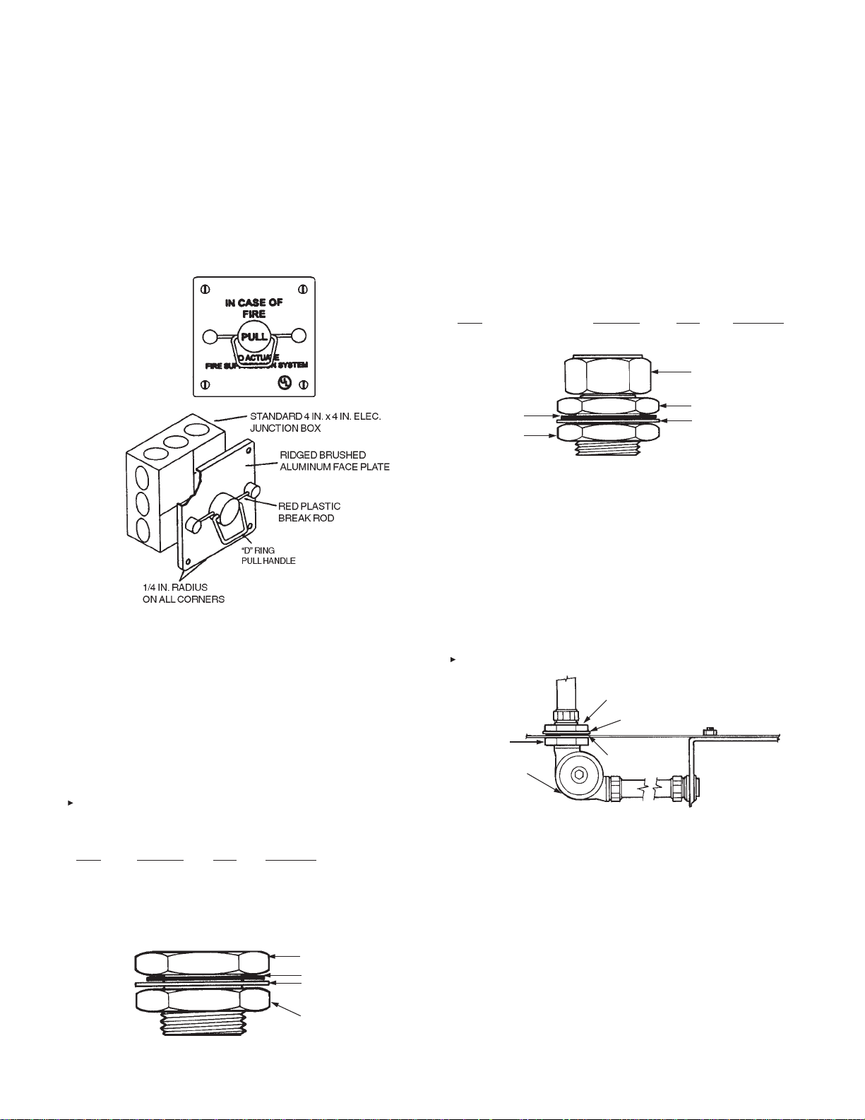
MODEL RPS-M – REMOTE MECHANICAL PuLL STATION
Remote manual control for the Model MCH3, NMCH3, or
ECH3 control head is provided by the Model RPS-M Remote
Mechanical Pull Station (Part No. 551074). It is connected to
the system control head by stainless steel cable. This cable is
enclosed in 1/2 in. EMT conduit with corner pulleys or flexible
conduit with bends and/or corner pulleys at each change in
direction. The remote mechanical pull station shall be located at
the point of egress. See Figure 2-17.
FIguRE 2-17
002852PC
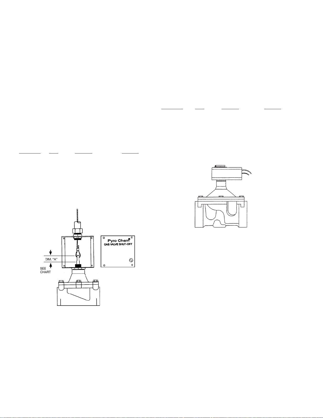
“QuIK-SEAL” ADAPTOR
The “Quik-Seal” adaptor is a listed mechanical bulkhead fitting
that produces a liquid-tight seal around both distribution piping
and detection conduit which runs through restaurant hoods
and ducts. The “Quik-Seal” adaptor accepts threaded pipe or
conduit. The adaptor is available for 3/8 in. and 1/2 in. pipe or
conduit sizes. When using with EMT conduit, a conduit connector must be installed in each end of the adaptor. The “Quik-Seal”
adaptor Shipping assembly can be ordered in single or package
of 24. See Figure 2-18.
Shipping
assembly Hole Size
Size Part No. Qty. Required
3/8 in. 550857 1 1 1/8 in.
1/2 in. 550859 1 1 1/8 in.
3/8 in. 550858 24 1 1/8 in.
1/2 in. 550860 24 1 1/8 in.
aDaPTOR BODY
gaSKET
LOCKWaSHER
“COMPRESSION-SEAL” ADAPTOR
This adaptor is a mechanical bulkhead fitting that produces a
liquid-tight seal around pipe and conduit when installing distribution piping and detection conduit through restaurant hoods and
ducts. The “Compression-Seal” adaptor is a straight-through
design requiring no cutting or threading of conduit or pipe. The
adaptor is available for EMT conduit size of 1/2 in. (Part No.
79152). See Figure 2-19. “Compression-Seal” adaptor Shipping
assembly must be ordered as stated below:
Shipping
assembly Hole Size
Size Part No. Qty. Required
1/2 in. EMT Conduit 79153 24 1 1/8 in.
COMPRESSION NUT
gaSKET
NUT
aDaPTOR BODY
LOCKWaSHER
FIguRE 2-19
“HOOD SEAL” ADAPTOR ASSEMBLY
This adaptor is a mechanical bulkhead fitting that produces a
liquid-tight seal around 1/2 in. EMT conduit when installing the
detection line through restaurant hoods and duct. The adaptor
accepts a high temperature pulley elbow and, when used,
correctly positions the elbow or conduit in line with the conduit
adaptor hole in the detector bracket. The “Hood Seal” eliminates
the need for multiple elbows when penetrating the top of a hood
when installing the detection line. “Hood Seal” adaptors are
available in quantities of six as Shipping assembly Part No.
423253. See Figure 2-20.
SEaL NUT
SEaL
aDaPTOR
BODY
PULLEY
ELBOW
(NOT PaRT
OF aSSEMBLY)
USE ONLY PULLEY ELBOW (PaRT NO. 423250)
WaSHER
gaSKET
000156
FIguRE 2-20
000156
NUT
FIguRE 2-18
000154
Page 20
SECTION 2 – COMPONENTS
UL EX3830 ULC EX3830
PagE 2-8 REV. 06 2014-NOV-10
KITCHEN KNIGHT II Restaurant Fire Suppression Manual
gAS SHuT-OFF VALVES
Note: gas valves are approved for indoor use only.
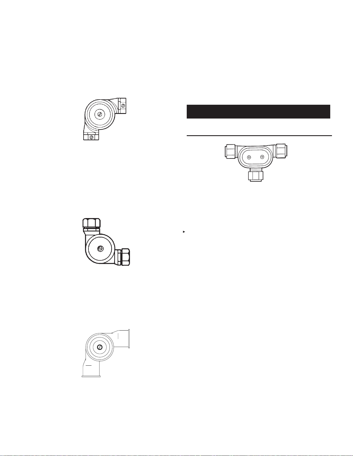
gV Mechanical gas Shut-off Valve
a gas shut-off valve is required on all systems used to protect
a gas fueled cooking appliance to stop gas flow in the event of
system actuation. a mechanical gas valve can be used with the
Model MCH3 and Model NMCH3 control heads. It is connected
to the system control head by stainless steel cable. This cable
is enclosed in 1/2 in. EMT conduit with a corner pulley at each
change in direction. The valves are rated for natural and LP gas
(see Figure 2-21). Mechanical gas valves are available in the
following sizes:
Note: Maximum operating pressure for all sizes of gV Mechanical
gas Valve is 5 psi (0.4 bar).
Valve Part
Model No. Size Dim. “a” Number
gV-75 3/4 in. 3/8 in. (9.5 mm) 550593
gV-100 1 in. 3/8 in. (9.5 mm) 550594
gV-125 1-1/4 in. 15/32 in. (12 mm) 550595
gV-150 1-1/2 in. 15/32 in. (12 mm) 550596
gV-200 2 in. 15/32 in. (12 mm) 551049
gV-250 2-1/2 in. 29/32 in. (23 mm) 550185
gV-300 3 in. 29/32 in. (23 mm) 550186
EgVSO Electric gas Shut-off Valve
a gas shut-off valve is required on all systems used to protect
a gas fueled cooking appliance to stop gas flow in the event of
system actuation. a UL Listed electric gas valve can be used
with either the Model MCH3 or ECH3 control head. The valves
are rated for natural and LP gas. Valves are available in 120VaC
(see Figure 2-22). Electric gas valves are available in the following sizes:
Valve Part
Model No. Size Dim. “a” Number
EgVSO-75 3/4 in. 50 psi (3.5 bar) 13707
EgVSO-100 1 in. 25 psi (1.7 bar) 13708
EgVSO-125 1-1/4 in. 25 psi (1.7 bar) 550360
EgVSO-150 1-1/2 in. 25 psi (1.7 bar) 13709
EgVSO-200 2 in. 25 psi (1.7 bar) 13710
EgVSO-250 2-1/2 in. 5 psi (0.3 bar) 550363
EgVSO-300 3 in. 5 psi (0.3 bar) 17643
FIguRE 2-21
002853PC
FIguRE 2-22
006844PC
Note: a UL Listed manual reset relay is required when using
an electric gas valve. The PYRO-CHEM KITCHEN KNIgHT II
Model SM-120 solenoid monitor must be used for this purpose.
Page 21
KITCHEN KNIGHT II Restaurant Fire Suppression Manual
SECTION 2 – COMPONENTS
UL EX3830 ULC EX3830
2014-NOV-10 REV. 06 PagE 2-9
CORNER PuLLEYS
Model SBP-1
a corner pulley is used whenever a change in stainless steel
cable direction is required. The Model SBP-1 Corner Pulley (Part
No. 415670) is equipped with a set screw fitting for connection to
1/2 in. EMT conduit. See Figure 2-23.
FIguRE 2-23
000160
Model CBP-1
a corner pulley is used whenever a change in stainless cable
direction is required. The Model CBP-1 (Part No. 423250) is a
grease-tight corner pulley designed for areas likely to experience
excessive deposit build-up. It is equipped with a compression
fitting for connection to 1/2 in. EMT conduit. See Figure 2-24.
Note: The Model CBP-1 is not a liquid tight seal for penetration
of hoods and/or ducts.
TEE PuLLEY
The Tee Pulley (Part No. 427929) is used to change the direction of two wire ropes by 90°. It must be used in areas where the
temperatures are within the range of 32 °F to 130 °F (0 °C to 54
°C). Pulley tees can be used in mechanical gas valve actuation
lines and remote manual pull station lines. Pulley tees cannot be
used within a detection line. See Figure 2-26.
CAuTION
The Tee Pulley must never be used to connect multiple fusible
link lines to a single control head.
FIguRE 2-26
WIRE ROPE
The 1/16 in. diameter stainless steel wire rope must be used
with actuators, detectors and gas valve components requiring a
wire rope connection. The stainless steel wire rope is supplied in
50 ft (15.2 m) lengths with Part No. 15821, and 500 ft (152.4 m)
lengths with Part No. 79653. Refer to the Components List for
part numbers on crimps, stop sleeves, and S-hooks.
000447
FIguRE 2-24
000161
Model WBP-1
a corner pulley is used whenever a change in stainless cable
direction is required. The Model WBP-1 (Part No. 550982) is
a weather-proof corner pulley designed for areas likely to be
exposed to moisture. It is equipped with female pipe threads for
connection to 1/2 in. rigid conduit. See Figure 2-25.
FIguRE 2-25
006194PC
Page 22
SECTION 2 – COMPONENTS
UL EX3830 ULC EX3830
PagE 2-10 REV. 06 2014-NOV-10
KITCHEN KNIGHT II Restaurant Fire Suppression Manual
ELECTRICAL SWITCHES
The electrical switches are intended for use with electric gas
valves, alarms, contactors, lights, contractor supplied electric
power shut-off devices and other electrical devices that are
designed to shut-off or turn on when the system is actuated.
NOTE
No electrical connections shall be made inside
the control head. all electrical wiring shall exit
the control head through the knock-out on the
side of the box. all electrical connections must
be made in an approved electrical box.
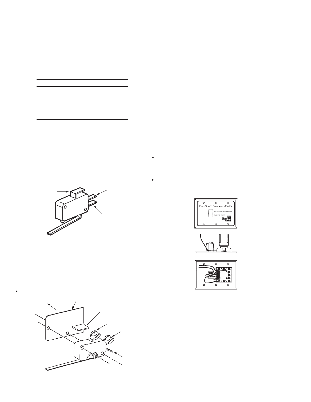
Switches are available in kits: One Switch Kit (Part No. 551154);
Two Switch Kit (Part No. 551155); Three Switch Kit (Part No.
551156), and Four Switch Kit (Part No. 551157). Mounting hardware and 12 in. wire assemblies are provided with each kit. Each
switch has a set of single-pole, double-throw contacts rated:
UL/cUL/CSa Rating ENEC Rating
250 VaC, 21a Resistive IE4T105µ approved
250 VaC, 2 HP 250V, 21a Resistive
125 VaC, 1 HP 8a Motor Load
COMMON
(RED)
N.O.
(BLaCK)
See NFPa 72, “National Fire alarm Code,” Initiating Devices
section, for the correct method of wiring connection to the fire
alarm panel.
MODEL SM-120 SOLENOID MONITOR
The Model SM-120 Solenoid Monitor (Part No. 550302) is
used in conjunction with the Model ECH3-120 control head to
supervise the actuation and detection circuits. In the event of a
problem in the circuit, a light on the monitor goes out. Two sets
of NO/NC dry contacts are provided. The unit mounts directly to
a three-gang wall outlet box. The Model SM-120 acts as a reset
relay when used with an electric gas valve. Electric gas valve
wiring instructions are provided in the installation section of this
manual. See Figure 2-29.
Note: When utilizing electric detection, it is recommended that
the Model ECH3-24 electric control head be used with either
the aUTOPULSE 542R Control Panel (Part No. 433607) or
the aUTOPULSE Z-10 Control Panel (Part No. 430525). If the
ECH3-120 control head is to be utilized, it must be used with
Solenoid Monitor Model SM-120 (Part No. 550302), along with
a UL Listed 1a, 120VaC secondary power supply (by others) in
accordance with NFPa 17a, NFPa 96, and the local authority
Having Jurisdiction (aHJ). When the Solenoid Monitor Model
SM-120 (Part No. 550302) is used as a reset relay with an electric gas valve, a UL Listed 1a, 120VaC secondary power supply
is not required.
N.C.
(BROWN)
FIguRE 2-27
001612
The alarm Initiating Switch Kit (Part No. 550077) can be fieldmounted within the control head. This switch must be used to
close a supervised circuit to the building main fire alarm panel
when the control head actuates. This action will signal the fire
alarm panel that there was a system actuation in the kitchen
area. The switch kit contains all necessary mounting components along with a mounting instruction sheet. The switch is
rated 50 ma, 28VDC. See Figure 2-28.
TOWaRD REaR OF
CONTROL HEaD
SPaCER
WHEN SPaCER aND
SWITCH aRE PROPERLY
MOUNTED, THIS DIVIDER
MUST BE BETWEEN THE
N.O. aND N.C. TERMINaLS
COM
N.O.
N.C.
FIguRE 2-29
002860PC
PIPE AND FITTINgS
Pipe and fittings must be furnished by the installer. Schedule 40
stainless steel, chrome plated, or black pipe and fittings must be
used. galvanized pipe and fittings are not to be used.
FIguRE 2-28
004890
Page 23
KITCHEN KNIGHT II Restaurant Fire Suppression Manual
AgENT DISTRIBuTION HOSE AND RESTRAININg CABLE
KIT
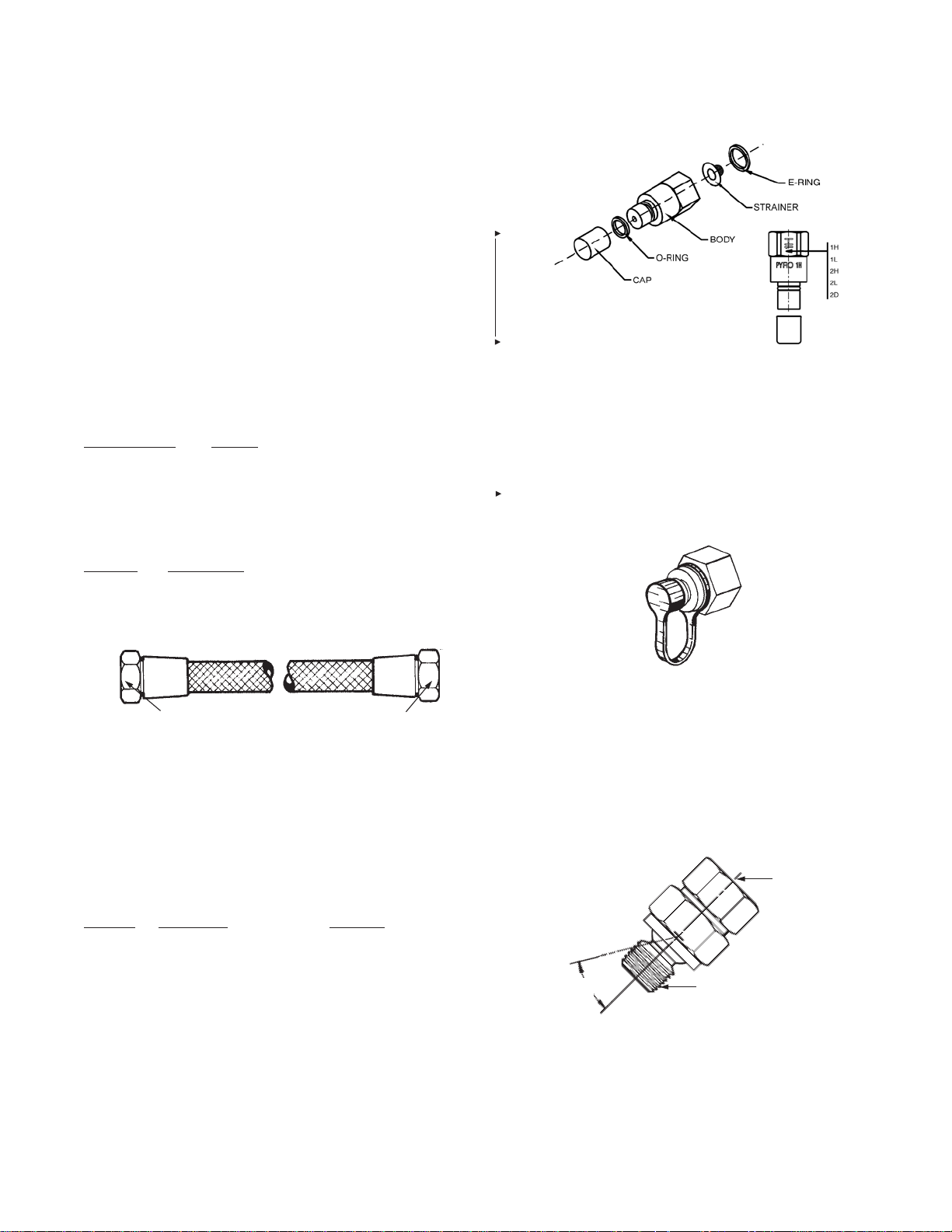
The agent Distribution Hose and Restraining Cable Kit (Part No.
435982) consists of a 5 ft (1.5 m) long agent Distribution Hose,
a 3 ft (0.9 m) long Restraining Cable, and a Restraining Cable
Hardware Package. The agent Distribution Hose can be utilized
with castered appliances found in commercial kitchens. The
hose allows for movement of the appliance for cleaning without
having to disconnect any fire suppression system discharge
piping.
STAINLESS STEEL ACTuATION HOSE
The Stainless Steel actuation Hose is used to connect the actuation line compression tees and can also be connected end to
end. The hose has the same thread, 7/16-20, as the fittings. See
Figure 2-30.
Hose Part No. Length
417582 8 in. (203 mm)
31809 16 in. (406 mm)
32336 24 in. (610 mm)
430815 42 in. (1067 mm)
Fitting
Part No. Description
31810 Male Elbow (7/16-20 x 1/4 in. NPT)
31811 Male Tee (7/16-20 x 7/16-20 x 1/4 in. NPT)
32338 Male Straight Connector (7/16-20 x 1/4 in. NPT)
SECTION 2 – COMPONENTS
UL EX3830 ULC EX3830
2014-NOV-10 REV. 06 PagE 2-11
FIguRE 2-31
006171PC
RuBBER BLOW-OFF CAPS
The Rubber Blow-Off Cap helps keep the orifice of the nozzle
free of grease or other substances that could interfere with
agent distribution. a retaining strap attaches the blow-off cap
to the nozzle. See Figure 2-32. Rubber Blow-Off Caps must
be ordered as a Shipping assembly (Part No. 550016) which
contains 12 blow-off caps.
7/16-207/16-20
FIguRE 2-30
000433
NOZZLES
Nozzles have been developed for appliance, plenum, and duct
applications. all nozzles have a specific flow point value and
are supplied with metal blow-off caps to prevent clogging. Each
nozzle is stamped with the model number. See Figure 2-31.
application limitations are provided in the design section of this
manual.
Part No. Description Flow No.
551029 1H Nozzles, 10-pack 1
551026 1L Nozzles, 10-pack 1
551028 2H Nozzles, 10-pack 2
551027 2L Nozzles, 10-pack 2
551038 2D Nozzles, 10-pack 2
FIguRE 2-32
000009
SWIVEL ADAPTOR
The Swivel adaptor (Part No. 418569) consists of a swivel
nut, swivel body, and swivel ball. all are chrome-plated. The
swivel adaptor allows the nozzle to be rotated approximately
30° in all directions. Swivel adaptors can be ordered as a single
Swivel adaptor or Swivel adaptor Shipping assembly (Part No.
423572) which contains 25 swivel adaptors. See Figure 2-33.
3/8 – 18 NPT
FEMaLE THREaD
30°
ROTaTION
3/8 – 18 NPT
MaLE THREaD
FIguRE 2-33
000003
Page 24
SECTION 2 – COMPONENTS
UL EX3830 ULC EX3830
PagE 2-12 REV. 06 2014-NOV-10
NOZZLE AIMINg DEVICE
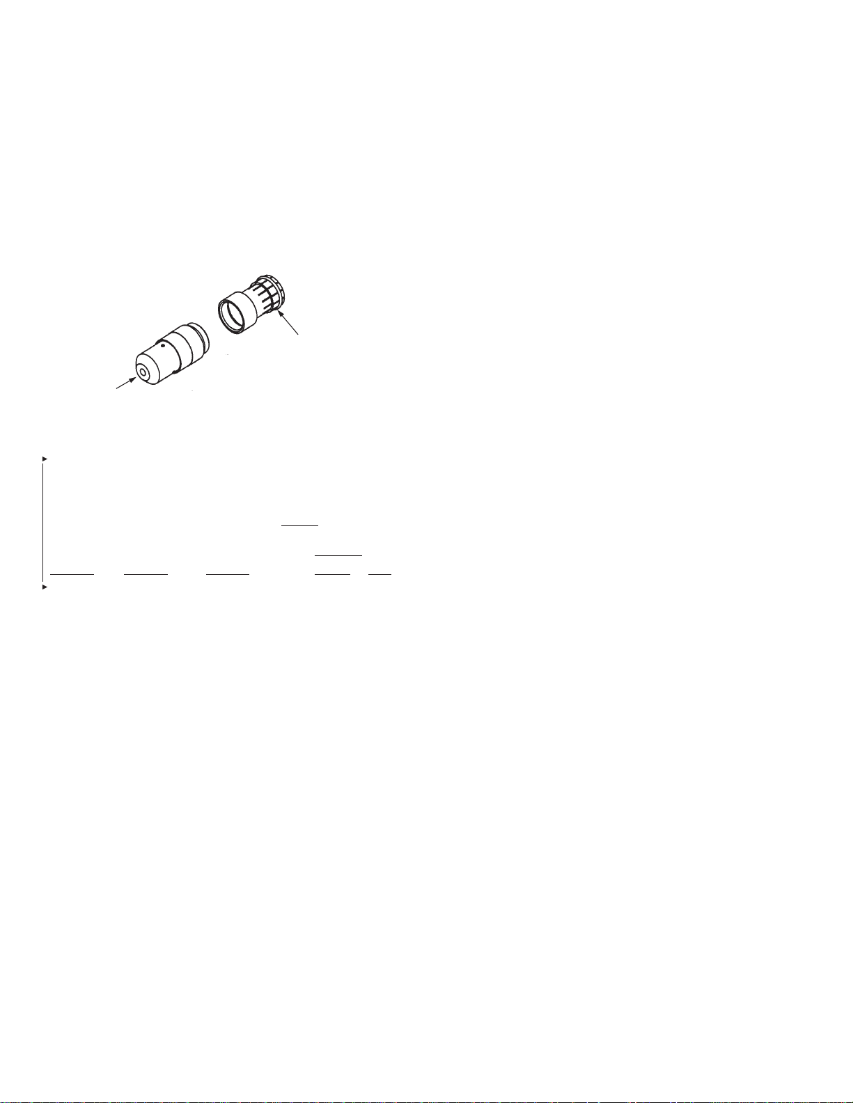
The Nozzle aiming Device (Part No. 551265) is required to
properly aim each nozzle to the correct aiming point. The device
clamps to the nozzle and emits a small laser light that reflects on
the surface that it is aiming at. The nozzle can then be rotated
to point at a predetermined aiming point and then tightened to
hold that angle. The aiming device requires an adaptor (Part No.
550926) to attach it to the nozzle. The adaptor must be ordered
separately. See Figure 2-34.
aDaPTOR (ORDER
SEPaRaTELY)
NOZZLE
aIMINg
DEVICE
FIguRE 2-34
006520
KITCHEN KNIGHT II Restaurant Fire Suppression Manual
HORN/STROBE ASSEMBLY
The Horn/Strobe assembly (Part No. 434528) includes the
following specifications:
Strobe
Regulated Voltage Maximum RMS Candela Per
Voltage Range Current UL 1638
(VRMS) (VRMS) (aMPS) —35C 25C
120 96-132 .070 7.5cd 15cd
Page 25

KITCHEN KNIGHT II Restaurant Fire Suppression Manual
SECTION 2 – COMPONENTS
UL EX3830 ULC EX3830
2014-NOV-10 REV. 06 PagE 2-13
MODEL
NO. DESCRIPTION PART NO.
PCL-160 1.6 gaLLON CYLINDER aSSEMBLY 553163
PCL-300 3.0 gaLLON CYLINDER aSSEMBLY 551194
PCL-460 4.6 gaLLON CYLINDER aSSEMBLY 551193
PCL-600 6.0 gaLLON CYLINDER aSSEMBLY 551196
PaC-10 PNEUMaTIC aCTUaTINg CYLINDER 550104
PCL-300 CaNaDIaN – 3.0 gaLLON 551195
CYLINDER aSSEMBLY
PCL-460 CaNaDIaN – 4.6 gaLLON 551192
CYLINDER aSSEMBLY
PCL-600 CaNaDIaN – 6.0 gaLLON 551197
CYLINDER aSSEMBLY
PaC-10 CaNaDIaN – PNEUMaTIC 551125
aCTUaTINg CYLINDER
MB-1 MOUNTINg BRaCKET (FOR PCL-600) 550053
MB-15 MOUNTINg BRaCKET 550054
(FOR PCL-160/300/460)
MB-P2 MOUNTINg BRaCKET 550853
(FOR MCH3 ECH3-24/120)
MCH3 MECHaNICaL CONTROL HEaD 551200
NMCH3 MECHaNICaL CONTROL HEaD 551203
(NO HaNDLE)
EN-MCU3 ENCLOSURE (FOR PRIMaRY 551208
CYLINDER)
EN-S ENCLOSURE (FOR SECONDaRY 550966
CYLINDER)
ECH3-24 24VDC ELECTRICaL 551201
CONTROL HEaD
ECH3-120 120VaC ELECTRICaL 551202
CONTROL HEaD
– – – 8 IN. (203 mm) SS aCTUaTION HOSE 417582
– – – 16 IN. (406 mm) SS aCTUaTION HOSE 31809
– – – 24 IN. (610 mm) SS aCTUaTION HOSE 32336
– – – 42 IN. (1067 mm) SS 430815
aCTUaTION HOSE
– – – MaLE ELBOW 31810
– – – MaLE TEE 31811
– – – MaLE STRaIgHT CONNECTOR 32338
1H WET NOZZLE (PaCK OF 10) 551029
1L WET NOZZLE (PaCK OF 10) 551026
2H WET NOZZLE (PaCK OF 10) 551028
2L WET NOZZLE (PaCK OF 10) 551027
2D WET NOZZLE (PaCK OF 10) 551038
– – – SWIVEL aDaPTOR (PaCK OF 25) 423572
– – – RUBBER BLOW-OFF CaPS 550016
(PaCK OF 12)
RPS-M REMOTE MECHaNICaL 551074
PULL STaTION
MODEL
NO. DESCRIPTION PART NO.
FLK-1 10 IN. (254 mm) FUSIBLE LINK
BRaCKET KIT 550131
FLK-1a 8 IN. (203 mm) FUSIBLE LINK
BRaCKET KIT 550132
FLH-25 25 x FUSIBLE LINK HaNgER 550876
– – – FUSIBLE LINK – 165 °F (74 °C) (10) 439227
– – – FUSIBLE LINK – 212 °F (100 °C) (10) 439228
– – – FUSIBLE LINK – 280 °F (138 °C) (10) 439229
– – – FUSIBLE LINK – 360 °F (182 °C) (10) 439230
– – – FUSIBLE LINK – 450 °F (232 °C) (10) 439231
– – – FUSIBLE LINK – 500 °F (260 °C) (25) 439232
SM-120 120VaC SOLENOID MONITOR 550302
TD-225 THERMaL DETECTOR 225 °F (107 °C) 13976
TD-325 THERMaL DETECTOR 325 °F (163 °C) 13975
TD-450 THERMaL DETECTOR 450 °F (232 °C) 13974
TD-600 THERMaL DETECTOR 600 °F (316 °C) 13971
EgVSO-75 ELECTRIC gaS SHUT-OFF 13707
VaLVE 3/4 IN.
EgVSO-100 ELECTRIC gaS SHUT-OFF 13708
VaLVE 1 IN.
EgVSO-125 ELECTRIC gaS SHUT-OFF 550360
VaLVE 1-1/4 IN.
EgVSO-150 ELECTRIC gaS SHUT-OFF 13709
VaLVE 1-1/2 IN.
EgVSO-200 ELECTRIC gaS SHUT-OFF 13710
VaLVE 2 IN.
EgVSO-250 ELECTRIC gaS SHUT-OFF 550363
VaLVE 2-1/2 IN.
EgVSO-300 ELECTRIC gaS SHUT-OFF 17643
VaLVE 3 IN.
gV-75 MECHaNICaL gaS SHUT-OFF 550593
VaLVE 3/4 IN.
gV-100 MECHaNICaL gaS SHUT-OFF 550594
VaLVE 1 IN.
gV-125 MECHaNICaL gaS SHUT-OFF 550595
VaLVE 1-1/4 IN.
gV-150 MECHaNICaL gaS SHUT-OFF 550596
VaLVE 1-1/2 IN.
gV-200 MECHaNICaL gaS SHUT-OFF 551049
VaLVE 2 IN.
gV-250 MECHaNICaL gaS SHUT-OFF 550185
VaLVE 2-1/2 IN.
gV-300 MECHaNICaL gaS SHUT-OFF 550186
VaLVE 3 IN.
MS-SPDT ELECTRICaL SWITCH – 551154
SINgLE POLE DOUBLE THROW
MS-DPDT ELECTRICaL SWITCH – 551155
DOUBLE POLE DOUBLE THROW
Page 26

SECTION 2 – COMPONENTS
UL EX3830 ULC EX3830
PagE 2-14 REV. 06 2014-NOV-10
KITCHEN KNIGHT II Restaurant Fire Suppression Manual
MODEL
NO. DESCRIPTION PART NO.
MS-3PDT ELECTRICaL SWITCH – 3 POLE 551156
DOUBLE THROW
MS-4PDT ELECTRICaL SWITCH – 4 POLE 551157
DOUBLE THROW
– – – aLaRM INITIaTINg SWITCH 550077
-6 6 x CO2 CaRTRIDgE (16 gM) 551059
CO
2
– – – O-RINg, aCTUaTOR aSSEMBLY 55531
CBP-1 COMPRESSION BEaRINg 423250
CORNER PULLEY
SBP- 1 SCREW BEaRINg CORNER PULLEY 415670
WBP-1 WEaTHER PROOF BEaRINg 550982
CORNER PULLEY
TP-1 TEE PULLEY 427929
– – – WET VaLVE CaP 550831
– – – CONICaL SPRINg (WET VaLVE) 550705
– – – PRESSURE gaUgE (WET VaLVE) 551236
– – – PRESSURE REgULaTOR aSSEMBLY 550985
– – – WET VaLVE REBUILDINg KIT 550698
– – – PRESSURE REgULaTOR 551061
REBUILD KIT
VT-1 VaLVE TOOL (WET VaLVE) 550788
– – – NECK O-RINg (WET VaLVE) 550716
– – – PISTON (WET VaLVE) 550707
– – – PISTON O-RINg (WET VaLVE) 550715
– – – VaLVE CaP O-RINg (WET VaLVE) 550714
RL-160 1.6 gaLLON RECHaRgE 553176
RL-300 3.0 gaLLON RECHaRgE 551188
PCL-300T TEST TaNK 551024
PCL-460T TEST TaNK 550902
PCL-600T TEST TaNK 550901
– – – RUBBER BLOW-OFF CaP 550016
– – – 10 x WET NOZZLE CaP 551528
– – – 10 x WET NOZZLE STRaINER 551529
– – – 10 x WET NOZZLE O-RINg 551530
– – – VaLVE STEM O-RINg 550028
– – – COMPLETE WET VaLVE aSSEMBLY 551175
PCL-aK RECHaRgE aDaPTOR KIT 551240
– – – MEaSURINg STICK 551039
– – – STaINLESS STEEL WIRE ROPE,
50 FT (15.2 m) 15821
– – – STaINLESS STEEL WIRE ROPE,
500 FT (152.4 m) 79653
WC-100 OVaL SLEEVE CRIMPS 550122
(100 PER PaCKagE)
– – – STOP SLEEVES (PaCK OF 10) 24919
MODEL
NO. DESCRIPTION PART NO.
– – – FLUSHINg CONCENTRaTE
(32 OZ (907.2 g)) 553568
– – – FLEXIBLE CONDUIT – 500 FT (152.4 m) 434525
– – – FLEXIBLE CONDUIT – 500 FT (152.4 m) 435959
aND WIRE ROPE – 500 FT (152.4 m)
– – – PRE-FED FLEXIBLE CONDUIT 439104
aSSEMBLY – 50 FT (15.2 m)
– – – FLEXIBLE CONDUIT STRaIN RELIEF 435979
(50 PaCK)
– – – FLEXIBLE CONDUIT INSERT (50 PaCK) 434347
– – – CONDUIT OFFSET (6-PaCK) 436063
– – – P-CLIP (50-PaCK) 436150
– – – COMPRESSION UNION, 1/2 IN. 79827
– – – COMPRESSION CONNECTOR, 1/2 IN. 55813
– – – HENNY PENNY NOZZLE KIT 553389
– – – COMPRESSION-SEaL aDaPTOR 79153
– – – agENT DISTRIBUTION HOSE aND 435982
TETHER KIT
–
– – HYDROTEST aDaPTOR 552181
– – – HORN/STROBE aSSEMBLY 434528
Page 27
KITCHEN KNIGHT II Restaurant Fire Suppression Manual
SECTION 3 – SYSTEM DESIGN
UL EX3830 ULC EX3830
2014-NOV-10 REV. 06 PagE 3-1
GENERAL
The KITCHEN KNIgHT II Restaurant Fire Suppression System
may be used on a number of different types of restaurant
cooking appliances and hood and duct configurations. The
design information listed in this section deals with the limitations
and parameters of this pre-engineered system. Those individuals responsible for the design of the KITCHEN KNIgHT II
system must be trained and hold a current PYRO-CHEM certificate in a KITCHEN KNIgHT II training program.
NOZZLE COVERAGE AND PLACEMENT
This section will provide guidelines for determining nozzle
type, positioning, and quantity for duct, plenum, and appliance
protection.
Duct Protection
It is not required that the fan be shut down or the exhaust duct
be dampered for the system to operate properly.
all duct protection is UL Listed without limitation of maximum
duct length (unlimited length). This includes all varieties of
ductworks both horizontal and vertical including ducts that run at
angles to the horizontal and ducts with directional bends.
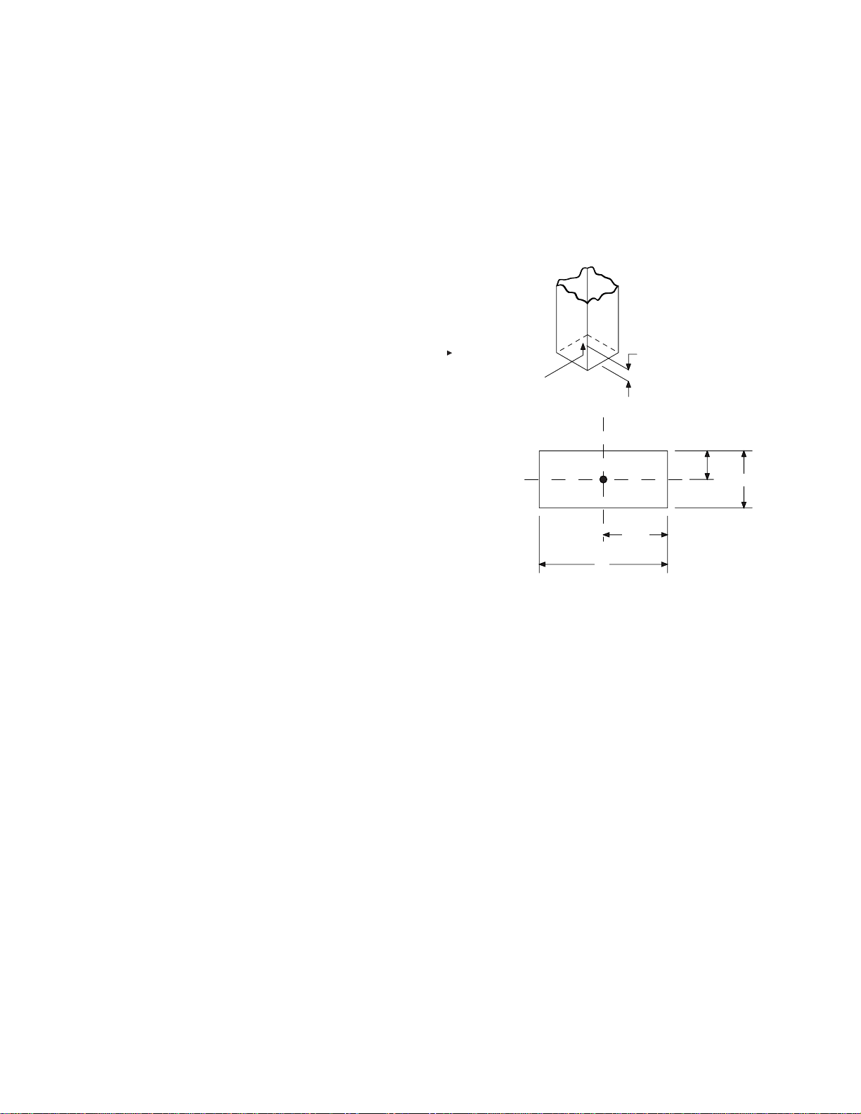
Duct protection requires that a nozzle be positioned to discharge
into the duct. Two nozzles are available for duct protection.
The Model IL Duct Nozzle (Part No. 551026) is a one flow nozzle.
a single IL nozzle is capable of protecting square or rectangular
ducts with a maximum perimeter of 50 in. (1270 mm) (maximum
side of 16 3/4 in. (425 mm)), with the diagonal being a maximum
of 18 3/4 in. (476 mm). It can also protect a round duct with a
maximum diameter of 16 in. (406 mm).
The Model 2D Duct Nozzle (Part No. 551038) is a two flow
nozzle. a single 2D nozzle is capable of protecting square
or rectangular ducts with a maximum perimeter of 100 in.
(2540 mm), with the diagonal being a maximum of 37 3/8 in.
(949 mm). It can also protect a round duct with a maximum
diameter of 31 7/8 in. (809 mm).
When two 2D duct nozzles are used to protect a single duct,
the cross sectional area of the duct must be divided into two
equal symmetrical areas. The nozzle must then be installed on
the centerline of the area it protects and aimed directly into the
duct opening.
The nozzle(s) must be installed on the centerline of the duct,
with the tip located 0 to 6 in. (0 to 152 mm) into the opening, and
aimed directly into the duct opening. See Figure 3-1.
In installations where a UL listed damper assembly is employed,
the duct nozzle can be installed beyond the 6 in. (152 mm)
maximum, to a point just beyond the damper assembly that will
not interfere with the damper. Exceeding the maximum of 6 in.
(152 mm) in this way will not void the UL listing of the system.
0-6 IN. (0-152 mm)
INTO DUCT
IL OR 2D
NOzzLE
1/2 W
1/2 L
L
W
006172PC
FIGuRE 3-1
Page 28
SECTION 3 – SYSTEM DESIGN
UL EX3830 ULC EX3830
PagE 3-2 REV. 06 2014-NOV-10
KITCHEN KNIGHT II Restaurant Fire Suppression Manual
NOZZLE COVERAGE AND PLACEMENT (Continued)
Duct Protection (Continued)
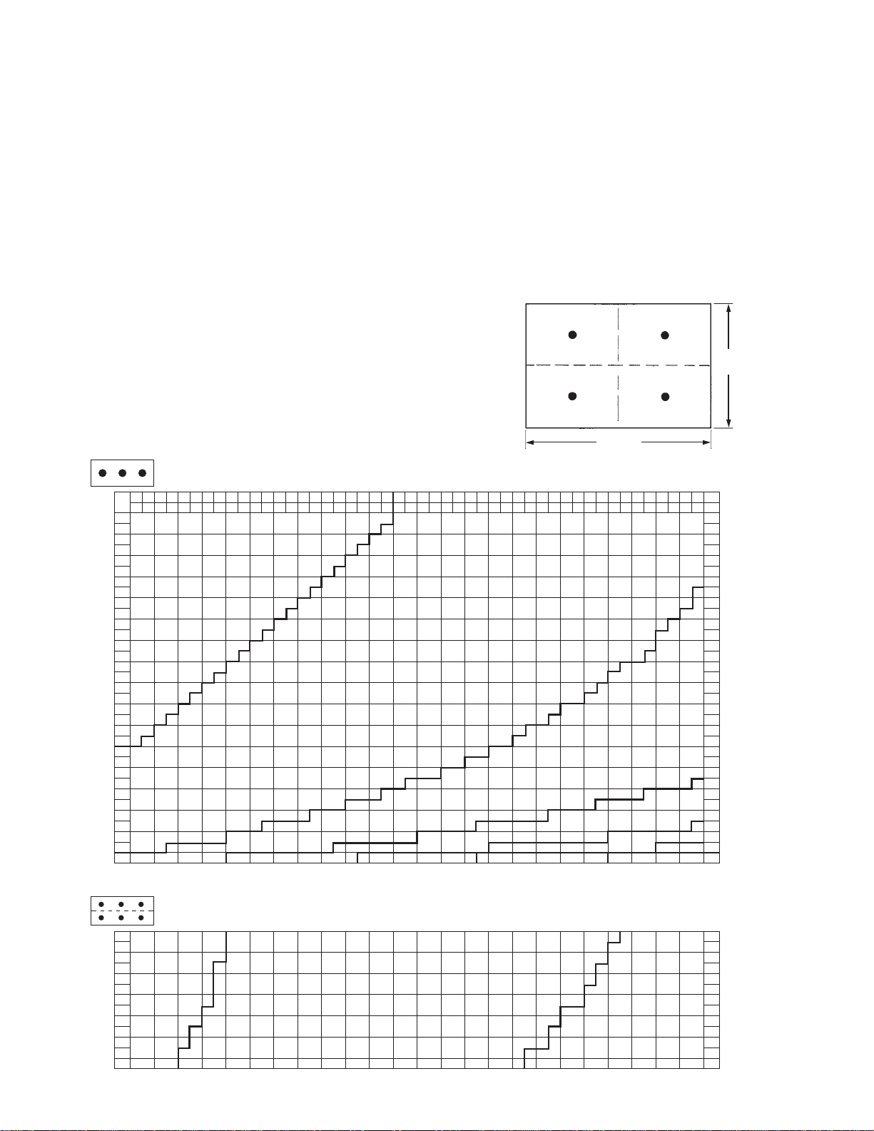
Modularizing Ducts –
DUCT SIzES gREaTER THaN 100 IN. (2540 mm) PERIMETER
• Ducts over 100 in. perimeter must be modularized using 2D
nozzles (Part No. 551038)
• No round duct option available
• Follow the design chart to determine maximum module size
for each 2D nozzle
• When determining number of nozzles required, it is sometimes
an advantage to check the chart using the shortest side as
Side “a” and then recheck it using the longest side as Side
“a.” This comparison may reveal a need for a lesser quantity
of nozzles one way versus the other way.
When working with Chart 3-1, the quantity of nozzles determined
must be equally divided within the duct area.
CHART 3-1
SIDE
CHART 3-2
B
A
26 28 30 32 34 36 38 40 42 44 46 48 50 52 54 56 58 60 62 64 66 68 70 7227 29 31 33 35 37 39 41 43 45 47 49 51 53 55 57 59 61 63 65 67 69 71
25
64 66 69 71 74 76 79 81 84 86 89 91 94 97 99
4
5
6
7
8
9
10
11
12
13
14
15
16
17
18
19
“A”
20
21
22
23
24
25
26
27
28
29
30
31
32
33
34
35
36
in. cm
B
1
102 104 107 109 112114 11 7119 122124 127130 132135 137 140 142 145 147 150 152 155 157 160 163 165 168 170173 175 178 180183
SIDE “B”
When working with Chart 3-2, one half of the quantity of nozzles
determined must be equally positioned in the top half of the area
of the duct and the remaining half of the nozzles must be positioned in the bottom half of the duct area.
Example: The duct to be protected has a Side “a” of 40 in. (1016
mm) and a Side “B” of 60 in. (1524 mm). Referring to the design
chart, this duct requires 4 nozzles. One half of 4 = 2. Therefore,
2 nozzles must be equally positioned in each of the two duct
areas. See Figure 3-2.
SIDE “B”
60 IN.
(1524 mm)
40 IN.
(1016 mm)
SIDE
“A”
20 IN.
(508 mm)
20 IN.
(508 mm)
30 IN. (762 mm) 30 IN. (762 mm)
FIGuRE 3-2
in.
in.
cm
cm
10
13
15
18
FIGuRE 3-1b
20
23
25
28
30
33
36
38
2
3
4
5
765
41
43
46
48
51
53
56
58
61
64
66
69
71
74
76
79
81
84
86
89
6
91
006523
A
36
37
38
39
40
41
42
43
44
45
46
47
48
in. cm
NOTE: NOzzLE qUaNTITIES LISTED IN CHaRT 3-2 MUST BE EqUaLLY DIVIDED INTO EaCH OF THE TWO DUCT MODULES.
2
4
91
94
97
99
102
104
6
107
109
112
114
117
119
122
006522
Page 29
KITCHEN KNIGHT II Restaurant Fire Suppression Manual
SECTION 3 – SYSTEM DESIGN
UL EX3830 ULC EX3830
2014-NOV-10 REV. 06 PagE 3-3
NOZZLE COVERAGE AND PLACEMENT (Continued)
Duct Protection (Continued)
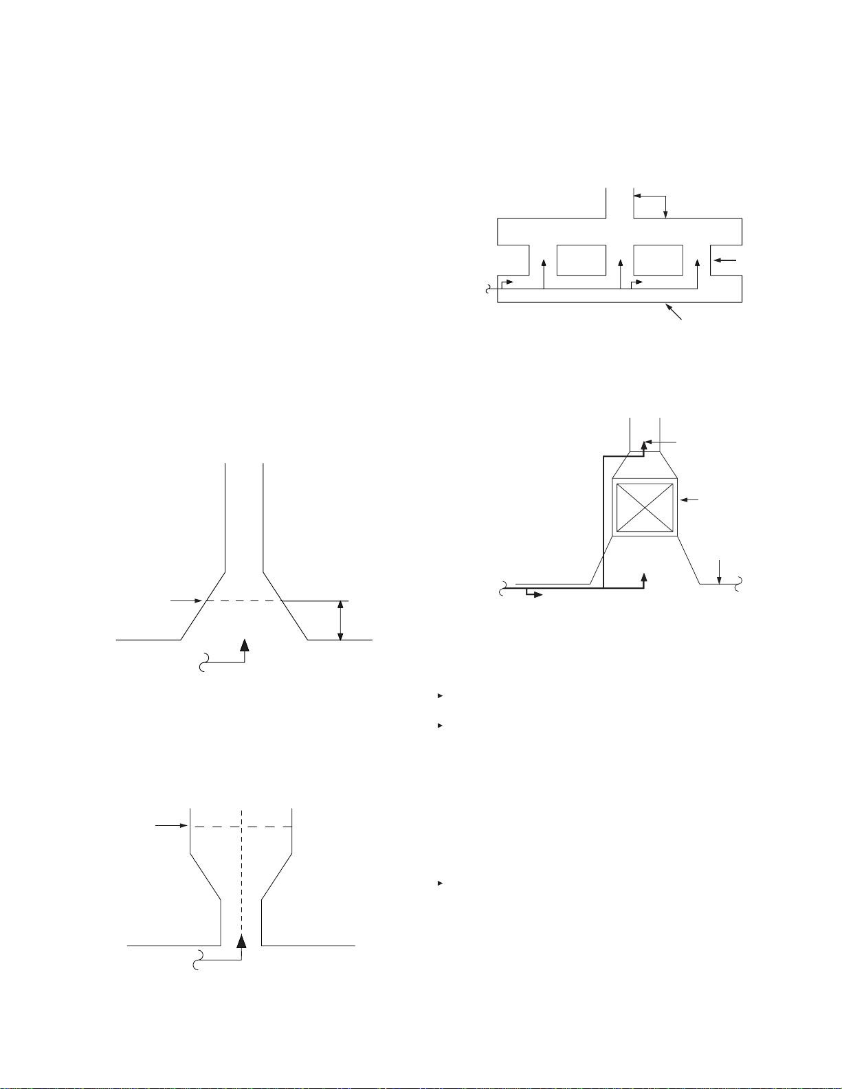
Transition Ducts – The protection of non-standard ducts should
be reviewed by the authority having jurisdiction. PYRO-CHEM
KITCHEN KNIgHT II recommends that transition ducts be
protected as follows:
a. Transition ducts – larger to smaller
In cases where the duct/plenum interface opening is larger
than the final exhaust duct, measure the perimeter/diameter
of the duct halfway between the largest and smallest section
(or the average perimeter/diameter). The nozzle is to be
located within 0 to 6 in. (0 to 152 mm) of the duct/plenum
interface (not at the point where the measurement was
taken), centered under the final exhaust duct opening. See
Figure 3-3.
Note: Nozzles to protect ducts with a transition that is
more than 4 ft (1.2 m) in height, will be required to be positioned in the opening of the transition from the hood 2 in. to
8 in. (51 mm to 203 mm) into the opening using standard
duct nozzle design parameters.
c. Multiple risers
In cases of multiple rises, each riser is protected as an indi-
vidual duct. See Figure 3-5.
DUCT
DUCT
006175PC
PLENUM
FIGuRE 3-5
Electrostatic Precipitator – Ducts utilizing electrostatic precip-
itators must be protected above and below the unit. Standard
duct nozzles are used in this application. See Figure 3-6.
2D NOzzLE
PRECIPITaTOR
PERIMETER
MEaSUREMENT
1/2 WaY INTO
TRaNSITION
006173PC
FIGuRE 3-3
b. Transition ducts – smaller to larger
In cases where the duct/plenum interface opening is smaller
than the final exhaust duct, measure the perimeter/diameter of the final exhaust duct. The nozzle(s) is to be located
within 0 to 6 in. (0 to 152 mm) of the duct/plenum interface,
centered in the opening. See Figure 3-4.
PERIMETER
MEaSUREMENT
2D NOzzLE
PLENUM
006176PC
FIGuRE 3-6
Plenum Protection
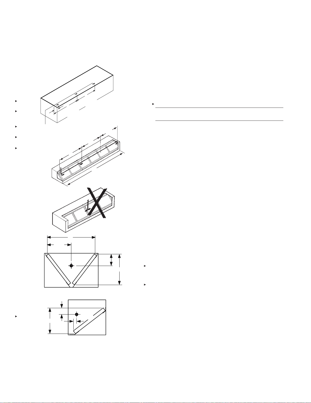
The Model 1H nozzle (Part No. 551029) is a one flow nozzle
used for plenum protection. a single 1H nozzle can protect a
plenum (with single or V-bank filters) 10 ft (3.0 m) long by 4 ft
(1.2 m) wide. Dividing the length into sections equal to or less
than 10 ft (3.0 m) in length and positioning a nozzle at the start
of each section can be done to protect longer plenums.
On V-bank plenums, the nozzle(s) must be located at the center
of the V-bank width, 1/3 of the vertical height of the filters. On
single filter bank plenums, the nozzle must be located 2 in. (50
mm) from the back edge of the filter, 1/3 down from the vertical
height. For either application, the nozzle must be located within
6 in. (152 mm) of the end of the plenum (or module) and aimed
directly down the length of the plenum. The nozzles may point
in the opposite directions as long as the entire plenum area is
protected, and the 10 ft (3.0 m) limitation is not exceeded. See
Figure 3-7.
006174PC
FIGuRE 3-4
Page 30
SECTION 3 – SYSTEM DESIGN
UL EX3830 ULC EX3830
PagE 3-4 REV. 06 2014-NOV-10
KITCHEN KNIGHT II Restaurant Fire Suppression Manual
NOZZLE COVERAGE AND PLACEMENT (Continued)
Plenum Protection (Continued)
000207
10 FT (3.0 m)
MaXIMUM
1/2 W
1/3 H
H
IN.-6 IN. (0 mm-152 mm)
0
10 FT
(3.0 m)
MaX.
10 FT (3.0 m)
MaXIMUM
W
V BANk
2 IN.
(50
SINGLE BANk
10 FT
(3.0 m)
MaX.
mm
006177aPC
10 FT (3.0 m)
MaXIMUM
30 FT
(9.1 m)
INCORRECT
1/3 H
)
000208
H
006177bPC
FIGuRE 3-7
Appliance Protection
Note: When protecting appliances which are larger than single
nozzle coverage, multiple nozzles can be used.
Larger appliances can be divided into several modules, each
equal to or smaller than single nozzle coverage. Exception:
Fryers must not exceed a maximum of 864 in.2 (55741 mm2).
For modularizing fryers, refer to “FRYER – MULTIPLE NOzzLE
PROTECTION.”
TABLE 3-1: APPLIANCE PROTECTION
Appliance Maximum Cooking
Type Hazard Area per Nozzle
Fryer Without 19 in. x 19 1/2 in. maximum
Drip Board (482 mm x 495 mm)
Fryer With 18 in. x 27 3/4 in. (457 mm x 704 mm)
Drip Board maximum; 19 1/2 in. x 25 3/8 in.
(495 mm x 644 mm) maximum
2
Small Range Maximum area of 336 in.
(21677 mm2) with
the longest side to be a maximum of 28 in.
(711 mm)
Large Range Maximum area of 784 in.
2
(50580 mm2) with
the longest side to be a maximum of 28 in.
(711 mm)
Small Wok 24 in. (609 mm) diameter x 6 in. (152 mm)
deep maximum
Large Wok 30 in. diameter x 8 in. deep
(762 mm x 203 mm) maximum
2
Small Maximum area of 1080 in. (69677 mm
)
griddle with the longest side to be a maximum of
36 in. (914 mm)
Large Maximum area of 1440 in.
2
(92903 mm2)
griddle with the longest side to be a maximum of
48 in. (1219 mm)
gas Radiant/ Maximum area of 624 in.
2
(40257 mm2)
Electric with the longest side to be a maximum of
Char-Broiler 26 in. (660 mm)
gas Radiant/ Maximum area of 864 in.
2
(55741 mm2)
Electric with the longest side to be a maximum of
Char-Broiler 36 in. (914 mm)
Lava Rock Maximum area of 624 in.
2
(40257 mm2)
Char-Broiler with the longest side to be a maximum of
26 in. (660 mm)
Natural Maximum area of 480 in.
2
(30967 mm2)
Charcoal with the longest side to be a maximum of
Broiler 24 in. (609 mm)
Mesquite Maximum area of 480 in.
2
(30967 mm2)
Char-Broiler with the longest to be a maximum of
24 in. (609 mm)
Upright/ Maximum area of 1064 in.
2
(68645 mm2)
Salamander with the longest side to be a maximum of
Broiler 36 in. (914 mm)
Chain Broiler Maximum area of 1026 in.
2
(66193 mm2)
with the longest side to be a maximum of
38 in. (965 mm)
Page 31
KITCHEN KNIGHT II Restaurant Fire Suppression Manual
SECTION 3 – SYSTEM DESIGN
UL EX3830 ULC EX3830
2014-NOV-10 REV. 06 PagE 3-5
NOZZLE COVERAGE AND PLACEMENT (Continued)
Appliance Protection (Continued)
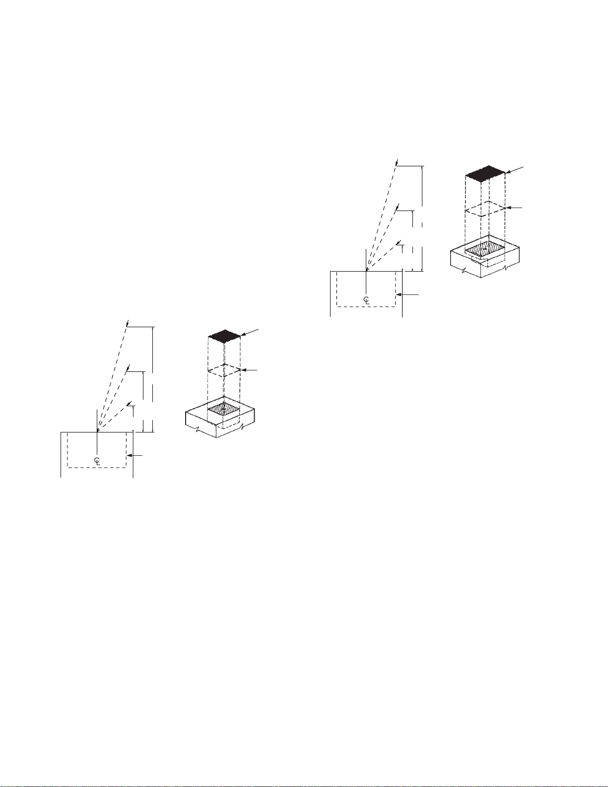
1. Fryers without Drip Board (19 in. x 19 1/2 in. maximum)
(482 mm x 495 mm)
Two nozzles are available for fryer protection: High proxim-
ity and low proximity.
The Model 2H nozzle is used for high proximity fryer protec-
tion. This nozzle is a two flow nozzle. The nozzle must be
located anywhere within the perimeter of the hazard area,
24 in. to 48 in. (610 mm to 1219 mm) above the cooking
surface of the appliance and aimed at the center of the
cooking area. See Figure 3-8.
The Model 2L nozzle is used for low proximity fryer protec-
tion. This nozzle is a two flow nozzle. The nozzle must be
located anywhere on the perimeter of the hazard area, 13
in. to 24 in. (330 mm to 609 mm) above the cooking surface
of the appliance and aimed at the center of the cooking
area. See Figure 3-8.
OF
HazaRD
aREa
2H
2H, 2L
13 IN.
(330 mm)
48 IN. (1219 mm)
2L
24 IN.
(609 mm)
006178PC
EDgE OF
HazaRD
aREa
FRYERS wITHOuT
DRIPBOARDS
006229PC
HIgH
PROXIMITY
NOzzLE
LOCaTED
aNYWHERE
wITHIN THE
PERIMETER
LOW
PROXIMITY
NOzzLE
LOCaTED
aNYWHERE
ON THE
PERIMETER
FIGuRE 3-8
1a. Fryers with Drip Board
The maximum single nozzle protection dimensions depend
on the dimensions of the fry pot only.
For fry pots with maximum dimensions of 18 in. (457 mm)
2
on the longest side and 324 in.
(20903 mm2) max. area,
use overall dimensions of 27 3/4 in. (704 mm) on the
longest side and 500 in.
2
(32258 mm2) max. area.
For fry pots with maximum dimensions exceeding 18 in. x
2
324 in.
in. (495 mm) on the longest side and 371 in.
(457 mm x 20903 mm2), but no greater than 19 1/2
2
(23935 mm2)
max area, use overall dimensions of 25 3/8 in. (644 mm)
on the longest side and 495 in.
2
(31935 mm2) area.
Two nozzles are available for fryer protection: High proxim-
ity and low proximity.
The Model 2H Nozzle (Part No. 551028) is used for high
proximity fryer protection. This nozzle is a two flow nozzle.
The nozzle must be located anywhere within the perime-
ter of the hazard area, 24 in. to 48 in. (610 mm to 1219 mm)
above the cooking surface of the appliance and aimed at the
center of the cooking area. See Figure 3-9.
The Model 2L nozzle is used for low proximity fryer protection.
This nozzle is a two flow nozzle. The nozzle must be located
anywhere on the perimeter of the hazard area, 13 in. to 24 in.
(330 mm to 609 mm) above the cooking surface of the appliance
and aimed at the center of the cooking area. See Figure 3-9.
006230PC
HIgH
PROXIMITY
NOzzLE
LOCaTED
aNYWHERE
wITHIN THE
PERIMETER
LOW
PROXIMITY
NOzzLE
LOCaTED
aNYWHERE
ON THE
PERIMETER
OF
HazaRD
aREa
2H
2H, 2L
2L
13 IN.
(330 mm)
48 IN.
(1219 mm)
24 IN.
(609 mm)
EDgE OF
HazaRD
aREa
006178PC
FRYERS wITH
DRIPBOARDS
FIGuRE 3-9
1.b Fryers – Multiple Nozzle Protection
Fryers exceeding the coverage of a single nozzle can
be divided into modules. Each module must not exceed
the maximum area allowed for a single nozzle. However,
when utilizing multiple nozzle protection, the longest side
allowed for a fryer with drip board can be used, regardless
of whether the fryer has a drip board or not.
The maximum size fryer that can be modularized is 864 in.
(55741 mm
2
).
2
Design requirements for multiple nozzle fryers are broken
down as follows:
1. If the fryer includes any dripboard areas, measure both
the internal length (front to back) and width of the frypot
portion. Then measure the internal length and width of
the overall hazard area including any dripboard areas.
Determine the area of both the frypot and the area of the
overall vat by multiplying corresponding length and width
dimensions.
2. Divide the frypot or overall vat into modules, each of
which can be protected by a single nozzle, based on the
maximum dimension and area coverage of the nozzle as
specified in Table 3-2: Design.
• If the module considered does not include any portion
of the dripboard, use only the maximum frypot area
and maximum dimension listed in Table 3-2: Design.
• If the module considered includes any dripboard areas,
use both the maximum frypot area and dimension
listed in Table 3-2: Design, and the maximum overall
area and dimension listed in Table 3-2: Design.
3. None of the maximum dimensions may be exceeded.
If either the maximum frypot or the overall sizes are
exceeded, the area divided into modules will need to
be redefined with the possibility of an additional nozzle.
Page 32
SECTION 3 – SYSTEM DESIGN
UL EX3830 ULC EX3830
PagE 3-6 REV. 06 2014-NOV-10
NOZZLE COVERAGE AND PLACEMENT (Continued)
Appliance Protection (Continued)
TABLE 3-2: DESIGN
Longest
Side
Option 1 27 3/4 in.
(704 mm)
Option 2 25 3/8 in.
(644 mm)
2. Small Range (336 in.
Vat
Coverage
2
324 in
(20903 mm2)
2
371 in
(23935 mm2)
2
(21677 mm2) maximum, 28 in.
Coverage
with Drip
2
500 in
(32258 mm
495 in2
(31935 mm2)
2
)
(711 mm) longest side maximum). Use this when nozzle is
center located.
Two nozzles are available for small range protection: High
proximity and low proximity.
The Model 1H Nozzle (Part No. 551029) is used for high
proximity small range protection. This nozzle is a one flow
nozzle. When using high proximity protection, the range
cannot be under a backshelf. This nozzle must be located
on the front/back centerline of the appliance, 40 in. to
50 in. (1016 mm to 1270 mm) above the cooking surface,
and aimed directly down within the “Nozzle Location area”
depending on the size of the hazard area. See Table 3-3:
Nozzle Flexibility Placement below. See Figure 3-10.
TABLE 3-3: NOZZLE FLEXIBILITY PLACEMENT (When
using nozzle flexibility, the maximum width that can be
protected is 12 in. (304 mm))
Length – L Width – W Front/Rear
in. (mm) in. (mm) in.* (mm)*
12 (304) 12 (304) 8 (203)
13 (330) 12 (304) 7 1/2 (190)
14 (355) 12 (304) 7 (177)
15 (381) 12 (304) 6 1/2 (165)
16 (406) 12 (304) 6 (152)
17 (431) 12 (304) 5 1/2 (139)
18 (457) 12 (304) 5 (127)
19 (482) 12 (304) 4 1/2 (114)
20 (508) 12 (304) 4 (101)
21 (533) 12 (304) 3 1/2 (88)
22 (558) 12 (304) 3 (76)
23 (584) 12 (304) 2 1/2 (63)
24 (609) 12 (304) 2 (50)
25 (635) 12 (304) 1 1/2 (38)
26 (660) 12 (304) 1 (25)
27 (685) 12 (304) 1/2 (12)
28 (711) 12 (304) 0 (0)
* Distance from centerline, either toward front or toward back, of hazard area,
starting from the reference point.
KITCHEN KNIGHT II Restaurant Fire Suppression Manual
REFERENCE
POINT
12 IN.
(304 mm)
MaXIMUM
WIDTH (W)
C
L
28 IN. (711 mm)
MaXIMUM LENgTH
(L)
1H
1H
006180PC
40 IN.
(1016 mm)
HIGH
PROXIMITY
50 IN.
(1270 mm)
NOzzLE
LOCaTION
aREa
FIGuRE 3-10
The Model 1L Nozzle (Part No. 551026) is used for low proximity small range protection. This nozzle is a one flow nozzle.
The range can be equipped either with or without a backshelf. Either type requires the same nozzle requirements. The
nozzle must be located 22 in. (558 mm) from either end of the
hazard area centered from left to right. It must be 13 in. to 24 in.
(331 mm to 609 mm) above cooking surface, and aimed at a
point one half the distance of whatever the height dimension of
the nozzle is. When determining nozzle and aim point locations,
both measurements are to be taken from the same end of the
hazard area. Example: The nozzle is mounted 20 in. (508 mm)
above the cooking surface. The aim point from the edge of the
hazard would then be 10 in. (254 mm) which is one half the
nozzle mounting height dimension. See Figure 3-11. Note:
Nozzles must be placed at or below the shelf, within the nozzle
height limitations.
EDgE OF
HazaRD aREa
(FRONT OR BaCK)
22 IN.
(558 mm)
1/2
(H)
1/2 (H)
22 IN.
(558 mm)
13 IN.
(331 mm)
HazaRD
SURFaCE
1L
(H)
1L
(609 mm)
006181PC
24 IN.
(H)
FIGuRE 3-11
Page 33
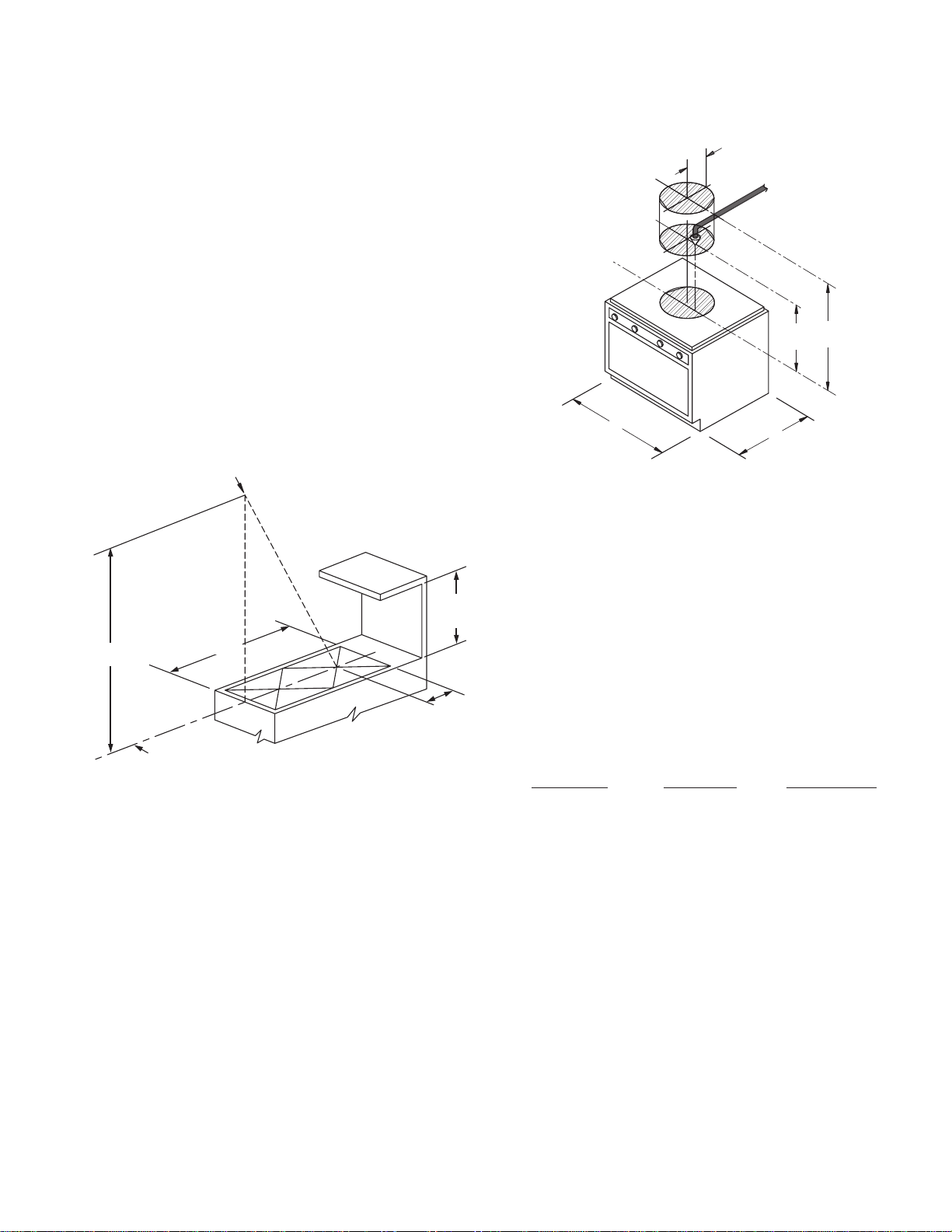
KITCHEN KNIGHT II Restaurant Fire Suppression Manual
SECTION 3 – SYSTEM DESIGN
UL EX3830 ULC EX3830
2014-NOV-10 REV. 06 PagE 3-7
NOZZLE COVERAGE AND PLACEMENT (Continued)
Appliance Protection (Continued)
2a. High-Proximity Backshelf Protection – When using the
2L nozzle for range protection with high-proximity backshelf, the maximum length of burners being protected must
not exceed 28 in. (711 mm) and the maximum area of the
burners must not exceed 336 in.2 (21677 mm2). The backshelf must be a minimum of 18 in. (458 mm) above the top
of the range and may overhang the burner by a maximum
of 11 in. (279 mm).
Note: although most shelves exceed 11 in. (279 mm) in
overall depth, make sure the shelf does not exceed 11 in.
(279 mm) overhang of the burner.
Nozzle must be located on the front edge of the front burner
and aimed at a point 10 in. (254 mm) forward from the
back edge of the back burner on the front-to-rear centerline. Nozzle must be mounted 24 in. to 35 in. (610 mm to
889 mm) above the hazard surface. See Figure 3-12.
SHELF CaN OVERHaNg BURNER(S)
a MaXIMUM OF 11 IN. (279 mm)
18 IN.
(457 mm)
MIN.
24-35 IN.
(610-889 mm)
MaX. 28 IN.
(711 mm)
R
2L
34 IN.
(864 mm)
L
W
006411
48 IN.
(1219 mm)
FIGuRE 3-13
Example: a four burner range has a hazard size of 20 in.
(508 mm) in length and 27 in. (685 mm) in width. Follow
down the Range Length in Table 3-4: Nozzle Positioning
until you come to 20 in. (508 mm). Continue down this
column until the correct width appears in the width column.
When the width of 27 in. (685 mm) is reached, read across
to the radius column to determine the size of radius allowed,
for positioning of the nozzle, from the hazard area centerline. In this example, the correct radius is 3 in. (76 mm). The
nozzle can be aimed straight down anywhere within a 3 in.
(76 mm) radius of the hazard area centerline.
10 IN. (254 mm)
FROM BaCK
FRONT TO REaR
CENTERLINE
HIgH PROXIMITY BaCK SHELF PROTECTION WITH THE 2L NOzzLE.
aREa OF PROTECTION PER NOzzLE: MaX. LENgTH OF BURNER
gRaTES 28 IN. (711 mm) aND MaX. aREa OF BURNER gRaTES
NOT TO EXCEED 336 IN. (21677 mm)
006845
BURNER
FIGuRE 3-12
2
3. Larger Burner Range (784 in.
(50580 mm2) maximum,
28 in. (711 mm) longest side maximum)
One nozzle is available for large range protection: High
proximity.
The Model 2L Nozzle (Part No. 551027) is used for high
proximity large range protection. This nozzle is a two flow
nozzle. when using high proximity protection, the range
cannot be under a backshelf. This nozzle must be located
34 in. to 48 in. (864 mm to 1219 mm) above the cooking
surface, and aimed directly down within the mounting
area, based on the hazard size, as described in the Nozzle
Positioning Chart. See Figure 3-13.
TABLE 3-4: NOZZLE POSITIONING
Range Range
Length - L width – w Radius – R
in. (mm) in. (mm) in. (mm)
18 (457) 18 (457) 7 1/8 (180)
18 (457) 19 (482) 6 3/4 (171)
18 (457) 20 (508) 6 3/8 (161)
18 (457) 21 (533) 6 (152)
18 (457) 22 (558) 5 5/8 (142)
18 (457) 23 (584) 5 1/4 (133)
18 (457) 24 (609) 4 3/4 (120)
18 (457) 25 (635) 4 3/8 (111)
18 (457) 26 (660) 4 (101)
18 (457) 27 (685) 3 5/8 (92)
18 (457) 28 (711) 3 1/8 (79)
Page 34

SECTION 3 – SYSTEM DESIGN
UL EX3830 ULC EX3830
PagE 3-8 REV. 06 2014-NOV-10
KITCHEN KNIGHT II Restaurant Fire Suppression Manual
NOZZLE COVERAGE AND PLACEMENT (Continued)
Appliance Protection (Continued)
TABLE 3-4: NOZZLE POSITIONING (Continued)
Range Range
Length - L width – w Radius – R
in. (mm) in. (mm) in. (mm)
19 (482) 18 (457) 6 3/4 (171)
19 (482) 19 (482) 6 3/8 (161)
19 (482) 20 (508) 6 (152)
19 (482) 21 (533) 5 5/8 (142)
19 (482) 22 (558) 5 1/4 (133)
19 (482) 23 (584) 4 7/8 (123)
19 (482) 24 (609) 4 1/2 (114)
19 (482) 25 (635) 4 1/8 (104)
19 (482) 26 (660) 3 3/4 (95)
19 (482) 27 (685) 3 1/4 (82)
19 (482) 28 (711) 2 7/8 (73)
20 (508) 18 (457) 6 3/8 (161)
20 (508) 19 (482) 6 (152)
20 (508) 20 (508) 5 5/8 (142)
20 (508) 21 (533) 5 1/4 (133)
20 (508) 22 (558) 4 7/8 (123)
20 (508) 23 (584) 4 1/2 (114)
20 (508) 24 (609) 4 1/8 (104)
20 (508) 25 (635) 3 3/4 (95)
20 (508) 26 (660) 3 3/8 (85)
20 (508) 27 (685) 3 (76)
20 (508) 28 (711) 2 5/8 (66)
21 (533) 18 (457) 6 (152)
21 (533) 19 (482) 5 5/8 (142)
21 (533) 20 (508) 5 1/4 (133)
21 (533) 21 (533) 5 (127)
21 (533) 22 (558) 4 5/8 (117)
21 (533) 23 (584) 4 1/4 (107)
21 (533) 24 (609) 3 7/8 (98)
21 (533) 25 (635) 3 1/2 (88)
21 (533) 26 (660) 3 1/8 (79)
21 (533) 27 (685) 2 3/8 (60)
21 (533) 28 (711) 2 1/4 (57)
22 (558) 18 (457) 5 5/8 (142)
22 (558) 19 (482) 5 1/4 (133)
22 (558) 20 (508) 4 7/8 (123)
22 (558) 21 (533) 4 5/8 (117)
22 (558) 22 (558) 4 1/4 (107)
22 (558) 23 (584) 3 7/8 (98)
22 (558) 24 (609) 3 1/2 (88)
22 (558) 25 (635) 3 1/8 (79)
22 (558) 26 (660) 2 3/4 (69)
22 (558) 27 (685) 2 3/8 (60)
22 (558) 28 (711) 2 (50)
23 (584) 18 (457) 5 1/4 (133)
23 (584) 19 (482) 4 7/8 (123)
23 (584) 20 (508) 4 1/2 (114)
23 (584) 21 (533) 4 1/4 (107)
23 (584) 22 (558) 3 7/8 (98)
Range Range
Length - L width – w Radius – R
in. (mm) in. (mm) in. (mm)
23 (584) 23 (584) 3 1/2 (88)
23 (584) 24 (609) 3 1/8 (79)
23 (584) 25 (635) 2 7/8 (73)
23 (584) 26 (660) 2 1/2 (63)
23 (584) 27 (685) 2 1/8 (53)
23 (584) 28 (711) 1 5/8 (41)
24 (609) 18 (457) 4 3/4 (120)
24 (609) 19 (482) 4 1/2 (114)
24 (609) 20 (508) 4 1/8 (104)
24 (609) 21 (533) 3 7/8 (98)
24 (609) 22 (558) 3 1/2 (88)
24 (609) 23 (584) 3 1/8 (79)
24 (609) 24 (609) 2 7/8 (73)
24 (609) 25 (635) 2 1/2 (63)
24 (609) 26 (660) 2 1/8 (53)
24 (609) 27 (685) 1 3/4 (44)
24 (609) 28 (711) 1 3/8 (34)
25 (635) 18 (457) 4 3/8 (111)
25 (635) 19 (482) 4 1/8 (104)
25 (635) 20 (508) 3 3/4 (95)
25 (635) 21 (533) 3 1/2 (88)
25 (635) 22 (558) 3 1/8 (79)
25 (635) 23 (584) 2 7/8 (73)
25 (635) 24 (609) 2 1/2 (63)
25 (635) 25 (635) 2 1/8 (53)
25 (635) 26 (660) 1 3/4 (44)
25 (635) 27 (685) 1 3/8 (34)
25 (635) 28 (711) 1 (25)
26 (660) 18 (457) 4 (101)
26 (660) 19 (482) 3 3/4 (95)
26 (660) 20 (508) 3 3/8 (85)
26 (660) 21 (533) 3 1/8 (79)
26 (660) 22 (558) 2 3/4 (69)
26 (660) 23 (584) 2 1/2 (63)
26 (660) 24 (609) 2 1/8 (53)
26 (660) 25 (635) 1 3/4 (44)
26 (660) 26 (660) 1 3/8 (34)
26 (660) 27 (685) 1 (25)
26 (660) 28 (711) 3/4 (19)
27 (685) 18 (457) 3 5/8 (92)
27 (685) 19 (482) 3 1/4 (82)
27 (685) 20 (508) 3 (76)
27 (685) 21 (533) 2 3/4 (69)
27 (685) 22 (558) 2 3/8 (60)
27 (685) 23 (584) 2 1/8 (53)
27 (685) 24 (609) 1 3/4 (44)
27 (685) 25 (635) 1 3/8 (34)
27 (685) 26 (660) 1 (25)
27 (685) 27 (685) 3/4 (19)
27 (685) 28 (711) 3/8 (9)
Page 35
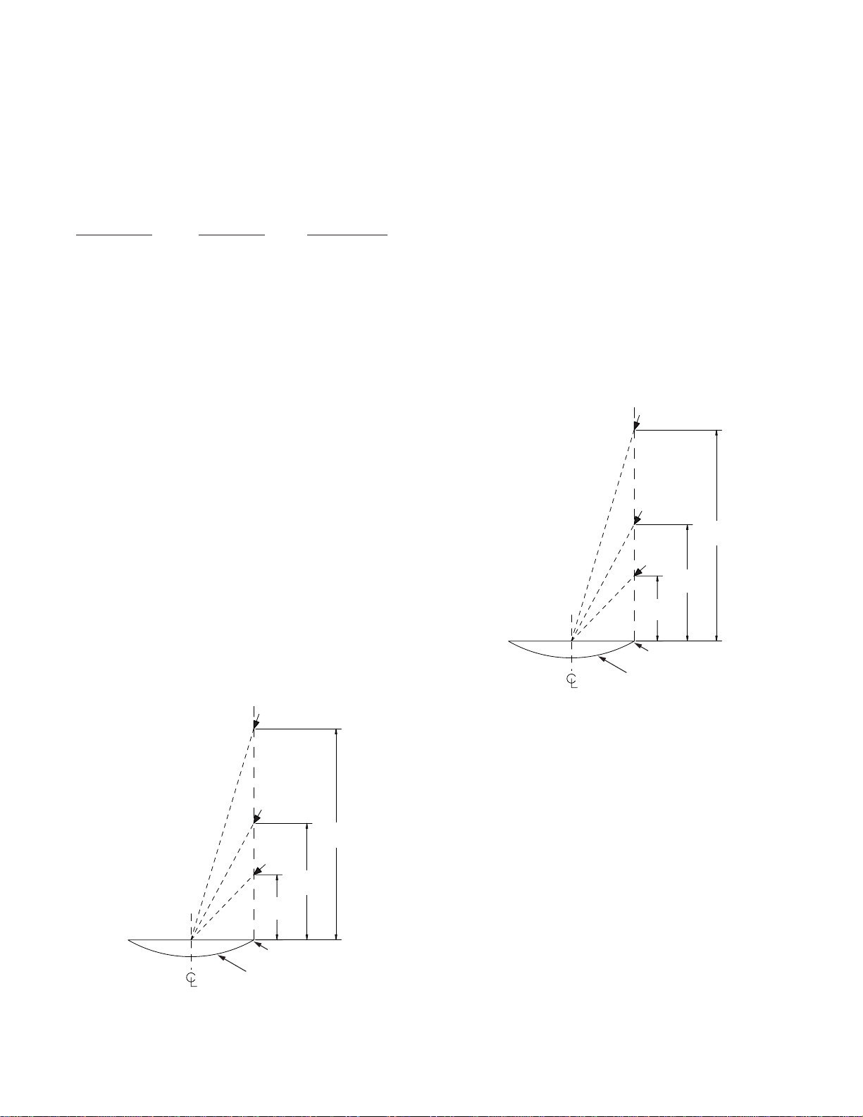
KITCHEN KNIGHT II Restaurant Fire Suppression Manual
SECTION 3 – SYSTEM DESIGN
UL EX3830 ULC EX3830
2014-NOV-10 REV. 06 PagE 3-9
NOZZLE COVERAGE AND PLACEMENT (Continued)
Appliance Protection (Continued)
TABLE 3-4: NOZZLE POSITIONING (Continued)
Range Range
Length - L width – w Radius – R
in. (mm) in. (mm) in. (mm)
28 (711) 18 (457) 3 1/8 (79)
28 (711) 19 (482) 2 7/8 (73)
28 (711) 20 (508) 2 5/8 (66)
28 (711) 21 (533) 2 1/4 (57)
28 (711) 22 (558) 2 (50)
28 (711) 23 (584) 1 5/8 (41)
28 (711) 24 (609) 1 3/8 (34)
28 (711) 25 (635) 1 (25)
28 (711) 26 (660) 3/4 (19)
28 (711) 27 (685) 3/8 (9)
28 (711) 28 (711) 0 (0)
4. Small wok (24 in. (609.6 mm) diameter x 6 in. (152 mm)
depth maximum)
Two nozzles are available for small wok protection: High
proximity and low proximity.
The 1H nozzle (Part No. 551029) is used for high proximity
wok protection. This nozzle is a one flow nozzle. The nozzle
must be located anywhere on the perimeter of the appliance, 24 in. to 48 in. (609.6 mm to 1219 mm) above the top
edge of the wok and aimed at the center of the wok. See
Figure 3-14.
The 1L nozzle (Part No. 551026) is used for low proximity
wok protection. This nozzle is a one flow nozzle. The nozzle
must be located anywhere on the perimeter of the appliance, 13 in. to 24 in. (331 mm to 609.6 mm) above the top
edge of the wok and aimed at the center of the wok. See
Figure 3-14.
1H
1H, 1L
48 IN.
(1219 mm)
1L
24 IN.
(609.6 mm)
13 IN.
(331 mm)
5. Large wok (greater than 24 in. to 30 in. (609.6 mm to
762 mm) diameter x 8 in. (203 mm) depth maximum)
Two nozzles are available for large wok protection: High
proximity and low proximity.
The 2H nozzle (Part No. 551028) is used for high proximity
wok protection. This nozzle is a two flow nozzle. The nozzle
must be located anywhere on the perimeter of the appliance, 24 in. to 48 in. (609.6 mm to 1219 mm) above the top
edge of the wok and aimed at the center of the wok. See
Figure 3-15.
The 2L nozzle (Part No. 551027) is used for low proximity
wok protection. This nozzle is a two flow nozzle. The nozzle
must be located anywhere on the perimeter of the appliance, 13 in. to 24 in. (331 mm to 609.6 mm) above the top
edge of the wok and aimed at the center of the wok. See
Figure 3-15.
2H
2H, 2L
48 IN.
(1219 mm)
2L
24 IN.
(609.6 mm)
13 IN.
(331 mm)
NOzzLE LOCaTED
006183PC
ON PERIMETER
30 IN. (762 mm)
DIaMETER MaXIMUM
FIGuRE 3-15
2
6. Small Griddle (1080 in.
(69677 mm2) x 36 in. (914 mm)
longest side maximum)
Two nozzles are available for small griddle protection: High
proximity and low proximity.
The 1H nozzle (Part No. 551029) is used for high proximity
griddle protection. This nozzle is a one flow nozzle. The
nozzle must be located above any corner of the hazard
surface, 24 in. to 48 in. (609.6 mm to 1219 mm) above the
cooking surface of the appliance and aimed at a point 12 in.
(304 mm) over and 12 in. (304 mm) in from the corner below
the nozzle. See Figure 3-16.
006183PC
NOzzLE LOCaTED
ON PERIMETER
24 IN. (609.6 mm)
DIaMETER MaXIMUM
FIGuRE 3-14
Page 36
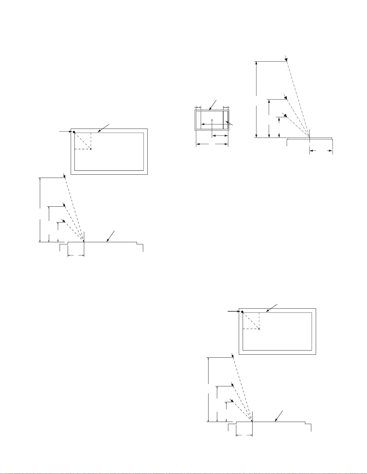
SECTION 3 – SYSTEM DESIGN
UL EX3830 ULC EX3830
PagE 3-10 REV. 06 2014-NOV-10
KITCHEN KNIGHT II Restaurant Fire Suppression Manual
NOZZLE COVERAGE AND PLACEMENT (Continued)
Appliance Protection (Continued)
The 1L nozzle (Part No. 551026) is used for low proximity
griddle protection. This nozzle is a one flow nozzle. The
nozzle must be located above any corner of the hazard
surface, 10 in. to 24 in. (254 mm to 609.6 mm) above the
cooking surface of the appliance and aimed at a point 12 in.
(304 mm) over and 12 in. (304 mm) in from the corner below
the nozzle. See Figure 3-16.
EDgE OF HazaRD aREa
NOzzLE (aNY
CORNER)
48 IN.
(1219 mm)
24 IN.
(609.6
mm)
1H
1H, 1L
1L
10 IN.
(254 mm)
12 IN.
(304 mm)
(304 mm)
12 IN.
(304 mm)
12 IN.
aIM POINT
HazaRD
SURFaCE
006184PC
FIGuRE 3-16
6a. Small Griddle (1080 in.2 (69677 mm2) x 36 in. (914 mm)
longest side maximum) Alternate Protection
Two nozzles are available for small griddle alternate
protection: High proximity and low proximity.
The 2H nozzle (Part No. 551028) is used for high proximity
griddle protection. This nozzle is a two flow nozzle. The
nozzle must be located 0 to 6 in. (0 to 152 mm) from short
side of the hazard surface, 24 in. to 48 in. (609.6 mm to
1219 mm) above the cooking surface of the appliance and
aimed at the center of the hazard area. See Figure 3-17.
The 2L nozzle (Part No. 551027) is used for low proximity
griddle protection. This nozzle is a two flow nozzle. The
nozzle must be located 0 to 6 in. (0 to 152 mm) from the
short side of the hazard surface, 13 in. to 24 in. (331 mm to
609.6 mm) above the cooking surface of the appliance and
aimed at the center of the hazard area. See Figure 3-17.
2H
6 IN.
(152
mm)
EDgE OF
HazaRD aREa
1/2 L
L
6 IN.
(152 mm)
NOzzLE
LOCaTION
zONE
48 IN.
(1219 mm)
2H, 2L
24 IN.
(609.6 mm)
2L
13 IN.
(331 mm)
1/2 L
FIGuRE 3-17
7. Large Griddle (1440 in.2 (92903 mm2) x 48 in. (1219 mm)
longest side maximum)
Two nozzles are available for large griddle protection: High
proximity and low proximity.
The 2H nozzle (Part No. 551028) is used for high proximity
griddle protection. This nozzle is a two flow nozzle. The
nozzle must be located above any corner of the hazard
surface, 24 in. to 48 in. (609.6 mm to 1219 mm) above the
cooking surface of the appliance and aimed at a point 12 in.
(304 mm) over and 12 in. (304 mm) in from the corner below
the nozzle. See Figure 3-18.
The 2L nozzle (Part No. 551027) is used for low proximity
griddle protection. This nozzle is a two flow nozzle. The
nozzle must be located above any corner of the hazard
surface, 10 in. to 24 in. (254 mm to 609.6 mm) above the
cooking surface of the appliance and aimed at a point 12 in.
(304 mm) over and 12 in. (304 mm) in from the corner below
the nozzle. See Figure 3-18.
EDgE OF
HazaRD aREa
NOzzLE (aNY
CORNER)
48 IN.
(1219 mm)
24 IN.
(609.6
mm)
2H
2H, 2L
2L
10 IN.
(254 mm)
12 IN.
(304 mm)
12 IN.
(304 mm)
aIM POINT
HazaRD
SURFaCE
12 IN.
(304 mm)
006184PC
FIGuRE 3-18
Page 37
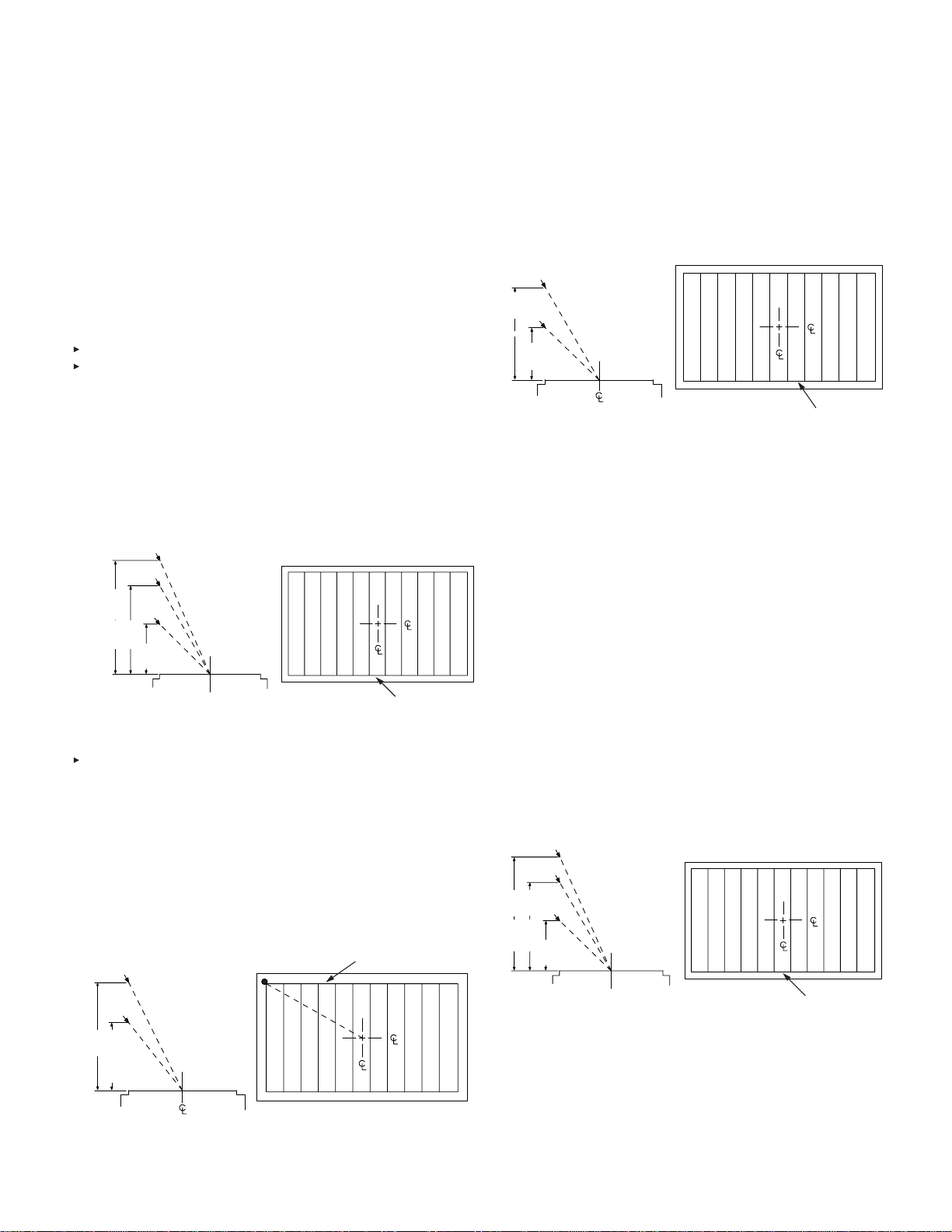
KITCHEN KNIGHT II Restaurant Fire Suppression Manual
SECTION 3 – SYSTEM DESIGN
UL EX3830 ULC EX3830
2014-NOV-10 REV. 06 PagE 3-11
NOZZLE COVERAGE AND PLACEMENT (Continued)
Appliance Protection (Continued)
8. Radiant/Electric Char-Broiler (624 in.2 (40257 mm2) x 26
in. (660 mm) longest side maximum)
Note: Radiant charbroilers are distinguished by the use of
heated metal strips (radiants) that are used for cooking.
Two nozzles are available for radiant char-broiler protection.
High proximity and low proximity.
The 1H nozzle (Part No. 551029) is used for high proximity
radiant char-broiler protection. This nozzle is a one flow
nozzle. The nozzle must be located anywhere within the
perimeter of the hazard area, 24 in. to 48 in. (609.6 mm to
1219 mm) above the cooking surface of the appliance and
aimed at the center of the broiler surface. See Figure 3-19.
The 1L nozzle (Part No. 551026) is used for low proximity
radiant char-broiler protection. This nozzle is a one flow
nozzle. The nozzle must be located anywhere on the
perimeter of the hazard surface, 13 in. to 24 in. (331 to
609.6 mm) above the cooking surface of the appliance and
aimed at the center of the broiler surface. See Figure 3-19.
1H NOzzLE LOCaTED ANYwHERE wITHIN THE PERIMETER
FOR HIgH PROXIMITY PROTECTION
1H
1L NOzzLE LOCaTED ANYwHERE ON THE PERIMETER
48 IN.
(1219 mm)
24 IN.
(609.6 mm)
1H, 1L
(331 mm)
1L
13 IN.
FOR LOW
PROXIMITY
PROTECTION
RADIANT
BROILER
EDgE OF
HazaRD aREa
006187PC
FIGuRE 3-19
2
9. Radiant/Electric Char-Broiler (864 in.
(55741 mm2) x
36 in. (914 mm) longest side maximum)
Two nozzles are available for radiant char-broiler protection:
High proximity and low proximity.
The 2H nozzle (Part No. 551028) is used for high proximity
radiant char-broiler protection. This nozzle is a two flow
nozzle. The nozzle must be located above any corner of
the hazard surface, 36 in. to 48 in. (915 mm to 1219 mm)
above the cooking surface of the appliance and aimed at the
center of the broiler surface. See Figure 3-20.
EDgE OF
2H
2H
48 IN.
(1219 mm)
36 IN.
(915 mm)
NOzzLE (aNY
CORNER)
HazaRD aREa
The 2L nozzle (Part No. 551027) is used for low proximity
radiant char-broiler protection. This nozzle is a two flow
nozzle. The nozzle must be located anywhere on the
perimeter of the hazard surface, 13 in. to 36 in. (331 mm
to 914 mm) above the cooking surface of the appliance and
aimed at the center of the broiler surface. See Figure 3-21.
NOzzLE LOCaTED aNYWHERE aLONg
2L
36 IN.
(914 mm)
2L
13 IN.
(331 mm)
PERIMETER
OF HazaRD
aREa
LOw PROXIMITY
RADIANT BROILER
006186PC
EDgE OF
HazaRD aREa
FIGuRE 3-21
2
10. Lava Rock Char-Broiler (624 in.
(40257 mm 2) x 26 in.
(660 mm) longest side maximum)
Note: Synthetic rock charbroilers are distinguished by the
use of lava, pumice, or synthetic rocks that are used for
cooking.
One nozzle is available for lava rock char-broiler protection:
High proximity and low proximity.
The 2L Nozzle (Part No. 551027) is used for high proximity
lava rock char-broiler protection. This nozzle is a two flow
nozzle. The nozzle must be located anywhere within the
perimeter of the hazard area, 24 in. to 35 in. (609.6 mm to
889 mm) above the cooking surface of the appliance and
aimed at the center of the broiler surface. See Figure 3-22.
The 2L nozzle (Part No. 551027) is used for low proximity
lava rock char-broiler protection. This nozzle is a two flow
nozzle. The nozzle must be located anywhere on the
perimeter of the hazard surface, 15 in. to 24 in. (381 mm to
609.6 mm) above the cooking surface of the appliance and
aimed at the center of the broiler surface. See Figure 3-22.
2L NOzzLE LOCaTED ANYwHERE wITHIN THE PERIMETER
FOR HIgH PROXIMITY PROTECTION
2L NOzzLE LOCaTED ANYwHERE ON THE PERIMETER
FOR LOW
PROXIMITY
PROTECTION
LAVA ROCk
CHAR-BROILER
EDgE OF
HazaRD aREa
006187PC
35 IN.
(889 mm)
24 IN.
(609.6
mm)
2L
2L
2L
15 IN.
(381 mm)
FIGuRE 3-22
HIGH PROXIMITY
RADIANT BROILER
006185PC
FIGuRE 3-20
Page 38
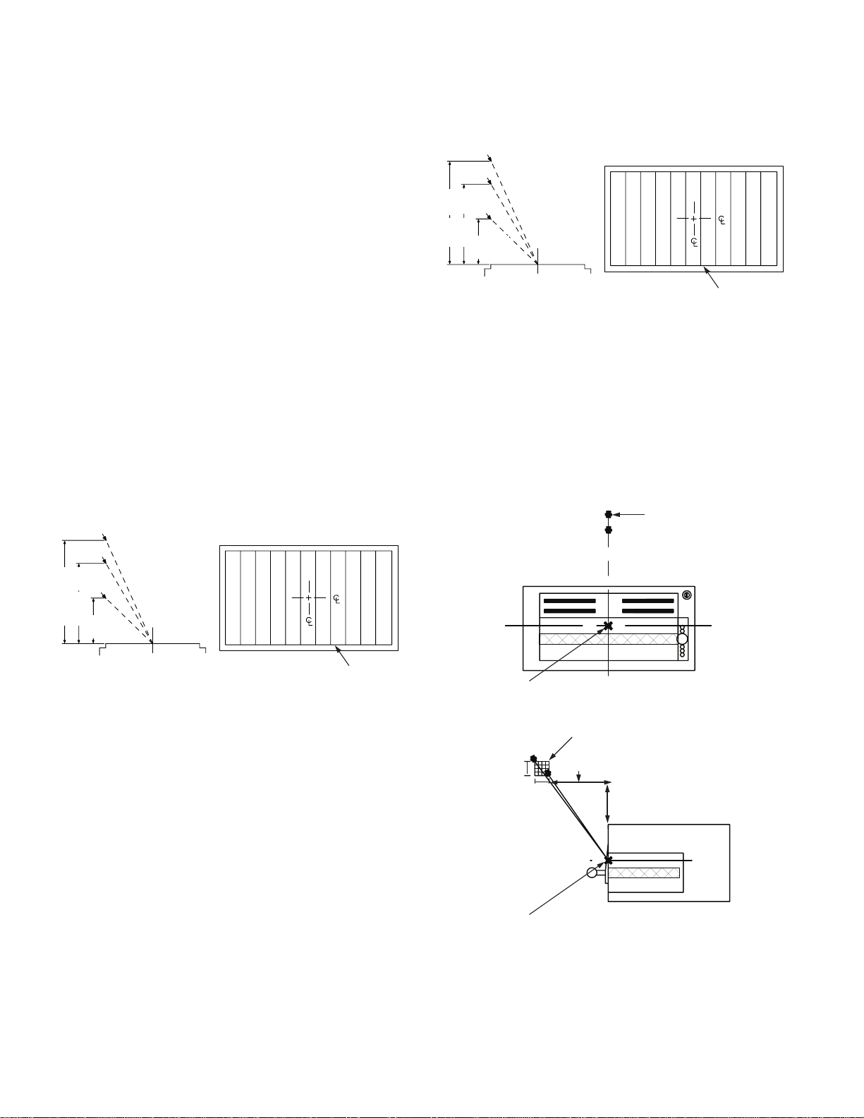
SECTION 3 – SYSTEM DESIGN
UL EX3830 ULC EX3830
PagE 3-12 REV. 06 2014-NOV-10
KITCHEN KNIGHT II Restaurant Fire Suppression Manual
NOZZLE COVERAGE AND PLACEMENT (Continued)
Appliance Protection (Continued)
2
11. Natural Class “A” Charcoal Char-Broiler (480 in.
2
mm
) x 24 in. (609.6 mm) longest side maximum)
(30967
Note: Class “a” (natural) charbroilers are distinguished by
the use of charcoal, mesquite chips, chunks, and/or logs
that are used for cooking.
Two nozzles are available for natural charcoal char-broiler
protection. High proximity and low proximity. The maximum
depth of fuel (charcoal) must not exceed 6 in. (152 mm).
The 1H nozzle (Part No. 551029) is used for high proximity
natural charcoal char-broiler protection. This nozzle is a one
flow nozzle. The nozzle must be located anywhere within
the perimeter of the hazard area, 24 in. to 35 in. (609.6 mm
to 889 mm) above the cooking surface of the appliance and
aimed at the center of the broiler surface. See Figure 3-23.
The 1L nozzle (Part No. 551026) is used for low proximity
natural charcoal char-broiler protection. This nozzle is a one
flow nozzle. The nozzle must be located anywhere on the
perimeter of the hazard surface, 15 in. to 24 in. (381 mm to
609.6 mm) above the cooking surface of the appliance and
aimed at the center of the broiler surface. See Figure 3-23.
1H NOzzLE LOCaTED ANYwHERE wITHIN THE
PERIMETER FOR HIgH PROXIMITY PROTECTION
1L NOzzLE LOCaTED ANYwHERE ON THE PERIMETER
FOR LOW
PROXIMITY
PROTECTION
1L, 1H
35 IN.
(889 mm)
24 IN.
(609.6
mm)
1H
1L
15 IN.
(381 mm)
1H NOzzLE LOCaTED ANYwHERE wITHIN THE PERIMETER
FOR HIgH PROXIMITY PROTECTION
1L NOzzLE LOCaTED ANYwHERE ON THE PERIMETER
FOR LOW
PROXIMITY
PROTECTION
MESquITE
CHAR-BROILER
EDgE OF
HazaRD aREa
006187PC
1L, 1H
35 IN.
(889 mm)
24 IN.
(609.6
(mm)
1H
1L
15 IN.
(381 mm)
FUEL DEPTH MUST NOT
EXCEED 6 IN. (152 mm)
FIGuRE 3-24
13. Salamander Broiler (internal broiler dimensions of 31 in.
(787 mm) x 15.5 in. (393 mm) and a maximum grate
opening of 31 in. (787 mm) x 7.75 in. (196 mm)
The 1H nozzle (Part No. 551029) is used for broiler protec-
tion. This is a one-flow nozzle. The nozzle must be centered
12 to 14 in. (305 mm to 355 mm) in front of the salamander
and positioned 16 to 18 in. (407 mm to 457 mm) above the
top of the salamander. The nozzle must be aimed to the
center of the opening above the salamander cooking grate.
See Figure 3-25.
1H NOzzLE
(PaRT NO. 551029)
FUEL DEPTH MUST NOT
EXCEED 6 IN. (152 mm)
NATuRAL CHARCOAL
CHAR-BROILER
006187PC
EDgE OF
HazaRD aREa
FIGuRE 3-23
12. Mesquite Char-Broiler (480 in.2 x (30967 mm2) 24 in.
(609.6 mm) longest side maximum)
Two nozzles are available for mesquite char-broiler protec-
tion. High proximity and low proximity. The maximum depth
of fuel (wood) must not exceed 6 in. (152 mm).
The 1H nozzle (Part No. 551029) is used for high proximity
mesquite char-broiler protection. This nozzle is a one flow
nozzle. The nozzle must be located anywhere within the
perimeter of the hazard area, 24 in. to 35 in. (609.6 to 889
mm) above the cooking surface of the appliance and aimed
at the center of the broiler surface. See Figure 3-24.
The 1L nozzle (Part No. 551026) is used for low proximity
mesquite charcoal char-broiler protection. This nozzle is a
one flow nozzle. The nozzle must be located anywhere on
the perimeter of the hazard surface, 15 in. to 24 in. (381
mm to 609.6 mm) above the cooking surface of the appliance and aimed at the center of the broiler surface. See
Figure 3-24.
aIM aT CENTER OF THE TOP BROILER
OPENINg WHEN THE gRaTE IS
LOCaTED IN THE MIDDLE POSITION
NOzzLE
LOCaTION zONE
2 IN.
(50 mm)
2 IN.
(50 mm)
aIM aT CENTER OF THE TOP BROILER
OPENINg WHEN THE gRaTE IS
LOCaTED IN THE MIDDLE POSITION
12 IN.
(305 mm)
16 IN.
(407 mm)
008435
008436
FIGuRE 3-25
Page 39
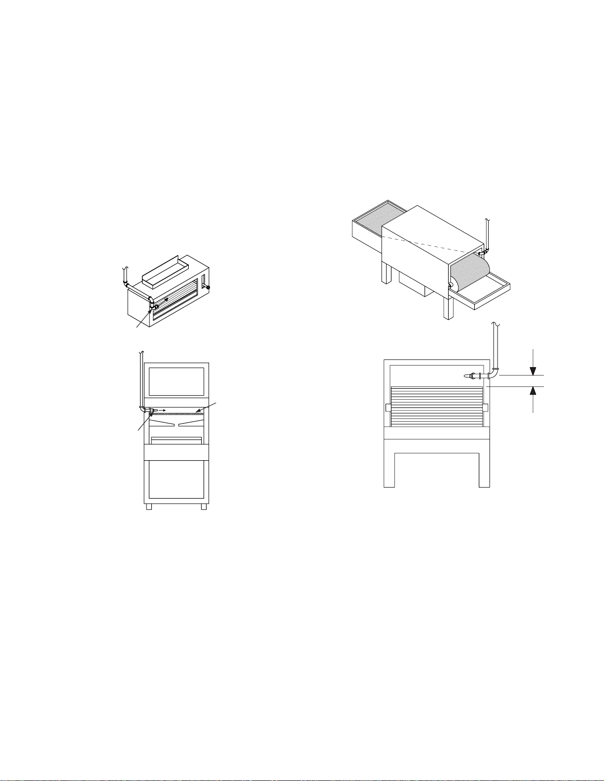
KITCHEN KNIGHT II Restaurant Fire Suppression Manual
SECTION 3 – SYSTEM DESIGN
UL EX3830 ULC EX3830
2014-NOV-10 REV. 06 PagE 3-13
NOZZLE COVERAGE AND PLACEMENT (Continued)
Appliance Protection (Continued)
13a. upright/Salamander Broiler (internal chamber 1064 in.
2
x 36 in. (68645 mm2 x 914 mm) longest side maximum)
One nozzle is available for upright/salamander broiler
protection.
The 1L nozzle (Part No. 551026) is used for broiler protec-
tion. This nozzle is a one flow nozzle. The nozzle must be
located above the grate, at the front edge of the appliance,
outside the broiling chamber, and pointed at the back
opposite corner of the broiler chamber. The nozzle must
be aimed parallel to the broiler grate surface. See Figure
3-26.
1L NOzzLE aIMED
aT BaCK OPPOSITE
CORNER
SALAMANDER BROILER
14. Chain Broiler (internal chamber 1026 in.
2
(66193 mm2) x
38 in. (965 mm) longest side maximum)
One nozzle is available for chain broiler protection.
The 1L nozzle (Part No. 551026) is used for broiler protec-
tion. This nozzle is a one flow nozzle. The nozzle must be
located 1 in. to 3 in. (26 mm to 76 mm) above the surface
of the chain, at the front edge of the appliance, and pointed
at the opposite diagonal corner. The nozzle must be aimed
parallel to the chain surface. See Figure 3-27.
1L NOzzLE aIMED
aT OPPOSITE
DIagONaL CORNER
1L NOzzLE aIMED
aT BaCK OPPOSITE
CORNER
BROILER
CHaMBER
uPRIGHT
BROILER
006189PC
FIGuRE 3-26
006190PC
1-3 IN.
(26-76 mm)
FIGuRE 3-27
Page 40
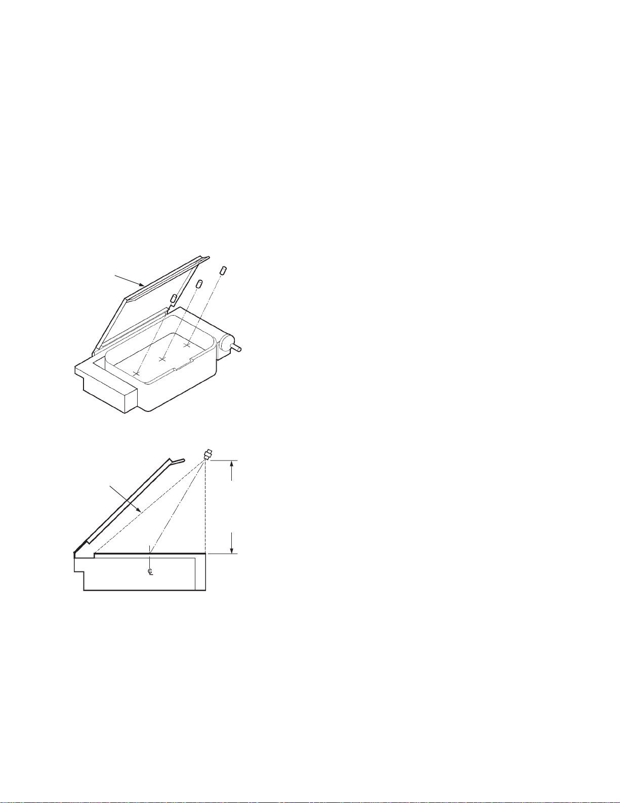
SECTION 3 – SYSTEM DESIGN
UL EX3830 ULC EX3830
PagE 3-14 REV. 06 2014-NOV-10
NOZZLE COVERAGE AND PLACEMENT (Continued)
Appliance Protection (Continued)
15. Tilt Skillet/Braising Pan
Protection for tilt skillet or braising pans is to be based
upon the coverage limitations provided for deep fat fryer
protection. Coverage limitations are based on fryer sizes
including drip boards. Exception: Tilt skillets and braising
2
pans may exceed the maximum of 6 ft
(0.5 m2) total when
modularizing. Tilt skillets and braising pans generally utilize
a hinged cover. Fryer protection nozzles are to be placed
toward the front of the appliance to minimize the potential
for the tilt skillet or braising pan cover to interfere with the
nozzle discharge. See Figure 3-28.
COVER MUST
NOT INTERFERE
WITH NOzzLE
DISCHaRgE
2 FT
(0.6 m)
KITCHEN KNIGHT II Restaurant Fire Suppression Manual
000011
4 FT
(1.2 m)
THE NOzzLE IS TO BE PLaCED TOWaRD THE FRONT OF THE aPPLIaNCE
TO MINIMIzE THE POTENTIaL FOR THE SKILLET OR BRaISINg PaN COVER
TO INTERFERE WITH THE NOzzLE DISCHaRgE.
COVER MUST
NOT INTERFERE
WITH EDgE OF
DISCHaRgE
PaTTERN
FRYER NOzzLE USED FOR TILT SKILLET OR BRaISINg PaN PROTECTION
MUST BE POSITIONED NEaR THE FRONT EDgE OF THE PaN aND aIMED
aT THE FRONT TO BaCK CENTERLINE OF THE PaN. THE DISCHaRgE
FROM THE NOzzLE(S) MUST COMPLETELY CLEaR THE PaN COVER WITH
aN UNOBSTRUCTED VIEW TO THE BaCK OF THE PaN.
FOR MINIMUM
aND MaXIMUM
NOzzLE
HEIgHTS,
REFER TO
FRYER NOzzLE
PaRaMETERS
000071
FIGuRE 3-28
Page 41
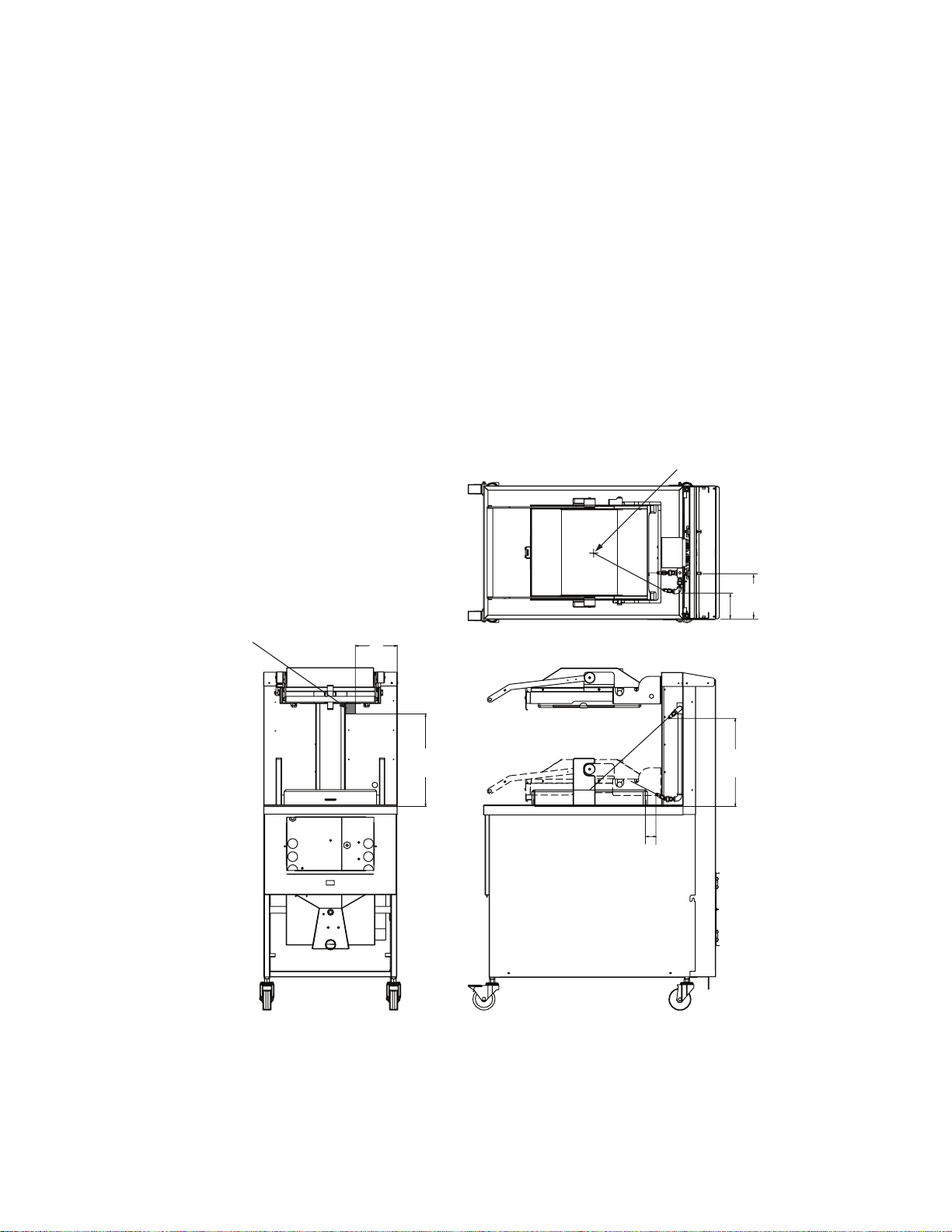
KITCHEN KNIGHT II Restaurant Fire Suppression Manual
SPECIFIC APPLICATION BY MODEL
Henny Penny Fryer – Mono Rail Center Lift System –
Models 690, 691, 692
• Nozzle Type: One – 2H (upper position) and One – 2F (lower
position)
• Nozzle Location:
2H Nozzle (upper position): From the Tee Block; nozzle tip
located 16 in. (406 mm) up from base of fryer surface and 5
in. (127 mm) in from right side of appliance back shroud –
aimed to discharge at center point of fry vat. See Figure 3-29.
2F Nozzle (lower position): Running down from the Tee
Block to the base of the fryer, nozzle tip is located 2 in.
(50 mm) from back side of fry vat, and 8 in. (203 mm) in from
the right side of appliance back shroud. See Figure 3-29.
The 2F nozzle is a flat spray nozzle and the spray must be
horizontal to that of the edge of the back lip of the fry vat.
SECTION 3 – SYSTEM DESIGN
UL EX3830 ULC EX3830
2014-NOV-10 REV. 06 PagE 3-15
• System Coverage:
Each fryer requires a minimum of one PCL 300 agent Tank
discharging through the two two-flow nozzles (2H and 2F).
• Piping Limitations – Follow the limitations for the PCL 300
agent Tank.
aIMINg POINT
NOTE: VaT DIMENSIONS –
16 IN. (406 mm) WIDTH
20 1/4 IN. (514 mm) LENgTH
28 1/2 IN. (723 mm) DEPTH
MaXIMUM LID HEIgHT aBOVE VaT
15 IN. (381 mm)
TEE
BLOCK
7 9/16 IN.
(192 mm)
16 13/16 IN.
(427 mm)
TOP VIEw
2 IN.
(508 mm)
5 IN.
(127 mm)
16 IN.
(406 mm)
8 IN.
(203 mm)
FRONT VIEw
(TEE BLOCk LOCATION)
007516
SIDE VIEw
FIGuRE 3-29
Page 42
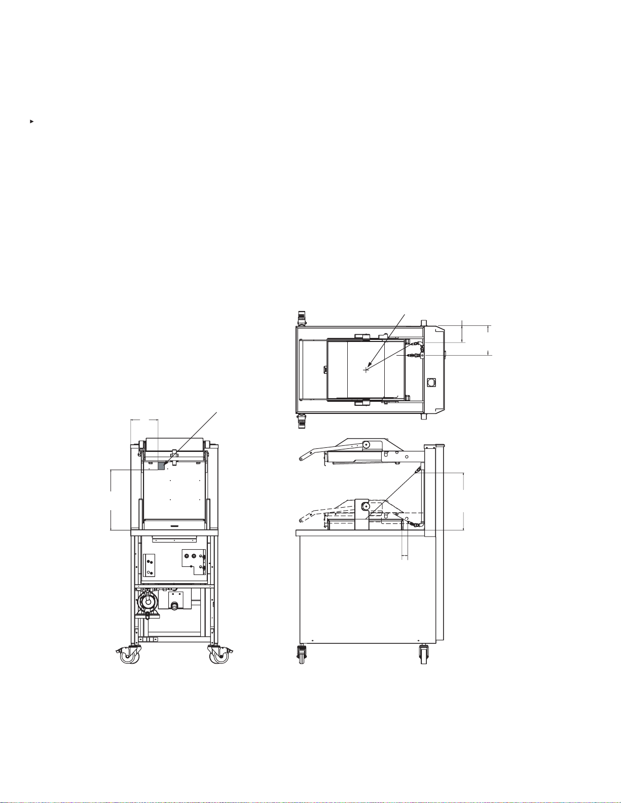
SECTION 3 – SYSTEM DESIGN
UL EX3830 ULC EX3830
PagE 3-16 REV. 06 2014-NOV-10
SPECIFIC APPLICATION BY MODEL (Continued)
Henny Penny Fryer – Dual Lift System – Models 580, 581,
582, 590, 591, 592, 680, 682, 691
• Nozzle Type: One – 2H (upper position) and One – 2F (lower
position)
• Nozzle Location:
2H Nozzle (upper position): From the Tee Block; nozzle tip
located 16 in. (406 mm) up from base of fryer surface and 5
in. (127 mm) in from left side of appliance back shroud –
aimed to discharge at center point of fry vat. See Figure 3-30.
2F Nozzle (lower position): Running down from the Tee
Block to the base of the fryer, nozzle tip is located 2 in.
(50 mm) from back side of fry vat, and 8 in. (203 mm) in from
the left side of appliance back shroud. See Figure 3-30.
The 2F nozzle is a flat spray nozzle and the spray must be
horizontal to that of the edge of the back lip of the fry vat.
KITCHEN KNIGHT II Restaurant Fire Suppression Manual
• System Coverage:
Each fryer requires a minimum of one PCL 300 agent Tank
discharging through the two two-flow nozzles (2H and 2F).
• Piping Limitations – Follow the limitations for the PCL 300
agent Tank.
NOTE: VaT DIMENSIONS –
16 IN. (406 mm) WIDE
20 1/4 IN. (514 mm) LENgTH
28 1/2 IN. (723 mm) DEPTH
MaXIMUM LID HEIgHT aBOVE VaT
15 IN. (381 mm)
7 9/16 IN.
(192 mm)
16 13/16 IN.
(427 mm)
TEE
BLOCK
TOP VIEw
aIMINg POINT
2 IN.
(50 mm)
5 IN.
(127 mm)
16 IN.
(406 mm)
8 IN.
(203 mm)
FRONT VIEw
(TEE BLOCk LOCATION)
007515
SIDE VIEw
FIGuRE 3-30
Page 43
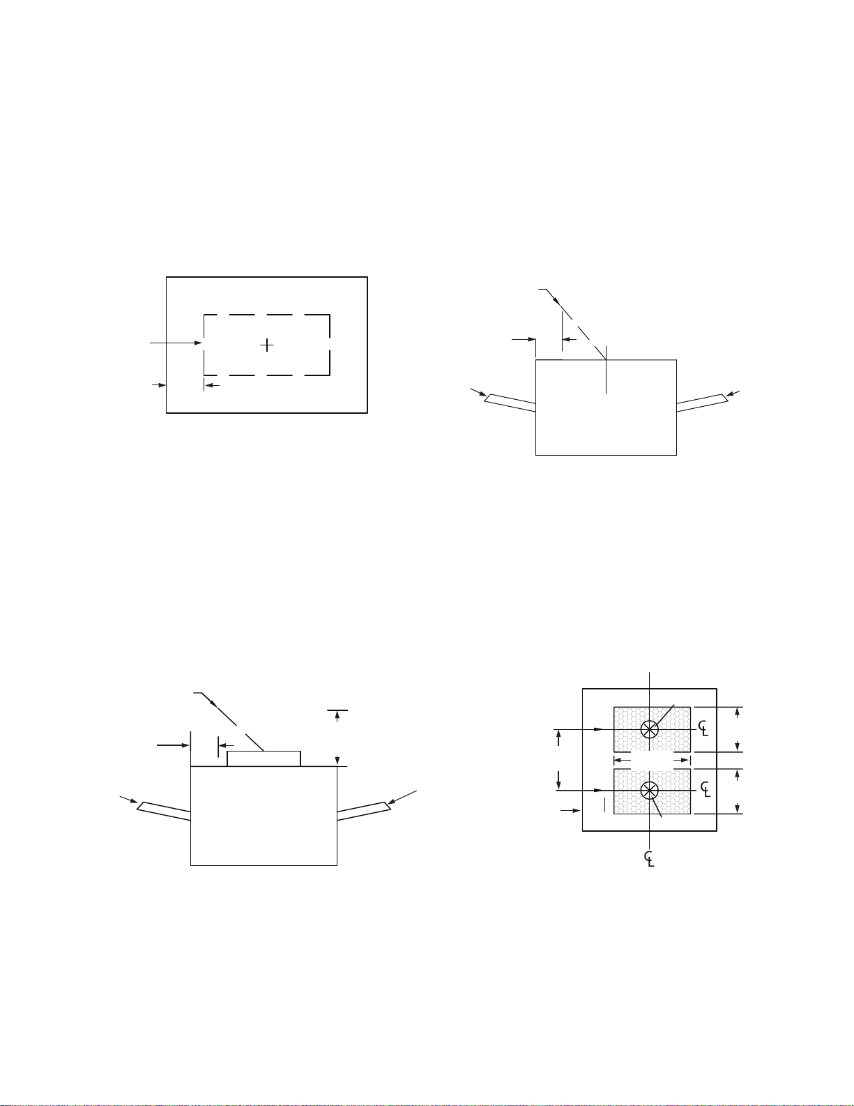
KITCHEN KNIGHT II Restaurant Fire Suppression Manual
SPECIFIC APPLICATION BY MODEL (Continued)
Nieco Broiler – Model MPB 84 with Catalyst ONLY
Nozzle Type: 2L
Nozzle quantity: One
Nozzle Height: 20 in. (508 mm)
Nozzle Location: 6.5 in (165 mm) from any edge of the appliance top
Nozzle Direction: aim at center of opening (see Figure 3-31)
BACk
6 1/2 IN. (165 mm)
FROM OUTSIDE
EDgE OF THE
aPPLIaNCE
TOP VIEw
008095
FRONT
6 1/2 IN. (165 mm) FROM
OUTSIDE EDgE
OF THE aPPLIaNCE
PRODUCT
OUTPUT
2L NOzzLE
SECTION 3 – SYSTEM DESIGN
UL EX3830 ULC EX3830
2014-NOV-10 REV. 06 PagE 3-17
PRODUCT
INPUT
Note that in applications that cannot utilize an overhead application,
standard chain broiler protection is acceptable using the
1L nozzle installed at the opening.
Nieco Broiler – Model JF94E Electric Broiler with Catalyst
High Proximity Protection (see Figure 3-32)
Nozzle Type: 2H
Nozzle quantity: Two
Nozzle Height: 20 in. (508 mm)
Nozzle Location: 6.5 in. (165 mm) from front or back edge of hazard
Nozzles positioned 15 in. (381 mm) apart
Nozzle Aim Point: Center of catalyst
(2) – 2H NOzzLE
20 IN.
6 1/2 IN. (165 mm)
FROM EDgE
PRODUCT
OUTPUT
(508 mm)
NOzzLE HEIgHT
FRONTBACk
PRODUCT
INPUT
BACk
(2) – 2H NOzzLE
BACk
15 IN.
(381 mm)
6 1/2 IN. (165 mm)
FROM EDgE
SIDE VIEw
008096
aIM CENTER
15 IN.
(381 mm)
aIM CENTER
FRONT
008429
FIGuRE 3-31
FRONT
8 IN.
(203 mm)
8 IN.
(203 mm)
SIDE VIEw
008434
TOP VIEw
FIGuRE 3-32
Page 44
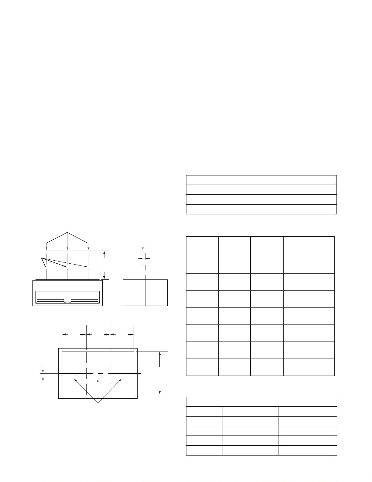
SECTION 3 – SYSTEM DESIGN
UL EX3830 ULC EX3830
PagE 3-18 REV. 06 2014-NOV-10
KITCHEN KNIGHT II Restaurant Fire Suppression Manual
SPECIFIC APPLICATION BY MODEL (Continued)
Baker’s Pride Broiler – Models CH6, CH8, CH10, XX6, XX8,
XX10 (with wood Smoker Box and Chip Holders)
Nozzle Type: 2H
Nozzle quantity: Three
Nozzle Height: 33 in. (839 mm) to 35 in. (889 mm)
above the hazard surface
Nozzle Location: Each nozzle is to protect 1/3 of the
cooking area and located in the horizontal center of the respective cooking area;
1 in. (25 mm) forward of the longitudinal
center line of the cooking area
See Figure 3-33
Nozzle Aiming Point: Horizontal center of the respective
cooking area, 1 in. (25 mm) forward
of the longitudinal center line of the
cooking area
See Figure 3-33
Note: Smoker Box and Chip Holders cannot exceed logs 4 in.
(101 mm) in diameter and a maximum allowable wood depth of
4 in. (101 mm).
2H NOzzLES
1 IN. (25 mm)
FORWaRD
OF
CENTERLINE
OF COOKINg
aREa
CENTER
LINE OF
RESPECTIVE
COOKINg
aREa
2H NOzzLES
NOzzLE HEIgHT
33 IN. - 35 IN.
(839 mm - 889 mm)
PIPING LIMITATIONS
Once the nozzle placement and quantity of tanks has been
determined, it is necessary to determine the piping configurations between the tank and the nozzles. This section contains
the guidelines and limitations for designing the distribution piping
so that the wet chemical agent will discharge from the nozzles
at a proper flow rate. These limitations must also be referred to
when selecting the mounting location for the tanks.
The maximum pipe lengths are based on internal pipe volume.
Each size tank is allowed a minimum and maximum total volume
of piping, calculated in milliliters.
There is no need to distinguish between what portion of the
piping is supply line and what portion is branch line. Only the
total volume of the complete piping network has to be considered.
TABLE 3-5: VOLuME
1/4 in. pipe = 20.5 mls/ft
3/8 in. pipe = 37.5 mls/ft
1/2 in. pipe = 59.8 mls/ft
3/4 in. pipe = 105.0 mls/ft
Note: agent Distribution hose equals 300 mls per hose.
TABLE 3-6: TANkS
Maximum Volume
allowed Between
First Nozzle and
Last Nozzle
(milliliters)
Tank
Size
1.6 gallon
Maximum
Maximum
Flow
Numbers
Pipe
Volume
(milliliters)
5 1500 600
PCL-160
1 IN. (25 mm)
FORWaRD OF
CENTERLINE OF
COOKINg aREa
1/3 OF
COOKINg
aREa
RESPECTIVE COOKINg aREa
1/3 OF
COOKINg
aREa
HORIzONTaL CENTER OF
1/3 OF
COOKINg
aREa
008496
COOKINg
aREa
008497
FIGuRE 3-33
3.0 gallon
10 1910 1125
PCL-300
4.6 gallon
14 3400 3000
PCL-460
4.6 gallon
15 2600 2000
PCL-460
6.0 gallon
PCL-600
6.0 gallon
PCL-600
19 4215 1688
per side
20 3465 1313
per side
* all piping, including nozzle drops, must be included in the
piping calculations.
Minimum Pipe Volumes for a Fryer, Range, and Wok
Cylinder Size Entire System at or before appliance
PCL 160 239 ml - 1 Flow Pt 180 ml - 1 Flow Pt
PCL 300 300 ml - 4 Flow Pts 239 ml - 2 Flow Pts
PCL 460 660 ml - 10 Flow Pts 180 ml - 2 Flow Pts
PCL 600 960 ml - 14 Flow Pts 120 ml - 2 Flow Pts
Page 45
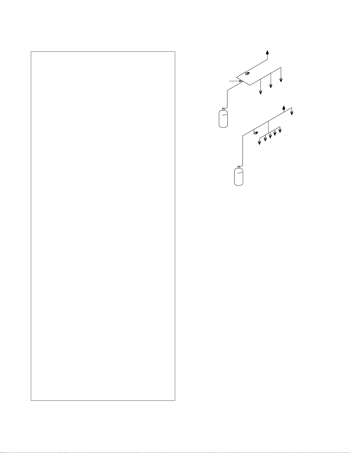
KITCHEN KNIGHT II Restaurant Fire Suppression Manual
General Piping Requirements
1. Split piping and straight piping are both allowed on a
PCL-160, PCL-300 and PCL-460 system.
2. PCL-600 systems must use split piping only, with no
nozzle located before the split, and with a maximum of
14 flow points per side. 1/2 in. minimum piping must be
used up to the first split.
3. Maximum volume for 1/4 in. pipe between a nozzle and
the preceding tee is 410 mls.
4. Maximum flow numbers for 1/4 in. pipe is six.
5. Maximum number of elbows between a nozzle and the
preceding tee is five.
6. Maximum of 25 elbows are allowed in the total piping
system.
7. Maximum difference in elevation between the tank
outlet and any nozzle, or the tank outlet and the highest
or lowest horizontal pipe run, is 10 ft (3.0 m).
8. No traps are allowed in the piping network.
9. Pipe lengths are measured from center to center of
fittings.
10. The internal equivalent length volume of fittings does
not have to be considered as part of the total pipe
volume.
11. When utilizing different size pipe in the system, the
largest size must start first and the additional pipe must
decrease as it approaches the nozzle.
12. Elbow(s) or swivel adaptors located at the nozzles
do not have to be counted in the 25 elbow maximum
requirement.
13. Reducing bushings are allowed when reducing to a
smaller pipe size.
14. additional piping requirements when protecting a
range, wok, or a fryer:
• PCL-160 – Minimum of 239 ml and one flow number
required in total system. Of that minimum, 180 ml
must be utilized at or before the range, wok, or fryer.
• PCL-300 - Minimum of 300 ml and four flow numbers
required in total system. Of that minimum, 239 ml and
two flow numbers must be utilized at or before the
range, wok, or fryer.
• PCL-460 – Minimum of 660 ml and ten flow numbers
required in total system. Of that minimum, 180 ml and
two flow numbers must be utilized at or before the
range, wok, or fryer.
• PCL-600 – Minimum of 960 ml and fourteen flow
numbers required in total system. Of that minimum,
120 ml and two flow numbers must be utilized at or
before the range, wok, or fryer.
SECTION 3 – SYSTEM DESIGN
UL EX3830 ULC EX3830
2014-NOV-10 REV. 06 PagE 3-19
SUPPLY PIPE
MUST ENTER BULL
SIDE OF TEE
SPLIT PIPING (REquIRED
ON PCL600 SYSTEMS)
STRAIGHT PIPING
006191PC
FIGuRE 3-34
Design Steps
Step No. 1 Determine number of flow points required based
on duct size, plenum size and type, and size of all
appliances.
Step No. 2 Determine size and quantity of tanks required. Refer
to Rule No. 14 in general Piping Requirements to
determine the maximum amount of flow numbers
allowed per each tank size.
Step No. 3 Layout nozzles, piping diagram, and tank location.
Determine pipe lengths as accurate as possible.
Make certain maximum number of elbows is not
exceeded. Note: Tanks cannot be manifolded
together. Each tank must have a separate
piping network.
Step No. 4 add all the lengths of each pipe run and multiply
by the mls/ft listed in the Table 3-5: Volume. If the
sum falls within the acceptable range noted in the
general Piping Requirements, that pipe size is
acceptable. If the calculated volume is too large,
recalculate the volume using the ml per foot of
a smaller pipe size. Pipe sizes can be mixed but
Rule No. 11 of the general Piping Requirements
must be followed.
Step No. 5 Check to make certain minimum volumes,
maximum volumes and maximum volume allowed
between first nozzle and last nozzle is not
exceeded (Table 3-6: Tanks). Check each rule
in general Piping Requirements to make certain
none have been exceeded. If any requirement
is exceeded, change to a different pipe size and
recalculate.
Page 46
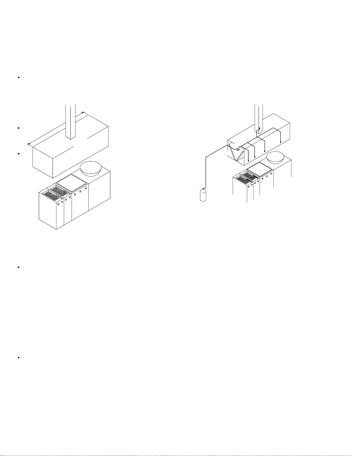
SECTION 3 – SYSTEM DESIGN
UL EX3830 ULC EX3830
PagE 3-20 REV. 06 2014-NOV-10
KITCHEN KNIGHT II Restaurant Fire Suppression Manual
Design Steps (Continued)
Example
The cooking area that requires protection consists of a single
56 in. (1422 mm) perimeter exhaust duct, a 10 ft (3.0 m) long
“V” bank plenum, two 18 in. (457 mm) wide x 24 in. (609 mm)
fryers, a 30 in. (762 mm) x 36 in. (914 mm) wide griddle, and a
24 in. (609 mm) diameter wok. See Figure 3-35.
10 FT
(3.0 m)
14 IN.
(355 mm)
14 IN.
(355 mm)
TWO 18 IN. (457 mm) X 24 IN.
(609 mm) FRYERS
ONE 30 IN. (762 mm) X 36 IN.
(914 mm) gRIDDLE
ONE 24 IN. (609 mm)
DIaMETER WOK
006192PC
Step No. 3 Make an accurate sketch of the cooking lineup
and the hood. Sketch in the tank location and
all the piping required for the total system. Make
certain all pipe lengths and number of elbows are
as accurate as possible. Check the general Piping
Requirements on Page 3-19 to determine that the
minimum and maximum requirements are met.
See Figure 3-36.
6
IN.
3 FT
2 FT
2 FT
006193PC
2 FT
2 FT
5 FT
6 IN.
14 FT
2 FT
1.5 FT
6 IN.
1 FT
6 IN.
2 FT
2
FT
2
FT
2 FT
2
FT
FIGuRE 3-36
FIGuRE 3-35
Step No. 1 Determine number of flow points required.
• 56 in. (1422 mm) perimeter duct requires one,
two flow nozzle
• 10 ft (3.0 m) “V” bank hood requires one, one
flow nozzle
• 18 in. x 24 in. (457 mm x 609 mm) fryer requires
one, two flow nozzle
• 18 in. x 24 in. (457 mm x 609 mm) fryer requires
one, two flow nozzle
• 30 in. x 36 in. (762 mm x 914 mm) griddle
requires one, one flow nozzle
• 24 in. (609 mm) diameter wok requires one, one
flow nozzle
TOTAL FLOw NuMBERS – NINE
Step No. 2 Determine size and quantity of tanks required.
Referring to Rule No. 14 in general Piping
Requirements (Page 3-19), a PCL-300 and
a PCL-460 can supply ten flows, therefore, a
PCL-300 can be utilized.
Page 47
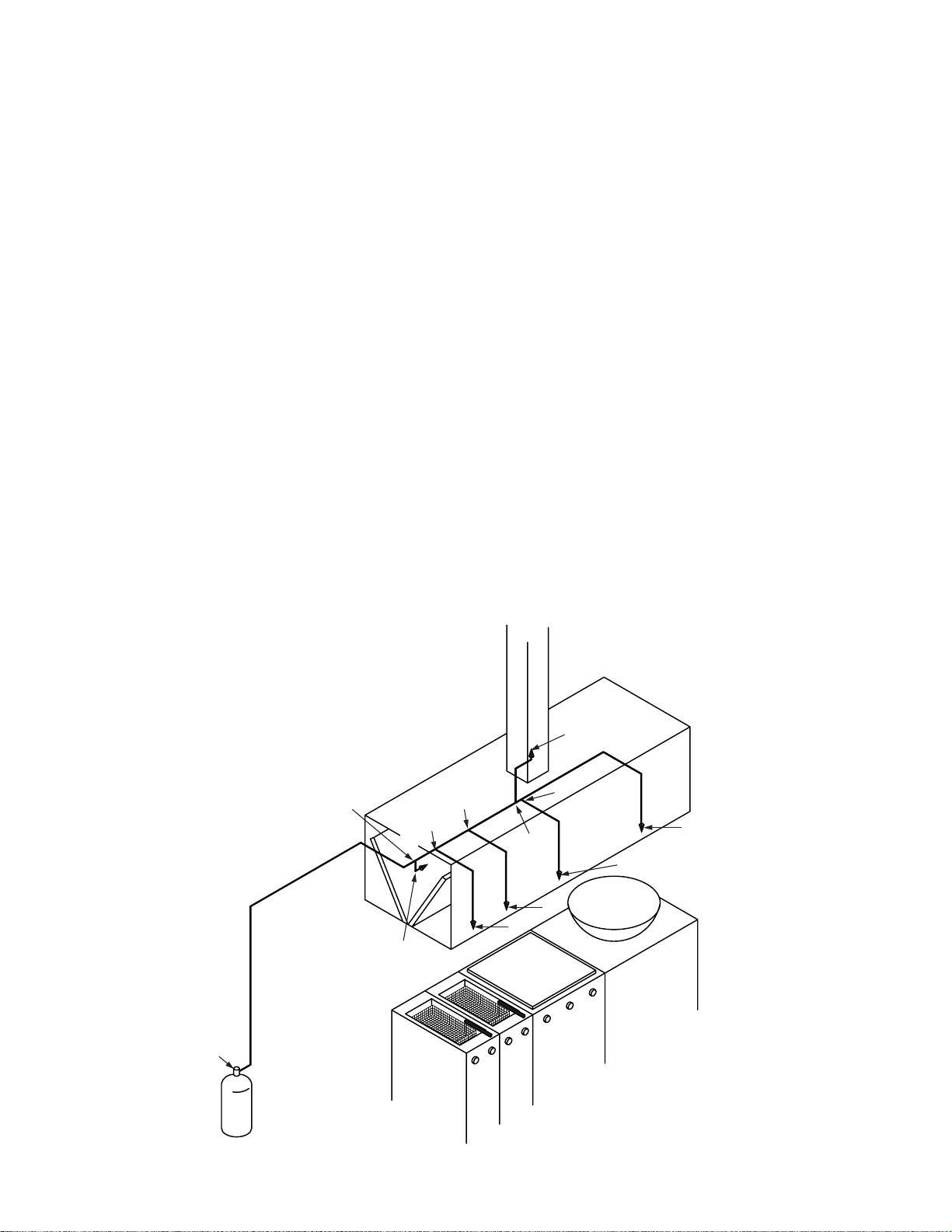
KITCHEN KNIGHT II Restaurant Fire Suppression Manual
SECTION 3 – SYSTEM DESIGN
UL EX3830 ULC EX3830
2014-NOV-10 REV. 06 PagE 3-21
Design Steps (Continued)
Step No. 4 Total all pipe lengths. Refer to Table 3-5: Volume.
Chose a given pipe size and multiply the ml per
foot by the total length of all the pipe. If the sum
falls within the acceptable range noted in Table
3-6: Tanks, that pipe size is acceptable. If the
calculated volume is too large, recalculate the
volume using the ml per foot of a smaller pipe size.
See Figure 3-37.
add section a-B = 0.5 ft + 5 ft + 14 ft + 2 ft +
0.5 ft = 22 ft (0.2 m + 1.5 m + 4.3 m + 0.6 m +
0.2 m = 6.8 m)
add section B-C = 1.5 ft (0.5 m)
add section C-D = 1 ft (0.3 m)
add section D-E = 2 ft (0.6 m)
add section E-F = 0.5 ft (0.2 m)
add section F-L = 3 ft + 2 ft + 2 ft = 7 ft (0.9 m +
0.6 m + 0.6 m = 2.1 m)
add section B-g = 0.5 ft (0.2 m)
add section C-H = 2 ft + 2 ft = 4 ft (0.6 + 0.6 =
1.2 m)
add section D-I = 2 ft + 2 ft = 4 ft (0.6 + 0.6 =
1.2 m)
add section E-J = 0.5 ft + 0.5 ft = 1 ft (0.15 m +
0.15 m = 0.3 m)
add section F-K = 2 ft + 2 ft = 4 ft (0.6 m + 0.6 m
= 1.2 m)
Total length of all pipe = 47.5 ft (14.5 m)
Refer to Table 3-5: Volume. The pipe size chosen
is 3/8 inch. The volume per foot of 3/8 in. pipe is
37.5 ml. Multiply 37.5 by the total pipe length of
47.5 ft.
37.5 ml x 47.5 ft = 1781 ml total volume
The maximum volume allowed for a PCL-300 is
1910 ml, therefore, 3/8 in. pipe is acceptable for
this system.
6
IN.
6 IN.
B
1.5
FT
6 IN.
14 FT
5 FT
A
6 FT
2 FT
G
D
2 FT
C
1 FT
2 FT
2 FT
2 FT
2 FT
H
J
3 FT
F
2 FT
E
2 FT
I
006193PC
2 FT
2 FT
L
k
FIGuRE 3-37
Page 48
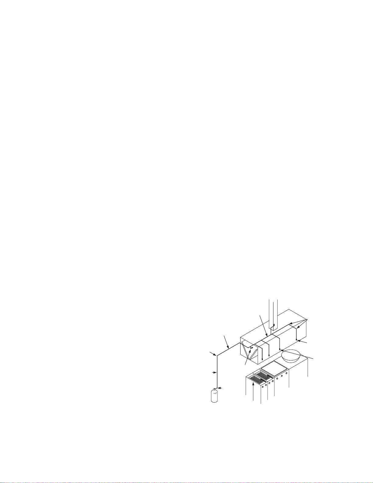
SECTION 3 – SYSTEM DESIGN
UL EX3830 ULC EX3830
PagE 3-22 REV. 06 2014-NOV-10
KITCHEN KNIGHT II Restaurant Fire Suppression Manual
Design Steps (Continued)
Step No. 5 Check to make certain minimum volumes and
maximum volume allowed between first nozzle and
last nozzle are not exceeded (Table 3-6: Tanks).
Check each rule in “general Piping Require ments”
on Page 3-19 to make certain none have been
exceeded. If any requirement is exceeded, change
to a different pipe size and recalculate. See Figure
3-38.
Refer to Table 3-6: Tanks
Minimum Pipe Volume for PCL-300 is 300 milli-
liters protecting a fryer, wok, or range (Example
system pipe volume is 1781 milliliters, therefore
OK)
Maximum Pipe Volume for PCL-300 is 1910
milliliters (Example system pipe volume is 1781
milliliters, therefore OK)
Maximum Volume Allowed Between First
Nozzle and Last Nozzle for PCL-300 is 1125
milliliters (Example system, the amount of 3/8 in.
piping between g and L, is 25.5 ft. and 25.5 ft x
37.5 mls/ft = 956.3 ml, therefore, OK)
Refer to General Piping Requirements
1. Split piping and straight piping are both
allowed on PCL-300 and PCL-460 systems.
(Example system OK)
2. PCL-600 systems must use split piping
only, with no nozzle located before the
split, and with a maximum of fourteen flow
points per side. 1/2 in. minimum piping
must be used up to the first split. (Example
system N/a)
3. Maximum volume for 1/4 in. pipe between
a nozzle and the preceding tee is 410 mls.
(Example system N/a)
4. Maximum flow numbers for 1/4 in. pipe is
six. (Example system N/a)
5. Maximum number of elbows between
a nozzle and the preceding tee is five.
(Example system has a maximum number of
two, therefore, OK)
6. Maximum of 25 elbows are allowed in the
total piping system. (Example system has 11
elbows, therefore, OK)
7. Maximum difference in elevation between
the tank outlet and any nozzle, or the tank
outlet and the highest or lowest horizontal
pipe run, is 10 ft (3.0 m) (Example system
has 5.5 ft (1.6 m), therefore, OK)
8. No traps are allowed in the piping network.
(Example system has no traps, therefore, OK)
9. Pipe lengths are measured from center
to center of fittings. (Example system pipe
lengths were measured from center to center
of fittings, therefore, OK)
10. The internal equivalent length volume of
fittings does not have to be considered
as part of the total pipe volume. (Example
system OK)
11. when utilizing different size pipe in the
total system, the largest size must start
first and the additional pipe must decrease
as it approaches the nozzle. (Example
system N/a)
12. Elbow(s) or swivel adaptors located at the
nozzles do not have to be counted in the
25 elbow maximum requirement. (Example
system OK)
13. Additional piping requirements when
protecting a range, wok, or a fryer:
• PCL-300 - Minimum of 300 ml and four
flow numbers required in total system.
Of that minimum, 239 ml and two flow
numbers must be utilized at or before the
range, wok, or fryer. (Example system has
1781 ml and ten flow numbers, therefore,
OK. The example system has 1050 ml and
three flows including the fryer, therefore,
OK)
• PCL-460 – Minimum of 660 ml and ten flow
numbers required in total system. Of that
minimum, 180 ml and two flow numbers
must be utilized at or before the range, wok,
or fryer.
• PCL-600 – Minimum of 960 ml and fourteen
flow numbers required in total system. Of
that minimum, 120 ml and two flow numbers
must be utilized at or before the range, wok,
or fryer.
GEN. PIPING
TANk CHART
MINIMUM/MaXIMUM
PIPE VOLUME
GEN.
PIPING
RULE
NO. 10
GEN.
PIPING
RULE
NO. 7
TANk CHART
MaX. VOL.
BETWEEN FIRST
aND LaST NOzzLE
RULE NO. 1, 8, 9
GEN. PIPING
RULE NO. 6
GEN. PIPING
RULE NO. 13
006193PC
GEN. PIPING
RULE NO. 5
TANk CHART
MaX. VOL.
BETWEEN
FIRST aND
LaST NOzzLE
GEN. PIPING
RULE NO. 12
FIGuRE 3-38
Page 49
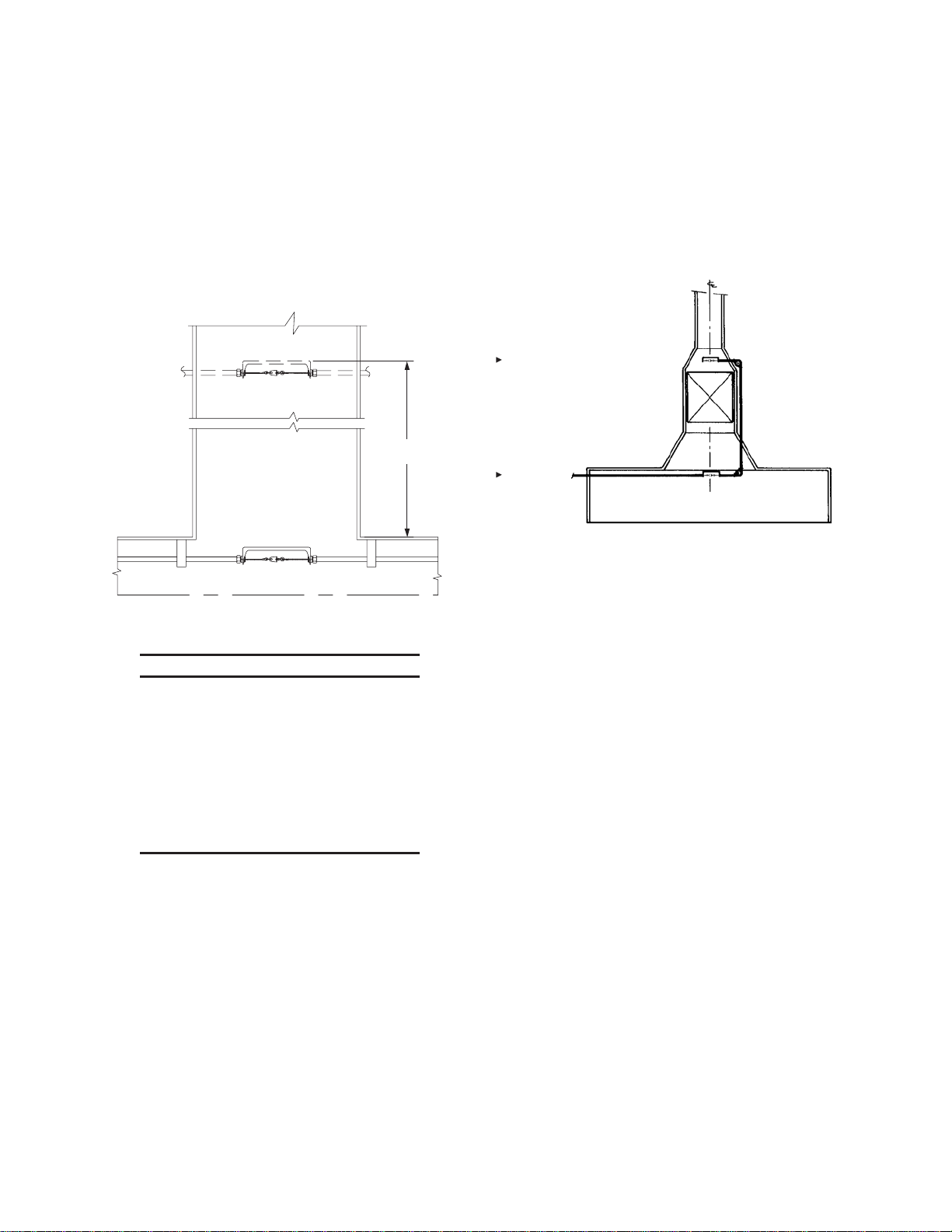
KITCHEN KNIGHT II Restaurant Fire Suppression Manual
SECTION 3 – SYSTEM DESIGN
UL EX3830 ULC EX3830
2014-NOV-10 REV. 06 PagE 3-23
DETECTOR PLACEMENT
Detectors are required over cooking appliances and in the
duct(s) of protected ventilation hoods.
Exhaust Duct(s)
Each exhaust duct must have at least one detector installed in
the duct entrance, located in the air stream of the cooking vapors
at a maximum of 12 ft (3.6 m) into the duct. See Figure 3-39.
12 FT (3.6 m)
MaXIMUM
Electrostatic Precipitator
If an electrostatic precipitator is located at or near the base of
the exhaust duct, it is necessary to locate a detector below the
precipitator, at the base of the duct, and also locate one in the
duct, just above the precipitator. See Figure 3-40.
When installing the detector bracket and system conduit, make
certain they do not interfere with the operation of the precipitator.
FIGuRE 3-40
000268
FIGuRE 3-39
NOTICE
When gas appliances are used and the flue
gases from the burner are exhausted into the
duct, the detector must be kept out of the air
stream of these exhaust gases. These gases
can be very hot and could actuate the system
unnecessarily .
Duct openings that are long and narrow or
large enough to require multiple duct nozzles
may require additional detectors.
006884PC
Page 50

SECTION 3 – SYSTEM DESIGN
UL EX3830 ULC EX3830
PagE 3-24 REV. 06 2014-NOV-10
DETECTOR PLACEMENT (Continued)
Cooking Appliance(s)
Each cooking appliance with a continuous cooking surface
not exceeding 48 in. x 48 in. (1219 mm x 1219 mm) shall be
protected by one detector. Cooking appliances with a continuous
cooking surface exceeding 48 in. x 48 in. (1219 mm x 1219 mm)
shall be protected by one detector per 48 in. x 48 in. (1219 mm
x 1219 mm) cooking area. Detectors used for cooking appliances must be located above the protected appliance toward
the exhaust duct side of the appliance. The detector should be
located in the air stream of the appliance to enhance system
response time.
If the cooking appliance is located under an exhaust duct where
a detector has been mounted, it is normally not necessary to
utilize another detector for that cooking appliance, provided the
detector is not more than 12 in. (304 mm) into the duct and the
appliance has no larger cooking surface than 48 in. x 48 in.
(1219 mm x 1219 mm). See Figure 3-41.
Note: If two appliances are located under a duct opening where
a detector has been mounted and both appliances together
do not exceed a cooking surface of 48 in. x 48 in. (1219 mm x
1219 mm) and the detector is located above both the protected
appliances, it is not necessary to utilize an additional detector
provided the duct detector is not more than 12 in. (304 mm) into
the duct opening.
KITCHEN KNIGHT II Restaurant Fire Suppression Manual
aPPLIaNCE
REqUIRES
SEPaRaTE
DETECTOR
aPPLIaNCE
COVERED BY
DETECTOR
UNDER DUCT
aPPLIaNCE
REqUIRES
SEPaRaTE
DETECTOR
FIGuRE 3-41
000269
Each cooking appliance with a continuous cooking surface
not exceeding 48 in. x 48 in. (1219 mm x 1219 mm) can be
protected by a minimum of one detector. Cooking appliances
with a continuous cooking surface exceeding 48 in. x 48 in.
(1219 mm x 1219 mm) must be protected by at least one
detector per 48 in. x 48 in. (1219 mm x 1219 mm) cooking
area. Detectors used for cooking appliances must be located
above the protected appliance toward the exhaust duct side of
the appliance. The detector should be located in the air stream
of the appliance to enhance system response time.
Page 51
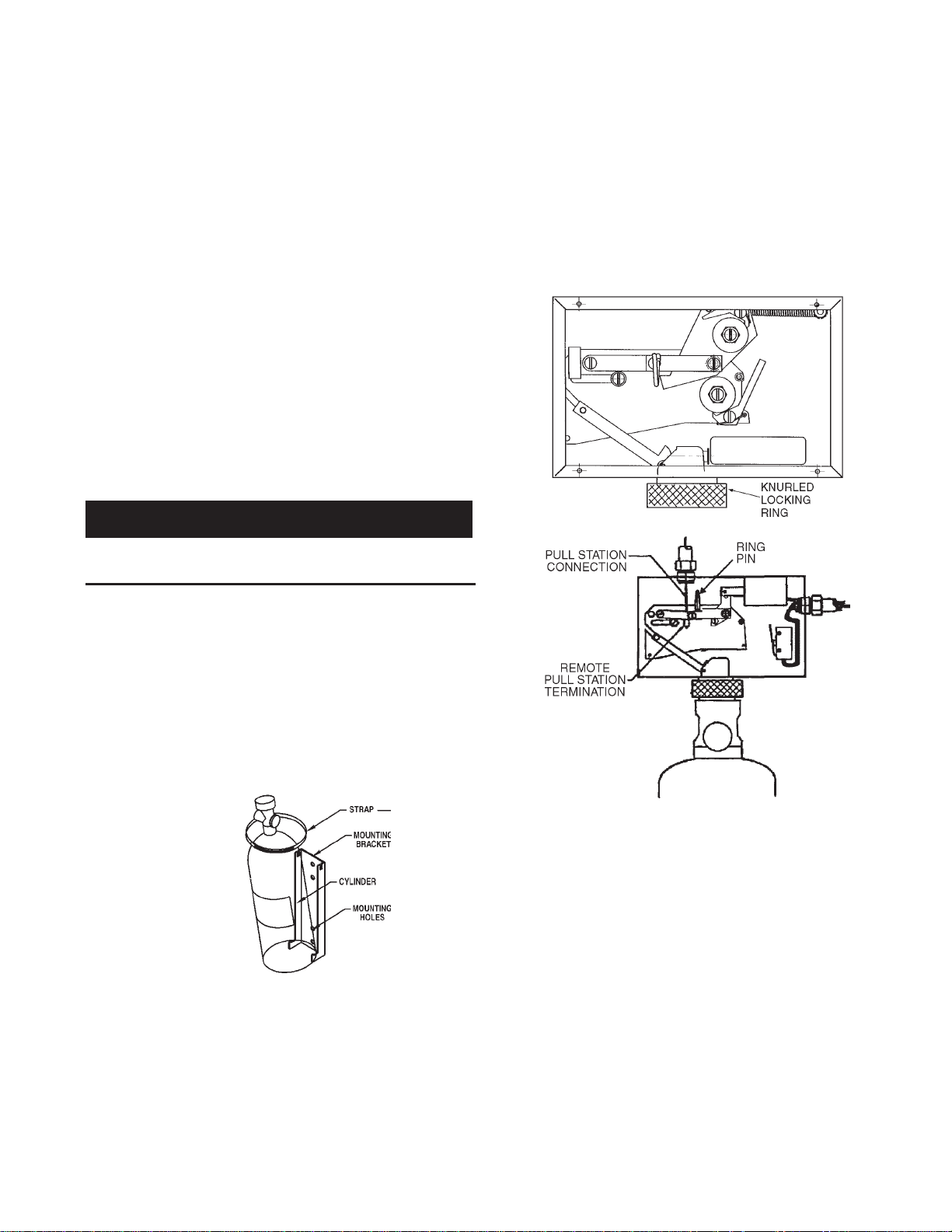
KITCHEN KNIGHT II Restaurant Fire Suppression Manual
SECTION 4 – SYSTEM INSTALLATION
UL EX3830 ULC EX3830
2014-NOV-10 REV. 06 PagE 4-1
GENERAL
The installation information listed in this section deals with the
limitations and parameters of this pre-engineered system. Those
individuals responsible for the installation of the KITCHEN
KNIgHT II system must be trained and hold a current PYROCHEM certificate in a KITCHEN KNIgHT II training program.
Pipe and fittings for the discharge piping, conduit (EMT),
pipe straps, pipe hangers, mounting bolts, and other
miscellaneous equipment are not furnished as part of the
PYRO-CHEM KITCHEN KNIgHT II Restaurant Fire Suppression
System. These items must be furnished by the installer.
Before attempting any installation, unpack the entire system and
check that all necessary parts are on hand. Inspect parts for
damage. Verify that cylinder pressure is within the acceptable
range as shown on the gauge.
CYLINDER INSTALLATION
The cylinder and valve assembly is shipped with an anti-recoil
plug in the valve discharge port.
CAUTION
The anti-recoil plug must remain in the valve discharge port
until the discharge piping is connected to the valve.
CONTROL HEAD INSTALLATION
Single Cylinder Installation
For single cylinder system installations the Model MCH3/ECH3/
NMCH3 Control Head can be installed directly onto the cylinder
valve. When the control head is properly aligned in the desired
position, tighten the knurled locking ring to secure the assembly.
See Figure 4-2.
The cylinder must be mounted vertically. The Models PCL-300
and PCL-460 cylinders must be mounted using a Model MB-15
Mounting Bracket Kit. The Model PCL-600 cylinder must be
mounted using a Model MB-1 Mounting Bracket Kit.
The bracket must be securely anchored to the wall using bolts
or lag screws. The wall to which the bracket is attached must
be sufficiently strong to support the cylinder. The bracket should
never be fastened to dry wall or similar material. If this type of
wall is encountered, studs must be located and the bracket
fastened to them. See Figure 4-1.
FIGURE 4-1
002945PC
FIGURE 4-2
006214PC / 003647PC
Page 52
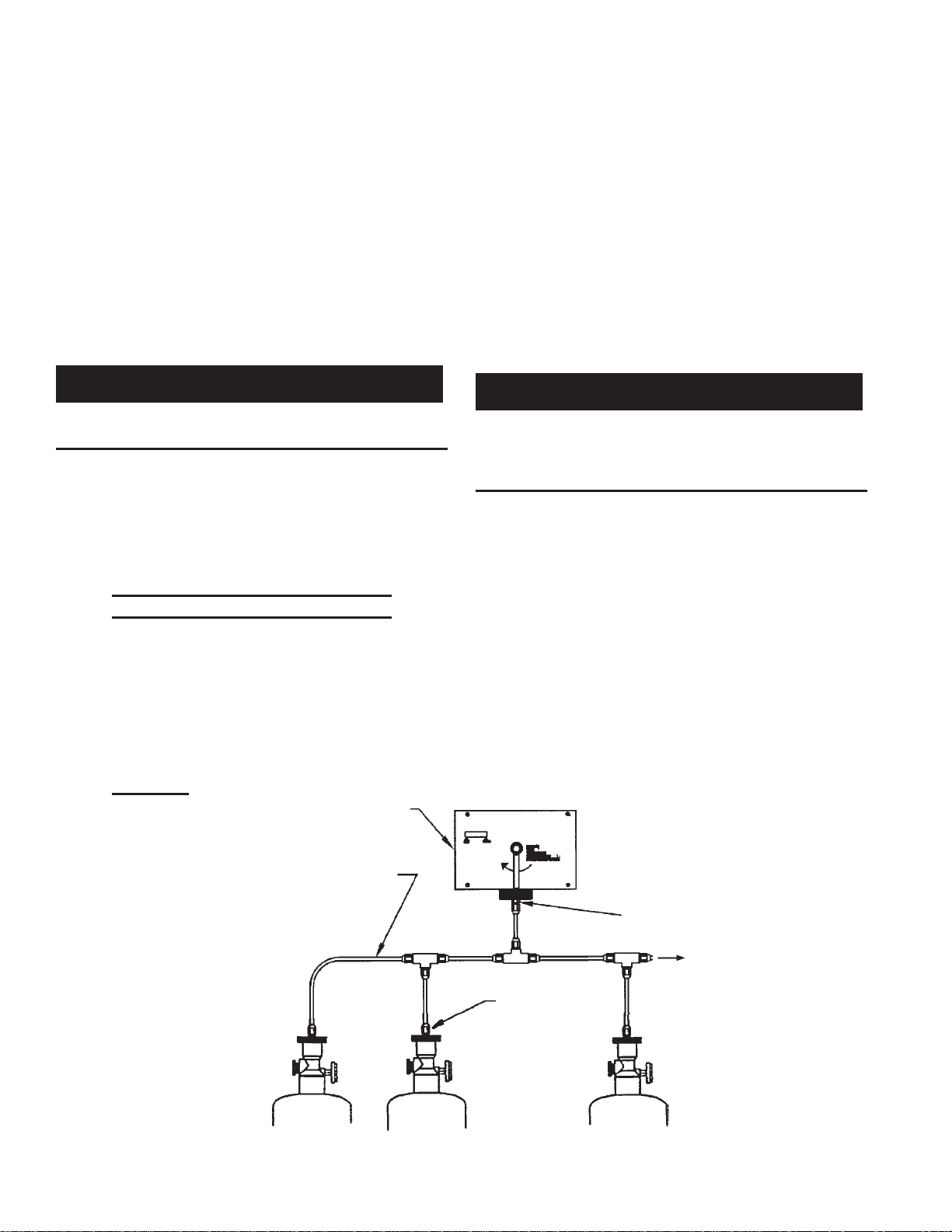
SECTION 4 – SYSTEM INSTALLATION
UL EX3830 ULC EX3830
PagE 4-2 REV. 06 2014-NOV-10
CONTROL HEAD INSTALLATION (Continued)
Multiple Cylinder Installation
1. Multiple Cylinder actuation Using MCH3/ECH3/NMCH3
Control Head
The Model MCH3/ECH3/NMCH3 Control Head can be used to
pneumatically actuate a maximum of five agent cylinders with a
16 gram CO2 cartridge. When a control head is used for multiple
cylinder actuation, it cannot be mounted directly onto a cylinder
valve. The control head must be installed remotely using a
Model MB-P2 Control Head Mounting Bracket. The bracket must
be anchored to the wall using bolts or lag screws.
KITCHEN KNIGHT II Restaurant Fire Suppression Manual
a single Model MCH3/ECH3/NMCH3 Control Head can actuate:
1. Up to four cylinders with a maximum of 25 ft (7.6 m) of
copper or stainless steel pneumatic tubing or stainless
steel actuation hose when using an o-ring (Part No. 55531)
installed in place of the Teflon washer and the 16 gram CO2
cartridge.
2. Up to five cylinders with a maximum of 18 ft (5.4 m) of
copper or stainless steel pneumatic tubing or stainless
steel actuation hose when using an o-ring (Part No. 55531)
installed in place of the Teflon washer and the 16 gram CO
2
cartridge.
CAUTION
Do not screw the control head directly to a wall as this will warp
the control head, not allowing the mechanism to actuate.
In order to actuate the agent cylinder(s) from a control head, a
1/4 in. NPT x 45° 1/4 in. flare type fitting (conforming to SaE
J513c) or Male Straight Connector (Part No. 32338) must be
screwed into the base of the control head actuator. Pneumatic
tubing or stainless steel actuation hose is then used to connect
the control head to the valve cap assembly of each agent cylinder valve. See Figure 4-3.
NOTICE
Pneumatic tubing (copper) used for remote
cylinder actuation shall have an outside diameter of 1/4 in. with a minimum wall thickness
of 1/32 in. (0.8 mm). This is commonly known
as refrigeration-type copper tubing. all tubing
fittings shall be of the 1/4 in., 45° flare type
conforming to SaE J513c.
Compression type fittings are not acceptable.
MCH3, NMCH3, OR ECH3
CONTROL HEaD
CAUTION
Confirm the Teflon washer in the control head actuator assembly has been replaced with the o-ring (Part No. 55531) and the
16 gram CO2 cartridge is installed for four and five cylinder
single control head actuation.
The actuation line must be tested for any leaks by using a hand
held or electric vacuum pump. The pump should be used to draw
a vacuum on the actuation line at the fitting closest to the control
head. a vacuum should be pulled to 20 in. (508 mm) of mercury.
Leaks exceeding 5 in. (127 mm) of mercury within 30 seconds
are not allowed. If the gauge on the vacuum pump indicates a
leak in the line, examine the actuation line for loose fittings or
damage. Correct any leaks and retest.
1/4 IN. OD COPPER TUBINg OR S.S. aCTUaTION HOSE
MaX. 18 FT (5.4 m) FOR FIVE CYLINDER aCTUaTION
45° 1/4 IN. FLaRED
TUBINg NUT WITH
COPPER TUBINg
1/4 IN. NPT X 45° 1/4 IN. FLaRE TYPE
FITTINg (SaE J513c) OR MaLE STRaIgHT
CONNECTOR (PaRT NO. 32338)
TO REMaININg
CYLINDERS
FIGURE 4-3
004428PC
Page 53
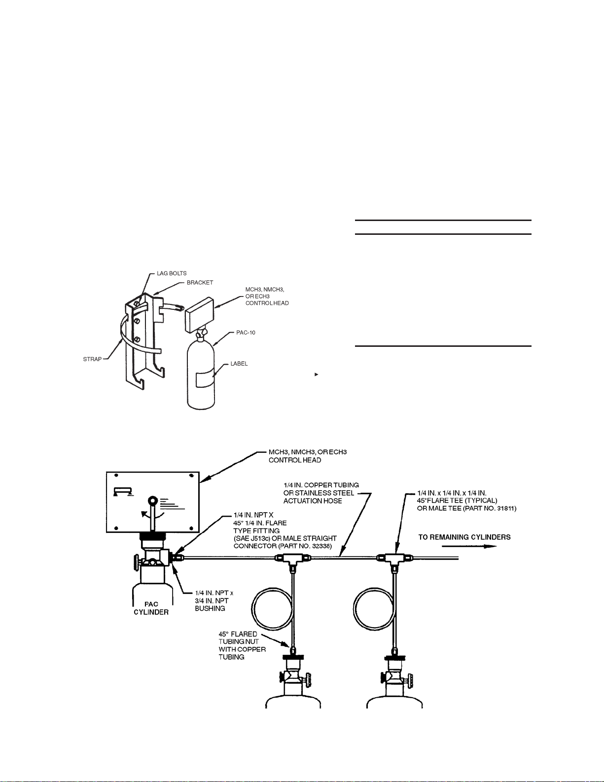
KITCHEN KNIGHT II Restaurant Fire Suppression Manual
CONTROL HEAD INSTALLATION (Continued)
2. Multiple Cylinder actuation Using Model PaC-10 Pneumatic
actuation Cylinder
The Model PaC-10 Pneumatic actuation Cylinder must be used
if more than five agent cylinders require simultaneous actuation. The Model PaC-10 must be used in conjunction with a
Model MCH3/ECH3/NMCH3 Control Head. The control head is
mounted on the Model PaC-10 valve assembly.
The Model PaC-10 is shipped complete with a mounting bracket.
The bracket must be securely anchored to the wall using bolts
or lag screws. The wall to which the bracket is attached must
be sufficiently strong to support the pneumatic cylinder. The
bracket should never be fastened to dry wall or similar material.
If this type of wall is encountered, studs must be located and the
bracket fastened to them. See Figure 4-4.
SECTION 4 – SYSTEM INSTALLATION
UL EX3830 ULC EX3830
2014-NOV-10 REV. 06 PagE 4-3
In order to actuate the agent cylinders from a Model PaC-10
Pneumatic actuation Cylinder, a 3/4 in. NPT x 1/4 in. NPT
bushing must be screwed into the pneumatic cylinder’s discharge
port. a 1/4 in. NPT x 45° 1/4 in. flare type fitting (conforming to
SaE J513c) must then be screwed into this bushing. The Male
Straight Connector (Part No. 32338) is used with stainless steel
actuation hose. Pneumatic tubing or stainless steel actuation
hose is then used to connect the PaC-10 pneumatic cylinder
to the valve cap assembly of each agent cylinder valve. See
Figure 4-5.
NOTICE
Pneumatic tubing (copper) used for remote
cylinder actuation shall have an outside diameter of 1/4 in. with a minimum wall thickness
of 1/32 in. (0.8 mm). This is commonly known
as refrigeration-type copper tubing. all tubing
fittings shall be of the 1/4 in., 45° flare type
conforming to SaE J513c.
Compression type fittings are not acceptable.
FIGURE 4-4
002874PC
The Model PaC-10 pneumatic cylinder can actuate a maximum
of ten agent cylinders with a maximum of 100 ft (30.4 m) of
pneumatic tubing.
FIGURE 4-5
004427PC
Page 54
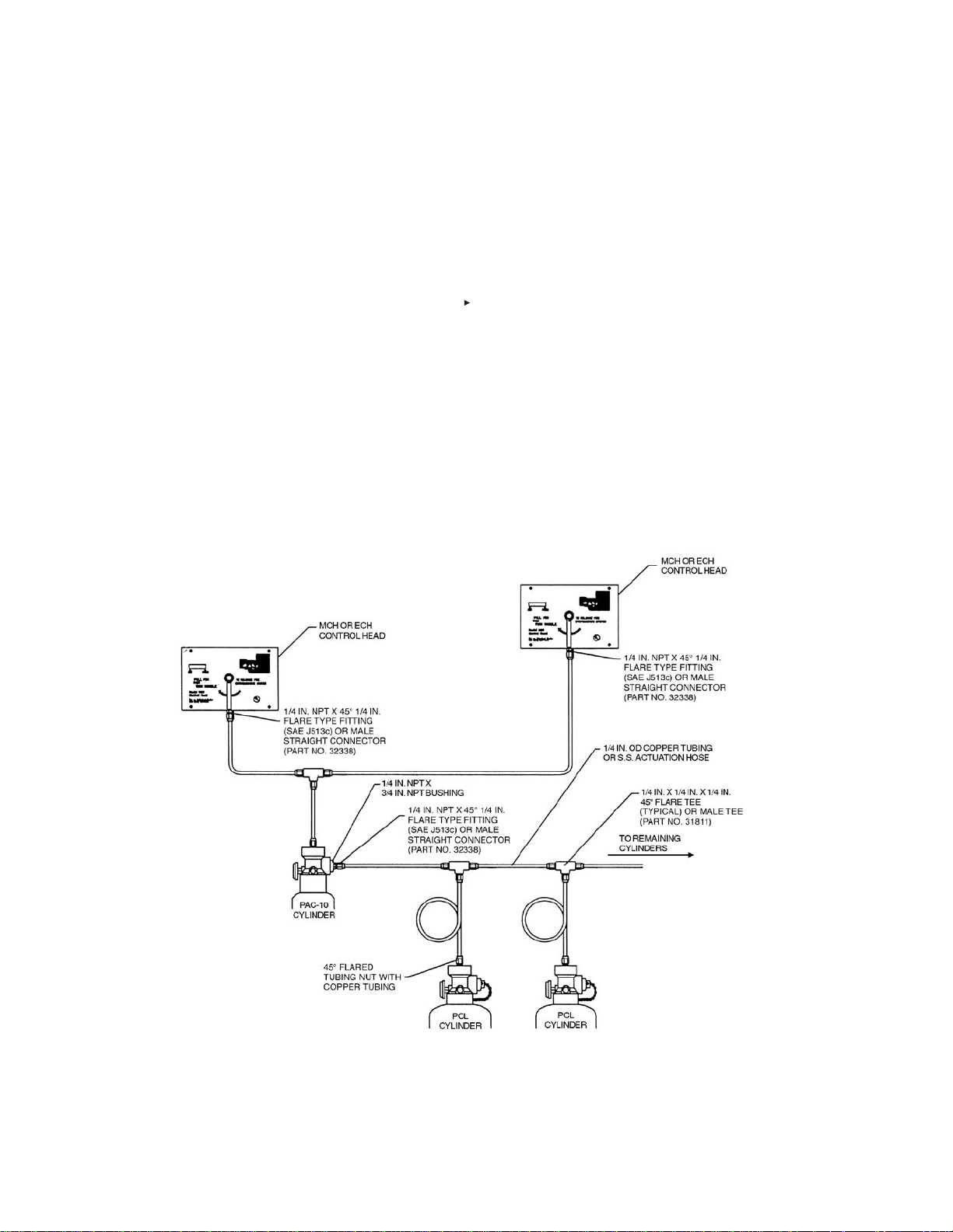
SECTION 4 – SYSTEM INSTALLATION
UL EX3830 ULC EX3830
PagE 4-4 REV. 06 2014-NOV-10
KITCHEN KNIGHT II Restaurant Fire Suppression Manual
CONTROL HEAD INSTALLATION (Continued)
2. Multiple Cylinder actuation Using Model PaC-10 Pneumatic
actuation Cylinder (Continued)
If the system design requires the use of two control heads for
multiple cylinder actuation, a maximum of 25 ft (7.6 m) of tubing
is allowed between the two control heads and the PaC-10 cylinder. See Figure 4-6. If a PaC-10 cylinder is not utilized, there is
a maximum of 25 ft (7.6 m) of tubing for the two control heads
and up to four cylinders or a maximum of 18 ft (5.4 m) of tubing
for the two control heads and five cylinders.
DETECTOR INSTALLATION
Fusible Link Detection
Fusible links are always used in conjunction with the Model
MCH3 Mechanical Control Head. after mounting the cylinder
and control head, the fusible link line can be installed. The first
step to installing the fusible link line is to install the detector
bracket(s) over all protected appliances and in each duct. See
Section 3 – System Design for detector placement guidelines.
Note: Only A-PC-style Fusible Links can be used.
Connect the fusible link brackets together using 1/2 in. conduit
and the conduit connectors supplied in the detector kit (Model
FLK-1). a PYRO-CHEM KITCHEN KNIgHT II corner pulley
must be used whenever a change in conduit direction is necessary. The conduit is connected to the control head through a
knockout in the upper left-side corner.
In general, fusible links centered in the detector brackets are
connected in series using 1/16 in. (1.6 mm) diameter stainless
steel cable. The spring plate in the control head maintains
tension on this series of fusible links. If the tension is released
for any reason (e.g. a fusible link separates), the control head
will operate and actuate the system.
FIGURE 4-6
006858
Page 55
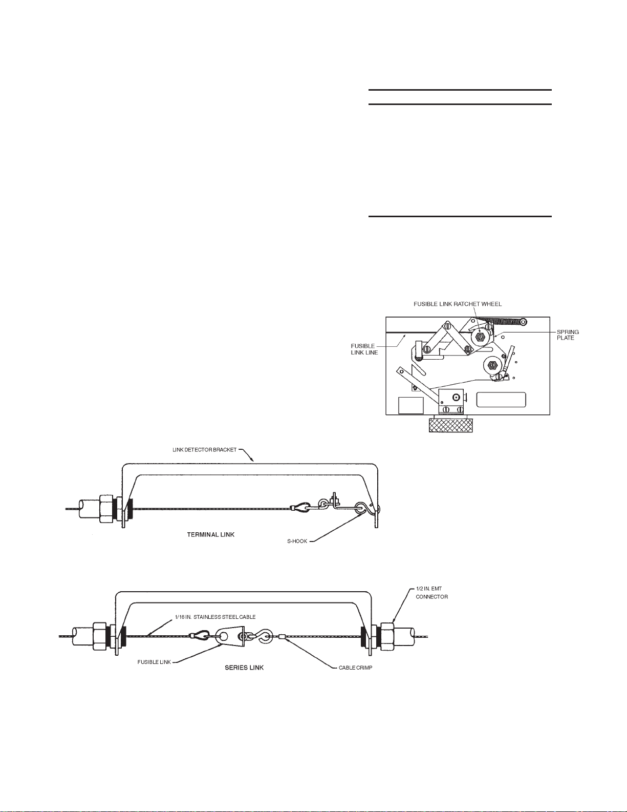
KITCHEN KNIGHT II Restaurant Fire Suppression Manual
SECTION 4 – SYSTEM INSTALLATION
UL EX3830 ULC EX3830
2014-NOV-10 REV. 06 PagE 4-5
DETECTOR INSTALLATION (Continued)
Fusible Link Detection (Continued)
Maximum limitations for the fusible link detection line are as
follows:
Fusible links can be installed with or without fusible link hangers
(see Section 2 – Components for description).
Fusible Link Line Limitations When Used with Model
EN-MCU3, MCH3, and NMCH3 Control Heads and CBP-1,
SBP-1, and WBP-1 Pulley Elbows
Maximum # of detectors: 20
Maximum length of cable: 150 ft (45.7 m)
Maximum # of pulleys: 40
Fusible Links Without Hangers
Begin installing links at the terminal bracket. The link is
connected to the far side of the terminal bracket using an “S”
hook. The “S” hook must be crimped closed after the link is
installed. a tight loop is then made in the cable and secured
by the crimp provided. This loop is connected to the other side
of the terminal link (see Figure 4-7) and the cable fed through
the conduit to the next bracket. The cable proceeding from the
terminal link will be used to connect the series links (see Figure
4-8). Series links must be centered in their detector brackets.
after the last link in the series is connected, the cable should
be fed through the conduit back to the control head. Thread
the cable through the hole in the fusible link ratchet wheel. The
line must then be crimped, and the crimp positioned inside the
center of the ratchet wheel.
NOTICE
Crimps must always be used in conjunction with two cable lengths. Loops are the
accepted method of connecting the cable to
mechanical components. The crimp must
never be used on a single cable. Exception:
Single cable crimp allowed in detection and
gas valve ratchet wheel using Stop Sleeve
(Part No. 26317) (Packages of 10: Part No.
24919).
The fusible link line can now be put into a set position by applying tension to the fusible link line. This is accomplished by using
a 1/2 in. hex wrench on the fusible link line ratchet wheel. The
ratchet wheel will be ratcheted in a clockwise direction until the
spring plate makes contact with the top of the control head box.
The fusible link line is now in a set position. See Figure 4-9.
FIGURE 4-9
006215PC
FIGURE 4-7
002849aPC
FIGURE 4-8
002849bPC
Page 56
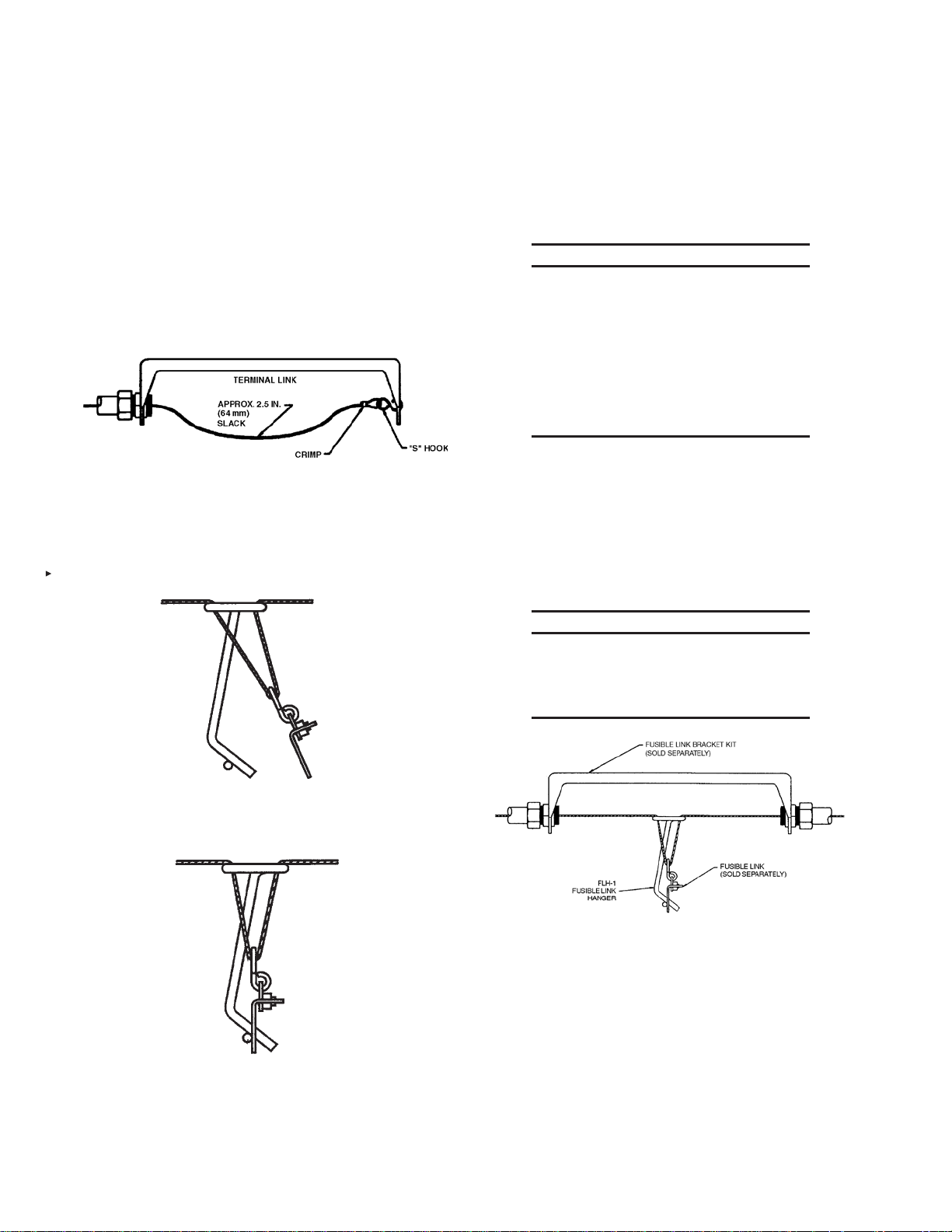
SECTION 4 – SYSTEM INSTALLATION
UL EX3830 ULC EX3830
PagE 4-6 REV. 06 2014-NOV-10
DETECTOR INSTALLATION (Continued)
Fusible Link Installation Using Model FLH-1 Fusible Link
Hangers
Beginning at the control head, feed the stainless steel cable
through the conduit and brackets to the terminal bracket in one
continuous length. allow approximately 2.5 in. (64 mm) of slack
at each bracket for the installation of the fusible link hangers. at
the terminal link, a tight loop is made in the cable and secured
by the crimp provided. The cable is attached to the far side of
the terminal bracket using an “S” hook. The “S” hook must be
crimped closed after the cable is installed. See Figure 4-10.
KITCHEN KNIGHT II Restaurant Fire Suppression Manual
after the last hanger/link in the series is connected, the cable
should be fed through the hole in the fusible link ratchet wheel.
The line must then be crimped, and the crimp positioned inside
the center of the ratchet wheel.
NOTICE
Crimps must always be used in conjunction with two cable lengths. Loops are the
accepted method of connecting the cable
to mechanical components. The crimp must
never be used on a single cable. Exception:
Single cable crimp allowed in detection and
gas valve ratchet wheel using Stop Sleeve
(Part No. 26317) (Packages of 10: Part No.
24919).
FIGURE 4-10
002877PC
Begin installing the fusible link hangers at the terminal bracket
and work toward the control head. Loop the cable through the
oval opening in the hanger and hook the fusible link on the loop.
See Figure 4-11.
Note: Only A-PC-style Fusible Links can be used.
FIGURE 4-11
002878PC
Hook the bottom of the link onto the bottom leg of the hanger.
See Figure 4-12.
The fusible link line can now be put into a set position by applying tension to the fusible link line. This is accomplished by using
a 1/2 in. hex wrench on the fusible link line ratchet wheel. The
ratchet wheel will be ratcheted in a clockwise direction until the
spring plate makes contact with the top of the control head box.
The fusible link line is now in a set position. See Figure 4-9.
Check to ensure that the fusible link hanger(s) remain centered
in the bracket after the fusible link line is set. See Figure 4-13.
NOTICE
If wire rope requires splicing, a splice is to
be a minimum of 12 in. (305 mm) from any
pulley elbow or conduit adaptor to avoid
interference.
FIGURE 4-12
002879PC
Center the hanger/link in the fusible link bracket by sliding
it along the link line. This is easily accomplished before any
tension is applied to the link line. Repeat this procedure for all
fusible links.
FIGURE 4-13
002849bPC
Thermal Detection
Thermal detectors are always used in conjunction with the
Model ECH3 Electrical Control Head. after mounting the cylinder and control head, the thermal detector(s) can be installed.
Install the thermal detector(s) in the plenum area of the ventilation hood over all protected appliances and in each duct. See
Section 3 – System Design for detector placement guidelines.
Follow the instructions included with the detector for proper
detector mounting procedures.
Page 57
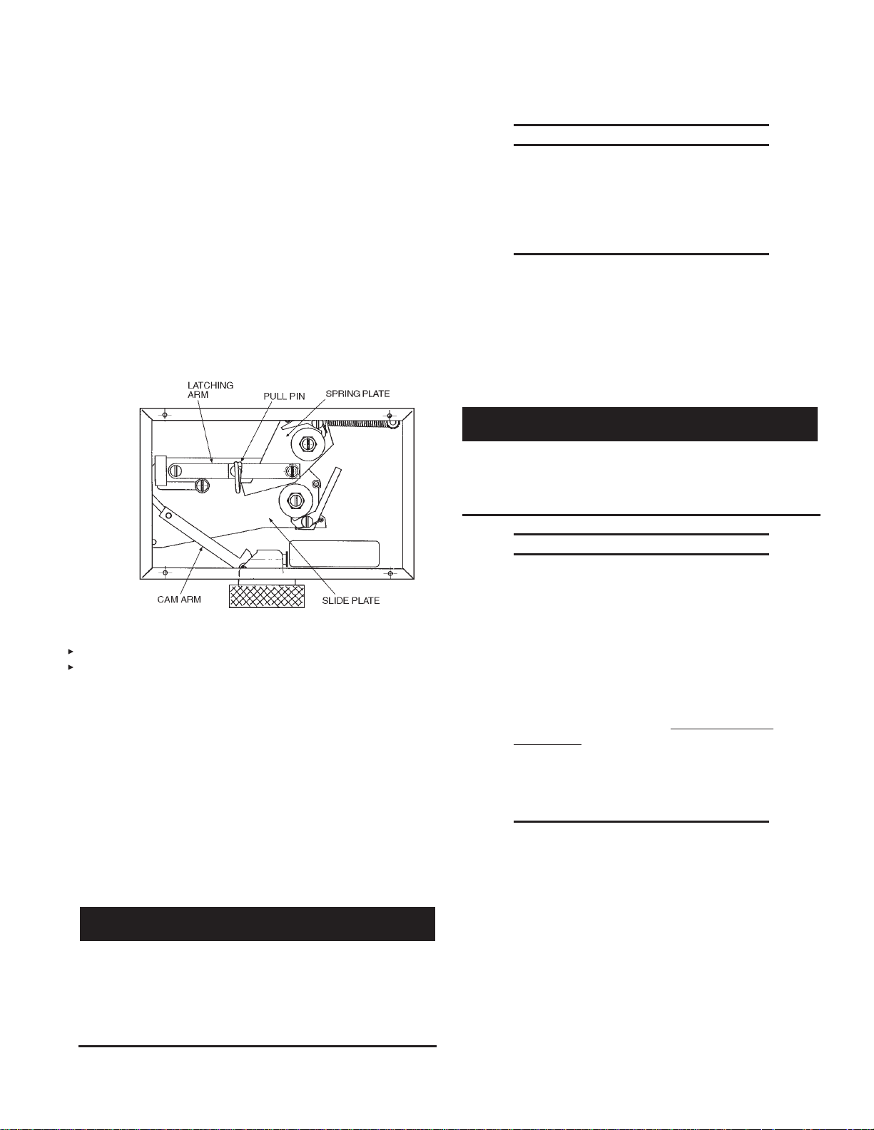
KITCHEN KNIGHT II Restaurant Fire Suppression Manual
SECTION 4 – SYSTEM INSTALLATION
UL EX3830 ULC EX3830
2014-NOV-10 REV. 06 PagE 4-7
SETTING THE CONTROL HEAD
Model MCH3/NMCH3 Mechanical Control Head
Once the fusible link line is set, the control head can be placed in
the set position. Set the control head using the proper procedure
of ratcheting the detection line to raise the spring plate parallel
to the top of the control head box prior to placing the latching
arm in the slide plate. The slide plate is moved from right to
left, ensuring the bolt extending from the cam arm is in the slot
provided in the slide plate. Continue moving the slide plate to
the left until the latching arm is in the locked position. Insert the
pull pin into the hole in the slide plate above the latching arm.
This will lock the control head in the set position, eliminating
accidental actuation during the rest of the installation procedure.
See Figure 4-14.
NOTICE
No electrical connections shall be made
inside the con trol head. all electrical wiring
shall exit the control head through the knockout on the side of the box. all electrical
connections must be made in an approved
electrical box.
Connect one of the black wires on the solenoid in the control
head to the red wire of the Model MS-SPDT Electrical (snap-action) Switch. The brown wire from the electrical (snap-action)
switch is then connected to one side of the first thermal detector
in series. Connect the other side of the first thermal detector
in series and the remaining black wire on the solenoid in the
control head to the appropriate power source after installing the
Model SM-120 Solenoid Monitor.
CAUTION
The solenoid must never be wired “hot” (not through the
electrical (snap-action) switch). If wired this way, the non-field
replaceable solenoid will be damaged and the complete
control head will require replacement.
NOTICE
FIGURE 4-14
Note: Tension must be set on fusible link detection line before
control head can be set.
Model ECH3 Electrical Control Head
Once the thermal detectors have been installed, the control
head can be placed in the set position. To set the control head,
the slide plate is moved from right to left, ensuring the bolt
extending from the cam arm is in the slot provided in the slide
plate. Continue moving the slide plate to the left until the latching
arm is in the locked position. Insert the pull pin into the hole in
the slide plate above the latching arm. This will lock the control
head in the set position, eliminating accidental actuation during
the rest of the installation procedure.
Once the Model ECH3 Electrical Control Head is in the set
position, it can be connected to the detection/actuation circuit.
WARNING
!
Before working on any electrical wiring, make certain main
power has been disconnected. Failure to disconnect main
power could cause personal injury or death if contact is made
with energized wires. all electrical wiring and connections to be
made in accordance with the authority having jurisdiction and
all local electrical codes.
006219PC
a Model SM-120 Solenoid Monitor must
always be used with an Electrical Control
Head to supervise the actuation/detection
circuit.
Where electrical detection and/or actuation
is provided, supervision shall be provided in
accordance with NFPa-17a.
alarms and indicators along with a supervised
backup power source shall be provided in
accordance with NFPa 72, The National Fire
alarm Code.
Electrical wiring and equipment shall be
installed in accordance with NFPa 70,
National Electric Code or the requirements of
the authority having jurisdiction.
The Model ECH3-24 Electrical Control Head requires a 24VDC
power supply with a minimum 2a rating. The Model ECH3-120
Electrical Control Head requires a 1a, 120VaC power supply.
Page 58
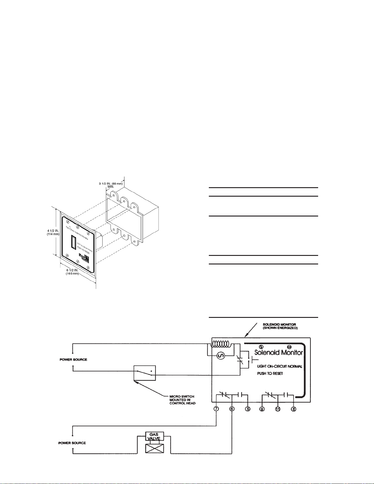
SECTION 4 – SYSTEM INSTALLATION
UL EX3830 ULC EX3830
PagE 4-8 REV. 06 2014-NOV-10
SOLENOID MONITOR INSTALLATION
Solenoid Monitor Installation in Detection Circuit
after installing the thermal detectors and the control head, the
Model SM-120 Solenoid Monitor can be installed. The Solenoid
Monitor is connected to the wires leading from the last thermal
detector. It should be mounted in a location where it can be
readily observed.
The Solenoid Monitor is an end-of-line device that supervises
the actuation/detection circuit. It is comprised of a push-type
switch with a built-in indicator light, a plug-type relay, a relay
socket, and a cover plate. The light, when illuminated, indicates
that the detection/actuation circuit is in the normal condition. The
Solenoid Monitor also provides two sets of dry contacts. The
Solenoid Monitor’s cover plate is used to mount the Solenoid
Monitor in a standard 6 in. x 4 in. x 3 in. (152 mm x 102 mm x
76 mm) deep electrical box. See Figure 4-15.
KITCHEN KNIGHT II Restaurant Fire Suppression Manual
all wire for circuits using the Model SM-120 shall be 14 gauge
minimum, or as required by local code.
after the Solenoid Monitor has been installed, the detection/
actuation circuit can be connected to the appropriate power
source and energized. To energize the detector/actuation
circuit, depress the switch on the Solenoid Monitor. The light will
illuminate to indicate that the circuit is properly installed. If the
light fails to illuminate, the wiring must be checked.
Solenoid Monitor When Used as a Reset Relay
The Model SM-120 can be used as a reset relay when required.
a reset relay is required whenever an electrical gas shut-off
valve is used in conjunction with the PYRO-CHEM KITCHEN
KNIgHT II Restaurant Fire Suppression System. For typical
wiring connections, see Figure 4-16.
REMOTE PULL STATION INSTALLATION
NOTICE
FIGURE 4-15
002881PC
For flexible conduit/pull station installation
instructions, refer to Pages 4-21 through 4-30.
The Model RPS-M Remote Mechanical Pull Station is used for
remote mechanical actuation of all system releasing devices.
It is to be located near an exit in the path of egress from the
hazard area no more than 4 ft (1.2 m) above the floor.
NOTICE
a Model RPS-M Remote Mechanical Pull
Station must be used for manual activation
of a Model EN-MCU3 or a Model NMCH3
releasing device. If the PYRO-CHEM
Releasing Panel is being utilized, then the
RPS-E2 Electric Pull Station may be used for
manual activation.
FIGURE 4-16
002882PC
Page 59
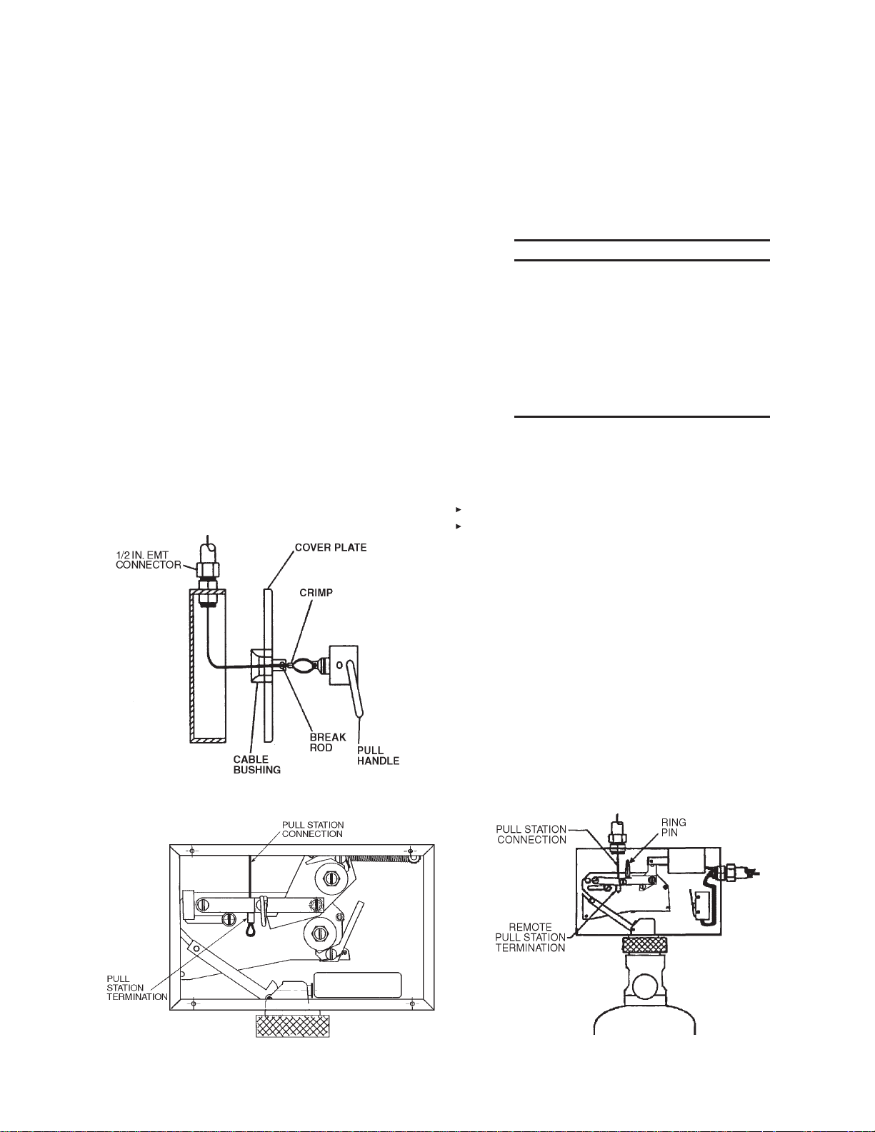
KITCHEN KNIGHT II Restaurant Fire Suppression Manual
REMOTE PULL STATION INSTALLATION (Continued)
The Pull Station can be surface mounted or flush mounted.
For flush mounting a RaCO #232 4 in. (102 mm) deep electrical box or equivalent must be used (dealer supplied). It is
connected to the releasing device using 1/16 in. (1.6 mm)
diameter stainless steel cable. The cable enters the pull station
box through the center hole in the bottom, top, either side,
or the center back hole. The cable enters the control head
through the top-center knockout. The cable must be enclosed in
1/2 in. EMT conduit with a PYRO-CHEM KITCHEN KNIgHT
II corner pulley at each change in conduit direction. Maximum
limitations for the Model RPS-M Remote Mechanical Pull Station
are as follows:
Model RPS-M Cable Run Limitations When Used with
Model ECH3, MCH3, EN-MCU3, and NMCH3 Control Heads
and CBP-1, SBP-1, and WBP-1 Pulley Elbows
Maximum length of cable: 150 ft (45.7 m)
Maximum # of pulleys: 40
after mounting the pull station box and conduit, feed the stainless steel cable from the releasing device, through the conduit,
and into the pull station box. Feed the cable through the bushing
and through the hole provided in the pull handle. Loop the cable
through the pull handle and secure it with the crimp provided
(see Figure 4-17).
SECTION 4 – SYSTEM INSTALLATION
UL EX3830 ULC EX3830
2014-NOV-10 REV. 06 PagE 4-9
Cut and thread the cable through the hole in the latching arm
of the control head and pull the cable tight. Crimp the cable
approximately 6 in. to 8 in. (152 mm to 203 mm) below the
latching arm. Note: NFPa-17a requires the pull length to be no
more than 14 in. (355 mm).
NOTICE
Crimps must always be used in conjunction with two cable lengths. Loops are the
accepted method of connecting the cable
to mechanical components. The crimp must
never be used on a single cable. Exception:
Single cable crimp allowed in detection and
gas valve ratchet wheel using Stop Sleeve
(Part No. 26317) (Packages of 10: Part No.
24919).
Pull the pull handle until the crimp touches the latching arm. See
Figure 4-18. Coil the excess cable in the pull box and attach the
cover plate with the four screws provided. Insert the pull handle
into the cover plate and insert the plastic break rod.
Note: Excess wire rope must be coiled in the pull station box,
not in the control head.
FIGURE 4-17
002884PC
FIGURE 4-18
006216PC/003647PC
Page 60
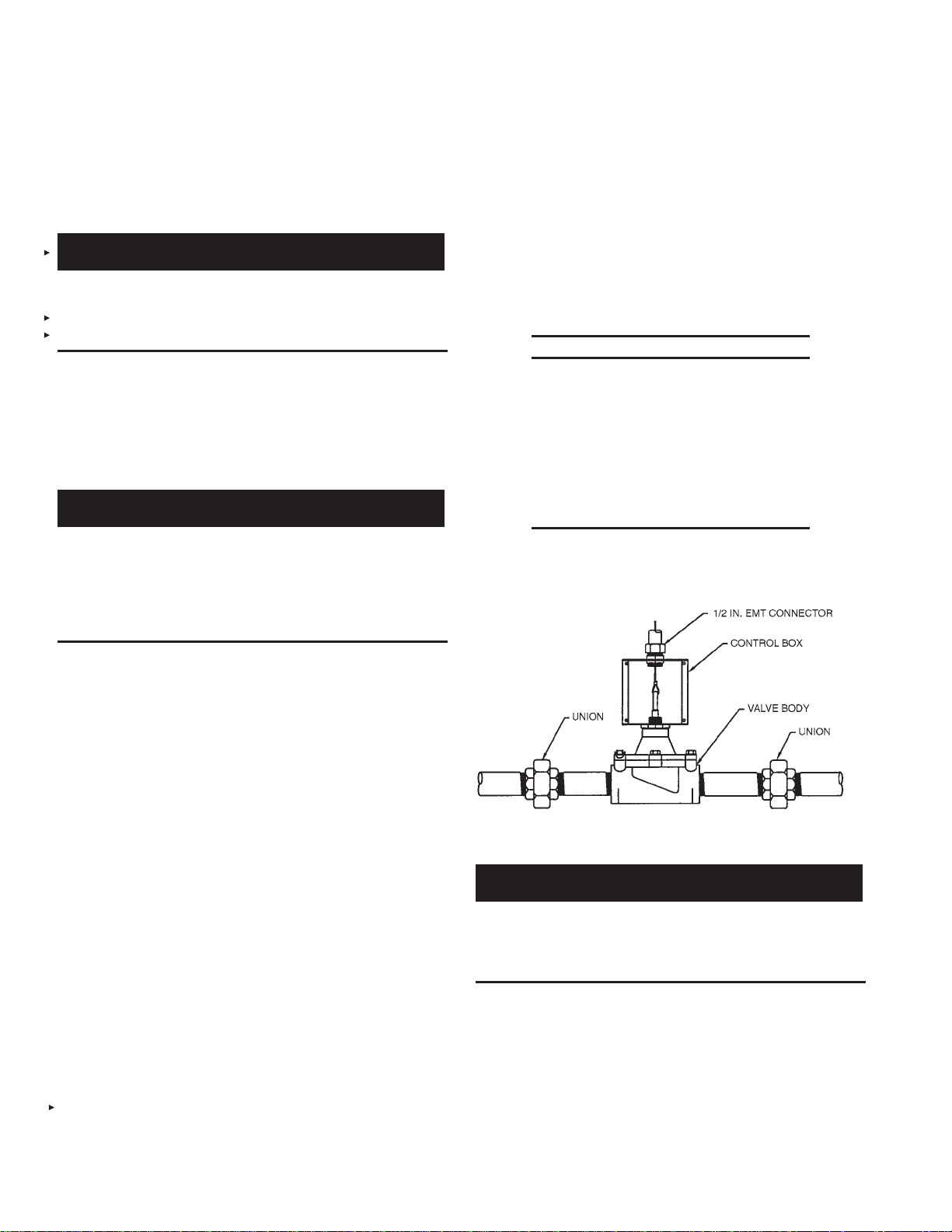
SECTION 4 – SYSTEM INSTALLATION
UL EX3830 ULC EX3830
PagE 4-10 REV. 06 2014-NOV-10
KITCHEN KNIGHT II Restaurant Fire Suppression Manual
GAS SHUT-OFF VALVE INSTALLATION
all gas valves are designed for indoor installation only. all gas
valve installation and testing shall be made in accordance with
the authority having jurisdiction.
WARNING
!
To reduce the risk of explosion due to leaking gas, make
certain that the gas line is turned off before connecting the gas
valve. Failure to comply could result in serious personal injury
or death.
Mechanical Gas Shut-Off Valve Installation
TEMPERATURE LIMITATIONS: Maximum ambient and fluid
temperature is 120 °F (49 °C).
POSITIONING: Valve may be mounted in any position.
PIPING:
CAUTION
To prevent damage to valve, DO NOT OVER-TIgHTEN PIPE
CONNECTIONS. Connect piping to valve in accordance with
markings on valve body. Pipe compound should be applied to
male pipe threads only. When tightening pipe, do not use valve
as a lever. To avoid strain on valve, assure all piping is aligned
and supported properly.
Gas Valve Cable Run Limitations When Used with Model
MCH3, EN-MCU3, and NMCH3 Control Heads and CBP-1,
SBP-1, and WBP-1 Pulley Elbows
Maximum length of cable: 100 ft (30.4 m)
Maximum # of pulleys: 30
Remove the gas valve cover and thread the stainless steel cable
through the conduit back to the control head. Thread the cable
through the hole in the gas valve ratchet wheel. The line must
then be crimped, and the crimp positioned inside the center of
the ratchet wheel.
NOTICE
Crimps must always be used in conjunction with two cable lengths. Loops are the
accepted method of connecting the cable
to mechanical components. The crimp must
never be used on a single cable. Exception:
Single cable crimp allowed in detection and
gas valve ratchet wheel using Stop Sleeve
(Part No. 26317) (Packages of 10: Part No.
24919).
at the gas valve, loop the cable through the valve stem and
secure it with the crimp provided (see Figure 4-19).
STRAINER INSTALLATION: For the protection of the gas
valve, install a strainer or suitable filter in the inlet piping, as
close to the gas valve as possible. Periodic cleaning of strainers
recommended.
PREVENTIVE MAINTENANCE:
1. Keep medium flowing through valve as free from foreign
material as possible.
2. Keep valve filter/strainer clean.
IMPROPER OPERATION:
1. Incorrect Pressure: Pressure to valve must be within range
specified on nameplate.
2. Leakage: If leakage is detected, contact an authorized
PYRO-CHEM distributor immediately.
The Model MCH3/NMCH3 Control Head is used to operate the
mechanical gas shut-off valve. This valve is located in the fuel
gas supply line to the cooking appliance(s). The valve body
has an arrow which indicates direction of gas flow through the
valve. The gas shut-off valve is spring loaded and requires five
pounds of force to hold it open. This force is supplied by a 1/16
in. (1.6 mm) diameter stainless steel cable that is connected to
the control head.
after the valve is installed in the gas line, 1/2 in. conduit must
be run from the top center knockout of the gas valve box to the
middle right-hand knockout in the control head. a PYRO-CHEM
KITCHEN KNIgHT II corner pulley is used wherever a change
in conduit direction is required.
FIGURE 4-19
002886PC
CAUTION
Do not over-tension wire rope going from control head to gas
valve at gas valve ratchet wheel. Over-tensioning may cause
the valve to not close properly, resulting in the fuel supply not
completely shutting off.
Page 61
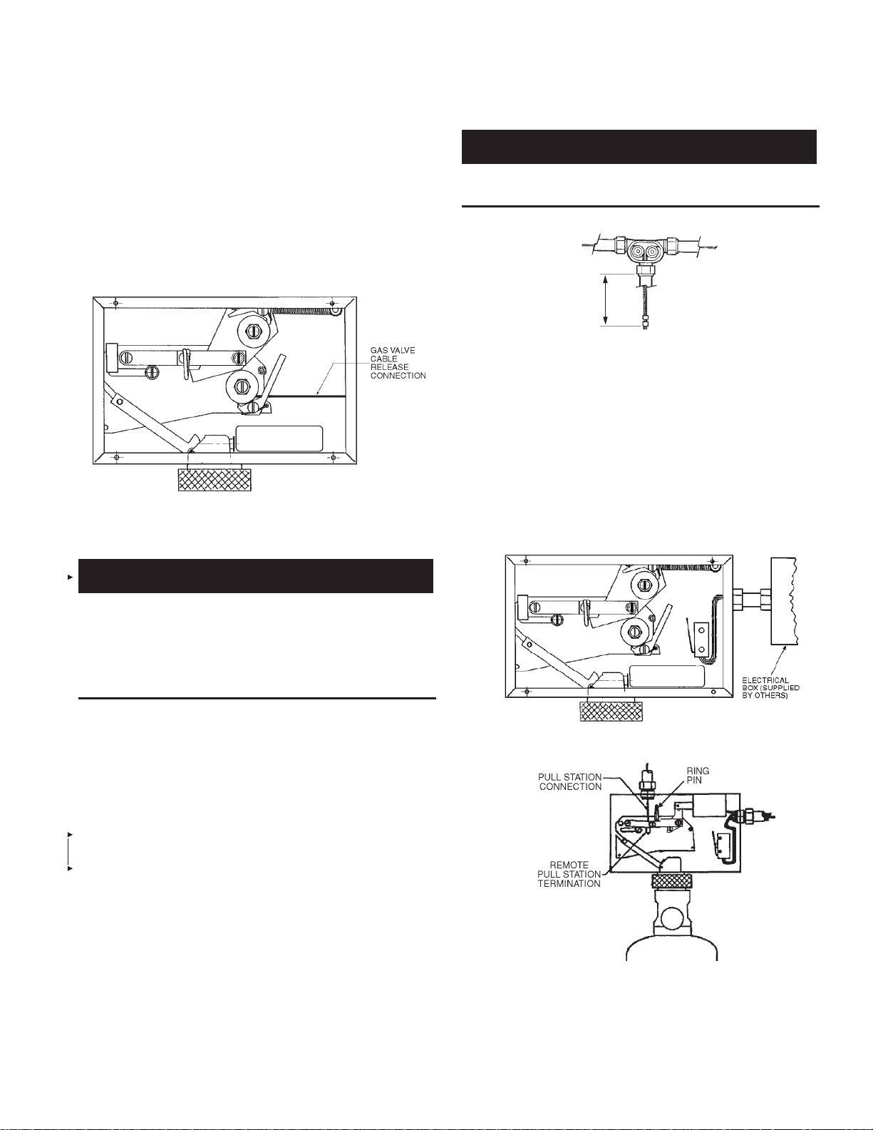
KITCHEN KNIGHT II Restaurant Fire Suppression Manual
GAS SHUT-OFF VALVE INSTALLATION (Continued)
The gas valve line can now be put into a set position by applying
tension to the gas valve line. This is accomplished by using a
1/2 in. hex wrench on the gas valve ratchet wheel. The ratchet
wheel will be ratcheted in a clockwise direction until the gas
valve is fully open. See Instruction Sheet (Part No. 550571)
included in gas valve shipping assembly, for detailed information. Secure the gas valve cover plate to the gas valve box with
the four screws provided. The gas valve line is now in a set
position. See Figure 4-20.
SECTION 4 – SYSTEM INSTALLATION
UL EX3830 ULC EX3830
2014-NOV-10 REV. 06 PagE 4-11
CAUTION
The pulley tee must never be used to connect multiple fusible
link lines to a single control head.
12 IN. (305 mm)
MINIMUM FROM
CRIMP SLEEVE TO
PULLEY TEE
FIGURE 4-20
006217PC
Electrical Gas Shut-off Valve Installation
WARNING
!
Before working on any electrical wiring, make certain main
power has been disconnected. Failure to disconnect main
power could cause personal injury or death if contact is made
with energized wires. all electrical wiring and connections to be
made in accordance with the authority having jurisdiction and
all local electrical codes.
The Model MCH3/ECH3/NMCH3 Control Head is used to
operate the electrical gas shut-off valve. This valve is located in
the fuel gas supply line to the cooking appliance(s). The valve
body has an arrow which indicates direction of gas flow through
the valve. a reset relay (Solenoid Monitor, Model SM-120) must
always be used with an electrical gas shut-off valve. For proper
wiring of the electrical gas shut-off valve, see Figure 4-16.
Note: Valve must be installed so that the solenoid is above the
horizontal pipe line with no more than a 5 degree lean either
way.
FIGURE 4-21
001091
ELECTRICAL (SNAP-ACTION) SWITCH INSTALLATION
See NFPa 72, “National Fire alarm Code,” Initiating Devices
section, for the correct method of wiring connection to the fire
alarm panel.
The Model MS-SPDT, MS-DPDT, MS-3PDT, or MS-4PDT
Electrical (Snap-action) Switch is available for use where
an electrical output is required. These switches can be field
installed in the control head. See Figure 4-22 and Figure 4-23
and refer to Instruction Sheet (Part No. 551159) included with
switch shipping assembly, for detailed mounting instructions.
FIGURE 4-22
006218PC
PULLEY TEE INSTALLATION
The Pulley Tee is used to connect two mechanical gas valves
or two remote mechanical pull stations to a single control head.
The cable proceeding from the control head must always enter
the branch of the pulley tee. See Figure 4-21.
a pulley tee that is used to close two gas valves can only be
used to close gas valves with similar stem travel. gas valves
from 3/4 in. up to 1 1/2 in. can be used on the same pulley tee.
a 2 in. gas valve can be used only with another 2 in. gas valve.
gas valves from 2 1/2 in. up to 3 in. can be used on the same
pulley tee. as an example, using a 3/4 in. gas valve with a 3 in.
gas valve will not allow the 3 in. valve to fully open.
FIGURE 4-23
003647PC
Page 62
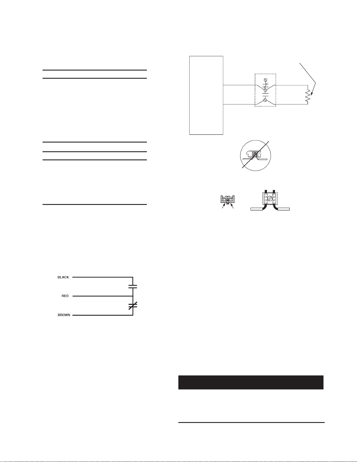
SECTION 4 – SYSTEM INSTALLATION
UL EX3830 ULC EX3830
PagE 4-12 REV. 06 2014-NOV-10
KITCHEN KNIGHT II Restaurant Fire Suppression Manual
ELECTRICAL (SNAP-ACTION) SWITCH INSTALLATION
(Continued)
NOTICE
The Model ECH3 Control Head is supplied
with a Model MS-DPDT Electrical (Snapaction) Switch. The DPDT switch is a
double switch with two sets of normally
open (N.O.) and normally closed (N.C.)
contacts. One set of contacts on the
switch must be used in the actuation/
detection circuit and cannot be used for electrical output.
NOTICE
No electrical connections shall be made
inside the control head. all electrical wiring
shall exit the control head through the
knock-out on the side of the box. all electrical connections must be made in an
approved electrical box.
These switches may be used to provide an electrical signal to
the main breaker and/or operate electrical accessories pro vided
the rating of the switch is not exceeded. Wiring con nections are
shown in Figure 4-24. The contact ratings for the switch are as
follows:
Contact Ratings For Electrical (Snap-Action) Switches
21 amps 1 HP, 125, 250, 277 VaC
or 2 HP, 250, 277 VaC
FIGURE 4-24
The alarm Initiating Switch (Part No. 550077) must be used to
close a supervised circuit to the building main fire alarm panel
when the control head actuates. This will signal the fire alarm
panel that there was a system actuation in the kitchen area.
This switch can be field installed in the control head. Refer to
Instruction Sheet (Part No. 550081) included with the switch
shipping assembly, for detailed mounting instructions. Wiring
connections are shown in Figure 4-25. The switch is rated at
50ma, 28VDC.
002903PC
FIRE aLaRM CONTROL PaNEL END-
FIRE aLaRM
CONTROL PaNEL
INITIaTINg
CIRCUIT
ININOUT
CORRECT – SEPaRaTE INCOMINg aND OUTgOINg CONDUCTORS
OF-LINE RESISTOR (BY OTHERS)
aLaRM INITIaTINg
SWITCH
OUT
FIGURE 4-25
004891/004905
PIPE AND NOZZLE INSTALLATION
all pipe ends shall be thoroughly reamed after cutting and all oil
and foreign matter removed from the pipe. The following procedures must be followed:
1. Use Schedule 40 black iron, chrome-plated, or stainless
steel pipe and fittings. Do not use hot-dipped galvanized
iron pipe or fittings in the agent distribution piping.
2. Before assembling the pipe and fittings, make certain all
ends are carefully reamed and blown clear of chips and
scale. Inside of pipe and fittings must be free of oil and dirt.
3. The distribution piping and fitting connections, located in the
hood or the protected area, must be sealed with pipe tape.
When applying pipe tape, start at the second male thread
and wrap the tape (two turns maximum) clockwise around
the threads, away from the pipe opening.
4. Do not over-tighten, but be sure the pipe is snug. Do not
back-off sections of pipe to make them fit better. If the pipe
was cut too short, re-cut another pipe to the proper length.
CAUTION
Do not apply Teflon tape to cover or overlap the pipe opening,
as the pipe and nozzles could become blocked and prevent
the proper flow of agent.
Do not use thread sealant or pipe joint compound.
Page 63

KITCHEN KNIGHT II Restaurant Fire Suppression Manual
SECTION 4 – SYSTEM INSTALLATION
UL EX3830 ULC EX3830
2014-NOV-10 REV. 06 PagE 4-13
PIPE AND NOZZLE INSTALLATION (Continued)
all piping shall be securely fastened by means of pipe hangers
and/or pipe straps. The spacing requirements for hangers/straps
depend on the pipe size being utilized. Refer to the Spacing
Guidelines Chart below.
Pipe Hanger Spacing Guidelines
Distribution Maximum Spacing Distance
Pipe Size Hanger to Hanger
in. ft (m)
1/4 4 (1.2)
3/8 5 (1.5)
1/2 6 (1.8)
3/4 8 (2.4)
a union should be installed in the discharge piping, as close
to the cylinder valve as possible, to permit disconnection and
removal for inspection and service. Dry air or nitrogen should be
blown through the discharge piping to remove chips and other
debris prior to installation of nozzles.
Nozzles shall be installed in accordance with the limitations
described in Section 3 – System Design. Blow-off caps are
provided for each nozzle. These will prevent dirt and grease
from clogging the nozzle.
INSTALLATION INSTRUCTIONS FOR CASTERED/
MOVEABLE EQUIPMENT USING PYRO-CHEM AGENT
DISTRIBUTION HOSE
CAUTION
The following instructions must be followed in their entirety.
Failure to do so may result in the KITCHEN KNIgHT II Fire
Suppression System not functioning properly due to incorrect
installation.
Critical Installation Requirements
1. Design and installation must be performed by qualified
personnel.
2. The agent Distribution Hose shall not be concealed within
or run through any wall, floor, or partition, and shall not have
any direct exposure to excessive heat or radiant flame from
the cooking appliances.
3. Strong cleaning solutions or chemical substances must not
come in contact with the agent Distribution Hose. These
may include acids, solvents, fluxes with zinc chloride, or
other chlorinated chemicals. In case of contact, rinse down
the agent Distribution Hose with water and dry thoroughly.
4. Contact with foreign objects, sharp edges, wiring, or
substances must be avoided.
5. Bending and flexing of agent Distribution Hose on moveable appliances (e.g. those factory equipped with casters)
should be limited to pulling and pushing the appliances in
or out for cleaning or maintenance. The hose shall never
be installed or bent tighter than a 3 in. (77 mm) radius (6 in.
(152 mm) dia meter) loop.
6. The agent Distribution Hose must not be kinked, twisted,
or have sharp bends when installed or when equipment is
pulled away from the wall.
7. Make sure that all fittings are tightened properly.
8. adequate means must be provided to limit the movement
of castered appliances. a 36 in. (914 mm) long Restraining
Cable supplied with the agent distribution hose is required
to be used for all castered appliances using the agent
Distribution Hose. (Refer to Restraining Cable Installation
Instructions.)
9. The Restraining Cable requires periodic maintenance to
ensure proper operation.
10. The Restraining Cable must be attached to the wall and
appliance anytime the distribution hose is connected to the
appliance.
11. Do not over-extend the agent Distribution Hose when
moving equipment (for cleaning, maintenance, etc.).
AGENT DISTRIBUTION HOSE INSTALLATION
INSTRUCTIONS
Before proceeding, CAREFULLY read all instructions, including
all CRITICAL INSTALLATION REQUIREMENTS.
General Requirements
1. The agent Distribution Hose (Part No. 434462) (which is
part of Discharge Hose and Tether Kit (Part No. 435982)),
is 1/2 in. (12.7 mm) diameter x 60 in. (1524 mm) long and is
provided with two male NPT swivels for ease of installation.
2. Maximum of six agent Distribution Hoses can be used
in each agent distribution piping network on PCL-460
and PCL-600 systems and a maximum of three agent
Distribution Hoses can be used in each agent distribution
piping network on PCL-160 and PCL-300 systems.
3. agent Distribution Hose can only be used for castered appliances or appliances setting on castered supports.
Installation Requirements
1. agent Distribution Hose must be connected to 3/8 in. NPT
black iron, chrome-plated, or stainless steel fittings. The
connection from hose to fitting requires a 1/2 in. x 3/8 in.
reducing coupling. all agent Distribution Hose connections
must be sealed with pipe tape. When applying pipe tape,
start at the second male thread on the swivel ends of the
hose. Wrap the tape (two turns maximum) clockwise around
the threads, away from the hose end fitting opening.
2. all connections of distribution piping to agent Distribution
Hose for castered appliances, with distribution nozzles
installed/affixed to the appliance, must be located behind
the cooking equipment in an area protected from obstructions and possible wear or damage.
3. 3/8 in. schedule 40 pipe will need to be run from the hose
connection to the distribution nozzle(s) installed/affixed
to the appliance. Pipe must be installed and adequately
secured at a height at or below the cooking surface of the
appliance. See Figure 4-31.
Page 64
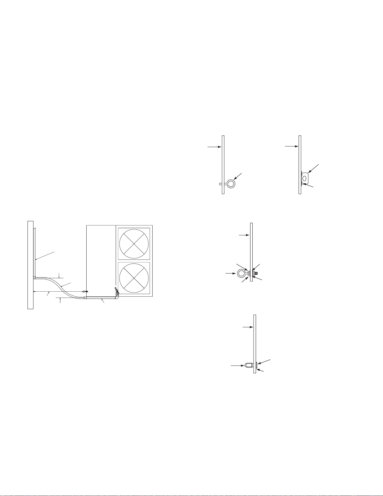
SECTION 4 – SYSTEM INSTALLATION
UL EX3830 ULC EX3830
PagE 4-14 REV. 06 2014-NOV-10
KITCHEN KNIGHT II Restaurant Fire Suppression Manual
Installation Requirements (Continued)
4. all existing distribution pipe and fitting limitations must be
observed and followed. Each flex distribution hose used is
to be considered as 300 ml when calculating the milliliters
per system.
5. all hose-to-pipe connection fittings are to be oriented in a
vertical down position.
6. The hose connections must be positioned below an elevation where the hose could be exposed to the radiant or
convected heat generated by normal cooking operations
(such as the horizontal plane of appliance’s cooking
surface), or to heat from appliance exhaust. as a minimum
height, the hose connection shall be no lower than 30 in.
(762 mm) from the floor. The distribution piping shall be
supported and secured per local plumbing practices.
7. Hose ends are to be offset 6-8 in. (152-203 mm) center
to center of fittings (see Figure 4-26) to maximize hose
life expectancy and facilitate appliance movement. With
the appliance in its normal operating position, check the
hose bend to make certain the bend is not less than a 3 in.
(76 mm) bend radius (6 in. (152 mm) diameter).
OVERHEAD VIEW
FLEX
HOSE
aPPLIaNCE
W
a
L
L
PIPE (NOT
SUPPLIED
IN KIT)
Restraining Cable Installation
Important: a Restraining Cable shall always be permanently
attached to the appliance and wall directly behind the appliance
when the agent Distribution Hose is installed. Removal of this
cable shall only occur when the agent Distribution Hose is not
installed to the appliance.
See Figure 4-27 for mounting the Restraining Cable to the wall.
See Figure 4-28 for mounting the Restraining Cable to the back
of an appliance.
RESTRAINING CABLE – WALL-MOUNTED OPTION
SHEET METaL
WaLL
STUD
RESTRAINING CABLE – APPLIANCE-MOUNTED OPTION
BaCK OF
aPPLIaNCE
NUT
EYE
BOLT
WaSHER
COVERED
WaLLS
SCREW
EYE BOLT
NYLON
LOCK NUT
WaSHER
WaLL
MOUNT
BRaCKET
(4) SELF TaPPINg
SHEET METaL
SCREWS
FIGURE 4-27
008088
TETHER
6-8 IN. (152-203 mm) OFFSET
CENTER TO CENTER
PIPE (SUPPLIED ONLY WITH HENNY PENNY
FRYER NOzzLE KIT (PaRT NO. 553389))
FIGURE 4-26
007828
RESTRAINING CABLE – HENNY PENNY-MOUNTED OPTION
BaCK OF
aPPLIaNCE
PHILIPS
SCREW
EYE
NUT
WaSHER
FIGURE 4-28
FIGURE 4-29
008089
008090
1. The Restraining Cable must be connected from the appliance to the wall or some other structurally sound object
capable of restraining the castered appliance from being
able to be pulled or pushed out to a point that will result in
strain or stress to the agent Distribution Hose.
2. The Restraining Cable should be installed in line with the
agent Distribution Hose.
Page 65
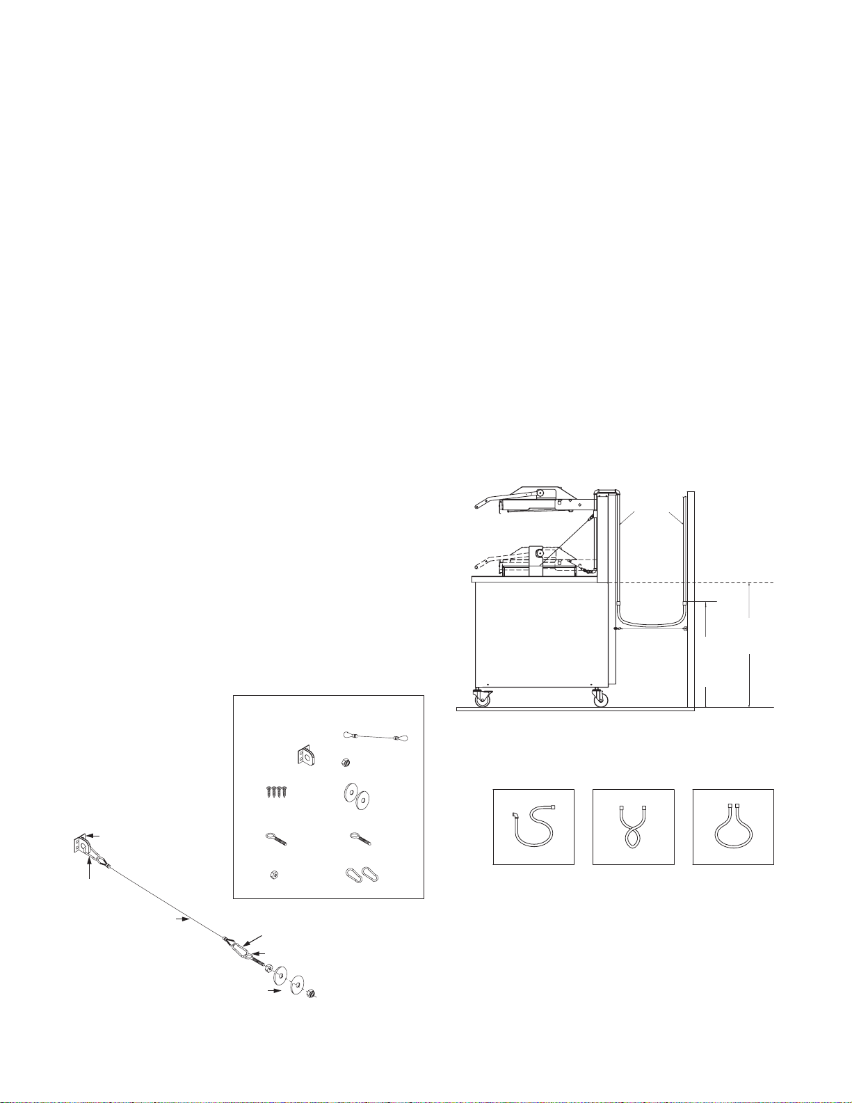
KITCHEN KNIGHT II Restaurant Fire Suppression Manual
SECTION 4 – SYSTEM INSTALLATION
UL EX3830 ULC EX3830
2014-NOV-10 REV. 06 PagE 4-15
Restraining Cable Installation (Continued)
3. For sheet metal covered walls, the Restraining Cable
assembly includes four 3/4 in. x #8 self tapping sheet
metal screws, and a Restraining Cable Bracket. Securely
attach the Restraining Cable Bracket to the sheet metal
covered wall using the 3/4 in. x #8 self tapping metal screws
provided.
4. For mounting to wall studs, the Restraining Cable assembly
includes one screw eye lag bolt, 5/16 in. x 2.5 in. (64 mm)
long.
5. Locate a structural area (frame) on the rear side of the
equipment that is in line with the wall attachment. Note: It
may be necessary to contact the appliance manufacturer for
a suitable location. Drill a 5/16 in. (7.9 mm) diameter hole.
Use caution when drilling hole, so that internal components
are not damaged.
6. The Restraining Cable assembly also includes a 5/16 in.
threaded eye-bolt, 5/16 in. hex head nut, 5/16 in nylon lock
nut, and two 5/16 in. flat washers. Thread the included hex
nut onto the eye-bolt. Slide one washer onto the eye-bolt
threads next to the nut. Then, slide the eye-bolt through
the drilled hole and place a washer and nylon locknut onto
the eye-bolt on the inside frame of the equipment. Tighten
securely.
7. attach one of the snap hooks (included in the Restraining
Cable package) on the end of the Restraining Cable to the
wall bracket and the other snap hook to the eye-bolt. See
Figure 4-30. after snap-hooking the assembly, seal the
Restraining Cable Loops to the wall bracketry and appliance
connection hardware with Lead Wire Seal (Part No. 197).
Note: For the Henny Penny Pressure Fryers that utilize
the PYRO-CHEM Henny Penny Fryer Nozzle Kit (Part No.
553389) the 5/16 in. philips screw supplied in the Henny
Penny Fryer Nozzle Kit, the 5/16 in. eye nut, and 5/16 in.
washer included in the Restraining Cable assembly Kit,
must be used. See Figure 4-29.
Final Installation Guidelines and Checkout Procedures
after the agent Distribution Hose and the Restraining Cable
is properly installed, carefully push the appliance back to its
normal operating position. Check that the hose does not have
sharp bends, and is not kinked, twisted, or caught on anything
behind the appliance.
1. Verify the Restraining Cable limits the travel of the appliance and prevents the application of any pull force or
bending stress on the agent Distribution Hose or hose-topipe connections.
2. Make certain there are no sharp bends and kinks in the
hose when pulling out the cooking equipment.
3. The agent Distribution Hose should always be in a vertical natural loop, never having any bends less than a 3 in.
(77 mm) radius (6 in. (152 mm) diameter), hose twists, or
sharp bends. See Figure 4-31. If any of these conditions
exist, the hose and/or hose connections will require installation modifications.
SIDE VIEW
ACCEPTABLE HOSE ORIENTaTION
agENT
DISTRIBUTION
3/8 IN
PIPINg
W
a
L
L
MIN.
30 IN.
(762
mm)
B – STaPLE BRaCKET
I – SNaP
HOOK
a – RESTRaININg
CaBLE
a – RESTRaININg CaBLE
B – STaPLE
BRaCKET
C – 3/4 IN. X #8
SCREWS (4)
D – EYE BOLT
E – 5/16 IN HEX NUT
EYE BOLT FaSTENINg
HaRDWaRE
RESTRAINING CABLE
INSTALLATION PACkAGE
I – SNaP HOOK
D – EYE BOLT
F – 5/16 IN NYLON
LOCK NUT
g – 5/16 IN
X 5/16 IN
WaSHERS
(2)
H – SCREW
EYE BOLT
I – SNaP
HOOK
FIGURE 4-30
007829
SHaRP BENDS TWISTINg FaTIgUE
UNACCEPTABLE HOSE ORIENTaTION
FIGURE 4-31
007830
4. Return the appliance to its normal operating position in
accordance with NFPa 96. Means shall be provided to
verify that the appliance returns to its original designed
positioning. Failure to do so may result in undue stress and
fatigue of the hose and hose connections.
Page 66

SECTION 4 – SYSTEM INSTALLATION
UL EX3830 ULC EX3830
PagE 4-16 REV. 06 2014-NOV-10
Agent Distribution Hose/Restraining Cable Six Month
Maintenance
1. Carefully pull or push out the appliance and verify that the
Restraining Cable limits the travel of the appliance and
prevents the application of any pull force or bending stress
on the agent Distribution Hose or hose-to-pipe connections.
2. Check the Restraining Cable to verify it is not frayed and is
securely fastened to the appliance and the wall or restraining location.
3. Check the hose and hose fittings and verify that the hose
remains in a vertical natural loop with no noticeable fatigue
at hose end couplings, no hose twists, no hose kinking or
sharp bends. See Figure 4-31.
4. Check the outer hose covering for signs of damage, checking, tears, or wear. If any of these signs are observed,
replace the hose.
5. Return the appliance to its normal operating position. again,
check the hose and hose fittings to verify that the hose does
not have sharp bends, and is not kinked, twisted, or caught
on anything behind the appliance. If any of these conditions
exist, the hose and/or hose connections will require installation modifications.
6. With the appliance in its normal operating position, check
the hose bend to make certain the bend is not less than a
3 in. (76 mm) bend radius (6 in. (152 mm) diameter). If less,
replace hose.
7. Verify that the appliance is returned to its original desired
location. Failure to do so may result in undue stress and
fatigue of the hose and hose connections.
8. 12-Year Maintenance – Hydrostatic test required at 220 psi
(15.2 bar) for hose assembly.
Note: agent Distribution Hose patent pending.
KITCHEN KNIGHT II Restaurant Fire Suppression Manual
Page 67

KITCHEN KNIGHT II Restaurant Fire Suppression Manual
SECTION 4 – SYSTEM INSTALLATION
UL EX3830 ULC EX3830
2014-NOV-10 REV. 06 PagE 4-17
(Page Intentionally Left Blank)
Page 68

SECTION 4 – SYSTEM INSTALLATION
UL EX3830 ULC EX3830
PagE 4-18 REV. 06 2014-NOV-10
KITCHEN KNIGHT II Restaurant Fire Suppression Manual
SYSTEM CHECkOUT AFTER INSTALLATION
1. Model MCH3/NMCH3 Mechanical Control Head
Before putting the system into service, all components must be
checked for proper operation. During this checkout, assure that
the carbon dioxide pilot cartridge is not installed in the control
head actuator. Remove the pull pin from the hole in the slide
plate.
To check satisfactory operation of the control head, cut the
terminal link or the “S” hook holding the link. This will relieve
all tension on the fusible link line and operate the control head.
The slide plate will move fully to the right. The gas valve cable
will be released, causing the gas valve to close. any auxiliary
equipment connected to the dry contacts of the solenoid monitor
and/or the electrical (snap-action) switch in the control head will
operate.
If any of these events fail to occur, the problem must be investigated and repaired.
Repair the terminal link and put the fusible link line back into the
set position. This is accomplished by using a 1/2 in. hex wrench
on the fusible link line ratchet wheel. The ratchet wheel will be
ratcheted in a clockwise direction until the spring plate makes
contact with the top of the control head box.
Note: Tension must be set on fusible link detection line before
control head can be set.
Once the fusible link line is set (refer to Pages 4-4 through
4-6 for fusible link installation details), the control head can be
placed in the set position. To set the control head, the slide
plate is moved from right to left, ensuring the bolt extending from
the cam arm is in the slot provided in the slide plate. Continue
moving the slide plate to the left until the latching arm is in the
locked position.
Once the control head is set, pull the pull handle on the remote
pull station to assure that the control head operates. If the
control head operates normally, the control head can be reset
as described above. Insert the pull pin into the hole in the slide
plate above the latching arm. Replace the pull station handle,
pull pin, and nylon tie.
Ensure that the gas valve is fully open by ratcheting the gas
valve ratchet wheel.
CAUTION
Before screwing the 16 gram carbon dioxide pilot cartridge into
the actuator, ensure that the actuator has an o-ring washer
installed.
Using a felt-tipped marker, write the date of installation on
the carbon dioxide pilot cartridge. Screw the cartridge into the
control head actuator until hand-tight. Never use a wrench to
tighten the cartridge into the actuator.
Remove the pull pin from the hole in the slide plate and install
the control head cover. Insert the pull pin through the local
manual control handle and into the bushing. Secure the pull pin
with the nylon tie provided.
2. Model ECH3-24/120 Electrical Control Head
Before putting the system into service, all components must be
checked for proper operation. During this checkout, ensure that
the CO2 pilot cartridge is not installed in the control head actuator. Remove the pull pin from the hole in the slide plate.
CAUTION
Make certain to remove the CO2 cartridge. Failure to do so
during testing will result in system actuation.
Testing Thermal Detectors
1. Remove the electric control head cover.
2. Test each detector individually and reset control panel and
recock release mechanism after each test. (Refer to proper
aUTOPULSE control panel reset instructions).
3. Using a heat gun positioned approximately 12 in. (305 mm)
from the detector, apply heat to the detector for about one
minute. Overheating will cause damage to the detector.
applying heat to the detector will cause the control head to
operate or will cause the aUTOPULSE control panel to go
into an alarm condition, and activate the control head. When
the control head operates, the following will take place: a)
The slide plate will move fully to the right; b) The indicator
light on the solenoid monitor will go out; and c) any auxiliary
equipment connected to the dry contacts of the solenoid
monitor and/or the snap-action switch in the control head
will operate. If any of these events fail to occur, the problem
must be investigated and repaired.
4. after all the thermal detectors have cooled, the aUTOPULSE
control panel can be reset (refer to proper aUTOPULSE
control panel reset instructions) and the control head can
be placed in the set position. To set the control head, the
slide plate must be moved from right to left, ensuring the
bolt extending from the cam arm is in the slot provided in the
slide plate. Continue moving the slide plate to the left until
the latching arm is in the locked position.
Testing Remote Pull Station
1. Once the control head is set, pull the pull handle on the
remote pull station to assure that the control head operates.
If the control head operates normally, the control head can
be reset as described in Step 4 in the “Testing Thermal
Detectors” section on this page.
2. Insert the pull pin into the hole in the slide plate above the
latching arm.
3. Replace the pull station handle, pull pin, and break rod.
Page 69
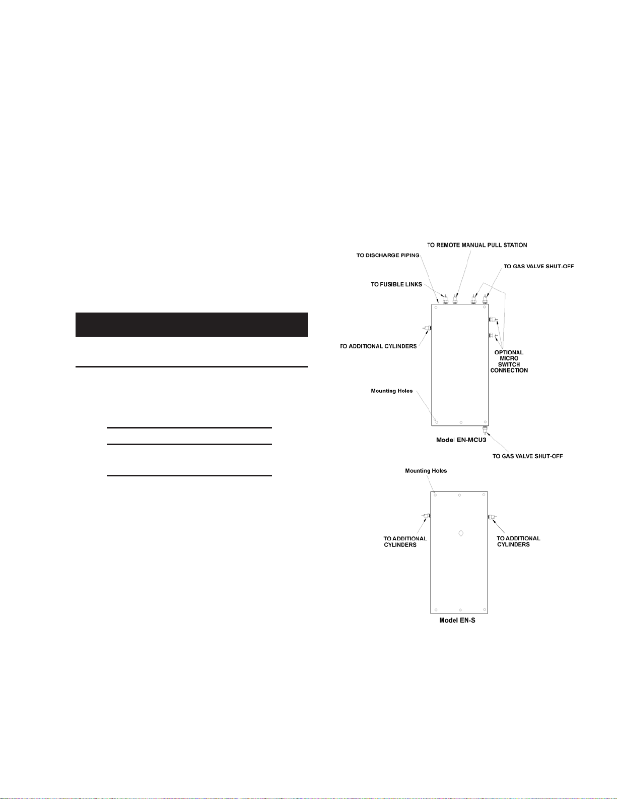
KITCHEN KNIGHT II Restaurant Fire Suppression Manual
SECTION 4 – SYSTEM INSTALLATION
UL EX3830 ULC EX3830
2014-NOV-10 REV. 06 PagE 4-19
SYSTEM CHECkOUT AFTER INSTALLATION (Continued)
Completing System Checkout
1. Make certain the aUTOPULSE control panel is reset and
the control head is re-cocked and set. If the Model SM-120
Solenoid Monitor is used instead of an aUTOPULSE control
panel, energize the actuation/detection circuit by depressing the push button on the solenoid monitor.
2. Using a felt-tipped marker, write the date of installation on
the CO2 pilot cartridge. Ensure that the actuator has an
o-ring installed, and screw the cartridge into the control
head actuator until hand tight. Continue installation of
cartridge by turning an additional 1/4 turn using a wrench or
pliers. Use caution not to damage cartridge.
Note 1: Four to five threads should be showing when the
cartridge in engaged properly. It is important that no more
than five threads be showing.
Note 2: The cartridge and o-ring shall be replaced annually.
CAUTION
Do not over-tighten cartridge. Over-tightening can result in
premature puncturing of the cartridge seal.
3. Remove the pull pin from the hole in the slide plate and
install the control head cover. Insert the pull pin through the
local manual control handle and into the bushing. Secure
the pull pin with the tie provided.
ENCLOSURE INSTALLATION INSTRUCTIONS –
MODEL EN-MCU3 AND MODEL EN-S
Enclosure Mounting
The Model EN-MCU3 and/or EN-S Enclosure must be securely
anchored to the wall using bolts or lag screws. The wall to which
the enclosure is attached must be sufficiently strong. The enclosure should never be fastened to drywall or similar material. If
this type of wall is encountered, studs must be located and the
enclosure fastened to them.
Three center mounting holes allow either enclosure to be
mounted on a single stud. Four corner mounting holes are also
available. See Figure 4-32.
NOTICE
Refer to NFPa-17a for additional inspection requirements.
FIGURE 4-32
002946PC
Page 70
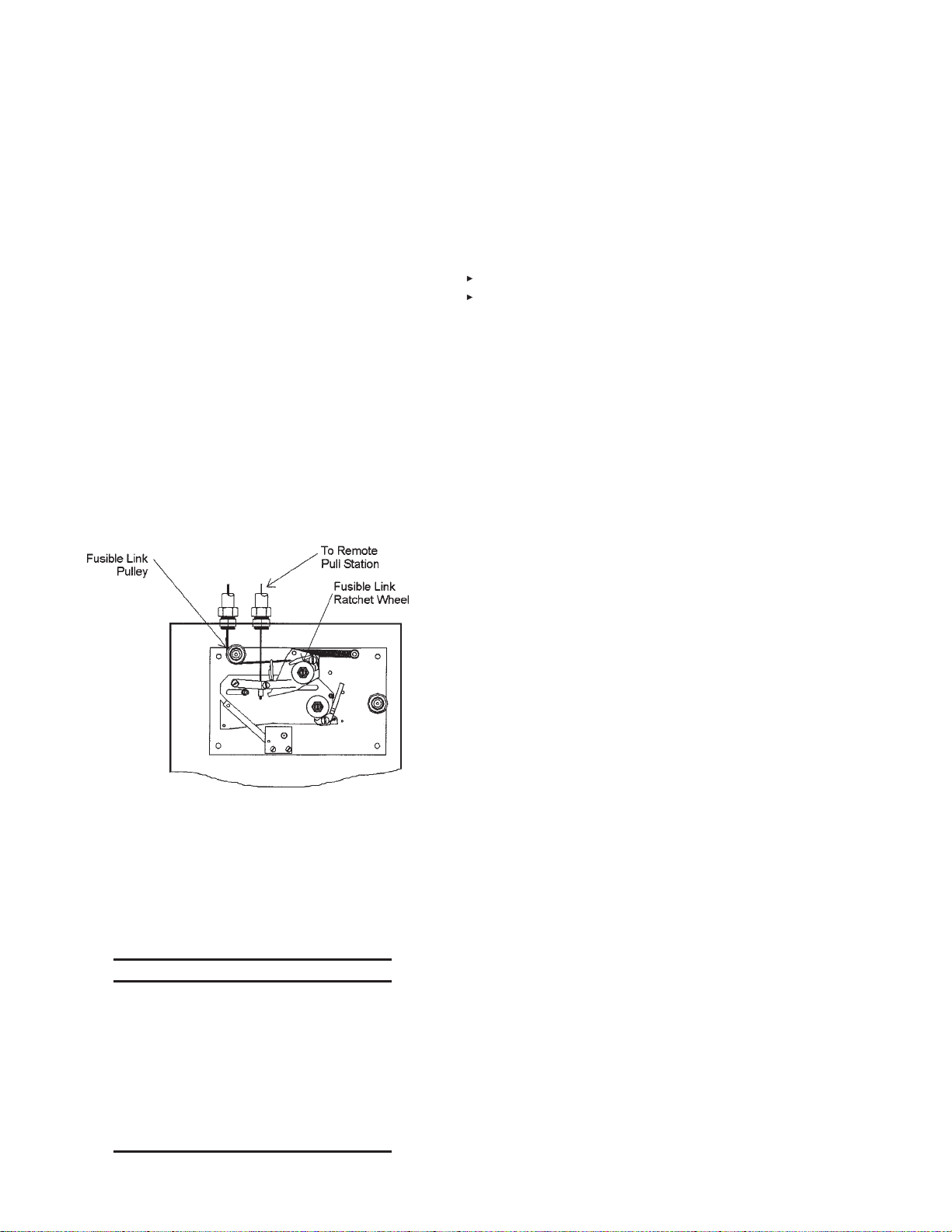
SECTION 4 – SYSTEM INSTALLATION
UL EX3830 ULC EX3830
PagE 4-20 REV. 06 2014-NOV-10
Fusible Link Detector Installation
The Model EN-MCU3 Enclosure can support a fusible link
detection system. The Model EN-S Enclosure cannot support
a fusible link detection system and must be used in conjunction
with the Model EN-MCU3 Enclosure or a Model MCH3/ECH3/
NMCH3 Control Head.
after mounting the enclosure, the fusible link line can be
installed. The first step to installing the fusible link line is to install
the detector brackets. These brackets must be installed in the
plenum area of the ventilation hood over all protected appliances
and in each duct. See Section 3 – System Design for detector
placement guidelines. Connect the fusible link brackets together
using 1/2 in. EMT conduit and the conduit connectors supplied
in the detector kit (Model FLK-1/1a). PYRO-CHEM KITCHEN
KNIgHT II corner pulleys must be used whenever a change in
conduit direction is necessary. The conduit is connected to the
enclosure through a top knockout.
See “Fusible Link Detector Installation” section (Pages 4-4 –
4-7) for fusible link installation guidelines. Before attaching the
stainless steel cable to the fusible link line ratchet wheel, it must
be run below the fusible link line pulley in the enclosure. See
Figure 4-33.
KITCHEN KNIGHT II Restaurant Fire Suppression Manual
The fusible link line can now be put into a set position by
tensioning the fusible link line. This is accomplished by using
a 1/2 in. hex wrench on the fusible link line ratchet wheel. The
ratchet wheel will be ratcheted in a clockwise direction until the
spring plate is parallel to the top of the enclosure. The fusible
link line is now in a set position.
Note: Tension must be set on fusible link detection line before
control head can be set.
Once the fusible link line is set, the Model EN-MCU3 Enclosure
can be placed in the set position. To set the Model EN-MCU3,
the slide plate is moved from right to left, ensuring the bolt
extending from the cam arm is in the slot provided in the slide
plate. Continue moving the slide plate to the left until the latching
arm is in the locked position. Insert the pull pin into the hole in
the slide plate above the latching arm. This will lock the control
mechanism in the set position, eliminating accidental actuation
during the rest of the installation procedure. See Figure 4-33.
Remote Pull Station Installation
The Model RPS-M Remote Mechanical Pull Station is used
for remote manual actuation of the Model EN-MCU3 It is to
be located near an exit in the path of egress from the hazard.
Height and location of pull station should be determined in
accordance with the authority Having Jurisdiction.
The Pull Station is connected to the Model EN-MCU3 using 1/16
in. (1.6 mm) diameter stainless steel cable. The cable enters the
Model EN-MCU3 through a knockout in the top of the enclosure.
See Figure 4-33.
See “Remote Pull Station Installation” section (Pages 4-8 – 4-9)
for remote pull station installation guidelines.
FIGURE 4-33
002947PC
Setting the Model EN-MCU3
after the last link in the series is connected, the cable should be
fed through the conduit back to the Model EN-MCU3. It must be
fed under the fusible link line pulley and through the hole in the
fusible link ratchet wheel. The line must then be crimped, and
the crimp positioned inside the ratchet wheel.
NOTICE
Crimps must always be used in conjunction with two cable lengths. Loops are the
accepted method of connecting the cable to
mechanical components. The crimp must
never be used on a single cable. Exception:
Single cable crimp allowed in detection and
gas valve ratchet wheel using Stop Sleeve
(Part No. 26317) (Packages of 10: Part No.
24919).
Gas Shut-off Valve Installation
The Model EN-MCU3 can be used to operate a mechanical
gas shut-off valve. This valve is located in the fuel gas supply
line to the cooking appliance(s). The valve body has an arrow
which indicates direction of gas flow through the valve. The gas
shut-off valve is spring loaded and requires five pounds of force
to hold it open. This force is supplied by a 1/16 in. diameter
(1.6 mm) stainless steel cable that is connected to the Model
EN-MCU3.
See “gas Shut-off Valve Installation” section (Page 4-11 – 4-12)
for gas valve shut-off installation guidelines.
after the valve is installed in the gas line, 1/2 in. conduit must be
run from the top center knockout of the gas valve box to the top
or bottom knockout in the enclosure. See Figure 4-32. a PYROCHEM KITCHEN KNIgHT II corner pulley is used wherever a
change in conduit direction is required.
Remove the gas valve cover and thread the stainless steel cable
through the conduit back to the Model EN-MCU3. If the cable
enters the enclosure through the bottom knockout, the cable
must be run over the gas valve line pulley (see Figure 4-34).
If the cable enters the enclosure through the top knockout, the
cable must be run under the gas valve line pulley (see Figure
4-35). Thread the cable through the hole in the gas valve ratchet
wheel. The line must then be crimped, and the crimp positioned
inside the center of the ratchet wheel.
Page 71
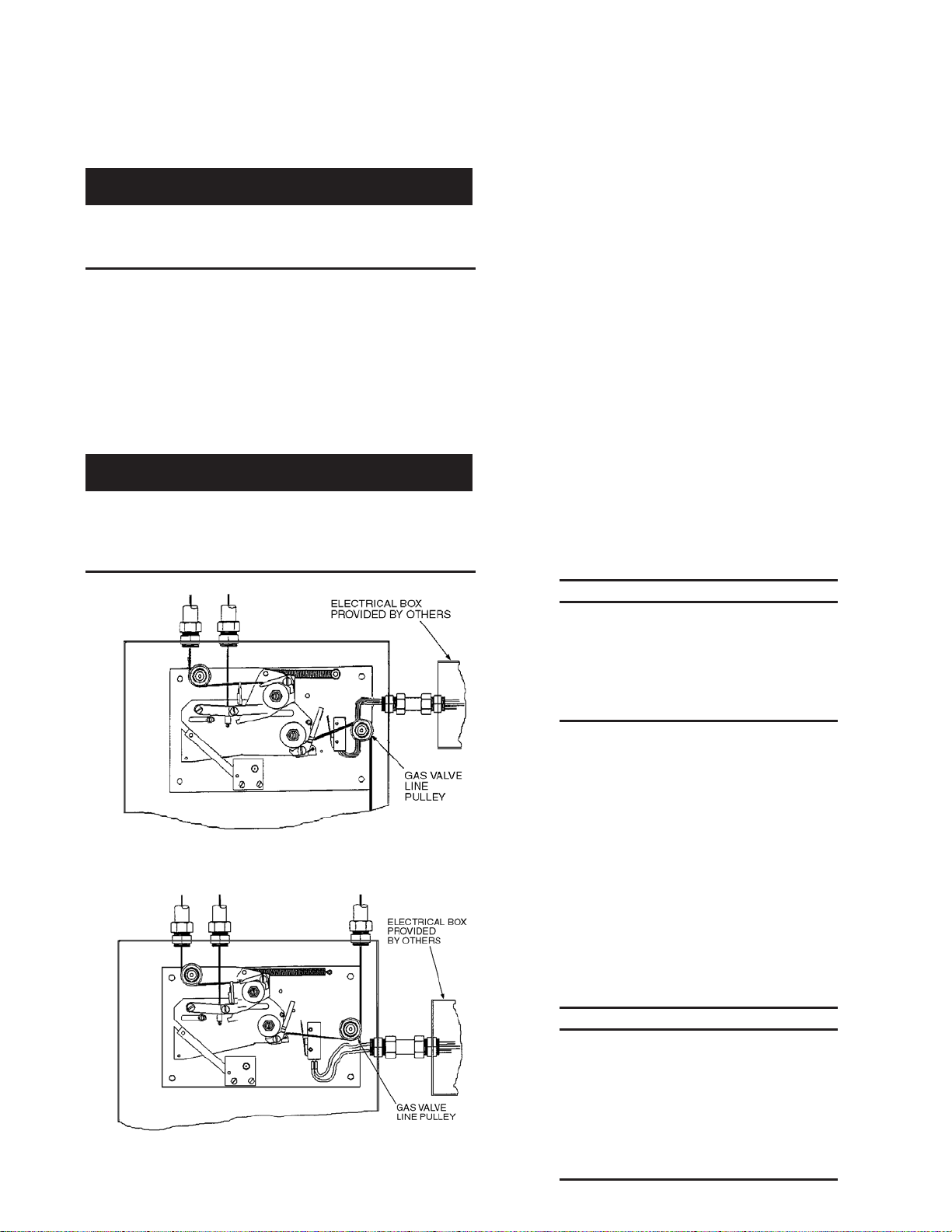
KITCHEN KNIGHT II Restaurant Fire Suppression Manual
SECTION 4 – SYSTEM INSTALLATION
UL EX3830 ULC EX3830
2014-NOV-10 REV. 06 PagE 4-21
Gas Shut-off Valve Installation (Continued)
CAUTION
The gas valve cable must always utilize the gas valve pulley
and exit the top or bottom of the enclosure. The gas valve
cable cannot exit the side of the enclosure.
at the gas valve, loop the cable through the valve stem and
secure it with the crimp provided (see Figure 4-19).
The gas valve line can now be put into a set position by applying
tension to the gas valve line. This is accomplished by using a
1/2 in. hex wrench on the gas valve ratchet wheel. The ratchet
wheel will be ratcheted in a clockwise direction until the gas
valve is fully open. Secure the gas valve cover plate to the gas
valve box with the four screws provided. The gas valve line is
now in a set position. See Figure 4-34 and/or Figure 4-35.
CAUTION
Do not over-tension wire rope going from control head to
gas valve at gas valve ratchet wheel. Over-tensioning may
cause the valve to not close properly, resulting in the fuel
supply not completely shutting off.
Electrical (Snap-Action) Switch Installation
See NFPa 72, “National Fire alarm Code,” Initiating Devices
section, for the correct method of wiring connection to the fire
alarm panel.
The Model MS-SPDT, MS-DPDT, MS-3PDT, or MS-4PDT Electri cal (Snap-action) Switch is available for use where an electrical output is required. These switches can be field installed in
the Model EN-MCU3. See Figure 4-34 and/or Figure 4-35.
These switches may be used to provide an electrical signal to
the main breaker and/or operate electrical accessories provided
the rating of the switch is not exceeded. Wiring connections for
the Model MS-SPDT are shown in Figure 4-24. The contact
ratings for both switches are as follows:
Contact Ratings For Electrical (Snap-Action) Switches:
21 amps
1 HP, 125, 250, 277 VaC or 2 HP, 250, 277 VaC
Three knockouts are provided for electrical (snap-action) switch
wiring. The upper right-side knockout must be used when the
gas valve line exits the bottom of the enclosure (see Figure
4-34). The lower right-side knockout must be used when the gas
valve line exits the top of the enclosure (see Figure 4-35). an
additional knockout located on the top of the enclosure is also
provided (see Figure 4-32) and may be used in either situation.
NOTICE
No electrical connections shall be made
inside the control head. all electrical wiring
shall exit the control head through the knockout on the side of the box. all electrical
connections must be made in an approved
electrical box.
Cylinder Installation
1. Single Cylinder Installation – PCL-300/460
The Model EN-MCU3 can be used for single cylinder installations. It can support either the Model PCL-300 or PCL-460
cylinder assemblies. The cylinder must be placed in the enclo-
FIGURE 4-34
002948PC
sure with the discharge port to the left. No additional mounting
bracket is required when the Model EN-MCU3 is used.
In order to actuate the agent cylinder from the Model EN-MCU3s
control mechanism, pneumatic tubing must be used to connect
the actuator to the valve cap assembly of the agent cylinder
valve. a 1/8 in. NPT x 1/4 in., 45° flare type elbow is included
and must be installed in the actuator of the Model EN-MCU3
Enclosure. See Figure 4-36.
NOTICE
Pneumatic tubing (copper) used for cylinder
actuation shall have an outside diameter of
1/4 in. (6.4 mm) with a minimum wall thickness of 1/32 in. (0.8 mm). This is commonly
known as refrigeration-type copper tubing. all
tubing fittings shall be of the 1/4 in., 45° flare
FIGURE 4-35
002949PC
type conforming to SaE J513c. Compression
type fittings are not acceptable.
Page 72
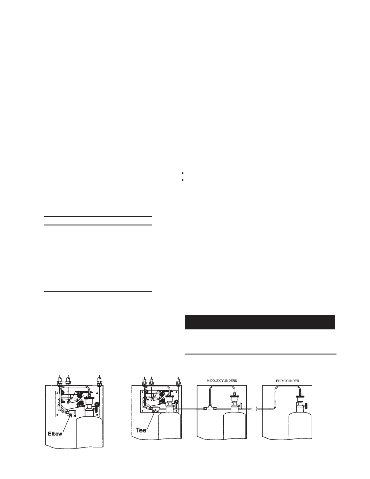
SECTION 4 – SYSTEM INSTALLATION
UL EX3830 ULC EX3830
PagE 4-22 REV. 06 2014-NOV-10
Cylinder Installation (Continued)
2. Multiple Cylinder Installation – PCL-300/460
The Model EN-S can be used in conjunction with the Model
EN-MCU3 Enclosure or Model MCH3/ECH3 Control Head for
multiple cylinder installations. a single Model EN-MCU3 can be
used to pneumatically actuate a maximum of five agent cylinders with the 16 gram CO2 cartridge. One agent cylinder can be
installed in the Model EN-MCU3 Enclosure; the additional agent
cylinder(s) can either be mounted in a Model EN-S Enclosure
or with a Model MB-15 Mounting Bracket. When an enclosure is
used, the cylinders must be placed in the enclosure(s) with the
discharge port to the left. No additional mounting bracket is
required when a cylinder is installed in the Model EN-MCU3
or EN-S Enclosure.
In order to actuate the agent cylinders from the Model EN-MCU3,
pneumatic tubing must be used to connect the EN-MCU3 actuator to the valve cap assembly of each agent cylinder valve.
Pneumatic tubing or stainless steel actuation hose must be run
from the actuator in the Model EN-MCU3 to the Model EN-S(s)
through the side knockouts. a 1/4 in., 45° flare x 1/4 in., 45° flare
x 1/8 in. NPT tee is included with the Model EN-S and must be
installed in the Model EN-MCU3 actuator. See Figure 4-37.
NOTICE
Pneumatic tubing (copper) used for remote
cylinder actuation shall have an outside diameter of 1/4 in. (6.4 mm) with a minimum
wall thickness of 1/32 in. (0.8 mm). This is
commonly known as refrigeration-type copper
tubing. all tubing fittings shall be of the 1/4
in., 45° flare type conforming to SaE J513c.
Compression type fittings are not acceptable.
a single Model EN-MCU3 can actuate up to four cylinders with
25 ft (7.6 m) of pneumatic tubing or stainless steel actuation
hose or a maximum of five cylinders with up to 18 ft (5.4 m) of
pneumatic tubing or stainless steel actuation hose.
KITCHEN KNIGHT II Restaurant Fire Suppression Manual
To check satisfactory operation of the control mechanism, cut
the terminal link or the “S” hook holding the link. This will relieve
all tension on the fusible link line and operate the control mechanism. The slide plate will move fully to the right. The gas valve
cable will be released, causing the gas valve to close. any auxiliary equipment con nect ed to the dry contacts of the solenoid
monitor and/or the electrical (snap-action) switch in the Model
EN-MCU3 will operate.
If any of these events fail to occur, the problem must be investigated and repaired.
Repair the terminal link and put the fusible link line back into the
set position. This is accomplished by using a 1/2 in. hex wrench
on the fusible link line ratchet wheel. The ratchet wheel will be
ratcheted in a clockwise direction until the spring plate is parallel
to the top of the enclosure.
Note: Tension must be set on fusible link detection line before
control head can be set.
Once the fusible link line is set, the control mechanism can be
placed in the set position. To set the control mechanism, the
slide plate is moved from right to left, ensuring the bolt extending from the cam arm is in the slot provided in the slide plate.
Continue moving the slide plate to the left until the latching arm
is in the locked position. Once the control mechanism is set,
pull the pull handle on the remote pull station to assure that
the control head operates. If the control mechanism operates
normally, the control mechanism can be reset as described
above. Insert the pull pin into the hole in the slide plate above
the latching arm. Replace the pull station handle, pull pin, and
nylon tie.
To test the thermal detectors, use a heat gun. Hold the gun
approximately 12 in. (305 mm) from the detector for about one
minute. Do not overheat. Overheating can cause damage to
detector. allow detector to cool after testing.
assure that the gas valve is fully open by ratcheting the gas
valve ratchet wheel. Do not overtighten.
CAUTION
System Checkout After Installation
Before putting the system into service, all components must be
checked for proper operation. During this checkout, ensure that
Before screwing the 16 gram carbon dioxide pilot cartridge into
the actuator, ensure that the actuator has an o-ring washer
installed.
the carbon dioxide pilot cartridge is not installed in the Model
EN-MCU3 actuator. Remove the pull pin from the hole in the
slide plate.
002950PC
FIGURE 4-36 FIGURE 4-37
Page 73

KITCHEN KNIGHT II Restaurant Fire Suppression Manual
SECTION 4 – SYSTEM INSTALLATION
UL EX3830 ULC EX3830
2014-NOV-10 REV. 06 PagE 4-23
System Checkout After Installation (Continued)
Using a felt-tipped marker, write the date of installation on the
carbon dioxide pilot cartridge. Screw the cartridge into the Model
EN-MCU3 actuator until hand-tight.
Install cartridge per the following:
a. It is recommended that the cartridges first be fully hand
tightened and then further tightened 1/4 to 3/4 turn using a
needle-nose Vise-grips. Note: Use caution not to damage
cartridge with Vise-Grips.
Note 1: Four to five threads should be showing when the
cartridge is engaged properly. It is important that no more than
five threads be showing.
Note 2: The cartridge and o-ring shall be replaced annually.
CAUTION
Do not over-tighten cartridge. Over-tightening can result in
premature puncturing of the cartridge seal.
Remove the pull pin from the hole in the slide plate. Secure the
Model EN-MCU3 or EN-S cover with the screws provided.
FLEXIBLE CONDUIT INSTALLATION
Flexible conduit allows for quicker installations and the convenience of being able to route the cable over, under, and around
obstacles.
Flexible conduit is designed for use with PYRO-CHEM® restaurant systems. Flexible conduit can be used as a substitute for
standard EMT conduit or can be used with EMT conduit.
NOTICE
Flexible conduit CANNOT be used in
detection systems. Flexible conduit is
intended for indoor use only.
• The maximum distance from a PYRO-CHEM control head to
a mechanical gas valve is 75 ft (22.8 m) with a maximum of
4-90° bends in the flexible conduit and four pulley elbows.
• Any portion of the flexible conduit system can be substituted
with EMT conduit provided the proper connections are used to
join the two types of conduit.
• All bends in the flexible conduit system must have a minimum
bend diameter of 6 in. (153 mm).
• When the flexible conduit is used to make 90° bends between
a control head and a mechanical gas valve, the bends must
start at the control head. No pulley elbows can be used
between the bends. If more than 360° of bends are needed,
then pulley elbows can be used.
• When the flexible conduit is used to make 90° bends between
a control head and a pull station, the bends must start at the
control head. No pulley elbows can be used between the
bends. If more than 360° of bends are needed, then pulley
elbows can be used.
• Only PYRO-CHEM pull stations utilizing a composite (black)
bushing on the back side of the pull station cover can be used
with flexible conduit.
• When not utilizing a Conduit Offset (Part No. 436063) 2-45°
bends in the flexible conduit are allowed between the strain
relief on top of the control head and the location where the
flexible conduit is supported. Note: This is allowed on pull
station installations only.
• When installing flexible conduit, conduit should be secured at
intervals not to exceed 5 ft (1.5 m) and before and after each
bend. Flexible conduit CaNNOT slide in the clamp(s) used for
mounting. Make certain mounting clamp(s) do not pinch the
flexible conduit. The following style clamp (‘P’ clip) (Part No.
436150) is a suitable type for use on flexible conduit.
Design Requirements
• Prior to starting the flexible conduit installation, the detection
system must be complete and attached to the control head.
• Flexible conduit cannot be utilized in detection systems.
• Flexible Conduit Inserts (Part No. 434347) can ONLY be used
with the flexible conduit system.
• The maximum distance from a PYRO-CHEM control head to
a mechanical pull station is 140 ft (42.6 m) with a maximum
of 360° (for example, 3-90° and 2-45° bends, 2-90° and 4-45°
bends, etc.) bends in the flexible conduit, one pulley tee (refer
to Design, Installation Manual for detailed splicing instructions), two splices, and 15 pulley tees. Note: When installing
flexible conduit, make sure to feed wire rope through conduit
directly from the spool of wire rope. DO NOT pre-cut wire rope.
Feeding pre-cut rope through flexible conduit will cause excessive kinks in the rope, making it difficult to install.
FIGURE 4-38
008141
TABLE 4-1
Manual Mechanical
Pull gas Valve Detection
90° Cable Bends 4 4 N/a
Bend Diameter – in. (mm) 6 (152) 6 (152) N/a
Mechanical Corner Pulley 15 4 N/a
Conduit Secured Max. ft (m) 5 (1.5) 5 (1.5) N/a
Conduit Max. Length ft (m) 140 (42.6) 75 (22.8) N/a
Conduit Offset or 2-45° 1 0 N/a
Bends (Only between the
strain relief fitting and
support location)
Pulley Tees 1 0 N/a
Splices 2 0 N/a
Page 74
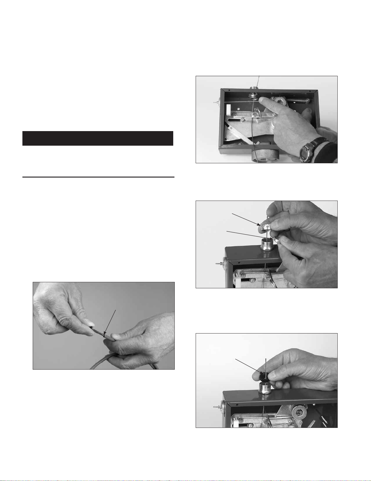
SECTION 4 – SYSTEM INSTALLATION
UL EX3830 ULC EX3830
PagE 4-24 REV. 06 2014-NOV-10
KITCHEN KNIGHT II Restaurant Fire Suppression Manual
FLEXIBLE CONDUIT INSTALLATION (Continued)
Installation Instructions
Note: Do not add any type of lubricants inside or on the flexible
conduit. Make certain stainless steel wire rope is clean and
debris-free.
The flexible conduit should be routed along the same path that
EMT conduit would normally be run. Stainless steel wire rope
should be routed through the flexible conduit as it is in EMT
conduit.
CAUTION
Flexible conduit must not be located within 6 in. (152 mm) of
the hood or in areas exceeding 130 °F (54 °C). also, do not
route flexible conduit in areas where conduit can be crushed,
pinched, or broken.
Flexible conduit can be used to connect a PYRO-CHEM control
head to a remote pull station or mechanical gas valves.
Before starting the system installation, take a few minutes to
plan the layout of the system. This will minimize the amount of
components needed to complete the installation. Once the path
of the flexible conduit has been determined, verify that the layout
does not exceed the design requirements.
Connecting the Flexible Conduit to the PYRO-CHEM
Control Head, Electrical Box, Pull Station, or Mechanical
Gas Valve
1. Layout the flexible conduit and secure it in place. Note: If
inner liner is crimped, turn a drywall screw into the end to
open it. See Figure 4-39.
2. Starting at the PYRO-CHEM control head, connect the
conduit connector using the supplied nut. Use only PYROCHEM Conduit Fittings (Part No. 55813). See Figure 4-40.
FIGURE 4-40
008068
3. Unscrew the nut from the EMT conduit connector and
remove the compression ring. Discard ring. See Figure
4-41.
NUT
DISCaRD
RINg
IF SLIgHTLY CRIMPED,
TURN IN DRYWaLL
SCREW TO OPEN
FIGURE 4-39
007985
FIGURE 4-41
008070
4. Thread the stainless steel wire rope through the EMT
conduit connector and flexible conduit insert. Make certain
thread in flexible conduit insert is facing out toward end of
connector. See Figure 4-42.
FLEXIBLE
CONDUIT
INSERT
THREaDS
MUST FaCE
OUT
FIGURE 4-42
008071
Page 75
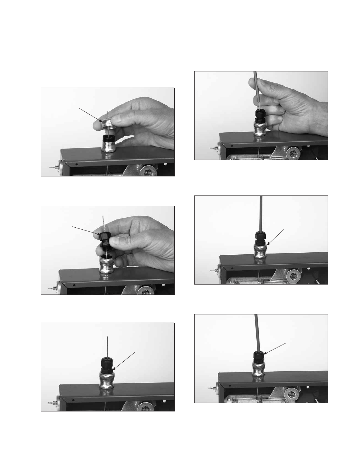
KITCHEN KNIGHT II Restaurant Fire Suppression Manual
SECTION 4 – SYSTEM INSTALLATION
UL EX3830 ULC EX3830
2014-NOV-10 REV. 06 PagE 4-25
Connecting the Flexible Conduit to the PYRO-CHEM
Control Head, Electrical Box, Pull Station, or Mechanical
Gas Valve (Continued)
5. Tighten the nut to the connector body, locking the flexible
conduit insert in place. See Figure 4-43.
TIgHTEN
CONNECTOR
NUT TO LOCK
IN FLEXIBLE
CONDUIT
INSERT
FIGURE 4-43
008072
6. Loosen the nut on the strain relief and thread the wire rope
through the strain relief. See Figure 4-44.
LOOSEN
NUT
8. Thread the wire rope through the flexible conduit. See
Figure 4-46. (If a splice is required in the flexible conduit,
proceed to “Splicing Installation Instructions.”)
FIGURE 4-46
008075
9. Slide the flexible conduit into the strain relief until it is
approximately 1/16 in. (1.6 mm) from the bottom of the flexible conduit insert. See Figure 4-47.
STOP FLEXIBLE
CONDUIT
aPPROXIMaTELY
1/16 IN. (1.6 mm)
FROM THE BOTTOM
OF INTERNaL
FLEXIBLE CONDUIT
INSERT
FIGURE 4-44
008073
7. Tighten the body of the strain relief to the conduit connector.
See Figure 4-45.
TIgHTEN
STRaIN RELIEF
INTO CONDUIT
CONNECTOR
FIGURE 4-45
008074
FIGURE 4-47
008076
10. Tighten the strain relief nut onto the strain relief. See Figure
4-48.
TIgHTEN NUT
ON STRaIN
RELIEF
FIGURE 4-48
008077
Page 76
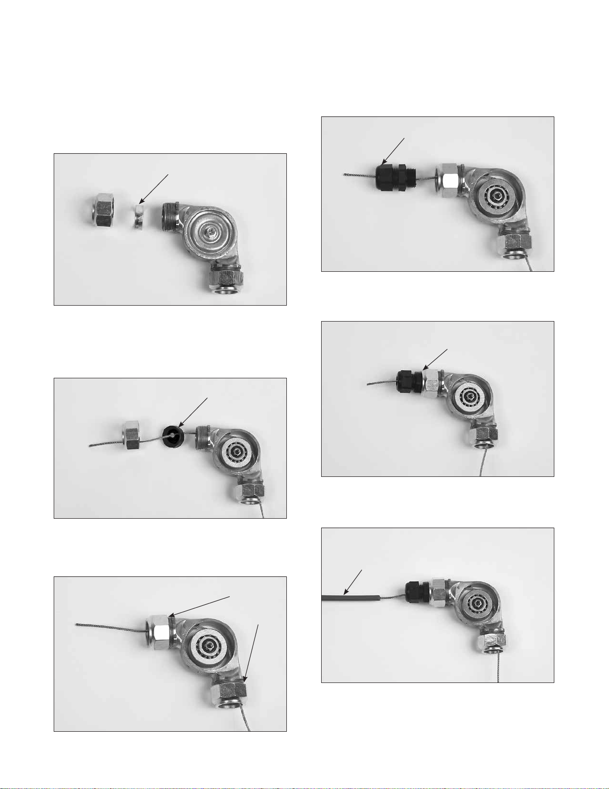
SECTION 4 – SYSTEM INSTALLATION
UL EX3830 ULC EX3830
PagE 4-26 REV. 06 2014-NOV-10
KITCHEN KNIGHT II Restaurant Fire Suppression Manual
Connecting Flexible Conduit to Pulley Elbows, Pulley
Tees, or Union Fittings
1. Unscrew the nut from pulley elbow, pulley tee, or EMT
conduit connector and remove the compression ring.
Discard ring. See Figure 4-49.
DISCaRD
RINg
FIGURE 4-49
007995
2. Thread the stainless steel wire rope through the EMT
conduit connector and flexible conduit insert. Make certain
thread in flexible conduit insert is facing out toward end of
connector. See Figure 4-50.
4. Loosen the nut on the strain relief and thread the wire rope
through the strain relief. See Figure 4-52.
LOOSEN NUT OF
STRaIN RELIEF
FIGURE 4-52
007998
5. Tighten the body of the strain relief to the conduit connector.
See Figure 4-53.
TIgHTEN STRaIN
RELIEF INTO CONDUIT
CONNECTOR
THREaDS FaCINg
aWaY FROM BODY
OF FITTINg
FIGURE 4-50
007996
3. Tighten the nut to the connector conduit body, locking the
flexible conduit insert in place. See Figure 4-51.
FLEXIBLE
CONDUIT
INSERT
LOCKED
IN PLaCE
FIGURE 4-53
007999
6. Push the wire rope into the flexible conduit. See Figure
4-54.
FLEXIBLE
CONDUIT
FIGURE 4-51
007997
FIGURE 4-54
008000
Page 77
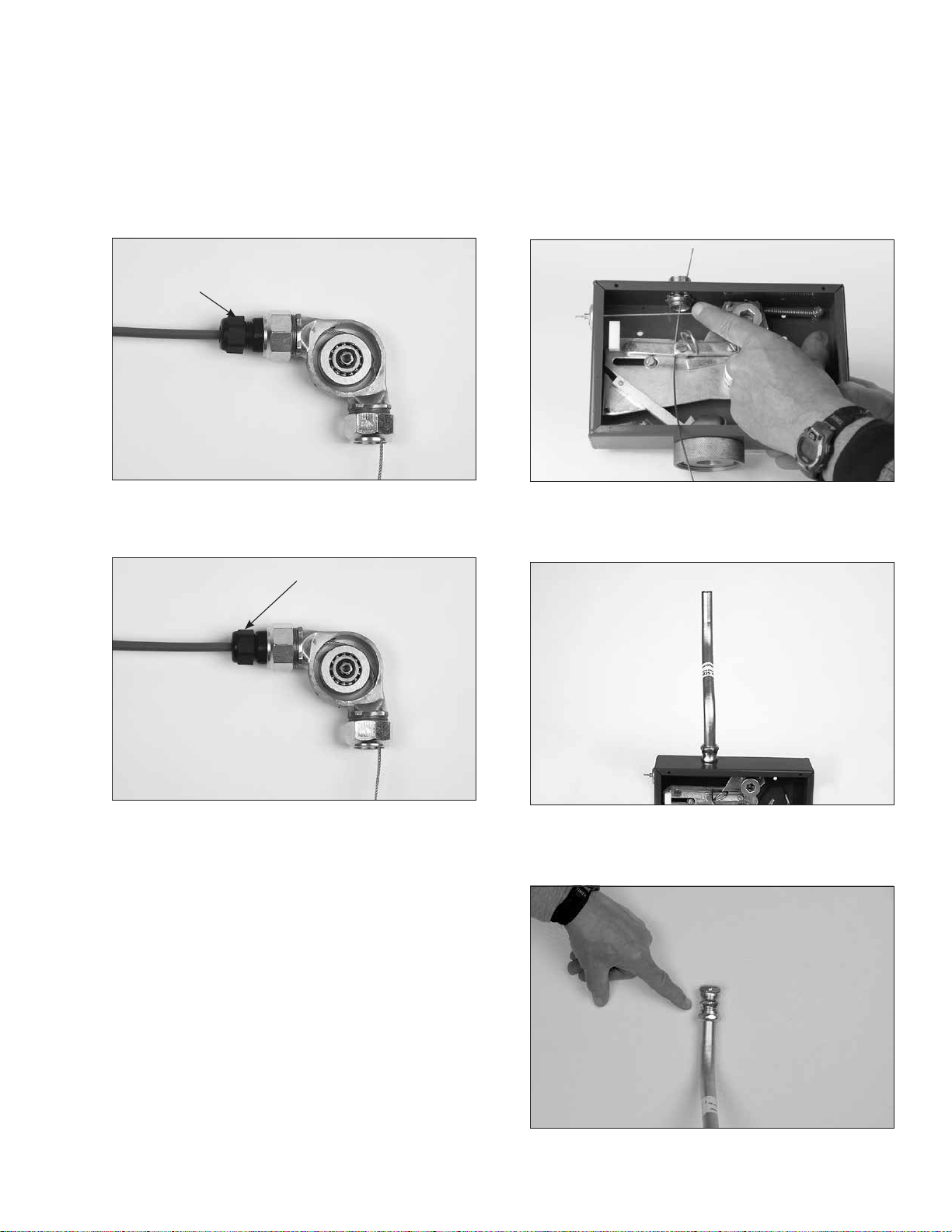
KITCHEN KNIGHT II Restaurant Fire Suppression Manual
SECTION 4 – SYSTEM INSTALLATION
UL EX3830 ULC EX3830
2014-NOV-10 REV. 06 PagE 4-27
Connecting Flexible Conduit to Pulley Elbows, Pulley
Tees, or Union Fittings (Continued)
7. Slide the flexible conduit into the strain relief until it is
approximately 1/16 in. (1.6 mm) from the bottom of the flexible conduit insert. See Figure 4-55.
SLIDE FLEXIBLE CONDUIT
aPPROXIMaTELY 1/16 IN.
(1.6 mm) FROM BOTTOM OF
FLEXIBLE CONDUIT INSERT
FIGURE 4-55
008001
8. Tighten the strain relief nut onto the strain relief. See Figure
4-56.
TIgHTEN STRaIN
RELIEF NUT
Installing Flexible Conduit Through a Conduit Offset
1. Starting at the PYRO-CHEM control head, connect
the conduit connector using the supplied nut. Use only
PYRO-CHEM Conduit Fittings (Part No. 55813). See Figure
4-57.
FIGURE 4-57
008068
2. Install Conduit Offset (Part No. 79825) into conduit connector and tighten nut. See Figure 4-58.
FIGURE 4-56
008002
9. Complete the same procedures on the other end of the
conduit fitting as described in Step 1 through Step 8 above.
FIGURE 4-58
008069
3. Install compression union to opposite end of conduit offset.
Tighten securely. See Figure 4-59.
FIGURE 4-59
008040
Page 78
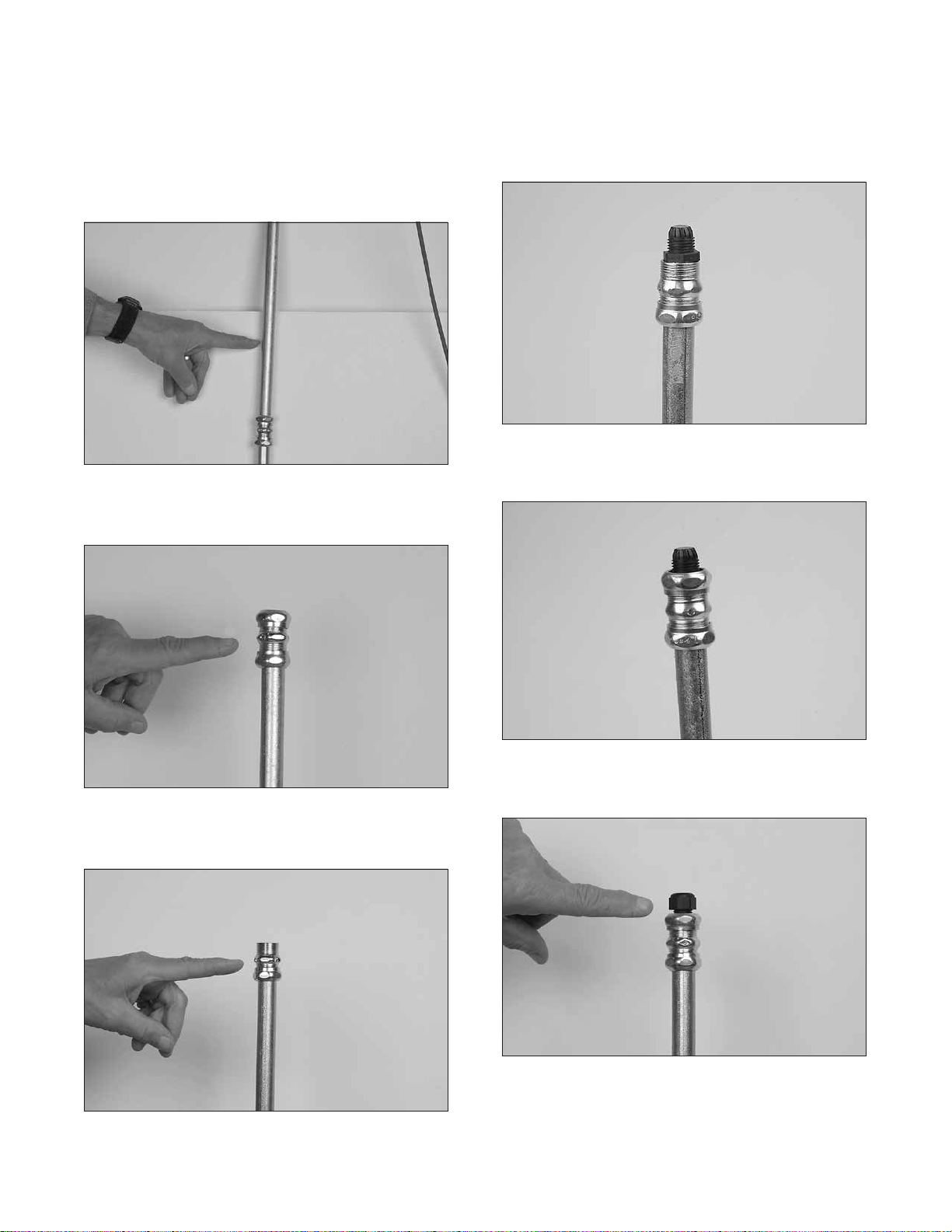
SECTION 4 – SYSTEM INSTALLATION
UL EX3830 ULC EX3830
PagE 4-28 REV. 06 2014-NOV-10
KITCHEN KNIGHT II Restaurant Fire Suppression Manual
Installing Flexible Conduit Through a Conduit Offset
(Continued)
4. Install the conduit required to get above the ceiling. See
Figure 4-60.
FIGURE 4-60
008041
5. Install compression union to top of conduit riser. See Figure
4-61.
7. Remove strain relief nut and install strain relief body into
compression union. See Figure 4-63.
FIGURE 4-63
008044
8. Install union nut over strain relief body and tighten nut. See
Figure 4-64.
FIGURE 4-61
008042
6. Remove union nut and ring. Discard ring. Do not reinstall
nut at this time. See Figure 4-62.
FIGURE 4-62
008043
FIGURE 4-64
008045
9. Install strain relief nut onto strain relief body. Do not tighten
nut at this time. See Figure 4-65.
FIGURE 4-65
008046
Page 79
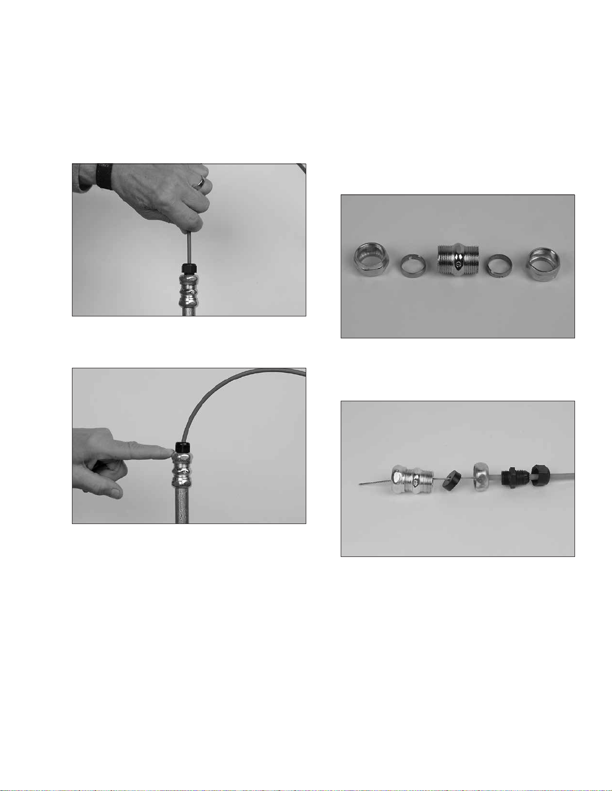
KITCHEN KNIGHT II Restaurant Fire Suppression Manual
SECTION 4 – SYSTEM INSTALLATION
UL EX3830 ULC EX3830
2014-NOV-10 REV. 06 PagE 4-29
Installing Flexible Conduit Through a Conduit Offset
(Continued)
10. Push flexible conduit completely through conduit offset.
Flexible conduit should stop flush or +/– 1/2 in. (12.7 mm)
from bottom of conduit of conduit fitting in PYRO-CHEM
control head. See Figure 4-66.
FIGURE 4-66
008047
11. Tighten nut on strain relief on top of conduit riser. See
Figure 4-67.
Flexible Conduit Splicing (Allowed on Pull Station
Installations Only)
Note: Wire rope cannot be spliced together, only the flexible conduit.
Flexible conduit can be spliced together using EMT Compression
Fitting Union (Part No. 79827) only for the pull connection.
1. Remove rings from both ends of compression union. See
Figure 4-68.
FIGURE 4-68
008061
2. Install strain relief nut, strain relief, compression union nut,
flexible conduit insert and compression union over the flexible conduit with wire rope installed. See Figure 4-69.
FIGURE 4-67
008048
12. Complete the remainder of the flexible conduit and wire
rope installation to the pull station or the gas valve.
FIGURE 4-69
008049
Page 80
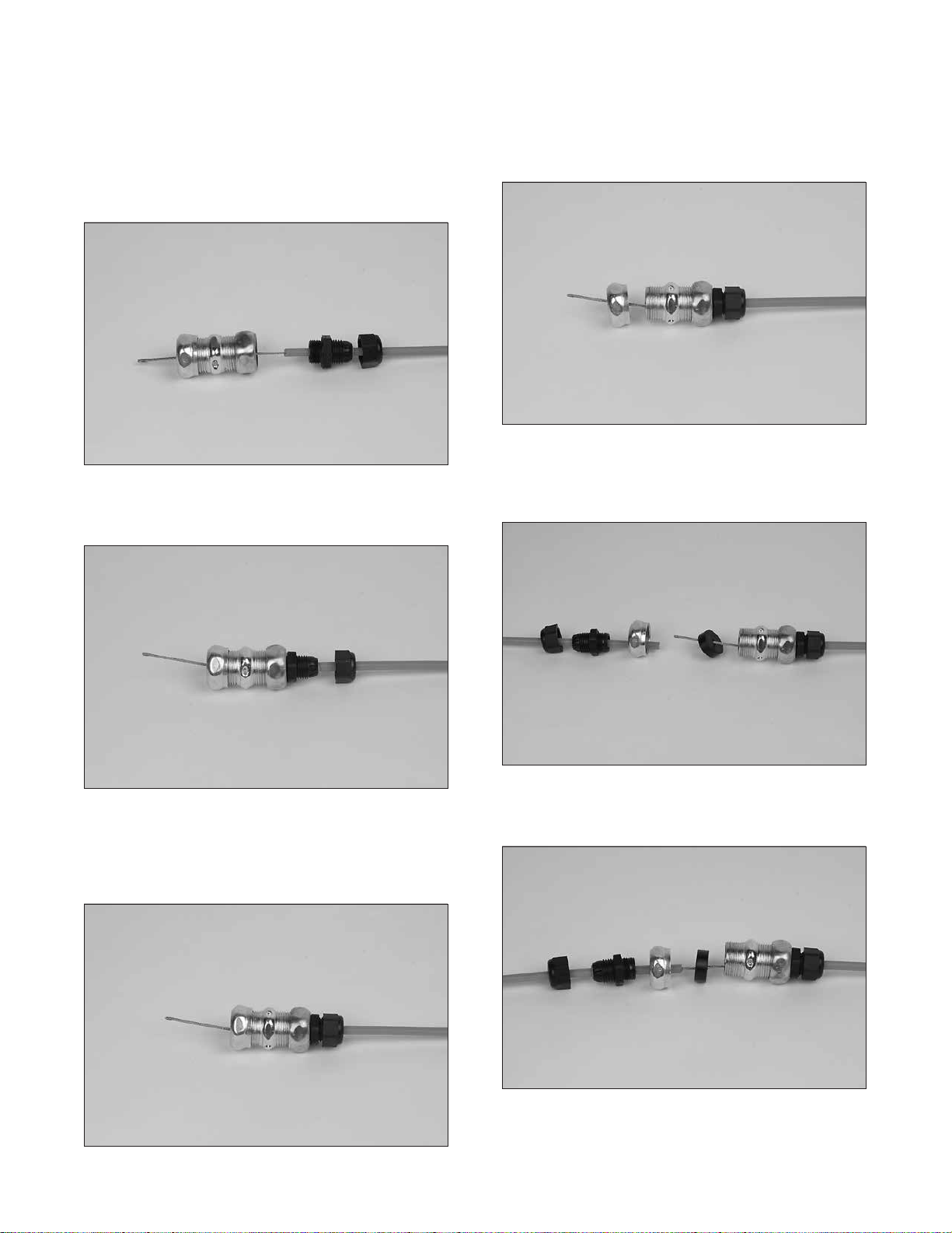
SECTION 4 – SYSTEM INSTALLATION
UL EX3830 ULC EX3830
PagE 4-30 REV. 06 2014-NOV-10
KITCHEN KNIGHT II Restaurant Fire Suppression Manual
Flexible Conduit Splicing (Allowed on Pull Station
Installations Only) (Continued)
3. Tighten compression union nut onto union body, locking
flexible conduit insert in place. See Figure 4-70.
FIGURE 4-70
008050
4. Install strain relief body into compression union and tighten.
See Figure 4-71.
6. Starting on the opposite end of the compression union,
remove the nut. See Figure 4-73.
FIGURE 4-73
008053
7. Install strain relief nut, strain relief, and compression union
nut on remaining section of flexible conduit and install flexible conduit insert on wire rope. See Figure 4-74.
FIGURE 4-71
008051
5. Push flexible conduit into strain relief until it is approximately
1/16 in. (1.6 mm) from the bottom of the flexible conduit
insert, then tighten strain relief nut onto strain relief body.
See Figure 4-72.
FIGURE 4-72
008052
FIGURE 4-74
008054
8. Push wire rope completely through remaining section of
flexible conduit. See Figure 4-75.
FIGURE 4-75
008055
Page 81
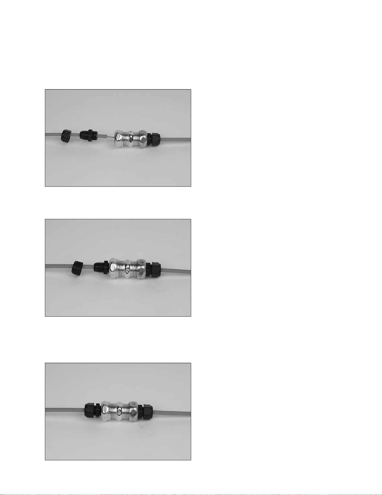
KITCHEN KNIGHT II Restaurant Fire Suppression Manual
SECTION 4 – SYSTEM INSTALLATION
UL EX3830 ULC EX3830
2014-NOV-10 REV. 06 PagE 4-31
Flexible Conduit Splicing (Allowed on Pull Station
Installations Only) (Continued)
9. Tighten compression union nut onto union body, securing
flexible conduit insert in place. See Figure 4-76.
FIGURE 4-76
008056
10. Tighten strain relief body into compression union. See
Figure 4-77.
12. Complete the remainder of the flexible conduit and wire
rope installation.
13. To test all installations, refer to the proper sections in the
KITCHEN KNIgHT II System Manual (Part No. 551274).
Testing Pull Station/Mechanical Gas Valve
To test all installations, refer to Page 4-18 for detailed testing
information.
FIGURE 4-77
008057
11. Push flexible conduit into strain relief until it is approximately
1/16 in. (1.6 mm) from bottom of the flexible conduit insert,
then tighten strain relief nut onto strain relief body. See
Figure 4-78.
FIGURE 4-78
008058
Page 82

SECTION 4 – SYSTEM INSTALLATION
UL EX3830 ULC EX3830
PagE 4-32 REV. 06 2014-NOV-10
NOTES:
KITCHEN KNIGHT II Restaurant Fire Suppression Manual
Page 83

KITCHEN KNIGHT II Restaurant Fire Suppression Manual
SECTION 5 – SySTEm maINTENaNCE
UL EX3830 ULC EX3830
2014-NOV-10 REV. 06 PagE 5-1
GENERaL
The maintenance information listed in this section deals with the
limitations and parameters of this pre-engineered system. Those
individuals responsible for the maintenance of the KITCHEN
KNIgHT II system must be trained and hold a current PYROCHEM certificate in a KITCHEN KNIgHT II training program.
SEmI-aNNUaL maINTENaNCE
1. Check that the hazard area has not changed.
2. Check that the system has not been tampered with, i.e.,
nozzles removed, nozzles not aimed properly, piping not
supported properly, blow off caps in place.
3. Check the entire system for mechanical damage.
4. Check all nozzle orifices to make certain they are not
plugged. apply a small amount of Dow Corning No. III silicone grease across the opening of the nozzle tip. Replace
blow off caps or o-ring if necessary.
Note: Rubber blow-off caps that have been installed in the
system for one year or more must be replaced.
5. Check the solenoid monitor.
CaUTION
Before continuing, remove the cover from the control
head and insert the safety pin in the hole in the slide
plate above the latching arm. This will secure the system,
preventing accidental discharge.
If the control head cover requires replacement, it must
only be replaced with the NMCH cover plate which does
not have a handle on the control head cover for local
actuation.
6. Disconnect the control head or pneumatic tubing from the
valve cap assembly of each agent cylinder. Remove the
carbon dioxide pilot cartridge in the control head. Remove
the safety pin from the slide plate. actuate the control head
to ensure it is functioning properly. Make certain the gas
shut-off valve and remote pull station are functioning properly.
Test the functionality of the control head with the cover in
place to verify there is no binding. If binding occurs, turn
the indicator mounting bolt until there is 1/16 (1.6 mm) clearance between the front edge of the control head back box
and white indicator surface.
7. Inspect the pulley elbows for excessive grease buildup.
Clean elbows if necessary. Replace fusible links. (They
must be replaced semi-annually per NFPa 96.) Visually
inspect thermal detectors.
Note: Refer to Section 4 – System Installation for control
head assembly resetting procedures.
8. Reinstall the carbon dioxide pilot cartridge, reconnect the
control head, and replace the control head cover and nylon
tie. See detailed cartridge installation instructions listed on
Page 4-20 (System Installation).
CaUTION
Before screwing the carbon dioxide pilot cartridge into the
actuator, ensure that the actuator has an o-ring installed.
If actuator is utilizing a Teflon washer, replace with o-ring
(Part No. 55531).
9. Inspect the cylinder pressure. Tap the gauge lightly to
ensure the needle is moving freely. If the gauge shows a
loss in pressure indicated by the needle being below the
green band, the tank should be removed and recharged per
the SYSTEM RECHaRgE section of Chapter VI (System
Recharge) in this manual.
aNNUaL maINTENaNCE
1. Inspect as per semi-annual maintenance instructions. Do
not reconnect control head at this time.
2. Disconnect the discharge piping from the valve outlet. Using
air or nitrogen, blow out the piping. Replace all nozzle caps.
3. Fixed temperature sensing elements of the fusible alloy
type must be replaced, at a maximum semi-annually, or
more frequently if necessary, to assure proper operation of
the system.
4. Test thermal detectors and remote pull stations per SYSTEM
CHECKOUT aFTER INSTaLLaTION section located in
Chapter IV (System Installation) of this manual. Per NFPa
72, two or more detectors per circuit should be tested. Note
individual detector location and date of testing. Within five
years, all detectors in system must be tested.
5. Replace the carbon dioxide pilot cartridge and o-ring (Part
No. 55531).
6. Record the date of installation on the cartridge with a felttipped marker.
7. See detailed cartridge installation instructions listed on
Page 4-20 (System Installation).
CaUTION
Before screwing the carbon dioxide pilot cartridge into the
actuator, ensure that the actuator has an o-ring installed.
8. Reconnect the control head. Replace the control head
cover and nylon tie.
NOTICE
Methods and frequency of inspection,
testing and maintenance of detectors
should be in accordance with NFPa-72.
Page 84

SECTION 5 – SySTEm maINTENaNCE
UL EX3830 ULC EX3830
PagE 5-2 REV. 06 2014-NOV-10
12-yEaR maINTENaNCE
along with the required annual maintenance requirements,
the tanks must be removed from the system and properly
discharged. all tank and hose assemblies must be hydrostatically tested per the requirements of NFPa-17a. The tank
must be refilled with fresh agent. Refer to the PYRO-CHEM
Hydrostatic Test Instructions Manual (Form No. PC2013008) for
additional hydrostatic testing information.
NOTICE
Refer to the nameplate on tank for hydrostatic
pressure requirements.
CaUTION
!
Precautions must be taken when handling and transferring
wet agents as they are cautic in nature. goggles must be
worn at all tmes. If any agent gets into the eyes, they should
be flushed with clean water for 15 minutes and a physician
contacted. If any agent contacts the skin, it should be flushed
with cold water to prevent irritation. The agent is electrically
conductive. Care must be taken to thoroughly clean up any
agent discharged around electrical appliances before turning
the power on.
KITCHEN KNIGHT II Restaurant Fire Suppression Manual
Page 85

KITCHEN KNIGHT II Restaurant Fire Suppression Manual
SECTION 6 – SySTEm REChaRgE
UL EX3830 ULC EX3830
2014-NOV-10 REV. 06 PagE 6-1
gENERaL
The recharge information listed in this section deals with the
limitations and parameters of this pre-engineered system.
Those individuals responsible for the recharge of the KITCHEN
KNIgHT II system must be trained and hold a current PYROCHEM certificate in a KITCHEN KNIgHT II training program.
SySTEm CLEaNUP
CaUTION
!
Before attempting any cleanup, make certain that all fuel
sources to the equipment to be cleaned have been shut off.
Make certain that the exhaust hood and all appliance electrical
controls have been de-energized to avoid any chance of electrical shock resulting from the cleaning process of electrically
conductive alkaline liquid agent and/or its residue.
Make certain all surfaces to be cleaned have cooled down to
room temperature.
Do not use water to clean any appliances that contain hot
grease or cooking oils. Doing so may result in violent steaming
and/or spattering.
SySTEm REChaRgE
NOTICE
Determine the cause of system discharge
and correct immediately before performing
system recharge.
5.
CaUTION
!
Precautions must be taken when handling and transferring wet agents as they are cautic in nature. goggles
must be worn at all tmes. If any agent gets into the eyes,
they should be flushed with clean water for 15 minutes
and a physician contacted. If any agent contacts the skin,
it should be flushed with cold water to prevent irritation.
The agent is electrically conductive. Care must be taken
to thoroughly clean up any agent discharged around electrical appliances before turning the power on.
The complete piping system must be flushed after a
discharge. Flushing Concentrate (Part No. 79656) must be
used when flushing the system. The concentrate is shipped
in a 32 oz (0.95 L) container. a PCL-160 tank requires half
of a container. a PCL-300 tank requires one container of
concentrate. a PCL-460 requires one and a half containers,
and a PCL-600 requires two containers. To prepare the
system for flushing:
a. Pour the required amount of flushing concentrate into
the tank.
b. Fill the tank approximately half full with warm, clear
water. agitate the tank for a few seconds and then add
more warm water to bring the level to the required fill line
using the Measuring Stick (Part No. 551039).
c. Reinstall valve and pickup tube. Hand tighten to 12.5
ft-lb (16.9 Nm) maximum torque.
CaUTION
1. after discharge, inspect the entire system for mechanical
damage. If the tank has sustained any mechanical damage,
it must be hydrostatically tested before refilling.
2. Disconnect the 1/4 in. actuation tubing or the control head
from the top of the tank valve.
3. Relieve the pressure from the top chamber of the tank valve
by depressing the core of the valve in the valve cap assembly. By performing this operation, the valve will close.
4. Slowly remove the valve and siphon tube. If there is any
residual pressure left in the tank, it will bleed out through the
pressure relief slot in the valve threads.
Do NOT use a wrench or other tool to tighten the valve.
Do NOT use a pipe extension on the valve outlet for the
purpose of providing additional torque.
d. Pressurize tank to 225 psi (15.5 bar) at 70 °F (21 °C) and
reinstall to piping network.
6. With nozzles in place, attach control head and manually
actuate the tank. allow the tank to completely discharge
through the piping network.
7. after the discharge is completed, the entire piping network
must be blown out with air or nitrogen until no more mist is
visual coming out of the nozzles.
8. Remove, clean, and reinstall all nozzles.
9. Remove the tank from the system. Slowly remove the valve
and siphon. If there is any residual pressure left in the tank,
it will bleed out through the pressure relief slot in the valve
threads. The valve and pressure regulator (located in outlet
of valve) must be cleaned and rebuilt after each discharge.
To rebuild the valve, use Rebuilding Kit (Part No. 550698).
To rebuild the pressure regulator, use Rebuilding Kit (Part
No. 551061). Each kit includes an instruction sheet listing
detailed rebuilding instructions.
Page 86

SECTION 6 – SySTEm REChaRgE
UL EX3830 ULC EX3830
PagE 6-2 REV. 06 2014-NOV-10
SySTEm REChaRgE (Continued)
10. Fill tank with required amount of KITCHEN KNIgHT agent –
3 gal (11.4 L) (Part No. 551188), or 1.6 gal (6.1 L) (Part No.
553176), using Measuring Stick (Part No. 551039). Tank
should be filled to a tolerance of –0/+1/8 in. (–0/+3.1 mm)
from the mark level on the measuring stick.
NOTICE
During filling, the agent temperature
should be 60 °F to 80 °F (16 °C to 27 °C).
NOTICE
The pressure gauge attached to the tank
valve should not be used to determine
when the charging pressure has been
reached. a calibrated external gauge
must be used.
KITCHEN KNIGHT II Restaurant Fire Suppression Manual
NOTICE
a pressure regulator must be used for
charging the tank assembly when the
pressure source is higher than the tankrated operating pressure of 225 psi (15.5
bar).
The pressure regulator in the valve outlet
must be removed before pressurizing.
11. Reinstall valve and pickup tube. Hand tighten to 12.5 ft-lb
(16.9 Nm) maximum torque. Pressurize Shrader valve
assembly with 150 psi (10.3 bar) of nitrogen. Install
Recharge adaptor (Part No. 551240), into the valve outlet
and pressurize with nitrogen to 225 psi (15.5 bar) at 70 °F
(21 °C). Wait 10 minutes and verify the pressure in the
tank is at 225 psi (15.5 bar). Relieve the pressure from the
Shrader valve assembly (this will cause the valve to close)
and then disconnect the recharge adaptor. Reinstall pressure regulator into valve outlet.
CaUTION
!
If pressure is not relieved from Shrader valve assembly
before the recharge adaptor is removed, the tank will
discharge.
12. Replace all fusible links by following the instructions listed in
the Installation Section.
13. Reset control head(s), accessories, pull stations and gas
valves by following the instructions listed in the Installation
Section.
 Loading...