

Page 1

XSD200
Betriebsanleitung
Operating Manual
Funk-Rauchwarnmelder
Smoke Alarm Device with Radio Link
Page 2
DE2DE
EN
Die Originalfassung dieser Anleitung ist
nach DIN EN 82079-1 in deutscher Sprache erstellt.
InhaltsverzeichnisInhaltsverzeichnis
1 Hinweise zur Betriebsanleitung 3
2 Sicherheitshinweise 6
3 Übersicht 10
4 Standortauswahl 13
5 Montage 20
6
Erstinbetriebnahme und Einrichtung
7
Funk-Gruppe erweitern und Lernmodus
8
Gemeinschafts-Funk-Gruppe einrichten
9 Verbindungstest 29
10
Auslieferungszustand wiederherstellen
11
Alarmweiterleitung und Alarm-Stopp
12 Stör- und Fehlermeldungen 34
13 Instandhaltung 39
14 Außerbetriebnahme 40
15 Zubehör, Ersatzteile und
Produktsupport 41
16 Technische Daten 80
17 Alarm- und Hinweistöne 83
18 Lichtsignale 87
DE
24
28
28
31
32
The original version of this instruction has
been prepared in German in accordance
with DIN EN 82079-1.
ContentContent
1 Notes on the operating manual 43
2 Safety instructions 46
3 Overview 50
4 Location selection 53
5 Installation 59
6 Initial activation and set ting up 63
7
Expanding a radi o group and learning mode
8 Setting up a shared radio group 67
9 Connection test 68
10 Restoring default settings 69
11 Alarm for warding and alarm stop 70
12 Fault and error messages 71
13 Maintenance 76
14 Deac tivation 77
15 Accessories , spare parts and
product support 79
16 Technical specications 80
17 Alarm and alert tones 83
18 Light signals 87
EN
66
1 Hinweise zur
Betriebsanleitung
Wir freuen uns, dass Sie sich für unser
Produkt entschieden haben und danken
Ihnen für Ihr Vertrauen!
Die vorliegende Betriebsanleitung
enthält Informationen und Hinweise
zur sicheren Montage, Inbetriebnahme, Einrichtung und Instandhaltung,
sowie zum einwandfreien Betrieb
des Funk-Rauchwarnmelders.
Die Betriebsanleitung soll die Zuverlässigkeit
sowie die Lebensdauer erhöhen, soll Gefahren und Ausfallzeiten und ggf. einen Verlust
von Gewährleistungsansprüchen vermeiden.
Die Betriebsanleitung muss zwingend
gelesen und verstanden werden.
Für eine bessere Lesbarkeit wird der
XSD200 Funk-Rauchwarnmelder im
weiteren Fließtext als „Rauchwarnmelder“ bzw. „Gerät“ bezeichnet.
1.1 Gültigkeit der
Betriebsanleitung
Die Betriebsanleitung gilt nur für
den Funk-Rauchwarnmelder des Typs XSD200.
1.2 Typenschild und
Identikation
Das Typenschild des Rauchwarnmelders
bendet sich unter der Prüf-/Stopp-Taste
(Abdeckung Rauchwarnmelder).
Rauchwarnmelder mit Q-Label
Einen Rauchwarnmelder mit
Q-Label erkennen Sie am
auf dem Typenschild.
1.3 Konformität
Der Rauchwarnmelder des Typs XSD200
Der Rauchwarnmelder des Typs XSD200
ohne Q-Label ist zertiziert nach:
mit Q-Label ist zertiziert nach:
• 2014/53/EU (RED-Richtlinie)
• vfdb-Richtlinie 14/01 (Q)
• Verordnung (EU) Nr. 305/2011
• 2014/53/EU (RED-Richtlinie)
gemäß EN 14604:2005/AC:2008
• Verordnung (EU) Nr. 305/2011
gemäß EN 14604:2005/AC:2008
15
1772-CPR-140141
Variante: V3
21
1772-CPR-210050
Variante: V3-Q
Betriebsanleitung: XSD200 - Funk-Rauchwarnmelder
3
Page 3

DE
DE
Nähere Informationen zum Q-Label und
der vfdb-Richtlinie nden Sie auf unserer Homepage unter pyrexx.com.
Konformität gemäß
2014/53/EU (RED-Richtlinie)
Die Pyrexx GmbH erklärt, dass sich
der Rauchwarnmelder in Übereinstimmung mit den grundlegenden Anforderungen und den übrigen
einschlägigen Bestimmungen der
Richtlinie 2014/53/EU befindet.
Die Konformitätserklärung ist unter
folgender Adresse abrufbar:
pyrexx.com/de/support/downloads
Konformität gemäß
EN 14604:2005/AC:2008 (CE)
Der Rauchwarnmelder ist nach Ver-
ordnung (EU) Nr. 305/2011 gemäß
EN 14604:2005/AC:2008 (CE) als Bauprodukt zertiziert. Die Produktion wird
durch regelmäßige und unabhängige
Kontrollen auf unveränderte Einhaltung
der gesetzlichen und normativen Vorgaben überwacht.
Die Leist
ungserklärung für einen
Rauchwarnmelder mit Q-Label ist unter
4
Betriebsanleitung: XSD200 - Funk-Rauchwarnmelder Betriebsanleitung: XSD200 - Funk-Rauchwarnmelder
folgender Bezugsnummer beim Herstel-
ler abrufbar: k_503413
1.4 Aufbewahrung der
Betriebsanleitung
Die Betriebsanleitung ist ein wichtiger
Bestandteil des Rauchwarnmelders und
muss in der Nähe des Montageortes stets
gribereit aufbewahrt werden.
1.5 Verwendete Symbole
In der Betriebsanleitung werden im
Text unterschiedliche Kennzeichnungen und Symbole verwendet.
Diese sind nachfolgend erläutert.
Warnsymbol in Warnhinweisen
Zusätzliche Informationen und
Hinweise
(1) Nummerierte Handlungsschritte
f Symbol für eine Anweisung bzw.
erforderliche Handlung
5 Ergebnis einer Handlung
• Symbol für eine Aufzählung
1.6 Urheberrecht
Alle Rechte sind vorbehalten, insbesondere die Rechte auf Vervielfältigung und Verbreitung sowie Übersetzung. Kein Teil dieser Betriebsanleitung darf in irgend einer
Form ohne schriftliche Genehmigung der
Pyrexx GmbH reproduziert werden oder
unter Verwendung elektronischer Systeme verarbeitet, vervielfältigt oder verbreitet werden.
1.7 Garantie und
Gewährleistung
Die Pyrexx GmbH garantiert nur dem
ursprünglichen Käufer dieses Gerätes,
das bei einem autorisierten Fachhändler
erworben wurde, für die Dauer von 10
Jahren ab dem Kaufdatum, unter bestimmungsgemäßen Einsatz- und
Wartungsbedingungen ein mängelfreies
Gerät. Von der Garantie ausgeschlos-
sen sind äußere Umgebungseinflüsse,
wie z.B. Insekten- oder Staubbefall.
Die Garantie erlischt zu dem auf dem
Label aufgedruckten Austauschdatum des
Rauchwarnmelders.
Weiterführende Informationen bezgl. der
Pyrexx Garantiebedingungen
finden Sie im Downloadbereich.
pyrexx.com/de/support/downloads
5
Page 4
DE
DE
2 Sicherheitshinweise
2.1 Darstellung und Aufbau von
Warnhinweisen
Die Warnhinweise sind handlungsbezogen und wie folgt aufgebaut und
abgestuft:
GEFAHR
Art und Quelle der Gefahr!
Erläuterung zur Art und Quelle.
f Maßnahmen zur Abwendung der
Gefahr.
GEFAHR
Unmittelbare Lebensgefahr oder
schwere Verletzungen.
VORSICHT
Mögliche leichte Verletzungen, Sach-
oder Umweltschäden.
6
Betriebsanleitung: XSD200 - Funk-Rauchwarnmelder Betriebsanleitung: XSD200 - Funk-Rauchwarnmelder
2.2 Bestimmungsgemäße
Verwendung
Das Gerät dürfen Sie nur für folgende
Zwecke verwenden:
• Raucherfassung und Hitzewarnung
in pri vaten Haushalten und bewohnten Immobilien inkl. der Alarmweiterleitung per Funk-Verbindung
• Rauchwarnmelder im Innenbereich
• Funk-Gruppe oder Gemeinschafts-
Funk-Gruppe von
Rauchwarnmeldern
• Einsatz in bewohnbaren Freizeit-
fahrzeugen (z. B. Wohnwagen)
• Verwendung gemäß DIN 14676 und
geltender Bauordnungen, Bauvorschriften und Brandvorschriften
Beachten Sie bei der Verwendung des
Rauchwarnmelders Folgendes:
f Gerät ausschließlich bestimmungs-
gemäß und in einem technisch
einwandfreiem Zustand verwenden.
f Für Sondereinstellungen an den
Hersteller wenden.
2.3 Nichtbestimmungsgemäße
Verwendung
Das Gerät dürfen Sie nicht für folgende
Zwecke verwenden:
• Wärmemelder im Sinne der EN 54-5
• drahtloser Rauchmelder/Brand-
melder im Sinne der EN 54-25
• jede Verwendung, die nicht in dieser
Betriebsanleitung ausdrücklich als
zulässig beschrieben ist
2.4 Maximale Nutzungsdauer
Nutzungsdauer von 10 Jahren sowie eine Lagerung von 1 Jahr
f Tauschen Sie das Gerät nach Ablauf
der maximalen Nutzungsdauer aus.
2.5 Grundsätzliche
Sicherheitshinweise
Die grundsätzlichen Sicherheitshinweise fassen alle Maßnahmen zur Sicher
heit thematisch zusammen und gelten
jederzeit.
Allgemein
Rauchwarnmelder warnen frühzeitig
vor Brandrauch bzw. Bränden, damit
die Bewohner von Haus und Wohnung
rechtzeitig reagieren, insbesondere die
brandbeaufschlagten Räume sofort
verlassen und die Feuerwehr alarmieren
können. Rauchwarnmelder verhindern
weder die Entstehung von Bränden noch
bekämpfen sie diese selbsttätig. Rauchwarnmelder alarmieren weder unmittelbar die Feuerwehr oder eine hilfeleistende Stelle. Rauchwarnmelder dienen nicht
der Verhinderung von Brandschäden,
insbesondere nicht, wenn bei Brandausbruch niemand anwesend ist. Die
Rauchwarnmelder unterliegen bei der
Herstellung strengen Qualitätskontrollen.
Zusätzlich wird vor der Auslieferung eine
-
7
Page 5
DE
DE
•
•
•
•
•
•
•
•
•
• SchmutzjeglicherArt
zur Beschädigung des Gerätes.
Gewährleistungspicht auch zur Folge,dass
f
Komponenten(z.B.Sensoren).
f
f
Gewährleistungspicht auch zur Folge,dass
gesetzt werden kann und darf.
Funktionsprüfung durchgeführt. Dennoch
ist es möglich, dass unerwartete Funktionsstörungen auftreten können.
Was tun wenn es brennt?
(1) Bewahren Sie Ruhe.
(2) Warnen Sie alle Mitbewohner.
(3) Helfen Sie Kindern, behinderten,
älteren und kranken Menschen.
(4) Schließen Sie alle Fenster und Türen
hinter sich.
(5) Verlassen Sie umgehend das Haus.
(6) Benutzen Sie keine Aufzüge.
(7) Alarmieren Sie die Feuerwehr: 112
Batteriewechsel
Ein Batteriewechsel ist nicht erforder lich
und technisch ausgeschlossen, da das
Gerät nicht geönet werden darf.
Äußere Einüsse
8
Betriebsanleitung: XSD200 - Funk-Rauchwarnmelder Betriebsanleitung: XSD200 - Funk-Rauchwarnmelder
Äußere Einüsse können zu Funktionsstörungen und einer Beschädigung des
Gerätes sowie der Batterie führen. Schützen Sie das Gerät vor:
• Nässe
• Kälte
• direkter Sonneneinstrahlung
und übermäßiger Wärme
(Beschädigung der Batterie)
• Staub und Feinstaub
• Spinnen- und Insektenbefall
• Fett
• Nikotin- und Lackdämpfen
• Anstrichen (z. B. Wandfarbe)
• Klebstoen
• Schmutz jeglicher Art
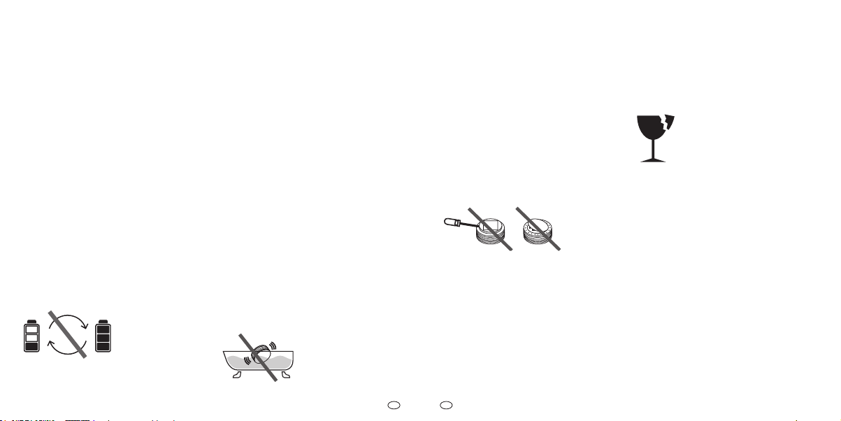
Eintauchen in Wasser
Das Eintauchen des Gerätes in Wasser
führt zur Beschädigung des Gerätes.
f Tauchen Sie das Gerät nicht ins
Wasser.
Gerät önen
Das Gerät ist ein geschlossenes Sys tem.
Jeder Eingri in das Gerät hat neben dem
Verlust der beschränkten Garantie und
der gesetzlichen Gewährleistungspicht
auch zur Folge, dass das Gerät nicht mehr
bestimmungsgemäß eingesetzt werden
kann und darf.
f Önen Sie das Gerät nicht.
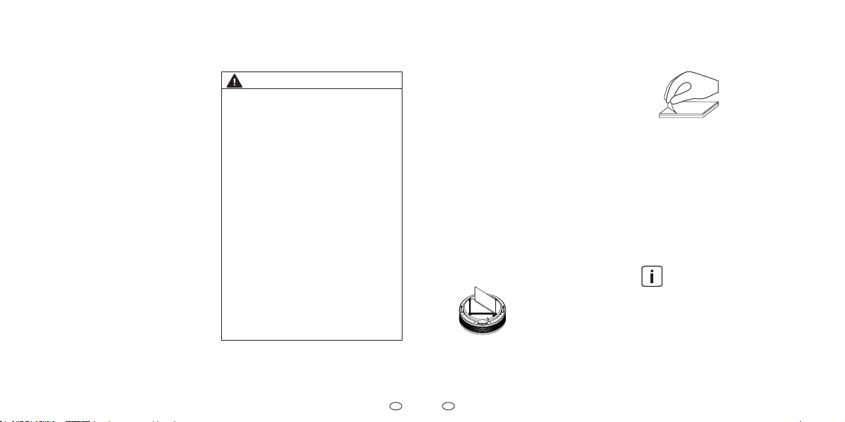
Als Ausnahme dürfen Sie den Dekodeckel (Abdeckung des Rauchwarnmel-
ders) zum Identizieren des Gerätes oder
zum Dekorieren abnehmen.
Empndliche Komponenten
Das Gerät besteht aus empfindlichen
Komponenten (z.B. Sensoren).
f Werfen Sie das Gerät nicht.
f Lassen Sie das Gerät nicht fallen.
f Üben Sie keinen Druck auf das Gerät
aus.
Dekorieren
Durch verdeckte Raucheinlasslamellen
kann die Raucherfassungs- und Hitzewarnfunktion beeinträchtigt oder verhindert werden. Es kann kein zuverlässiger
Alarm ausgelöst werden.
f Dekorieren Sie ausschließlich
den Dekodeckel (Abdeckung des
Rauchwarnmelders) und halten Sie
die Raucheinlasslamellen frei.
9
Page 6
DE
DE
3 Übersicht
Renovierungsarbeiten
Bei Renovierungs-, Bau- und Schleifarbeiten kann es auf Grund von Staubentwicklung zu Funktionsstörungen oder
Beschädigung des Gerätes kommen.
f Nehmen Sie das Gerät vor Renovie-
rungsarbeiten ab oder schützen Sie
es mit einer geeigneten Abdeckung.
Während das Gerät abgedeckt
ist, kann kein zuverlässiger Alarm
ausgelöst werden.
f Montieren Sie das Gerät nach Been-
digung der Renovierungsarbeiten
am ursprünglichen Einsatzort bzw.
entfernen Sie die Abdeckung.
10
Betriebsanleitung: XSD200 - Funk-Rauchwarnmelder Betriebsanleitung: XSD200 - Funk-Rauchwarnmelder
3.1 Funktion
Die Grundfunktionen des Gerätes sind:
• Hitzewarnfunktion
• Raucherfassung nach dem
optischen Detektionsverfahren
• maximal 15 Geräte zu einer
Funk-Gruppe verbinden
• maximal 15 Funk-Gruppen
miteinander verbinden (inklusive
Gemeinschafts-Funk-Gruppe)
• Alarmweiterleitung an alle Geräte
einer Funk-Gruppe
• Alarmweiterleitung von Funk-Gruppe
zur Gemeinschafts-Funk-Gruppe
• Repeaterfunktion
Falls Sie Bedarf an bestimmten,
komplexen und ggf. kaskadierenden Verbindungsfunktionen bei
der Alarmweiterleitung haben,
wenden Sie sich an den Hersteller
(siehe Kapitel 15 „Zubehör,
Ersatzteile und Produktsupport“
auf Seite 41).
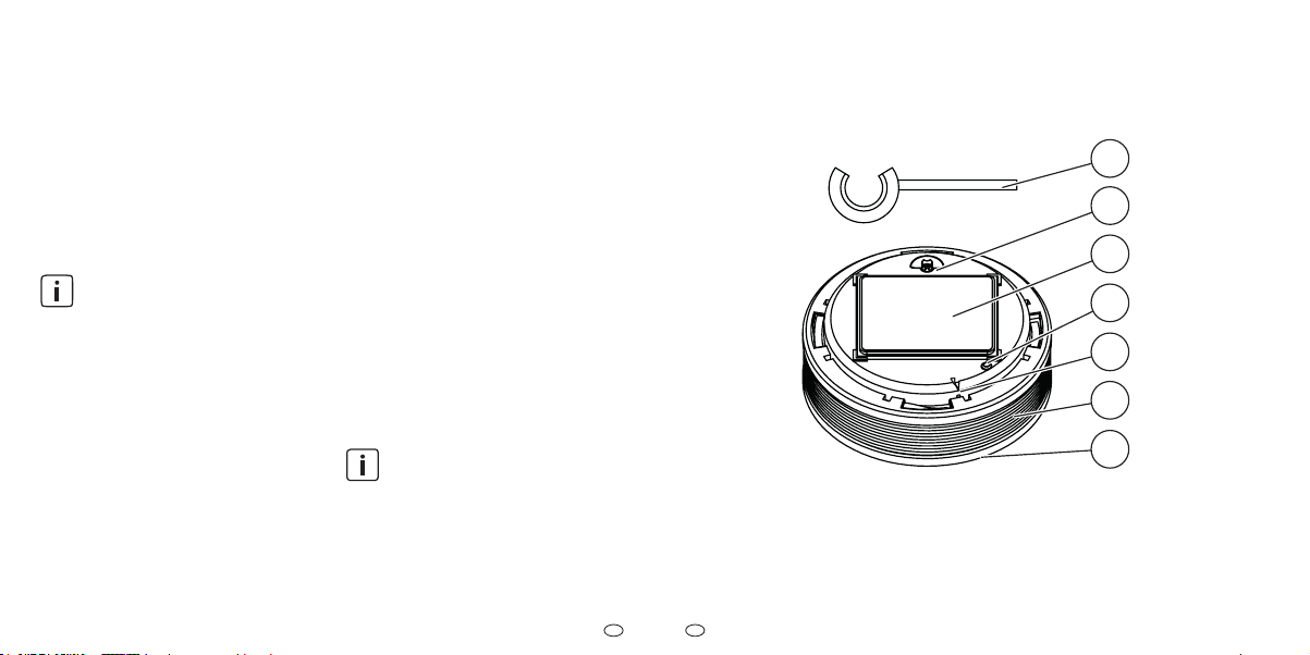
3.2 Bedienelemente
Abb. 1 Bedienelemente
1 Splint (Aktivierungssicherung)
2 Aktivierungstaste
3 Magnetträger
4 Signal-LED
1
2
3
4
5
6
7
5 Funk-Taste
6 Raucheinlasslamellen
7 Prüf-/Stopp-Taste
(Abdeckung Rauchwarnmelder)
11
Page 7
DE
DE
4 Standortauswahl
Splint (Aktivierungssicherung)
Der Splint (Aktivierungssicherung) dient
während des Transports des Gerätes
dem Schutz vor ungewollter Aktivierung.
Nach der Inbetriebnahme des Gerätes wird der Splint (Aktivierungssicherung) als Hilfsmittel zur Betätigung der Funk-Taste verwendet
und muss in der Nähe des Gerätes
gribereit aufbewahrt werden.
Aktivierungstaste
Die Aktivierungstaste dient dem Ein- und
Ausschalten des Gerätes.
Magnetträger
Der Magnetträger dient der Befestigung
des Gerätes.
Signal-LED
Die Signal-LED zeigt während der Inbetriebnahme von Geräten und dem Einrichten von Funk-Gruppen oder Gemeinschafts-Funk-Gruppen Ergebnisse und
Zwischenergebnisse an.
12
Betriebsanleitung: XSD200 - Funk-Rauchwarnmelder Betriebsanleitung: XSD200 - Funk-Rauchwarnmelder
Funk-Taste
Die Funk-Taste, welche sich in der mit ei-
nem Pfeil markierten Önung bendet,
wird zum Einrichten von Funk-Verbindungen zwischen Geräten verwendet.
Raucheinlasslamellen
Durch die Raucheinlasslamellen gelangt
Brandrauch in das Innere des Gerätes
und kann von Sensoren erfasst werden.
Prüf-/Stopp-Taste
(Abdeckung Rauchwarnmelder)
Die Prüf-/Stopp-Taste (Abdeckung
Rauchwarnmelder) dient dem Selbsttest,
der korrekten Funkverbindung zwischen
mehreren Geräten oder den Geräten einer Funk-Gruppe.
Die Prüf-/Stopp-Taste (Abdeckung
Rauchwarnmelder) kann betätigt werden, um Alarm- und Hinweistöne zu unterbrechen oder zu beenden.
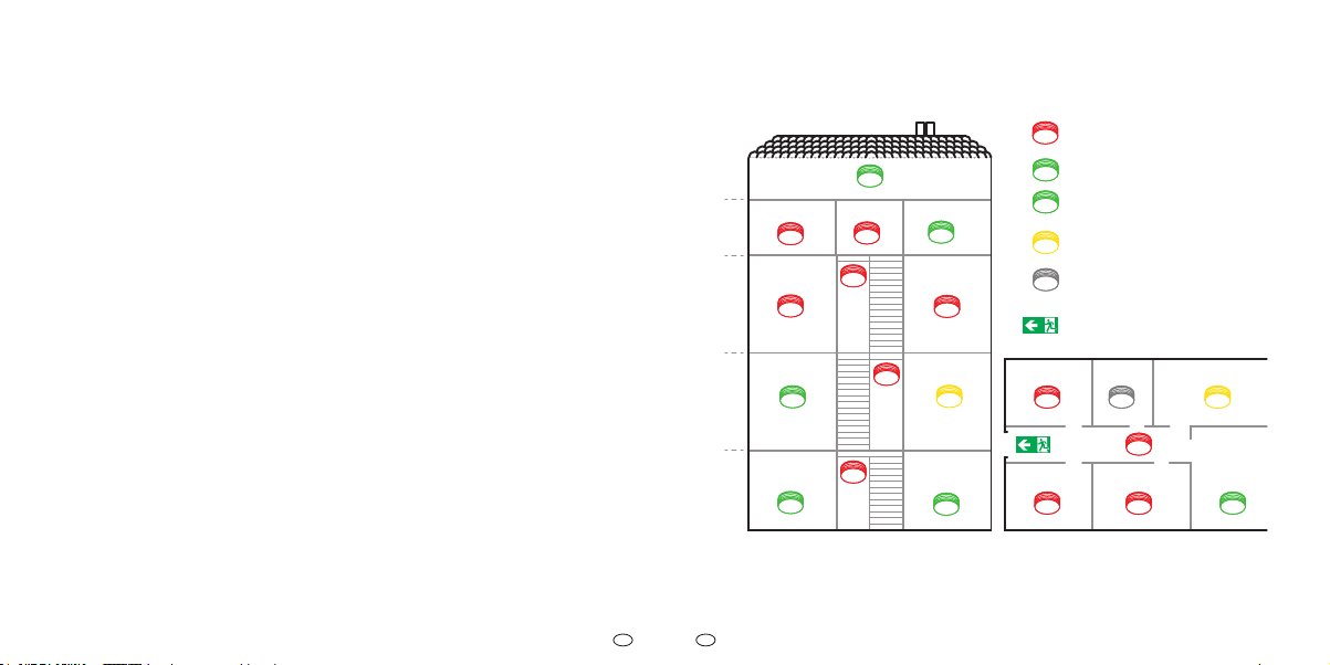
Dachboden
DG
Gästezimmer
OG
Schlafzimmer Kinderzimmer
Wohnzimmer Küche
EG
*
Heizung
KG
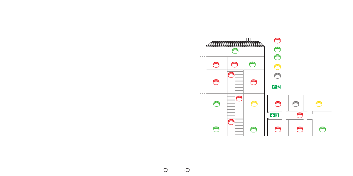
Abb. 2 Standortauswahl
Büro
Werkraum
Mindestausstattung
optimale Ausstattung
in Berlin und Brandenburg
*
Picht
unter Vorbehalt
wegen Wasserdampf nicht
montieren
Fluchtweg
Schlafzimmer Bad Küche
Kinderzimmer
*
Flur
Kinderzimmer
Wohnzimmer
*
13
Page 8

DE
DE
Der Einsatz von Rauchwarnmeldern ist
nach DIN 14676 geregelt.
Mindestausstattung
• Schlafräume
• Kinderzimmer
• Gästezimmer
• Flure und alle anderen Räume,
die als Fluchtweg dienen
• Treppenhäuser von
Einfamilienhäusern
Optimale Ausstattung
• alle Wohn- und Hobbyräume
(außer in Berlin und Brandenburg,
hier ist eine Ausstattung ebenfalls
gesetzlich vorgeschrieben)
• Heizungs- und Werkräume
• Büro bzw. Arbeitszimmer
• Keller
• Dachboden
14
Betriebsanleitung: XSD200 - Funk-Rauchwarnmelder Betriebsanleitung: XSD200 - Funk-Rauchwarnmelder
Ausstattung unter Vorbehalt
• In Küchen sind Rauchwarnmelder
nur zu installieren, wenn Fehlalarme
(z. B. durch Wasserdampf)
auszuschließen sind.
Nicht empfohlen
• Badezimmer sind auf Grund der
hohen Entwicklung von
dampf
von der Ausstattung mit
Wasser-
Rauchwarnmeldern ausgenommen.
4.1 Überwachungsäche
Setzen Sie ein Gerät ein, wenn mindes
tens einer der folgenden Punkte zutrit:
• Überwachungsäche kleiner 60 m2
und Raumhöhe kleiner 6 m
• Deckenfelder (Höhe kleiner 20 cm)
bei Unterzügen (Fläche Decken-
felder kleiner 36 m2)
Setzen Sie zusätzliche Geräte ein, wenn
mindestens einer der folgenden Punkte
zutrit:
• Überwachungsäche größer 60 m
2
• Raumhöhe größer 6 m
• hohe Teilwände
• raumtrennende Möbelstücke
• Deckenfelder (Höhe größer 20 cm)
bei Unterzügen (Fläche
Deckenfelder größer 36 m2)
• Podest/Galerie (Fläche größer 16
m2, mindestens 2 m lang und breit)
Bei Räumen mit Unterzügen
(z. B. Holzbalken) ist die
Anzahl und Anordnung der
Geräte abhängig von der
Höhe der Unterzüge und von der
Fläche der durch die Unterzüge
entstandenen Felder.
4.2 Anforderung an die
Überwachungsäche
Beachten Sie bei der Auswahl der geeig-
neten Überwachungsäche Folgendes:
f Gerät mittig an der Raumdecke
positionieren.
f Master bzw. Gemeinschafts-Funk-
Gruppe an einer zentralen Stelle
(z. B. im Flur) positionieren.
f Zwischen Master und den übrigen
Geräten einer Funk-Gruppe (wenn
möglich) einen ungefähr gleichen
Abstand einhalten.
f Zwischen Gemeinschafts-Funk-Grup-
pe und den übrigen Funk-Gruppen
einen ungefähr gleichen Abstand
einhalten.
f Ggf. zusätzliche Geräte installieren.
f Mindestabstand von 2 m zu elektro-
nischen, funkbasierenden Geräten
(z. B. WLAN-Router) einhalten.
f Mindestabstand von 3m zu
anderen Funk-Rauchwarnmeldern
einhalten.
f Maximale Installationshöhe von 6 m
einhalten.
f Mindestabstand von 0,5 m zu umlie-
genden Wänden, Möbelstücken und
Lampen einhalten.
f Höchstabstand von 6m zu einem
15
Page 9

DE
DE
50
1/21/2
f
Stirnäche(EndedesFlures)unddem
f
f
Stirnäche(EndedesFlures)unddem
f
f
möglichen Brandherd einhalten.
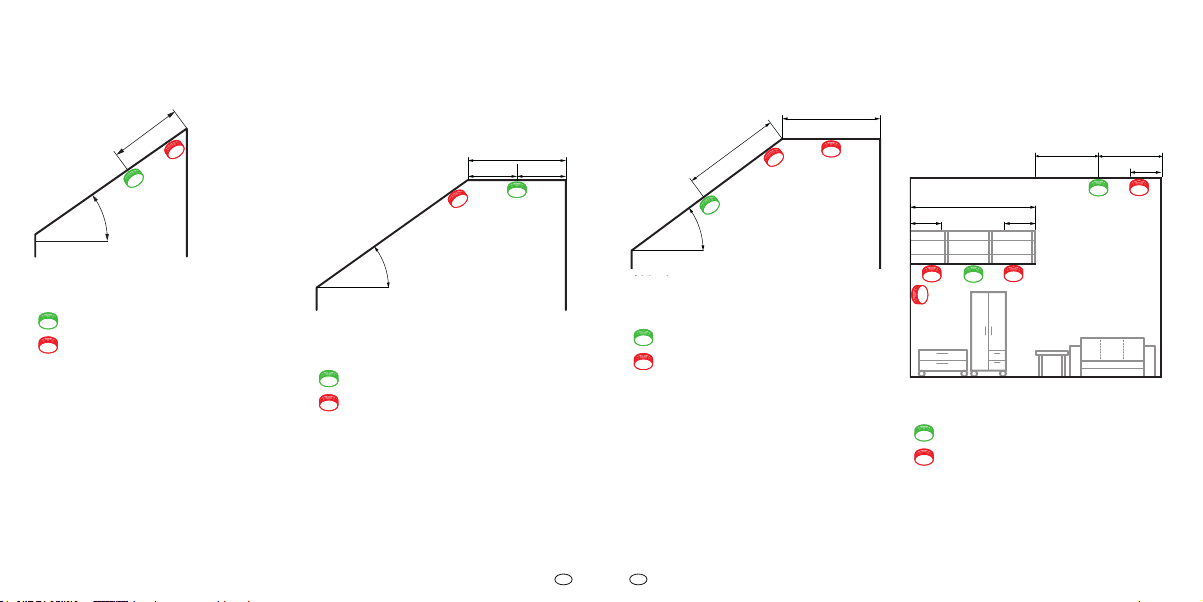
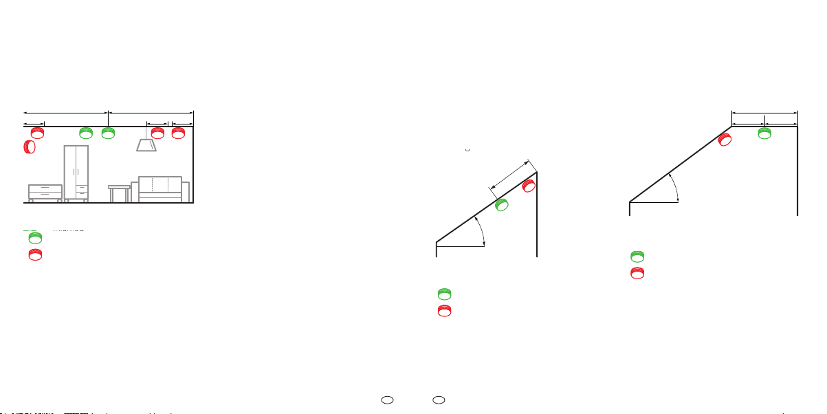
Zuggefährdete Umgebung
Räume mit geraden Raumdecken
(Neigungswinkel < 20°)
Damit aufkommender Rauch den Rauchwarnmelder erreichen kann, dürfen am
Installationsort keine stark zugbilden-
0,
den Einflüsse (z. B. durch Klima- und
Belüftungseinlässe oder Ventilatoren)
herrschen. In zwangsbelüfteten Räumen
müssen perforierte Decken, die der Be-
lüftung dienen, im Radius von 0,5m um
den Melder geschlossen werden.
Abb. 3 Räume mit geraden Raum-
decken
erlaubt
nicht erlaubt
Beachten Sie Folgendes bei der Standortauswahl in Räumen mit geraden
Raumdecken:
f Bei Deckenabsätzen den höchst ge-
legenen Montagepunkt auswählen.
f Geräte waagerecht zum Monta-
geuntergrund montieren.
16
Betriebsanleitung: XSD200 - Funk-Rauchwarnmelder Betriebsanleitung: XSD200 - Funk-Rauchwarnmelder
Schmale Räume oder Flure
(zwischen 1 und 3 m breit)
Beachten Sie zusätzlich Folgendes bei
,50,5
der Standortauswahl in schmalen Räumen oder Fluren, die zwischen 1 und 3 m
breit sind:
f Weniger als 7,5 m Abstand zwi-
schen Stirnäche (Ende des Flures)
und dem ersten Gerät einhalten.
f Weniger als 15 m Abstand zwischen
2 Geräten einhalten.
Schmale Räume oder Flure
(< 1 m breit)
Beachten Sie zusätzlich Folgendes bei
der Standortauswahl in schmalen Räumen oder Fluren, die weniger als 1 m
breit sind:
f Abstand zu umliegenden Wänden
Schmale Räume oder Flure
(Grundäche < 6 m2)
Eine Ausnahme bilden schmale Räume
und Flure, die eine Grundäche von weniger als 6 m2 haben.
Bei dieser Montagesituation können Sie
die Geräte auch an der Wand montieren.
f Gerät mittig an der längeren Wand
positionieren.
f Gerät 0,5 m unterhalb der Raumde-
cke montieren.
Räume mit schrägen Raumdecken
(Neigungswinkel > 20°)
In Räumen mit einer Deckenneigung von
mehr als 20° zur Horizontalen können
sich in der Deckenspitze Wärmepolster
bilden, die den Raucheintritt am Rauchwarnmelder behindern.
einhalten (Ausnahme: Abstand
weniger als 0,5 m).
17
Page 10
DE
DE
0
gerade Montageäche mindestens
f
Stirnäche(EndedesFlures)unddem
f
f
waagerechten Raumdecken
21
f
Stirnäche(EndedesFlures)unddem
f
f
Montageächemindestens 1mlang und1m
f
(Neigungswinkel<20°)“aufSeite18
beachten
f
Stirnäche(EndedesFlures)unddem
f
f
1/2
1/2
f
Stirnäche(EndedesFlures)unddem
f
f
5
> 0,
< 1,00
> 20°
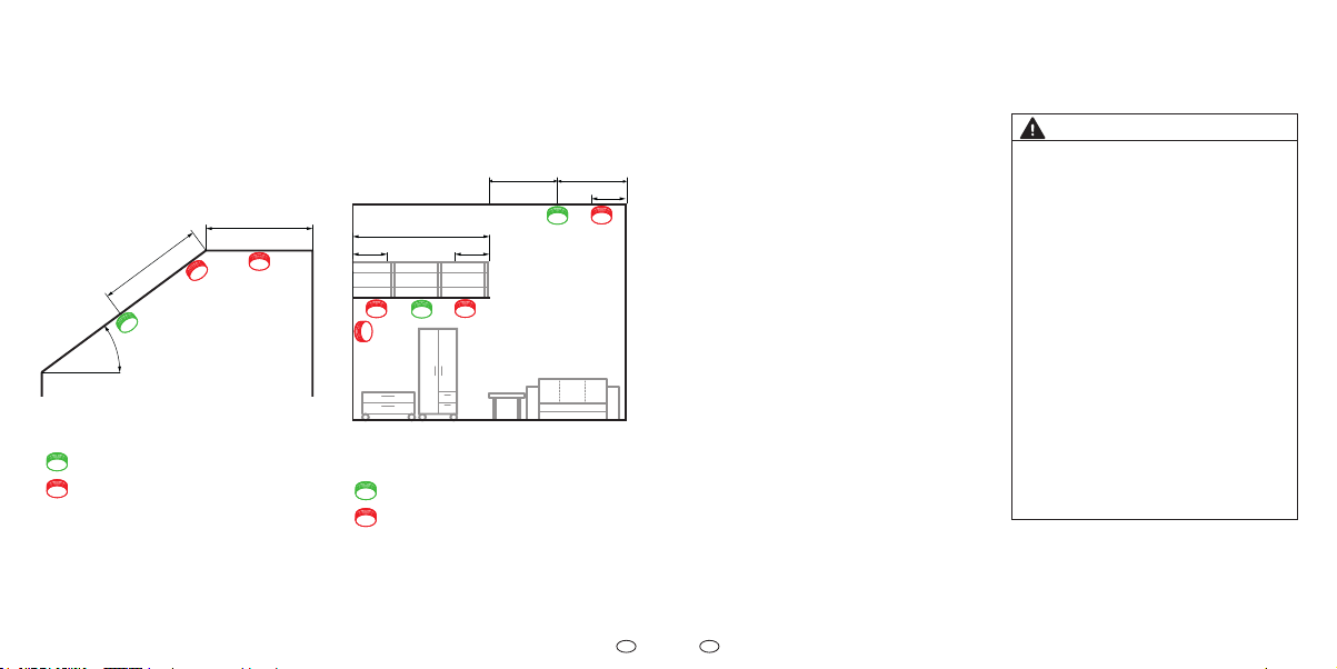
Abb. 4 Räume mit schrägen Raum-
decken
erlaubt
nicht erlaubt
Beachten Sie Folgendes bei der Standortauswahl in Räumen mit schrägen
Raumdecken:
f Geräte mindestens 0,5 m und
höchstens 1 m von der Deckenspitze
entfernt montieren.
18
Betriebsanleitung: XSD200 - Funk-Rauchwarnmelder Betriebsanleitung: XSD200 - Funk-Rauchwarnmelder
4.3 Räume mit schrägen und
waagerechten Raumdecken
> 1,00
1/
> 20°
Abb. 5 Gerade Montageäche mindes-
tens 1 m lang und 1 m breit
erlaubt
nicht erlaubt
Beachten Sie Folgendes, wenn die gera-
de Montageäche mindestens 1 m lang
und 1 m breit ist:
f Kapitel „Räume mit geraden Raum-
decken (Neigungswinkel < 20°)“ auf
Seite 16 beachten.
< 1,00
0,50
>
/2
> 20°
< 1,00
4.4 Räume mit Podest oder
Galerie
0,5
>16 m² / >2 m
0,50,5
Abb. 6 Gerade Montageäche we-
niger als 1 m lang und 1 m breit
erlaubt
nicht erlaubt
Beachten Sie Folgendes, wenn die gerade
Montageäche weniger als 1 m lang und
1 m breit ist:
f Kapitel „Räume mit schrägen Raum-
decken (Neigungswinkel > 20°)“ auf
Seite 17 beachten.
Abb. 7 Räume mit Podest oder
Galerie
erlaubt
nicht erlaubt
Beachten Sie Folgendes für Räume mit
Podesten oder Galerien (Fläche größer
16 m2, mindestens 2 m lang und breit):
f Zusätzliches Gerät unter dem Po-
dest/der Galerie montieren.
19
Page 11
DE
DE
5 Montage
Das Gerät wird von einem Magnetträger am Montageort gehalten.
Der Magnetträger kann durch Kleben oder Bohren montiert werden.
Um Verletzungen durch unsachgemäße
Montage vorzubeugen, sind die Hinweise
in dieser Anleitung zwingend anzuwenden
sowie die allgemeinen Sicherheitsvorschriften zu beachten.
20
Betriebsanleitung: XSD200 - Funk-Rauchwarnmelder Betriebsanleitung: XSD200 - Funk-Rauchwarnmelder
VORSICHT
Mögliche Sachschäden!
Durch das Verwenden eines anderen
Befestigungsmittels (nicht mitgeliefert)
oder durch falsche Voraussetzungen am
Montageort kann das Gerät herunterfallen.
f Bei einer Klebemontage
verwenden Sie ausschließlich das
mitgelieferte Befestigungsmaterial
(Klebepad).
f Bei einer Bohrmontage nutzen
Sie für den jeweiligen Untergrund
geeignete Dübel und Schrauben.
f Stellen Sie sicher, dass
der Montageort ausreichend tragfähig,
fest, trocken, frei von Fett, Staub
und losen Anstrichen etc. ist.
f Beachten Sie, dass der Magnet-
träger nur von einer Seite stark
magnetisch anziehend wirkt.
5.1 Klebemontage
Den Magnetträger können Sie wie folgt
mittels Klebemontage montieren:
• wartungsfreundlich und abnehmbar
nach EN 14604:2005/AC:2008 oder
• wartungsunfreundlich aber
diebstahlsicher nach EN 14604:2005/
AC:2008 und vfdb 14/01 (Q)
Klebemontage nach
EN 14604:2005/AC:2008
Gehen Sie bei dieser Montageart wie
folgt vor:
(1) Magnetträger vom Gerät entfernen
(erst anschließend Splint von Aktivierungstaste entfernen).
f Dazu Magnetträger ankippen.
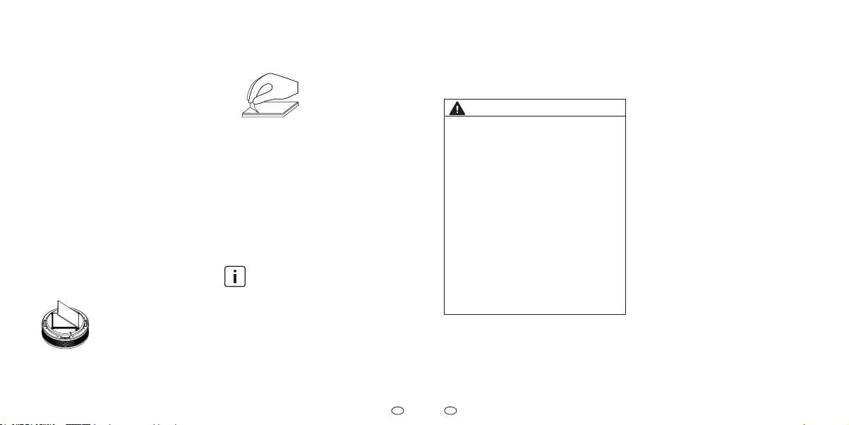
(2) Schutzfolie vom Klebepad auf dem
Magnetträger entfernen.
(3) Magnetträger für ca. 10 Sekun-
den an der Montageposition fest
andrücken.
(4) G
erät in Betrieb nehmen und einrichten.
f Kapitel 6 „Erstinbetriebnahme
und Einrichtung“ auf Seite 24
beachten.
(5) Gerät auf den Magnetträger setzen.
5 Gerät ist auf dem Magnetträger
montiert.
Die Endfestigkeit der Klebeverbindung wird nach ca. 72 Stunden
erreicht.
Klebemontage nach EN 14604:2005/
AC:2008 und vfdb 14/01 (Q)
Um eine dauerhafte Verbindung zwischen
Gerät und Magnetträger herzustellen
(z. B. als Diebstahlschutz), können Sie
mit der zusätzlich mitgelieferten Klebe-
21
Page 12

DE
DE
folie das Gerät auf dem Magnetträger
befestigen.
VORSICHT
Mögliche Sachschäden!
Das Montieren des Gerätes nach
vfdb 14/01 (Q) stellt eine dauerhafte
Verbindung zwischen Magnetträger
und Gerät her. Dadurch wird ein
nachträgliches Abnehmen des
Gerätes verhindert. Die Inbetriebnahme und das Einrichten des Gerätes
sind nicht mehr möglich. Wird das
Gerät demontiert, kann es zu einer
Beschädigung am Gerät und dem
Montageuntergrund kommen.
f Verwenden Sie die zusätzliche
Klebefolie ausschließlich zur
Diebstahlsicherung.
f Nehmen Sie das Gerät vor dem
Befestigen mit der zusätzlichen
Klebefolie in Betrieb und richten
Sie es ein.
22
Betriebsanleitung: XSD200 - Funk-Rauchwarnmelder Betriebsanleitung: XSD200 - Funk-Rauchwarnmelder
Gehen Sie bei dieser Montageart wie
folgt vor:
(1) Magnetträger montieren.
f Kapitel „Klebemontage nach
EN 14604:2005/AC:2008“ auf Seite 21
beachten.
(2) Gerät in Betrieb nehmen und
einrichten.
f Kapitel 6 „Erstinbetriebnahme
und Einrichtung“ auf Seite 24
beachten.
(3) Zusätzliche Klebefolie auf dem
Magnetträgerhalteblech am Gerät
befestigen.
f Schutzfolie auf einer Seite von der
Klebefolie entfernen.
f Klebefolie auf das Magnetträger-
halteblech am Gerät legen und
andrücken.
f Schutzfolie auf der anderen Seite ent-
fernen.
(4) Gerät auf den Magnetträger setzen
und andrücken.
5 Gerät ist auf dem Magnetträger
montiert.
5.2 Bohrmontage
Als Alternative zur Klebemontage können
Sie den Magnetträger auch an den Montageuntergrund anschrauben.
Auch bei der Bohrmontage muss das
Klebepad am Magnetträger verbleiben
und darf nicht entfernt werden.
Gehen Sie bei der Bohrmontage wie folgt
vor:
(1) Magnetträger vom Gerät entfernen.
f Dazu Magnetträger ankippen.
(2) Loch an der Montageposition in den
Montageuntergrund bohren.
(3) Dübel in das Bohrloch einstecken.
(4) Schraube im Magnetträger
andrehen.
(5) Magnetträger über dem Dübel
positionieren.
VORSICHT
Mögliche Sachschäden!
Durch zu festes Anziehen der
Schraube kann sich der Magnetträger
verformen.
f Schrauben Sie die Schraube nur
so tief ein, dass sich der Magnetträger nicht verformt oder wölbt.
(6) Um einen sicheren Halt des Gerätes
zu gewährleisten, Schraube so
tief in den Dübel eindrehen, dass
diese bündig mit dem Magnetträger
abschließt.
Auch bei der Bohrmontage können Sie mit Hilfe der zusätzlichen
Klebefolie eine Klebeverbindung
nach
vfdb 14/01 (Q) herstellen
(siehe Kapitel „Klebemontage
nach EN 14604:2005/AC:2008 und
vfdb 14/01 (Q)“ auf Seite 21).
(7) Gerät in Betrieb nehmen und
einrichten.
f Kapitel 6 „Erstinbetriebnahme
23
Page 13

DE
DE
f
5 keinanderesGerätbendetsichim
und Einrichtung“ auf Seite 24
beachten.
(8) Gerät auf den Magnetträger setzen.
5 Magnetträger ist montiert und das
Gerät aufgesetzt.
Erstinbetriebnahme
6
und Einrichtung
Beachten Sie vor und während der Inbetriebnahme und Einrichtung von Rauchwarnmeldern grundsätzlich Folgendes:
f Geräte einer Funk-Gruppe nachein-
ander an ihrem nalen Montageort
in Betrieb nehmen.
f Um eine Überlagerung von Funk-Si-
gnalen zu vermeiden, einen Mindestabstand von 2 bis 3 m zwischen
den Geräten einhalten.
f Eine Funk-Gruppe aus mindestens
2und maximal 15 miteinander
verbundenen Rauchwarnmeldern
aufbauen.
f Maximal 15 Funk-Gruppen miteinan-
der verbinden.
f Nach der Inbetriebnahme den Splint
als Hilfsmittel zur Betätigung der
Funk-Taste in der Nähe des Gerätes
gribereit aufbewahren.
Gemeinschafts- und Gemeinschafts- und
Neben-Funk-GruppeNeben-Funk-Gruppe
Für spezielle Anwendungen kann es sinnvoll sein, eine Gemeinschafts-Funk-Gruppe einzurichten, z. B. im Flur eines Mehrfamilienhauses. Eine zentrale Funk-Gruppe
(Flur), die mit einer oder mehreren
anderen Funk-Gruppen (Wohnungen)
verbunden wird, übernimmt dabei die
Funktion der Gemeinschafts-Funk-Gruppe
. Die übrigen Funk-Gruppen bilden die
Neben-Funk-Gruppen.
Alarmsignale werden von einer
alarmierten Neben-Funk-Gruppe nur
zur Gemeinschafts-Funk-Gruppe weitergeleitet und lassen diese auslösen. Eine Alarmweiterleitung von der
Gemeinschafts-Funk-Gruppe zur Neben-Funk-Gruppe erfolgt nicht.
f Richten Sie vor dem Verbinden der
einzelnen Funk-Gruppen nacheinander alle Einzelgruppen ein.
Wohnung 1 Wohnung 2Flur
Wohnung 3 Wohnung 4
Abb. 8
ung
cht
larmri
A
Beispiel Gemeinschafts-Funk-Gruppe
Wohnung = Neben-Funk-Gruppe
Flur = Gemeinschafts-Funk-Gruppe
Alarmrichtung = zur Gemeinschafts-FunkGruppe hin
24
Betriebsanleitung: XSD200 - Funk-Rauchwarnmelder Betriebsanleitung: XSD200 - Funk-Rauchwarnmelder
25
Page 14

DE
DE
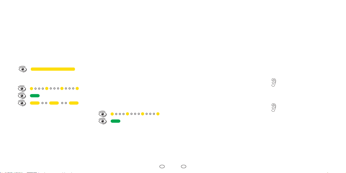
6.1 Funk-Gruppe einrichten
Das zuerst in Betrieb genommene Gerät
ist Master und verwaltet den Aufbau einer
Funk-Gruppe. Beachten Sie beim Einrichten
des Masters einer Funk-Gruppe Folgendes:
(1) Splint seitlich von der Aktivierungs-
taste herunter schieben.
(2) Aktivierungstaste bündig
eindrücken.
kurzer Signalton
5 Kein anderes Gerät bendet sich im
Lernmodus.
(3) Funk-Taste mit Splint drücken und
gedrückt halten, bis Signal-LED
durchgehend leuchtet.
(4) Funk-Taste sofort loslassen, sobald
LED leuchtet.
26
Betriebsanleitung: XSD200 - Funk-Rauchwarnmelder Betriebsanleitung: XSD200 - Funk-Rauchwarnmelder
5 Gerät max. 10 Minuten im Lernmodus.
Um ein weiteres Gerät hinzuzufügen, gehen
Sie wie folgt vor:
(5) Splint seitlich von der Aktivierungs-
taste herunter schieben.
(6) Aktivierungstaste bündig ein-
drücken.Gerät verbindet sich
automatisch.
kurzer Signalton
5 Gerät erfolgreich verbunden.
(7) Um zusätzliche Geräte hinzuzufü-
gen, Schritte (5) und (6) an jedem
weiteren Gerät wiederholen.
Mit jedem neu hinzugefügten Gerät beträgt der Lernmodus erneut
10 Minuten.
6.2 Funk-Gruppe abschließen
Um den Lernmodus einer Funk-Gruppe zu beenden, haben Sie zwei
Möglichkeiten:
f 10 Minuten warten (Lernmodus
endet automatisch) oder
f Funk-Taste an einem beliebigen
Gerät kurz drücken:
Signal-LED „aus“
5 Funk-Gruppe ist in Betrieb.
Signal-LEDs aller
Funk-Gruppen-Teilnehmer
erlischen ebenfalls.
f Zur Überprüfung Verbindungstest
durchführen (siehe Kapitel 9.1 „Verbindungstest der Funk-Gruppe“ auf
Seite 29).
27
Page 15
DE
DE
7
Funk-Gruppe erweitern
und Lernmodus
Eine bestehende Funk-Gruppe können
Sie erweitern, indem Sie die Funk-Gruppe
in den Lernmodus bringen. Beachten Sie
dabei Folgendes:
(1) Funk-Taste mit Splint an einem
beliebigen Gerät drücken und
gedrückt halten.
(2) Funk-Taste loslassen, sobald LED
erlischt.
5 Funk-Gruppe max. 10 Minuten im
Lernmodus.
(3) Um weitere Geräte hinzuzufügen,
siehe Schritte (5) und (6) in
Kapitel 6.1 „Funk-Gruppe einrichten“
auf Seite 26.
28
Betriebsanleitung: XSD200 - Funk-Rauchwarnmelder Betriebsanleitung: XSD200 - Funk-Rauchwarnmelder
8 Gemeinschafts-Funk-
Gruppe einrichte
n
8.1 Funk-Gruppen verbinden
Um Funk-Gruppen miteinander zu verbinden, gehen Sie wie folgt vor:
(1) Gemeinschafts-Funk-Gruppe in den
Lernmodus bringen.
f Siehe Schritte (1) und (2) in Kapitel 7
„Funk-Gruppe erweitern und Lernmodus“ auf Seite 28.
(2) In den zu verbindenden Ne-
ben-Funk-Gruppen das zur Gemeinschafts-Funk-Gruppe nächstgelegene Gerät auswählen.
(3) Am ausgewählten Gerät die
Funk-Taste mit Splint 1 Sekunde
lang drücken.
5 Neben-Funk-Gruppe ist mit der
Gemeinschafts-Funk-Gruppe
verbunden.
(4) Vorgang ggf. bei weiteren Ne-
ben-Funk-Gruppen wiederholen.
(5) Gemeinschafts-Funk-Gruppe
an einem Gerät der Gemeinschafts-Funk-Gruppe abschließen.
f Kapitel 6.2 „Funk-Gruppe abschlie-
ßen“ auf Seite 27 beachten.
5 Gemeinschafts-Funk-Gruppe ist in
Betrieb.
f Zur Überprüfung Verbindungstest
durchführen (siehe Kapitel 9.2
„Verbindungstest zur Gemeinschafts-Funk-Gruppe“ auf Seite
30).
9 Verbindungstest
9.1 Verbindungstest der Funk-
Gruppe
Die korrekte Verbindung einer Gruppe (Funk-Gruppe oder Gemeinschafts-Funk-Gruppe) können Sie wie
folgt testen:
(1) Prüf-/Stopp-Taste eines beliebigen
Gerätes der Gruppe für
ca. 12 Sekunden gedrückt halten.
Nach ca. 1 Sekunde ertönt
der Prüfton.
(2) Nach dem zweiten Prüfton Prüf-/
Stopp-Taste loslassen.
Alle weiteren Geräte der
Funk-Gruppe senden einen
kurzen Prüfton.
5 Erfolgreicher Verbindungstest der
Funk-Gruppe.
Alle innerhalb der Funk-Gruppe verbundenen Geräte senden einen kurzen Signalton. Sollten Geräte defekt sein, bleiben
diese stumm und können so identiziert
werden (siehe
weistöne“ auf Seite 83
Kapitel 17 „Alarm- und Hin-
).
29
Page 16

DE
DE
9.2 Verbindungstest zur
Gemeinschafts-Funk-Gruppe
Die korrekte Verbindung einer Funk-Gruppe zur Gemeinschafts-Funk-Gruppe können Sie nur bei
Geräten einer Neben-Funk-Gruppe wie
folgt testen:
(1) Prüf-/Stopp-Taste eines beliebigen
Gerätes der Neben-Funk-Grup-
pe für ca.24Sekunden gedrückt
halten.
Nach circa 1 Sekunde ertönt
der erste Prüfton. Nach ca.
12 Sekunden der zweite und
nach ca. 24 Sekunden ertönt
ein dritter Prüfton.
(2) Prüf-/Stopp-Taste nach dem dritten
Prüfton (ca. 24 Sekunden) loslassen.
Alle Geräte der Gemeinschafts-Funk-Gruppe und
das Gerät der Hauptgruppe, welches mit der Gemeinschafts-Funk-Gruppe verbunden ist, geben einen kurzen
Prüfton von sich.
(3) Ggf. für weitere Neben-Funk-Grup-
pen wiederholen.
5 5 Erfolgreicher Verbindungstest der
Gemeinschafts-Funk-Gruppe.
Auslieferungszustand
10
wiederherstellen
In den folgenden Situationen müssen Sie den Auslieferungszustand
wiederherstellen:
• Verbindungsversuch war
nicht erfolgreich und muss
wiederholt werden
• um die Zuordnung eines Gerätes zu
einer Funk-Gruppe aufzuheben, z. B. Gerät defekt
Gehen Sie wie folgt vor:
(1) Aktivierungstaste herausziehen.
(2) Prüf-/Stopp-Taste für ca. 2 bis
3Sekunden gedrückt halten, dann
loslassen.
(3) Funk-Taste mit Splint gedrückt halten,
bis die Signal-LED anfängt gelb zu
blinken.
(4) Dann Funk-Taste sofort loslassen.
5 Gerät bendet sich im Ausliefe-
rungszustand.
10.1
Zuordnung eines Gerätes zu
einer Funk-Gruppe aufheben
Die Zuordnung eines Gerätes zu einer Funk-Gruppe
müssen Sie in den folgenden Fällen
aufheben:
• Gerät aus einer bestehenden
Funk-Gruppe entnehmen und in
einer anderen Gruppe neu anlernen
• defektes Gerät aus der
Funk-Gruppe entfernen
In der Funk-Gruppe, aus der das Gerät
entnommen wurde, müssen Sie alle Geräte in den Auslieferungszustand zurück
setzen und neu anlernen:
f Kapitel 6.1 „Funk-Gruppe einrichten“
auf Seite 26 beachten.
f Kapitel 7 „Funk-Gruppe erweitern und
Lernmodus“ auf Seite 28 beachten.
f Kapitel 6.2 „Funk-Gruppe abschlie-
ßen“ auf Seite 27 beachten.
30
Betriebsanleitung: XSD200 - Funk-Rauchwarnmelder Betriebsanleitung: XSD200 - Funk-Rauchwarnmelder
31
Page 17
DE
DE
11 Alarmweiterleitung
und Alarm-Stopp
Die Alarmweiterleitung erfolgt in
zwei Richtungen mit folgenden
Weiterleitungszeiten:
• Alarmweiterleitung innerhalb
einer Funk-Gruppe oder
Gemeinschafts-Funk-Gruppe
= bis zu ca. 20 Sekunden
• Alarmweiterleitung von der
Funk-Gruppe zur GemeinschaftsFunk-Gruppe
Es erfolgt keine Alarmweiterleitung von
der Gemeinschafts-Funk-Gruppe an die
einzelnen Funk-Gruppen.
Repeaterfunktion
Durch die Repeaterfunktion werden
Funk-Signale von einem signalgebenden
Gerät über erreichbare Geräte an nicht
erreichbare Geräte weitergegeben.
Falls Sie Bedarf an bestimmten und/
oder komplexen Verbindungsfunktionen bei der Alarm-Weiterleitung haben, wenden Sie sich an den Hersteller
(siehe Kapitel 15 „Zubehör, Ersatzteile
und Produktsupport“ auf Seite 41).
= bis zu ca. 60 Sekunden
11.1 Alarm-Stopp
Bei einem Alarm mit oder ohne Brandursache können Sie den Alarm stoppen.
Wenn nach einem Alarm-Stopp
weiterhin Brandgefahr besteht,
ertönen die gestoppten Geräte
nach 10 Minuten erneut.
Alarm-Stopp, wenn Alarmweiterleitung
noch nicht stattgefunden hat
Wenn die Alarmweiterleitung noch nicht
stattgefunden hat, können Sie den Alarm
direkt am Alarm auslösenden Gerät
stoppen:
f Prüf-/Stopp-Taste am Alarm auslö-
senden Gerät drücken.
5 Alarm ist gestoppt und wird nicht
weitergeleitet.
Alarm-Stopp, wenn Alarmweiterleitung
bereits stattgefunden hat
Wenn die Alarmweiterleitung in einer
Funk-Gruppe bereits stattgefunden hat
und Sie selbst das Alarm auslösende
Gerät identizieren können, gehen Sie
wie folgt vor:
f Prüf-/Stopp-Taste am Alarm auslö-
senden Gerät drücken.
5 Alarm am auslösenden Gerät
und weiterleitenden Geräten ist
gestoppt.
Wenn die Alarmweiterleitung in einer
Funk-Gruppe bereits stattgefunden hat
und Sie selbst das Alarm auslösende
Gerät nicht identizieren können, gehen
Sie wie folgt vor:
(1) Prüf-/Stopp-Taste an einem Gerät
der Neben-Funk-Gruppe oder Gemeinschafts-Funk-Gruppe drücken.
(2) Alarm der weiterleitenden Geräte
aller verbundenen Gruppen wird
gestoppt
.
Der Alarm des Alarm auslösenden Gerätes kann nur direkt an
dem betreenden Gerät beendet
werden. Dadurch kann im
Brandfall der Brandort lokalisiert
werden.
(3) Prüf-/Stopp-Taste am Alarm auslö-
senden Gerät drücken.
5 Alarm am auslösenden Gerät und
den weiterleitenden Geräten ist
gestoppt.
32
Betriebsanleitung: XSD200 - Funk-Rauchwarnmelder Betriebsanleitung: XSD200 - Funk-Rauchwarnmelder
33
Page 18
DE
DE
12 Stör- und Fehler-
meldungen
Das Gerät prüft automatisch einmal pro
Minute seine Funktionsbereitschaft. Einschränkungen in der Funktion zeigt das
Gerät in Form von Stör- und Fehlermeldungen an. Stellt das Gerät von der Regel
abweichende Umwelteinüsse fest, regelt
es die Empndlichkeit seiner Detektions-
elektronik automatisch nach.
12.1 Störmeldungen
Als Störmeldungen gelten die folgenden
Meldungen:
• Batteriestörungsmeldung
• Kontaminationsmeldung
• Alarm ohne Brandursache
• fehlerhafter Verbindungs-
test Funk-Gruppe
GEFAHR
Gefahr durch Funktionsstörung!
Bei Eintritt der Batteriestörungsmel-
dung/Kontaminationsmeldung kann
der Rauchwarnmelder nur noch für
max. 60 Tage seine zuverlässige
Warnleistung erbringen.
f Ersetzen Sie unbedingt vor Ablauf
der verbleibenden 60 Tage das
Gerät.
Batteriestörungsmeldung
Eine Batteriestörungsmeldung wird
ausgelöst, wenn die Energiereserve des Gerätes angebrochen ist. Während der Batteriestörungsmeldung ertönt alle 90 Sekunden ein einfacher Ton
(siehe Kapitel 17 „Alarm- und Hinweistöne“ auf
Seite 83). Gehen Sie wie folgt vor:
(1) Prüf-/Stopp-Taste drücken, um die
Batteriestörungsmeldung für
24 Stunden zu deaktivieren.
(2) Gerät austauschen.
Kontaminationsmeldung
Eine Kontaminationsmeldung wird ausgelöst, wenn
tektions-Elektronik auf Grund starker Verschmutzung nicht mehr möglich ist.
Während der Kontaminationsmeldung ertönt alle 90 Sekunden ein zweifacher Ton
(siehe Kapitel 17 „Alarm- und Hinweistöne“
auf Seite 83). Gehen Sie wie folgt vor:
(1) Prüf-/Stopp-Taste drücken, um die
die Nachregelung der De-
Kontaminationsmeldung für 24
Stunden zu deaktivieren.
(2) Gerät austauschen.
Alarm ohne Brandursache
Ein Alarm ohne Brandursache wird unter
folgenden Umständen ausgelöst;
• regelmäßige Staubentwicklung
in Wohnräumen mit Textilien, die
eine Staubentwicklung begünstigen (z. B. Teppiche, Kleidung,
Bettdecken und Kopfkissen)
• Blüten-, Bau-, Schleif-
oder Feinstaub
• Insekten bzw. Kleinstorganismen,
die die Insektenschutzbarrieren
des Gerätes überwunden haben
• starke Koch-, Wasser- und/oder
Bratendämpfe sowie Raum-,
Duft- und Insektenspray
•
extreme Temperaturschwankungen
oder sehr starke elektromagnetische Strahlung wirken in direkter
Umgebung auf das Gerät ein
34
Betriebsanleitung: XSD200 - Funk-Rauchwarnmelder Betriebsanleitung: XSD200 - Funk-Rauchwarnmelder
35
Page 19

DE
DE
Zigarettenrauch löst nur in unmittelbarer Nähe und hoher
Konzentration einen Alarm aus.
Folgende Abhilfemaßnahmen können
Sie treen:
f Alarm stoppen (siehe Kapitel 11.1
„Alarm-Stopp“ auf Seite 32).
f Auf eine ausreichende Belüftung
des Montageortes achten.
f Gerät vorsichtig und regelmäßig
reinigen, z. B. mit einem Staubsauger.
f Nachbarn über einen Alarm ohne
Brandursache informieren, damit
nicht fälschlicher Weise die Feuerwehr alarmiert wird.
12.2 Problembehandlung
Probleme können während der Inbetriebnahme, Einrichtung und dem Betrieb unter
folgenden Umständen auftreten:
• Geräte nicht oder nicht
mehr im Lernmodus
• Funk-Gruppe nicht oder nicht
mehr im Lernmodus
36
Betriebsanleitung: XSD200 - Funk-Rauchwarnmelder Betriebsanleitung: XSD200 - Funk-Rauchwarnmelder
• keine Funk-Verbindung, obwohl Ge-
rät und Funk-Gruppe im Lernmodus
• defektes Gerät in einer Funk-Gruppe
Ein Problem erkennen Sie am Lichtsignal der Signal-LED (siehe
Kapitel 18 „Lichtsignale“ auf Seite 87).
Gerät nicht oder nicht
mehr im Lernmodus
Wenn ein Gerät nicht mit einer Funk-Gruppe verbunden werden kann und dessen
Signal-LED nicht gelb blinkt, kann es sein,
dass sich das Gerät nicht oder nicht mehr
im Lernmodus bendet. Gehen Sie für die
Problembehandlung wie folgt vor:
(1) Aktivierungstaste nach oben ziehen.
(2) Prüf-/Stopp-Taste 2 bis 3 Sekunden
lang drücken.
(3) Gerät in den Lernmodus bringen
(siehe Kapitel 7 „Funk-Gruppe erweitern
und Lernmodus“ auf Seite 28).
(4) Ggf. Gerät in den Auslieferungs-
zustand bringen (siehe Kapitel 10
„Auslieferungszustand wiederherstellen“ auf Seite 31).
(5) Funk-Gruppe erweitern (siehe Ka-
pitel 7 „Funk-Gruppe erweitern und
Lernmodus“ auf Seite 28).
Funk-Gruppe nicht oder nicht
mehr im Lernmodus
Wenn ein Gerät nicht mit einer Funk-Gruppe verbunden werden kann und die Signal-LEDs der Geräte der Funk-Gruppe
nicht gelb blinken, kann es sein, dass die
Funk-Gruppe nicht oder nicht mehr im
Lernmodus ist. Gehen Sie für die Problem
behandlung wie folgt vor:
f Funk-Gruppe in den Lernmo-
dus bringen (siehe Kapitel 7
„Funk-Gruppe erweitern und Lernmodus“ auf Seite 28).
Gerät und Funk-Gruppe im Lernmodus
Auch wenn sich Gerät und Funk-Gruppe im Lernmodus befinden und die
Signal-LED gelb blinkt, kann es sein,
dass keine Funk-Verbindung besteht.
Gehen Sie für die Problembehandlung
wie folgt vor:
(1) Abstand zwischen den Geräten
prüfen, ggf. Abstand verringern.
(2) Geräte und Funk-Gruppe neu in
Betrieb nehmen.
f Auslieferungszustand aller Geräte
wiederherstellen (siehe Kapitel 10
„Auslieferungszustand wiederherstellen“ auf Seite 31).
f Geräte und Funk-Gruppe neu in Betrieb
nehmen (siehe Kapitel 6 „Erstinbetriebnahme und Einrichtung“ auf Seite
24).
-
Fehlerhafter Verbindungstest
Funk-Gruppe
Ein defektes Gerät kann innerhalb einer
Funk-Gruppe durch den „Verbindungstest
Gruppe“ (siehe Kapitel 9.1 „Verbindungstest der Funk-Gruppe“ auf Seite 29)
identifiziert werden. Wurde ein defektes
Gerät identiziert, gehen Sie für die Problembehandlung wie folgt vor:
f Um eine temporäre Funk-Störung
durch andere Funk basierende Ge-
37
Page 20

DE
DE
13 Instandhaltung
räte auszuschließen, Verbindungstest Gruppe an einem anderen
Gerät erneut durchführen.
5 Verbindungstest war erfolgreich
und alle Geräte sind funktionsfähig.
oder
5 Verbindungstest war nicht erfolg-
reich, es bendet sich ein defektes
Gerät in der Funk-Gruppe.
(1) Defektes Gerät in den Ausliefe-
rungszustand zurück setzen (siehe
Kapitel 10 „Auslieferungszustand
wiederherstellen“ auf Seite 31).
(2) Zuordnung des defekten Gerätes
zur Funk-Gruppe aufheben (siehe
Kapitel 10.1 „Zuordnung eines Gerätes zu einer Funk-Gruppe aufheben“
auf Seite 31).
(3) Funk-Gruppe mit reduzierter Anzahl
an Geräten neu anlernen (siehe
Kapitel 10.1 „Zuordnung eines Gerätes zu einer Funk-Gruppe aufheben“
auf Seite 31).
38
Betriebsanleitung: XSD200 - Funk-Rauchwarnmelder Betriebsanleitung: XSD200 - Funk-Rauchwarnmelder
Um ein Ersatzgerät zur Funk-Gruppe hinzuzufügen, beachten Sie die folgenden
Kapitel:
• Kapitel 7 „Funk-Gruppe erweitern
und Lernmodus“ auf Seite 28.
• Kapitel 6.2 „Funk-Gruppe
abschließen“ auf Seite 27.
13.1 Wartung
In regelmäßigen Abständen müssen
Sie Sicht- und Funktionsprüfungen
durchführen.
Sichtprüfung
Führen Sie einmal im Jahr eine Sichtprüfung durch:
f Darauf achten, dass die Rauchein-
lasslamellen nicht zugesetzt sind
(z. B. durch Staub, Schmutz, Farbe).
f Darauf achten, dass das Gerät un-
beschädigt und fest am Einsatzort
montiert ist.
Funktionsprüfung
Da es sich bei Rauchwarnmeldern um
elektronische Geräte handelt, lösen Sie
regelmäßig, mindestens einmal im Jahr,
einen Prüfton aus:
f Wenn kein Prüfton ertönt, müssen
Sie das Gerät austauschen.
Prüfton Gerät
Lösen Sie regelmäßig, mindestens einmal
im Jahr, einen Prüfton aus:
f Prüf-/Stopp-Taste für ca. 2 bis
3 Sekunden drücken.
kurzer Prüfton, Einzelgerät
Wenn Sie den Probealarm innerhalb von weniger als 10 Minuten
wiederholen, ertönt bei bestimmten Gerätevarianten ein zweifacher, kurzer Prüfton.
Prüfton Funk-Gruppe
Lösen Sie regelmäßig, mindestens einmal
im Jahr, einen Prüfton aus:
f Kapitel 9.1 „Verbindungstest der
Funk-Gruppe“ auf Seite 29 beachten.
f Bei einem defekten Gerät Kapitel „Feh-
lerhafter Verbindungstest Funk-Gruppe“ auf Seite 37 beachten.
Prüfton zur Gemeinschafts-Funk-Gruppe
Lösen Sie regelmäßig, mindestens einmal
im Jahr, einen Prüfton aus:
f Kapitel 9.2 „Verbindungstest zur
Gemeinschafts-Funk-Gruppe“ auf
Seite 30 beachten.
39
Page 21
DE
DE
die Aktivierungstaste heraus
1
13.2 Reinigung
Führen Sie die Reinigung mindestens einmal im Jahr durch. Beachten Sie Folgendes bei der Reinigung:
f Gerät vom Magnetträger abneh-
men.
f Vorsichtig reinigen, z. B. mit einem
Staubsauger und feuchtem Tuch.
f Führen Sie nach der Reinigung
eine Funktionsprüfung durch, siehe
Abschnitt 13 Instandhaltung, Funktionsprüfung.
13.3 Wartungsdokumentation
Die PyrexxGmbH behält sich vor, zum
Prüfen von etwaigen Garantieansprüchen, einen Nachweis über die jährlich
vorgeschriebene Wartung anzufordern.
Eine Möglichkeit die Wartung gemäß
DIN14676 zu dokumentieren bietet Ihnen
die kostenlose Pyrexx Web-App.
Die Pyrexx Web-App steht Ihnen unter
pyrexx.com/app zur Verfügung und gibt
Ihnen die Möglichkeit, die jährlichen Prüfund Wartungsleistungen Ihrer Rauchwarnmelder zu erfassen.
40
Betriebsanleitung: XSD200 - Funk-Rauchwarnmelder Betriebsanleitung: XSD200 - Funk-Rauchwarnmelder
14 Außerbetriebnahme
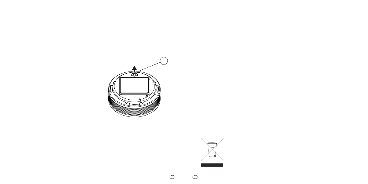
14.1 Deaktivierung des Gerätes
f Ziehen Sie zum Deaktivieren des
Gerätes die Aktivierungstaste
heraus.
Abb. 9 Aktivierungstaste herauszie-
hen
1 Aktivierungstaste
14.2 Endgültige
Außerbetriebnahme
Der Rauchwarnmelder hat nach spätestens 12 Jahren seine bestimmungsgemäße und zugleich maximale Nutzungsdau-
er erreicht.
f Tauschen Sie das Gerät mit Ablauf
dieser Nutzungsdauer aus.
14.3 Entsorgung
Dieses Produkt darf gemäß ElektroG
nicht in den Hausmüll gelangen.
f S
enden Sie das zu entsorgende
Gerät an den Hersteller zur weiteren
Verwertung, geben es bei Ihrem regionalen Entsorgungsunternehmen oder
den eingerichteten Rücknahmestellen
der Hersteller ab. Ein Onlineverzeich-
nis der Rücknahmestellen nden Sie
unter:
ear-system.de/ear-verzeichnis/sammel-und-ruecknahmestellen.jsf
f Beachten Sie, dass durch nicht
ordnungsgemäße Entsorgung die
Umwelt geschädigt werden kann.
15 Zubehör, Ersatzteile
und Produktsupport
15.1 XSD200 Zubehör
• PX-iP Gateway für XSD200
Funknetzwerke
• Pyrexx Montagestab mit
Krallenkrone (für Dienstleister)
• RWM MC (Diagnosegerät)
für einen erweiterten Funktionstest (für Dienstleister)
• PX-AR Alarmrelais
15.2 XSD200 Ersatzteile
• Abdeckung Rauchwarn-
melder (Dekodeckel)
• Magnetträger mit Klebepad
• Klebefolie
• Splint (Aktivierungssicherung)
41
Page 22

EN
DE
15.3 Produktsupport
Im Garantie- bzw. Gewährleistungsfall
übersenden Sie das Gerät bitte an den
Verkäufer.
Der Produktsupport ist per E-Mail
unter support@pyrexx.com und te-
lefonisch unter +49 30 74 74 74 75 zu
erreichen.
Erklärende Filme zu unseren Produkten
nden Sie auf pyrexx.com/de/support/
mediathek.
42
Betriebsanleitung: XSD200 - Funk-Rauchwarnmelder
1 Notes on the
operating manual
We are glad that you have chosen our
product and we would like to thank you
for your trust!
This operating manual contains information and instructions for safe assembly,
activation, installation and maintenance,
as well as proper operation of the smoke
alarm device with radio link.
The operating manual is intended to increase the reliability and life cycle, and
to help avoid hazards and downtime, or
a loss of warranty claims.
It is absolutely necessary that the operating manual is read and understood.
For a better readability, the XSD200
smoke alarm device with radio link is
hereinafter referred to as “smoke alarm
device” or “device”.
1.1 Scope of the operating
manual
The operating manual applies only to the
smoke alarm device with radio link of the
XSD200 type.
Operating Manual: XSD200 - Smoke Alarm Device with Radio Link
1.2 Name plate and
identication
The name plate of the smoke alarm de-
vice is located below the testing/stop
button (smoke alarm device cover).
Smoke alarm device with "Q" label
A smoke alarm device with “Q” label has a
on the name plate.
1.3 Conformity
The XSD200 smoke alarm device with “Q”
label is certied according to:
• vfdb guideline 14/01 (Q)
• 2014/53/EU (RED)
• Regulation (EU) No 305/2011
according to EN14604:2005/AC:2008
21
1772-CPR-210050
Variante: V3-Q
For more information about the “Q”
label and the vfdb guideline, please visit
our website at pyrexx.com.
43
Page 23

EN
EN
Conformity according to
2014/53/EU (RED)
Pyrexx GmbH declares that the smoke
alarm device is compliant with the fundamental requirements and other relevant
provisions of the 2014/53/EU Directive.
The Declaration of Conformity is availa-
ble at the following address:
pyrexx.com/en/support/downloads
Conformity in accordance with
EN 14604:2005/AC:2008 (CE)
The smoke alarm device is certied as
a construction product in accordance
with Directive (EU) No. 305/2011 according to EN14604:2005/AC:2008 (CE). The
production is monitored for unchanged
compliance with legal and normative
requirements by periodic and independent checks.
The Declaration of Performance for a
smoke alarm device without “Q” label is
available at the following reference num-
ber at the manufacturer: k_95531
The De
claration of Performance for a
smoke alarm device with “Q” label is
available at the following reference num-
44
Operating Manual: XSD200 - Smoke Alarm Device with Radio Link Operating Manual: XSD200 - Smoke Alarm Device with Radio Link
ber at the manufacturer: k_503413
1.4 Safekeeping of the
operatingmanual
The operating manual is an important
component of the smoke alarm device,
and must always be kept at hand near
the installation location.
1.5 Symbols used
Various markings and symbols are used
in the text in the operating manual.
These are explained below.
Warning symbol in warning labels
Additional information and
guidelines
(1) Numbered action steps
f Symbol for an instruction or a
required action
5 Result of an action
• Symbol for a list
1.6 Copyright
All rights are reserved, particularly the
rights of duplication, distribution and
translation. No part of this operating
manual may be reproduced in any form,
or processed, duplicated, or disseminated
using electronic systems without written
permission of Pyrexx GmbH.
1.7 Guarantee and warranty
The Pyrexx guarantee conditions and
the statutory warranty apply. The
PyrexxGmbH warrants a defect-free
device only for the original purchaser of
this product that was purchased either at
PyrexxGmbH directly, or through an authorized reseller, for a period of 12years
from the date of purchase, when used
and serviced as intended. Thereby the
limited warranty covers the entire de-
vice for 10years. For the remaining
twoyears, the limited warranty shall not
extend to the reserve/ power supply to
the electronics of the device, whereas
the material/workmanship errors are
exempt from this restriction.
You can nd the Pyrexx guarantee conditions at pyrexx.com/en/support/down-
loads in the download area.
45
Page 24

EN
EN
2 Safety instructions
2.1 Representation and
structure of warning labels
The warning labels are action-oriented;
they are structured and graded as follows:
DANGER
Type and source of the danger!
Explanation about the type and
source.
f Measures to avert the danger.
DANGER
Imminent mortal danger or serious
injury.
CAUTION
Potential minor injuries, property or
environmental damage.
46
Operating Manual: XSD200 - Smoke Alarm Device with Radio Link Operating Manual: XSD200 - Smoke Alarm Device with Radio Link
2.2 Intended use
The device may only be used for the following purposes:
• Smoke detection and heat
warning in private households and
residential real estate including
alarm forwarding via radio link
• Smoke alarm device indoors
• Radio group or shared radio
group of smoke alarm devices
• Use in leisure accommodation
vehicles (e.g. caravans)
• Use in accordance with DIN14676
and applicable construction
ordinances, construction regulations
and re protection regulations
Note the following when using the smoke
alarm device:
f Use the device only as intended and
in a technically perfect condition.
f For special settings, contact the
manufacturer.
2.3 Unintended use
The device must not be used for the following purposes:
• Heat detection in terms of EN 54-5
• Wireless smoke detection/re
detection in terms of EN 54-25
• Any use that is not expressly
described as permitted in
this operating manual
2.4 Maximum useful life
The smoke alarm device will reach
the end of its useful life at the latest after 12 years of usage according to the intended purpose. The 12
years mentioned here are divided into a typical service life of
10 years, and in a service life/power reserve of up to a further 2 years.
f Replace the device at the end of
this useful life.
2.5 Basic safety instructions
The basic safety instructions group all
the safety measures by topic and apply
at all times.
General informationGeneral information
Smoke alarm devices provide early
warning of smoke or re, so that the residents of the house and the apartment
are able to react on time, in particular, to
leave the premises immediately and to
alert the re brigade. Smoke alarm devices do not prevent res, nor do they ght
res automatically. Smoke alarm devices do not directly alert the re brigade
or other emergency services. Smoke
alarm devices are not used to prevent
fire damage, particularly if no one is
present when the fire breaks out. The
smoke alarm devices are subject to strict
quality controls during manufacture.
In addition, a function test is performed
before delivery. Nevertheless, unexpected malfunctions may occur
.
47
Page 25

EN
EN
•
•
•
•
•
What to do if there is a re?
(1) Keep calm.
(2) Warn all co-residents.
(3) Help children, disabled, elderly and
sick people.
(4) Close all windows and doors behind
you.
(5) Leave the house immediately.
(6) Do not use lifts.
(7) Alert the re brigade. 112
Battery replacement
A battery change is not necessary and
is technically impossible, as the device
must not be opened.
External inuencesExternal inuences
External inuences can cause malfunction and damage to the device and the
battery.
48
Operating Manual: XSD200 - Smoke Alarm Device with Radio Link Operating Manual: XSD200 - Smoke Alarm Device with Radio Link
Protect the device from:
• Moisture
• Cold
• Direct sunlight or excessive heat
(damage to the battery)
• Dust and particulate matter
• Spiders and insect infestation
• Grease
• Nicotine and paint fumes
• Coatings (e.g., wall paint)
• Adhesives
• Dirt of any kind
Immersion in water
Immersion in water will cause damage
to the device.
f Do not immerse the device in water.
Opening the deviceOpening the device
The device is a closed system. Any tampering with the device, in addition to the
loss of the limited warranty and statutory
warranties, also means that the device
must not be used as intended.
f Do not open the device.
As an exception, you may remove the
decoration cover (cover of the smoke
alarm device) to identify the device or
for decorating.
Sensitive componentsSensitive components
The device consists of sensitive components (e.g. sensors)
.
f Do not throw the device.
f Do not drop the device.
f Do not apply pressure to the device.
Decorating
If the smoke intake lamellas are covered,
the smoke detection and heat warning
functions can be impaired or prevented.
No reliable alarm can be triggered.
f Only decorate the decoration cover
(cover of the smoke alarm device)
and keep the smoke intake lamellas
free.
49
Page 26
EN
EN
3 Overview
Renovation workRenovation work
During renovation, construction and
sanding work, malfunction or damage
to the device may occur due to the development of dust.
f Remove the device prior to reno-
vations, or protect it with a suitable
cover.
No reliable alarm can be
triggered while the device is
covered.
f Mount the device after completion
of the renovation work on the
original usage location, or remove
the cover
50
.
Operating Manual: XSD200 - Smoke Alarm Device with Radio Link Operating Manual: XSD200 - Smoke Alarm Device with Radio Link
3.1 Function
The basic functions of the device are:
• Smoke detection based on the
optical detection method
• Heat warning function
• Connect a maximum of
15devices into a radio group
• Connect a maximum of 15radio
groups with another (including
shared radio group)
• Alarm forwarding to all
devices in a radio group
• Alarm forwarding from a radio
group to shared radio group
• Repeater function
If you need specic, complex and
possibly cascading connection
functions for the alarm
forwarding, please contact the
manufacturer (see chapter 15
“Accessories, spare parts and
product support“ on page 79).
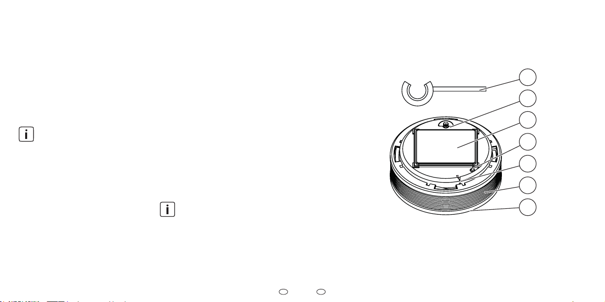
3.2 Components
Fig. 10 Components
1 Splint pin (activation backup)
2 Activation button
3 Magnet carrier
1
2
3
4
5
6
7
4 Signal LED
5 Radio button
6 Smoke intake lamellas
7 Testing/stop button
(smoke alarm device cover)
51
Page 27
EN
EN
4 Location selection
Splint pin (activation backup)
The splint pin (activation backup) is used
during the transport of the device to protect against accidental activation.
After activating the device, the splint pin
(activation backup) is used as a tool for
operating the radio button, and must be
kept readily available in the vicinity of
the device.
Activation button
The activation button is used to turn the
device on and o.
Magnet carrier
The magnet carrier is used for fastening
the device.
Signal LED
The signal LED displays results and intermediate results during start-up of devices and setting up of radio groups or
shared radio groups.
52
Operating Manual: XSD200 - Smoke Alarm Device with Radio Link Operating Manual: XSD200 - Smoke Alarm Device with Radio Link
Radio button
The radio button is found in the opening
marked with an arrow. It is used to set up
the radio connection between devices.
Smoke intake lamellas
Smoke from the re reaches the inside
of the device through the smoke intake
lamellas and can then be detected by
sensors.
Testing/stop button
(smoke alarm device cover)
The testing/stop button (smoke alarm
device cover) is used for a self-test, for
correct wireless connection between
multiple devices or between devices of
a radio group.
The testing/stop button (smoke alarm
device cover) can be pressed to interrupt
or stop alarm and alert tones.
Attic
Top
Guest room
floor
Upper
Bedroom
floor
Ground
Livingroom
floor
Cellar
*
Heating
Fig. 11 Location selection
Oce
Children´s
bedroom
Kitchen
Workroom
Minimum equipment
Optimal equipment
*
Required by law in Berlin
and Brandenburg
Conditional
Do not install due t o
steam
Escape route
Corridor
Bath-
room
Children´s
Bedroom
Kitchen
Livingroom
*
53
Bedroom
Children´s
*
Bedroom
Page 28

EN
EN
The use of smoke alarm devices is governed by DIN 14676.
Minimum equipment
• Bedrooms
• Children’s bedroom
• Guest room
• Hallways and all other rooms
which serve as an escape route
• Stairwells of family houses
Optimal equipment
• All living and hobby rooms (except in
Berlin and Brandenburg - here such
equipment is also required by law)
• Heating and work spaces
• Oce or workroom
• Cellar
• Attic
Conditional equipment
• I
n kitchens, smoke alarm devices must
only be installed if false alarms
(e.g. caused by steam)
can be excluded.
54
Operating Manual: XSD200 - Smoke Alarm Device with Radio Link Operating Manual: XSD200 - Smoke Alarm Device with Radio Link
Not recommended
• Bathrooms are excluded
from the installation
of smoke
alarm devices due to the high
development of steam.
4.1 Area to be monitored
Use a device if at least one of the following applies:
• Monitoring area less than 60m²
and room height less than 6m
• Ceiling panels (height lower than
20cm) with joists (area of ceiling
panels less than 36 m2)
Use additional devices if at least one of
the following applies:
• Monitoring area greater than 60 m
• Ceiling height greater than 6 m
• High partial walls
• Separating pieces of furniture
• Ceiling panels (height greater
than 20cm) with joists (area of
ceiling panels larger than 36m²)
• Platform/gallery (area greater than
16m2, at least 2 m long and wide)
In rooms with beams (e.g.,
wooden beams), the number
and arrangement of the devices
depends on the height of the joists
and the surface formed by the
beams.
4.2 Requirements for the
monitoring area
When selecting the appropriate monitoring area, observe the following:
f Position the device centrally on the
ceiling.
f Position the master or shared radio
group at a central location
2
(e.g. in the corridor).
f If possible, maintain an approxi-
mately equal distance between the
master and all other devices in a
radio group.
f Maintain an approximately equal
distance between the shared radio
group and other radio groups
.
f If necessary, install additional
f Keep a minimum distance of 2m
to electronic, radio-based devices
(e.g.Wi-Fi router).
f Keep a minimum distance of 3m
to other smoke alarm device with
radio link.
f Observe the maximum installation
height of 6 m.
f Keep a minimum distance of 0.5m
to surrounding walls, furniture and
lamps.
f Keep a maximum distance of 6m
to a potential re source.
Areas susceptible to draughtsAreas susceptible to draughts
For occurring smoke to be able to reach
the smoke alarm device, there must
not be any strong draughty inuences
around the installation site (e.g. caused
by air conditioning systems or ventilation intakes or fans). In rooms with forced
ventilation, perforated ceilings which
are used for ventilation must be closed
o within a radius of 0.5m around the
alarm device
.
devices.
55
Page 29
EN
EN
50
1/21/2
f
corridor)andtherstdevice.
f
f
Stirnäche(EndedesFlures)unddem
f
f
f
21
f
Stirnäche(EndedesFlures)unddem
f
f
f
f
entering the smoke alarm device.
f
f
Stirnäche(EndedesFlures)unddem
f
f
Rooms with straight ceilings
(slope angle < 20°)
0,
Rooms with straight ceilings
Fig. 12 Rooms with straight ceilings
Allowed
Not allowed
Note the following for locations in rooms
with straight ceilings:
f Select the highest mounting point
on the ceilings.
f Mount the devices horizontally to
the mounting surface.
56
Operating Manual: XSD200 - Smoke Alarm Device with Radio Link Operating Manual: XSD200 - Smoke Alarm Device with Radio Link
Narrow spaces or corridors
(1-3 m wide)
In addition, observe the following for locations in narrow rooms or corridors that
,50,5
are 1-3m wide
f Keep a distance of less than 7.5 m
between the front surface (end of
the corridor) and the rst device.
f Keep a distance of less than 15m
between 2 devices.
Narrow spaces or corridors
(< 1 m wide)
In addition, observe the following for locations in narrow rooms or corridors that
are less than 1 m wide:
f Keep a distance from surrounding
walls (exception: distance less than
0.5m).
Rooms with slanted ceilings
(slope angle > 20°)
In rooms with ceiling slope angles of
more than 20° to the horizontal, heat
:
build-ups can occur in the ceiling peak
which stop smoke entering the smoke
alarm device.
> 0,50
< 1,00
> 20°
Fig. 13 Rooms with slanted ceilings
Allowed
Not allowed
Note the following for location selection
in rooms with slanted ceilings:
f Mount devices at least 0.5m and at
most 1m from the ceiling peak.
4.3 Rooms with slanted and
horizontal ceilings
> 1,00
1/
/2
> 20°
Fig. 14 Straight mounting surface at
least 1 m long and 1 m wide
Allowed
Not allowed
57
Page 30
EN
EN
f
Stirnäche(EndedesFlures)unddem
f
f
f
page
53.
f
Stirnäche(EndedesFlures)unddem
f
f
5 Installation
Note the following for straight mounting
surface less than 1m long and 1m wide:
f Observe chapter “Rooms with
straight ceilings (slope angle < 20°)“
on page <ÜS>).
> 0,50
< 1,00
> 20°
Fig. 15 Straight mounting surface less
than 1 m long and 1 m wide
Allowed
Not allowed
Note the following for straight mounting
surface less than 1 m long and 1 m wide:
f Obser ve chapter “Rooms with
slanted ceilings (slope angle > 20°)“
on page 56).
58
Operating Manual: XSD200 - Smoke Alarm Device with Radio Link Operating Manual: XSD200 - Smoke Alarm Device with Radio Link
< 1,00
4.4 Rooms with a platform or
gallery
1/2
>16 m² / >2 m
0,50,5
Fig. 16 Rooms with a platform or
gallery
Allowed
Not allowed
Note the following for rooms with platforms or galleries (area greater than
16m², at least 2m long and wide):
f Mount an additional device under
the platform/gallery.
The device is held by a magnet carrier at
the installation location. The magnet car-
1/2
0,5
rier can be mounted by gluing or drilling.
To avoid injuries from improper
installation, the instructions in this manual must be followed. The general safety regulations should also be observed.
CAUTION
Possible property damage!
Using other fastening material (not
enclosed) or wrong conditions at the
installation location can cause the
device to fall down.
f For adhesive mounting, use only
the supplied mounting material
(adhesive pad).
f For drill mounting, use screws
and dowels that are suitable for
the respective surface.
f Ensure that the installation
location is strong enough, solid,
dry, free from grease, dust and
loose paint etc.
f Note that the magnet carrier
magnetically attracts only from
one side.
59
Page 31
EN
EN
5.1 Adhesive mounting
The magnet carrier can be mounted using adhesive assembly as follows:
• Easy to maintain and removable ac-
cording to EN 14604:2005/AC:2008 or
• maintenance-unfriendly but theft-
proof according to
EN 14604:2005/AC:2008
and vfdb 14/01 (Q)
Adhesive mounting according to
EN 14604:2005/AC:2008
When performing this type of installation,
proceed as follows:
(1) Remove magnet carrier from the
device. (Remove the splint from the
activation button only after that.)
f To do this, tilt the magnet carrier.
(2) Remove the protective lm from the
adhesive pad on the magnet carrier.
60
Operating Manual: XSD200 - Smoke Alarm Device with Radio Link Operating Manual: XSD200 - Smoke Alarm Device with Radio Link
(3) Press the magnet carrier rmly for
about 10 seconds at the mounting
position.
(4) Activate the device and set it up.
f Obser ve chapter 6 “Initial activation
and setting up“ on page 63.
(5) Position the device on the magnet
carrier.
5 The device is mounted on the
magnet carrier.
The ultimate strength of the adhesive bond is achieved after about
72 hours.
Adhesive mounting according to EN
14604:2005/AC:2008 and vfdb 14/01
(Q)
To establish a permanent connection
between the device and magnet carrier
(e.g., as theft protection), you can addi-
tionally mount the device with the sup-
plied adhesive lm on the magnet carrier.
CAUTION
Possible property damage!
Mounting the device in accordance
with vfdb 14/01 (Q) establishes a
permanent connection between
magnet carrier and the device. Thus,
a subsequent removal of the device
is prevented. The start-up and set up
of the device are no longer possible.
If the device is disassembled, it can
cause damage to the device and the
mounting surface
.
f Use the additional adhesive lm
only to prevent theft.
f Activate the device and set it up
before attaching the additional
adhesive lm.
When performing this type of installation,
proceed as follows:
(1) Mount the magnet carrier.
f Observe chapter “Adhesive mounting
according to EN 14604:2005/AC:2008“ on
page 60.
(2) Activate the device and set it up.
f Obser ve chapter 6 “Initial activation
and setting up“ on page 63.
(3) Attach the additional adhesive lm
to the magnet carrier sheet plate on
the device
.
f Remove the protective lm from
one side of the adhesive lm.
f Place the adhesive lm on the mag-
net carrier sheet plate on the device
and press it on.
f Remove the protective lm on the
other side.
(4) Place the device on the magnet
carrier and press it on.
5 The device is mounted on the mag-
net carrier.
61
Page 32

EN
EN
5.2 Drilling installation
As an alternative to adhesive mounting,
you can also screw the magnet carrier
on the mounting surface.
Even with the drilling installation, the adhesive pad must remain on the magnet
carrier and must not be removed.
When performing the drilling installation,
proceed as follows:
(1) Remove the magnet carrier from
the device.
f To do this, tilt the magnet carrier.
(2) Drill a hole on the mounting position
in the mounting surface.
(3) Insert a dowel into the drilled hole.
(4) Tighten the screw in the magnet
carrier.
(5) Position the magnet carrier over
the dowel.
CAUTION
Possible property damage!
Over-tightening the screw may
deform the magnet carrier.
f Tighten the screw only so deep
that the magnet carrier is not
deformed or bulged.
(6) To ensure a safe hold of the device,
tighten the screw deep into the
dowel so that it closes ush with the
magnet carrier
Also in a drilling installation, you
can create an adhesive compound using additional adhesive
lm, according to
(see chapter “Adhesive mount-
ing according to EN 14604:2005/
AC:2008 and vfdb 14/01 (Q)“ on
page 60).
.
vfdb 14/01 (Q)
(7) Activate the device and set it up.
f Obser ve chapter 6 “Initial activation
and setting up“ on page 63.
(8) Position the device on the magnet
carrier
.
5 The magnet carrier is attached and
the device positioned on it.
Initial activation and
6
setting up
Always consider the following when
activating and setting up smoke alarm
devices
:
f Activate devices in a radio group
one after another in their nal
installation location.
f To prevent overlaying radio signals,
keep a minimum distance of 2 to
3m between the devices.
f Establish a radio group of at least 2
and a maximum of 15 smoke alarm
devices connected together.
f Connect a maximum of 15 radio
groups together.
f After activating the device, the
splint pin is used as a tool for triggering the radio button, and must
be kept readily available in the
vicinity of the device.
62
Operating Manual: XSD200 - Smoke Alarm Device with Radio Link Operating Manual: XSD200 - Smoke Alarm Device with Radio Link
63
Page 33

EN
EN
Ther stdeviceplacedinto ser vice isMaster,
Pushactivationbuttonush.
5
f
Shared radio group and subgroupShared radio group and subgroup
For special applications, it may be useful to set up a shared radio group e.g.,
in the corridor of an apartment building.
A central radio group (corridor) which is
associated with one or more other radio
groups (at) thereby takes over the function of the shared radio group. The other
radio groups form subgroups.
Alarm signals are passed only to the
shared radio group from an alarming
subgroup and trigger it. Alarm forwarding from the shared radio group to the
subgroup does not occur.
f Set up all individual groups before
connecting the radio groups.
f First set up every individual group
and then connect them to the main
group.
64
Operating Manual: XSD200 - Smoke Alarm Device with Radio Link Operating Manual: XSD200 - Smoke Alarm Device with Radio Link
Flat 1 Flat 2
Flat 3 Flat 4
Fig. 17
Flat = subgroup
Corridor = shared radio group
Corridor
tion
irec
d
Alarm
Example shared radio group
Alarm direction = to shared radio group
6.1 Setting up the radio group
The rst device placed into service is Mas
ter, and manages the installation of a radio
group. When setting up the master device
of a radio group, observe the following:
(1) Push the split pin down sideways o
the activation button.
(2) Push the activation button so that
it is ush.
Short acoustic signal
To add a further device, proceed as
follows:
(5) Push the split pin down sideways o
the activation button.
(6) Press the activation button so that
it is ush. The devices connect
automatically.
Short acoustic signal
5 No other device is in learning mode.
(3) Press and hold the radio button with
a split pin until the LED signal lamp
is continuously on.
5 The device has successfully con-
(4) Immediately release the radio but-
ton as soon as the LED lights up.
nected.
(7) To add additional devices, repeat
steps (5) and (6) on each further
-
device.
With each newly added device,
the learning mode starts a new
5 Device is a max. of 10 minutes in
10minute period.
learning mode.
65
Page 34

EN
EN
6.2 Completing a radio group
To end the learning mode of a radio group,
you have two options:
f Wait 10 minutes (learning mode ends
automatically) or
f Press the radio button briey on any
device:
f The radio group is in activated.
f To test, perform a connection test (see
chapter 9.1 “Radio group connection
test“ on page 68).
Signal LED “o”
Signal LEDs of all the radio
groups participants also
go out.
7
Expanding a radio group
and learning mode
You can extend an existing radio group
by bringing the radio group in the learning mode. In this regard observe the
following:
(1) Press and hold the radio button on
any device using a split pin.
(2) Release the radio button as soon as
the LED goes out.
5 The radio group is in learning mode
for a maximum of 10 minutes.
(3) To add further devices, see steps (5)
and (6) in chapter 6.1 “Setting up the
radio group“ on page 64.
8 Setting up a shared
radio group
8.1 Connecting radio groups
To connect radio groups with another,
proceed as follows:
(1) Put the shared radio group into
learning mode.
f See steps (1) and (2) in chapter
7 “Expanding a radio group and
learning mode“ on page 66.
(2) In the subgroups to be connected,
select the closest device to the
shared radio group.
(3) Using the split pin, press the radio
button on the selected device for
1second.
5 The subgroup is connected to the
shared radio group.
(4) Repeat the process, if necessary, on
further subgroups.
(5) Finalise the shared radio group on a
device of the shared radio group.
f Observe chapter 6.2 “Completing a
radio group“ on page 66.
5 The shared radio group is activated.
f To test, perform a connection test
(see chapter 9.2 “Connection test
to the shared radio group“ on page
68).
66
Operating Manual: XSD200 - Smoke Alarm Device with Radio Link Operating Manual: XSD200 - Smoke Alarm Device with Radio Link
67
Page 35

EN
EN
9 Connection test
9.1 Radio group connection test
You can test that the group is connected
correctly (radio group or shared radio
group) as follows:
(1) Press and hold the testing/stop
button of any device in the group
for approx. 12 seconds.
After approx. 1 second, the
test tone will sound.
(2) After the second test tone, release
the testing/stop button.
All other devices in the radio
group emit a short test tone.
5 Successful connection test of the
radio group.
All devices connected within the radio
group send a short sound signal. If devices are defective, they remain silent and
can thereby be identied (see chapter 17
“Alarm and alert tones“ on page 83).
68
Operating Manual: XSD200 - Smoke Alarm Device with Radio Link Operating Manual: XSD200 - Smoke Alarm Device with Radio Link
9.2 Connection test to the
shared radio group
You can check the correct connection of
a radio group to a shared radio group
only on devices in subgroup, as follows:
(1) Press and hold the testing/stop but-
ton of any device in the subgroup
for approx. 24 seconds.
After approx. 1 second, the
rst test tone will sound. After approx. 12 seconds the
second test tone sounds and
after approx. 24 seconds a
(2) Release the test/stop key after the
(3) Repeat for further secondary radio
third test tone can be heard.
third test tone (approx. 24 seconds).
All devices of the community
radio group and the device
of the main group that is connected to the community radio
group emit a short test tone.
groups if necessary.
5 5 Successful connection test of the
community radio group.
10 Restoring default
settings
In the following situations, you must restore the factory settings:
• Connection attempt was unsuc-
cessful and must be repeated
• To remove the allocation of a device
to a radio group, e.g. defective device
Proceed as follows:
(1) Pull out the activation button.
(2) Press and hold the testing/stop
button for approx. 2 to 3 seconds
and then release.
(3) Press the radio button using a split
pin until the signal LED starts to
ash yellow.
(4) Then immediately release the radio
button.
5 The device is in its default state.
Cancelling a device from a
10.1
radiogroup
You must cancel a device from
in the following cases
• Removing device from an
existing radio group and
connecting it to another group
• Removing the defective device
from the radio group
In the radio group from which the device was removed, you must set all the
devices to factory settings and re-connect them:
f Observe chapter 6.1 “Setting up the
radio group“ on page 64.
f Observe chapter 7 “Expanding a
radio group and learning mode“ on
page 66.
f Observe chapter 6.2 “Completing a
radio group“ on page 66.
a radio group
:
69
Page 36

EN
EN
11 Alarm forwarding
and alarm stop
Alarm forwarding takes place in two
directions with the following forwarding times:
• Alarm forwarding within a radio
group or a shared radio group
= up to approx. 20 seconds.
• Alarm forwarding from the radio
group to the shared radio group
= up to approx. 60 seconds.
There is no alarm forwarding from the
shared radio group to the individual radio groups.
Repeater function
Through the repeater function, radio signals are forwarded from one signalling
device through available devices to unreachable devices.
If you need specic and/or complex connection functions for the
alarm forwarding, please contact the manufacturer
(see chapter 15 “Accessories, spare parts and product support“ on page 79).
70
Operating Manual: XSD200 - Smoke Alarm Device with Radio Link Operating Manual: XSD200 - Smoke Alarm Device with Radio Link
11.1 Alarm stop
You can stop an alarm if it sounds with or
without a re causing it to alarm.
If there is still a risk of re after
an alarm stop, the switched-o
devices ring again after 10
minutes.
Alarm stop if the alarm forwarding Alarm stop if the alarm forwarding
has not yet occurredhas not yet occurred
If the alarm forwarding has not yet taken
place, you can stop the alarm directly on
the alarm-triggering device:
f Press the testing/stop button on the
device triggering the alarm.
5 Alarm is stopped and will not be
forwarded
Alarm stop if the alarm forwarding Alarm stop if the alarm forwarding
has already occurredhas already occurred
If the alarm forwarding has already taken place in a radio group, and you can
identify the alarm-triggering device, proceed as follows
f Press the testing/stop button on the
device triggering the alarm.
.
:
5 The alarm on the triggering device
and the forwarded devices is
stopped.
If the alarm forwarding has already taken place in a radio group, and you cannot identify the alarm-triggering device,
proceed as follows:
(1) Press the testing/stop button on
a device of the subgroup or the
shared radio group.
(2) Alarm of all forwarding devices of
the radio groups is stopped.
The alarm of the alarm-triggering device can only be
terminated directly on the device
in question. Thus the re location
can be located in case of re
(3) Press the testing/stop button on the
device triggering the alarm.
5 The alarm on the triggering device
and the forwarding devices is
stopped.
.
12 Fault and error
messages
The device automatically checks its operational readiness once a minute. The
device displays functional limitations in
the form of error and alarm messages.
If the device detects environmental inuences diering from the rule, it regulates
the sensitivity of its detection electronics
automatically.
12.1 Error messages
The following messages are considered
error messages:
• Battery error message
• Contamination message
• Alarm without cause of re
• Defective connection test
of a radio group
71
Page 37

EN
EN
DANGER
Danger from malfunction!
In the event of a battery error
message/contamination message,
the smoke alarm device may
only continue to provide its reliable
warning performance for max. 60
days
.
f Ensure that the device is replaced
before the remaining 60 days have
.
passed
Battery error message
A battery error message is triggered
when the device starts using its energy
reserves. During a battery error message, a single tone will sound every 90
seconds (see chapter 17 “Alarm and
alert tones“ on page 83). Proceed as
follows:
(1) Press testing/stop button to turn o
the battery error message for
24 hours
.
(2) Replace the device.
72
Operating Manual: XSD200 - Smoke Alarm Device with Radio Link Operating Manual: XSD200 - Smoke Alarm Device with Radio Link
Contamination message
A contamination message is triggered when the readjustment of the
detection electronics is no longer possible due to heavy soiling. During the
contamination message, a double tone will sound every 90 seconds
(see chapter 17 “Alarm and alert tones“ on
page 83). Proceed as follows:
(1) Press testing/stop button to turn
o the contamination message for
.
24hours
(2) Replace the device.
Alarm without cause of re
An alarm without re is triggered under
the following circumstances:
• Regular dust formation in
living spaces with textiles prone
to accumulate dust (e.g. carpets,
clothing, blankets and pillows)
• Pollen, construction,
sanding or ne dust
• Insects or micro-organisms
that have overcome the insect
barriers of the device
• Strong cooking, water and/or
frying fumes and room, fragrance
and insect repellent sprays
• Extreme temperature uctuations
or very strong electromagnetic
radiation in close proximity
inuence the device
Cigarette smoke only trig-
gers an alarm when it is in
the immediate vicinity and
in higher concentration.
You can take the following corrective
measures:
f Stop the alarm (see chapter 11.1
“Alarm stop“ on page 70).
f Ensure that there is adequate venti-
lation at the installation location.
f Carefully and regularly clean the
device, e.g. using a vacuum cleaner.
f Inform neighbours about an alarm
without a cause of re, so that
they do not falsely inform the re
brigade.
12.2 Troubleshooting
Problems can occur during activation,
installation and operation under the following circumstances:
• Devices not or no longer
in the learning mode
• Radio group not or no longer
in the learning mode
• No wireless connection, although
the device and the radio group
are in the learning mode
• Defective device in a radio group
You can detect a problem from the light
signal on the LED (see chapter 18 “Light
signals“ on page 87).
Device not or no longer in Device not or no longer in
the learning modethe learning mode
If a device cannot be connected to a radio group, and its LED signal light does
not ash yellow, it can be that the de
vice is not or is no longer in the learning mode. To troubleshoot, proceed as
-
73
Page 38

EN
EN
follows:
(1) Pull the activation button up.
(2) Press and hold the testing/stop
button for 2 to 3 seconds.
(3) Bring the device into learning mode
(see chapter 7 “Expanding a radio
group and learning mode“ on page
66).
(4) If necessary, reset the device to
the factory settings (see chapter 10
“Restoring default settings“ on page
.
69)
(5)
Expand the radio group
(see chapter 7 “Expanding a radio
group and learning mode“ on page
66).
Radio group not or no longer Radio group not or no longer
in the learning modein the learning mode
If a device cannot be connected to a radio group, and the LED signal lights of the
radio group devices do not ash yellow,
it can be that the radio group is not or is
no longer in the learning mode. To troubleshoot, proceed as follows:
74
Operating Manual: XSD200 - Smoke Alarm Device with Radio Link Operating Manual: XSD200 - Smoke Alarm Device with Radio Link
f Bring the radio group into learning
mode
(see chapter 7 “Expanding a radio
group and learning mode“ on page 66).
Device and radio group in Device and radio group in
the learning modethe learning mode
Although device and radio group are in
the learning mode and the signal LED
ashes yellow, there may be no wireless
connection. To troubleshoot, proceed as
follows:
(1) Check the distance between the
devices, if necessary reduce the
.
distance
(2) Reactivate the devices and radio
group.
f Reset all devices to the factory
settings (see chapter 10 “Restoring
default settings“ on page 69).
f Reactivate the devices and radio
group (see chapter 6 “Initial activation and setting up“ on page 63).
Defective connection test Defective connection test
of a radio groupof a radio group
A defective device in a radio group can
be identied using the “Group connection
test”
(see chapter 9.1 “Radio group con-
nection test“ on page 68).
If a faulty
device is identied, proceed as follows to
troubleshoot
:
f In order to exclude temporary radio
interference from other radio-based
devices, perform the group connection test on another device again.
5 Connection test was successful and
all devices are functional.
or
5 Connection test was not successful,
there is a defective device in the
radio group.
(1) Reset the defective device to the
factory settings
(see chapter 10
“Restoring default settings“ on page
69).
(2) Remove the defective devices
allocation to the radio group
(see
chapter 10.1 “Cancelling a device from a
radiogroup“ on page 69).
(3) Re-connect the radio group with a
reduced number of devices
chapter 10.1 “Cancelling a device
(see
from a radiogroup“ on page 69
).
To add a replacement device to the radio
group, refer to the following chapters
:
• Chapter 7 “Expanding a radio group
and learning mode“ on page 66.
• Chapter 6.2 “Completing a
radio group“ on page 66.
75
Page 39

EN
EN
13 Maintenance
13.1 Maintenance
You must perform visual and function
tests at regular intervals.
Visual inspection
Perform a visual inspection once a year
f Make sure that the smoke intake
lamellas are not blocked
(e.g. by dust, dirt, paint)
f When doing this, ensure that the
device is not damaged and securely
mounted in its location
Functional checkFunctional check
As smoke alarm devices are electronic
devices, trigger a test tone regularly, at
least once a year:
f If no test tone sounds, the device
must be replaced.
76
Operating Manual: XSD200 - Smoke Alarm Device with Radio Link Operating Manual: XSD200 - Smoke Alarm Device with Radio Link
.
.
Device test toneDevice test tone
Regularly trigger a test tone, at least
once a year:
f Press the testing/stop button for
approx. 2 to 3 seconds.
:
Radio group test toneRadio group test tone
Regularly trigger a test tone, at least
once a year:
f Obser ve chapter 9.1 “Radio group
f Observe chapter “Defective connection
Test tone to the shared radio groupTest tone to the shared radio group
Regularly trigger a test tone, at least
once a year:
f Observe chapter 9.2 “Connection
Short test tone,
single device
If you repeat the test alarm within
10 minutes, certain device variants
will sound a short, double test tone
connection test“ on page 68.
test of a radio group“ on page 74
test to the shared radio group“ on
page 68.
14 Deactivation
13.2 Cleaning
Perform the cleaning at least once
a year. Observe the following when
cleaning:
f Remove the device from the mag-
net carrier.
f Carefully clean, e.g. using a vacuum
cleaner and damp cloth..
f Perform a functional check after
cleaning, see section 13 mainte-
.
nance, functional check.
13.3 Maintenance documentation
Pyrexx GmbH reserves the right, in the
event of any warranty claims, to ask
for evidence of the annual prescribed
maintenance.
One way of documenting the mainte-
.
nance in accordance with DIN 14676 is
provided by the free Pyrexx web app.
The Pyrexx web app can be found at
pyrexx.com/app and enables you to re-
cord the annual testing and maintenance
services of your smoke alarm devices.
14.1 Switching o the device
f To switch o the device, pull out the
activation button.
die Aktivierungstaste heraus
Fig. 18 Pulling out the activation
button
1 Activation button
1
77
Page 40

EN
EN
14.2 Final deactivation
The smoke alarm device will reach the
end of its useful life at the latest after 12
years of usage according to the intended purpose.
f Replace the device at the end of
this useful life.
14.3 Disposal
According to the German Electrical and
Electronic Devices Act (ElektroG), this
product should never be placed in do
mestic waste
f Return the device to be disposed
.
to the manufacturer for further
recycling, hand it over to your local
waste disposal company or to the
return facilities established by the
manufacturer. You can nd a directory of the return facilities online at:
ear-system.de/ear-verzeichnis/
sammel-und-ruecknahmestellen.jsf
f Please note that the environment
can be damaged by improper
disposal.
.
-
15 Accessories, spare parts
and product support
15.1 XSD200 accessories
• PX-iP gateway for XSD200
radio networks
• Pyrexx mounting rod with claw
holder (for service providers)
• RWM MC (diagnostic device)
for an extended function test
(for service providers)
• PX-AR alarm relay
15.2 XSD200 spare parts
• Smoke alarm device cover
(decoration cover)
• Magnet carrier with adhesive pad
• Adhesive lm
• Split pin (activation backup)
15.3 Product support
In the case of any guarantee or warranty
claim, please send the device back to the
vendor.
Product support can be reached via
e-mail to support@pyrexx.com and via
telephone to +49 30 74 74 74 75.
You can nd explanatory videos about
our products at pyrexx.com/en/support/
media.
78
Operating Manual: XSD200 - Smoke Alarm Device with Radio Link Operating Manual: XSD200 - Smoke Alarm Device with Radio Link
79
Page 41

DEENDE
EN
16 Technische Daten /
Technical specications
Verwendungsbereich / Area of use EN 14604:2005/AC:2008
Überwachungsradius
(je nach baulichen Gegebenheiten) /
Monitoring radius
(depending on structural conditions)
Batterie /
Battery
Batterielebensdauer / Battery life Maximal 10 Jahre /
Akustischer Alarm / Audible alarm > 85 dB
Betriebsumgebungstemperatur /
Ambient operating temperature
Auslösetemperatur / Alarm temperature * Melder löst bei 60°C aus /
Optimale Lagerbedingungen /
Optimum storage conditions
Schutzart / Protection class IP 40
Farbe / Colour Kühlschrank-Weiß / Refrigerator white
Material / Material ABS
Abmaße (H x Ø) / Dimensions (H x Ø) 38 x 105 mm
80
Bis zu 60 m² Erfassungsbereich /
Up to 60 m² detection range
Bis zu 6 m Raumhöhe /
Up to 6 m room height
2 x 3,0 V Lithium 2/3 A, fest eingelötet /
2 x 3.0 V lithium 2/3 A, rmly soldered
Maximum 10 years
5 bis 55°C / 5 to 55°C
* Alarm device triggers at 60 °C
5 bis 35 °C, <70 % rel. Feuchte /
5 to 35° C, <70% rel. humidity
Gewicht /
Weight
Auslesbarer Datenspeicher mit Exportfunktion
/ Readable data storage with export function
Montage / Installation Acrylatschaumklebepad für Schraub- und
Funkvernetzung (Frequenz) /
Wireless networking (frequency)
Protokoll / Protocol FSK (Frequency Shift Keying)
Vernetzte Geräte pro Funk-Gruppe / Networked
devices per radio group
Vernetzte Funk-Gruppen mit Gemeinschafts-
Funk-Gruppe / Networked radio groups with
shared radio group
Anzahl nebeneinander bestehender Gruppen /
Number of parallel groups
156 g netto (ohne Befestigungsmittel)
156 g net (without fasteners)
268 g brutto (Auslieferungszustand) /
268g gross weight (as delivered)
Vorhanden / Available
Klebemontage / Acrylate foam adhesive pad
for screw and adhesive mounting
868,3 MHz
Maximal 15 / Maximum 15
Maximal 15 / Maximum 15
Unbegrenzt (automatische Kodierung
über eindeutige Seriennummer) / Unlimited (au-
tomatic coding via unique serial number)
/
81
Page 42

DEENDE
EN
Funkreichweite / Radio range
> 60 °C
Ursache/
Lautstärke/
Intervall/
0,5Sekunden/Seconds
Ursache/
Lautstärke/
Intervall/
Ursache/
Lautstärke/
Intervall/
Repeaterfunktion / Repeater function Vorhanden / Available
Maximale Sendeleistung / Maximum transmis-
sion power
400 m (±10 %) auf freiem Feld /
400m (±10%) on open transmission eld
0 dBm / 1 mW
* Der angegebene Wert (60°C) ist die Temperatur, auf die sich das Gerät bei Abgabe
der akustischen Warnung erwärmt hat. Die tatsächliche Umgebungstemperatur kann
davon abweichen.
* The value of 60° C is the temperature to which the device has to be warmed up so
that the acoustic warning will be given.The actual ambient temperature may vary.
17 Alarm- und Hinweistöne /
Alarm and alert tones
Alarm- oder Hinweistöne / Alarm- oder Hinweistöne / Alarm or alert tonesAlarm or alert tones
Beschreibung /
Description
Hinweiston Inbetriebnahme / Hinweiston Inbetriebnahme / Start-up alert toneStart-up alert tone
Aktivierungston /
Activation sound
Hinweiston Instandhaltung / Hinweiston Instandhaltung / Maintenance alert toneMaintenance alert tone
Prüfton /
Test tone
Alarmtöne / Alarmtöne / Alarm tonesAlarm tones
Rauchalarm /
Smoke alarm
Temperaturalarm /
Temperature alarm
Ursache /
Cause
Lautstärke /
Alarm volume
Intervall /
Interval
1 Sekunde / second
0,5 Sekunden / second
82
83
Page 43
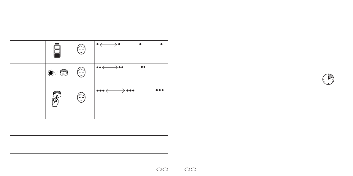
DEENDE
EN
Hinweistöne Stör- und Fehlermeldungen / Hinweistöne Stör- und Fehlermeldungen /
90Sekunden/Seconds
Ursache/
Lautstärke/
Intervall/
Alert tones for error messagesAlert tones for error messages
Batteriestörungsmeldung
Battery error
message
Kontaminations-
meldung /
Contamination
message
Fehlerhafter Verbindungstest
Funk-Gruppe /
Defective connection test of a radio
group
/
90 Sekunden / seconds
90 Sekunden / seconds
10 Sekunden / seconds
Optische und akustische Alarmtöne im Normalbetrieb / Optische und akustische Alarmtöne im Normalbetrieb / Optical Optical
and acoustical alarm tones in normal operating modeand acoustical alarm tones in normal operating mode
Im Normalbetrieb sind keine optischen und akustischen Signaltöne zu hören /
No optical and acoustical signal tones are heard during normal operation.
Beachten Sie bei der Nutzung von zusätzlichen Geräten (z.B. PX-iP Gateway oder
RWM MC Diagnosegerät), dass die Hinweistöne des Rauchwarnmelders in allen Fällen vorrangig zu behandeln sind.
When using additional peripheral devices (e. g. PX-iP Gateway or RWM MC diagnostic
device), note that the alert tones for error messages of the smoke alarm device must
always be given priority in all cases.
Die Alarmtöne „Rauchalarm“ und „Temperaturalarm“ können Sie
durch Drücken der Prüf-/Stopp-Taste für 10 Minuten vorübergehend deaktivieren.
Der Rauchwarnmelder wird in diesen 10 Minuten keine akustischen
Alarmtöne von sich geben. Auch nicht, wenn andere Rauchwarn-
10 Minuten /
minutes
melder in der selben Funk-Gruppe Rauch detektieren. Der Betrieb
der restlichen Melder in der Funk-Gruppe bleibt von dieser Funktion
unberührt.
You can temporarily disable the alarm sounds “smoke alarm” and
“temperature alarm” for 10 minutes by pressing the testing/stop
button.
The smoke alarm device will not send any alarms within these 10 minutes, even if other smoke alarm devices in the same radio group detect
smoke. The operation of the remaining devices in the radio group will
remain unaected.
84
85
Page 44

DEENDE
EN
Die Hinweistöne „Batteriestörungsmeldung“ und „Kontaminations-
meldung“ können Sie durch Drücken der Prüf-/Stopp-Taste für
24Stunden vorübergehend deaktivieren. Das Gerät muss unbedingt
ausgetauscht werden.
You can temporarily disable the alarm sounds “battery alarm message” and “contamination message” for 24 hours by pressing the
testing/stop button. It is necessary to replace the device.
Die Stör- bzw. Fehlermeldung „Fehlerhafter Verbindungstest
Funk-Gruppe“ können Sie NICHT durch Drücken der Prüf-/
Stopp-Taste vorübergehend deaktivieren. Das Test auslösende Gerät
und alle erreichten Geräte verstummen automatisch nach 2 Minuten.
Ein defektes Gerät muss unbedingt ausgetauscht werden.
It is NOT possible to temporarily disable the fault or error message
“Error in radio group connection test” by pressing the testing/stop
button. The device triggering the test and all reached devices are automatically silenced after 2 minutes. A faulty device must be replaced.
24 Stunden /
hours
18 Lichtsignale /
Light signals
Lichtsignal / Lichtsignal / Light signalLight signal
Beschreibung / Description
Lichtsignale der Signal-LED / Lichtsignale der Signal-LED / Light signals of the signal LEDLight signals of the signal LED
Prüfung läuft, bitte warten /
Check in progress, please wait
Inbetriebnahme
(Drücken der Funk-Taste) /
Activation (pressing the radio button)
Lernmodus (ca. 10 Minuten) /
Learning mode (about 10 minutes)
Erfolgreicher Abschluss einer Aktion /
Successful completion of an action
Fehler / Error
Intervall / Interval
1 Sekunde / second
3 Sekunden / seconds
1 Sekunde / second
3 Sekunden / seconds
3 Sekunden / seconds
86
87
Page 45

Impressum
Pyrexx GmbH
Siemensdamm 62
13627 Berlin
Deutschland, Germany
© Pyrexx GmbH
k_503132
Stand der Betriebsanleitung 2021-01
Änderungen vorbehalten
Revision of the brochure 2021-01
Subject to change
 Loading...