

Page 1
Publication PUB-AB7603-008
BridgeWay
Ethernet to Devi ceN e t Gateway
User Manu al
Part No. AB7603
Pyramid Solutions
1850 Resear ch Drive, Suit e 300
Troy, Michigan 48083
Phone 248-524-3890
Web www.pyramid-solutions.com
Page 2

Table of Contents i
© 2004 Pyramid Solutions Inc.
Publication PUB-AB7603-008
Table of Contents
Preface......................................................................... iv
How to Use Thi s Manual ... .............. ...................... iv
Important User Information ................................... iv
Related D o cu mentati o n...... .............. .................... ... v
BridgeWay Module Description. ............................ 1-1
Overview..................................................................... 1-1
Theory of Operation.................................................... 1-2
DeviceNet Featur es............... .......... ......... .................. 1-3
Ethernet Features....................................................... 1-3
IT-Features................................................................. 1-4
System Requiremen ts......................... .......... ............. 1-4
Hardware Description................................................. 1-6
Installation................................................................ 2-1
Installation and Operation Requirements ................... 2-1
Power and Network Connections............................... 2-2
Connecting Power ...................................................... 2-3
Connecting DeviceNet................................................ 2-4
Connecting to Ethernet............................................... 2-4
Configuration........................................................... 3-1
Ethernet Network Configuration ................................. 3-1
DeviceNet Network Configuration .............................. 3-8
DeviceNet I/O Conf ig u ra tion..................................... 3-10
Quick Sta rt ........................... .................... ................ 4-1
DeviceNet Network Configuration .............................. 4-1
DeviceNet I/O Conf ig u ra tion....................................... 4-8
Ethernet Network Configuration ............................... 4-11
Using the Ethernet File System................................ 4-13
DeviceN et Interface. ........................... ...................... 5-1
Network Communications........................................... 5-1
Configuration.............................................................. 5-1
Automatic Ba u d Rate Detection . ......... ................... .... 5-1
Page 3

Table of Contents ii
© 2004 Pyramid Solutions Inc.
Publication PUB-AB7603-008
Slave Device Communi ca tion............................. ........ 5-2
Scan Cycles.... ......... .......... ......... ................... ......... .... 5-2
I/O Message Types .................................................... 5-3
I/O Mapping................................................................ 5-3
Proxy for Group 2 Only Devices................................. 5-3
Run/Idle Mod e........... .......... ......... .......... ................... . 5-4
Automatic Device Re co ve ry (ADR)................. ........... 5-5
Interacti o n with I/O Tables...................... ......... ........... 5-6
EtherNet/IP Interface.............................................. 6-1
Product Features........................................................ 6-1
CIP Objects ................................................................ 6-1
CIP Messaging........................................................... 6-2
Assembly Objects and Connections........................... 6-4
Notes About Using ControlLogix I/O Connections.... 6-10
CIP Bridging ............................................................. 6-11
Modbus/TCP Interface............................................ 7-1
Supported Commands..................................... ..... ...... 7-1
Supported Exception Codes....................................... 7-2
Modbus/TCP Addressing............................................ 7-3
I/O Data Content......................................................... 7-4
I/O Data Format.......................................................... 7-5
File System............... ..................... .......................... .. 8-1
File System Conventions............................................ 8-1
Security....................................................................... 8-2
Structure..................................................................... 8-4
Default Fil e s........... ......... .......... ................... ......... ...... 8-5
Virtual File System...................................................... 8-6
System Files................. ......... .......... ......... .......... ........ 8-6
Configuration Files...................................................... 8-7
Password Files......................................................... 8-11
Other File s...... ......... .......... ......... ................... ......... .. 8-13
BridgeWay Web Page Files...................................... 8 -17
IT Functionality ....................................................... 9-1
Default User Accounts................................................ 9-1
Page 4

Table of Contents iii
© 2004 Pyramid Solutions Inc.
Publication PUB-AB7603-008
The FTP Server.......................................................... 9-2
The Telnet Server....................................................... 9-2
HTTP Server............................................................... 9-8
SSI Functionality......................................................... 9-9
Email Client............... .......... ......... .......... ......... ......... 9-23
Displaying I/O Data on a Web Page......................... 9-24
Status a nd D i a g no stics......... .......................... ........ 10-1
BridgeWay LEDs ...................................................... 10-1
Diagnostic Web Pages ............................................. 10-4
Status Assembl y................ ......... ......... .......... ......... .. 10-7
Specifications.......................................................... 11-1
Environmental Specifica tions ............ .......... ......... .... 11-1
EMC Directive Compliance....................................... 1 1-1
Electri c a l Spe cifications................ .......... ......... ......... 11-1
Mechanical Specifications........................................ 11-2
I/O Data Sizes .......................................................... 11-2
Connectors.............................................................. 12-1
Power ....................................................................... 1 2-1
DeviceNet ................................................................. 1 2-2
Ethernet RJ45........................................................... 12-3
Auxiliary RS-232 9 Pin D-Subminiature.................... 12-4
Warranty ................................................................ 13-1
Support ................................................................... 14-1
Technical Product Assistance .................................. 14-1
Contact Information.................................................. 14-1
Page 5

Preface iv
© 2004 Pyramid Solutions Inc. Publication PUB-AB7603-008
Preface
How to Use This Manual
This manual provides a n overview of the BridgeWay Ethernet to DeviceNet Gateway. It describes how to configure and operat e it.
Important User Information
The data and illustrati ons found in this document are not binding. We reserve the
right to modify our products in lin e with our policy of product development. The
information i n this document is subject to change and should not be consider ed as
a commitment by Pyramid Solutions. Pyramid Solutions assumes no responsibility for errors that may appear in this document
There are many applications of the BridgeWay module. Those responsible for the
use of this device must satisfy themselve s that all neces sary steps have been take n
to verify an application meets all performance and safety requirements including
any applicable laws, regula tions, codes, and standards.
The illustrations and samples in this guide are intended solely for the purpose of
example. Pyramid Solutions does not assume responsibility or liability for actual
use based upon the examples shown in this publication.
DeviceNet is a trademark of Open DeviceVendor Association (ODVA), Inc.
EtherNet/IP is a trademark of ControlNet International LTD.
RSLinx, RSNetWorx are trademarks of Rockwell Software.
MS-DOS and Windows are trademarks of the Microsoft Corporation.
Page 6

Preface v
© 2004 Pyramid Solutions Inc. Publication PUB-AB7603-008
Related Documentation
Document Name Author Web Page
DeviceNet Specifica tion ODVA www.odva.org
EtherNet/IP Specific ation ControlNet
International
LTD.
www.odva.org
Modbus/TCP Schneider
Automation
www.modicon.com/openbus/index.html
Table 2-1 Related Documentation
Page 7

Chapter 1 Module Description 1-1
© 2004 Pyramid Solutions Inc.
Publication PUB-AB7603-008
BridgeWay Module Description
Overview
The BridgeWay Etherne t to DeviceNet Ga teway allows yo u to s eamlessly c onnect
your Information or Control le vel networks with your Device level network.
The Ethernet to Devic eNet Gateway provid es full DeviceNet Master functio nal ity
allowing connectivity to 63 DeviceNet slaves devices along with an Ethernet
TCP/IP interface that suppor ts IT protocols such as SMTP, FTP, HTTP and control protocols such as EtherNet/IP and Modbus/TCP.
Examples of BridgeWay Ethernet to DeviceNet applications:
• BridgeWay can be used as a gateway to connect information or control
level networks to device lev el networks for programming, configuration,
control or data collect ion. (E.g. Modbus/TCP to DeviceNet)
• BridgeWay can provide router/bridge functionality to connect EtherNet/
IP to DeviceNet.
• B ridge Way can pro vide an int erna l web ser ver to a llow re mote vie wing of
data via a web browser and can off er email and file tr ansfer capa bil ities to
enhance your applicat ion.
Page 8
Module Description 1-2
© 2004 Pyramid Solutions Inc. Publication PUB-AB7603-008
Theory of Operation
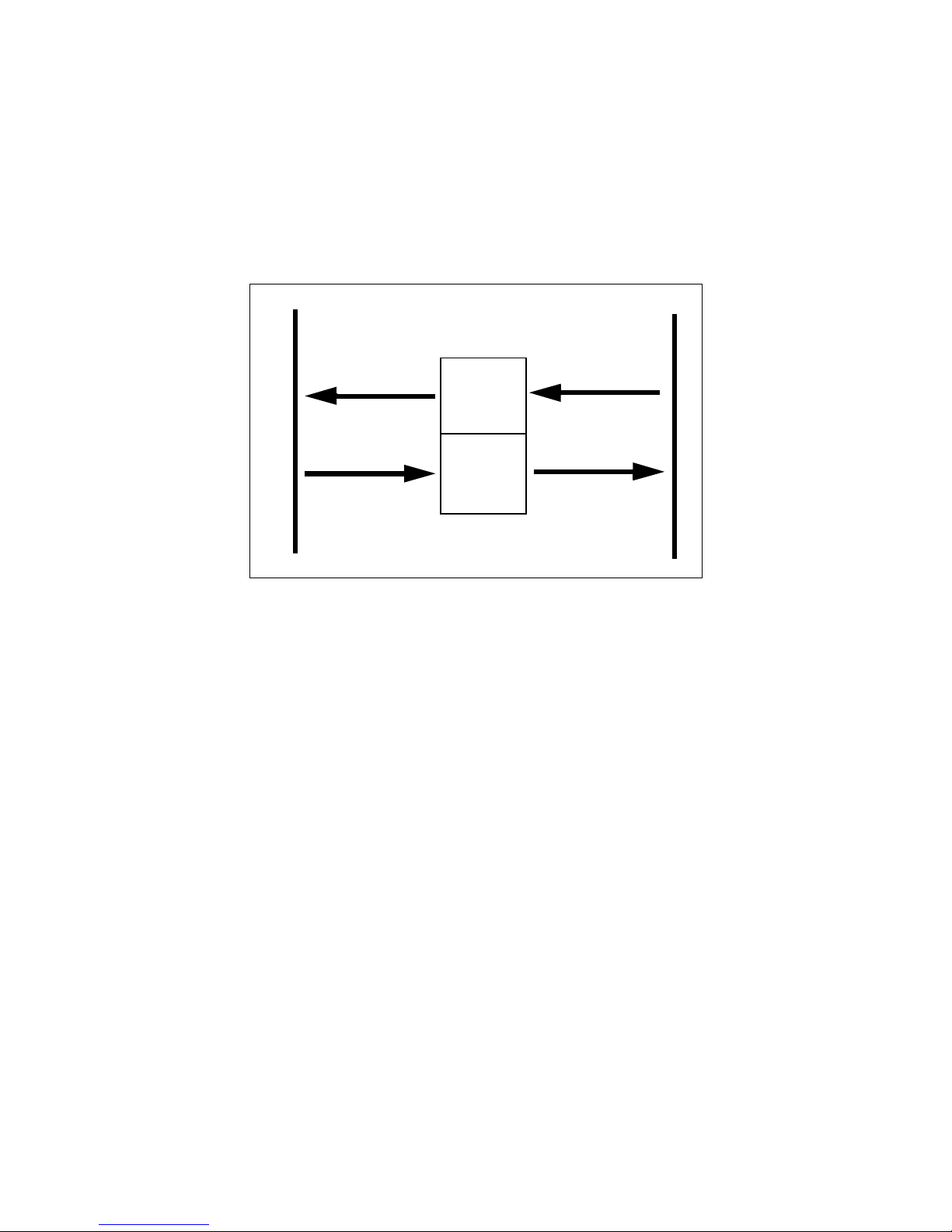
The BridgeWay provides centralized data storage, the “PassageWayTM”, for data
that is shared between the DeviceNet and Ethernet networks. Data is placed into
the PassageWay by one ne twork inter face, a llowing the data t o be read through the
other network interfa ce.
The BridgeWay appears as a single de vice on either netwo rk using standard protocol mechanisms. No special, or extended, protocol features are required of the
devices on either network to read or write the data flowing through the PassageWay; all cross-network activity is transparent to the devices on either network.
Figure 1-1 BridgeWay PassageWay Operation
Ethernet
DeviceNet
PassageWay
Input
Table
Output
Table
Input Data
Output Data
Input Data
Output Data
Page 9

Module Description 1-3
© 2004 Pyramid Solutions Inc. Publication PUB-AB7603-008
DeviceNet Features
• DeviceNet Master scanner functionality supporting up to 63 DeviceNet
slave devices
• Explicit Messaging and Bit Strobe, Poll, and Change of State (COS) I/O
connections.
• Baud rates of 125, 250, and 500 Kbps.
• Automatic baud rate detection optio n may be enabled or dis abled.
• Aut omatic Address Recovery can be configured to repla ce a faulted slave
device with a rep lacement devic e at the sam e M A C ID.
• Configuration Recovery can be configu red fo r slave devices so that a
newly replaced slave can be configured to the same settings of the device
it replaces. Combined with A utomatic Addre ss Re co very thi s feat u re is
known as Automatic Device Recovery (ADR).
• Transfers 500 bytes Input (IN) and 500 bytes Output (OUT) I/O.
Ethernet Features
• Supports the EtherNet/IP protoc ol, Ada pter Class with I/O Server , Message Client, Message Server, and CIP Message Routing.
• Supports the Modbus/TCP protocol with up to 8 simultaneous c onnections. Conforms to the Modbus/TCP specification 1.0.
• Features UDP and TCP/IP protocol stack.
• Supports DHCP/Bootp and ARP for IP Address configura tion.
Page 10

Module Description 1-4
© 2004 Pyramid Solutions Inc. Publication PUB-AB7603-008
IT-Features
• The BridgeWay features a flexible file system with two security levels.
The size available for user files is approximately 1.4 Mbyte.
• An FTP serve r provides easy file management usin g standard FTP clients .
• A Telne t server featuring a command line interface similar to the MSDOS™ environment.
• A a flexible HTTP server (Web server) with Server Side Includes (SSI)
functionality. These are commands to the web server embedded in the
HTML code. This enables the user to access the IN/OUT area using a customizeable web page interface.
• Firmware updates of the DeviceNet control portion of the BridgeW ay
using the RS232 port and BridgeWay Configuration Tool.
• Email client capability. ( The BridgeW ay can only connect to mail ser vers
that do not require a username/pa ssword to access. A mail server such as
that used by many internet provid ers co uld not be used).
System Require ments
The following hardware and softwa re components are needed to use the BridgeWay Ethernet to DeviceNet device.
Required Hardware
• BridgeWay Ethernet to DeviceNet module.
• DeviceNet cabling, power, and devices forming a DeviceNet network.
• Ethernet cabling and power.
• PC or other controller with access to the Ethernet network.
• PC to execute DeviceNet Configuration Soft ware. The DeviceNet slave
devices the Br idgeWay commu ni cat es w ith are sp eci fied using a
DeviceNet Configurat ion Software Tool such as RSNetWorx for
DeviceNet from Rockwell Softwar e or HMS AnyBus Net Tool-DN.
• 24 VDC power to the BridgeWa y module. (DeviceNet power may be
used.)
Page 11

Module Description 1-5
© 2004 Pyramid Solutions Inc. Publication PUB-AB7603-008
Opt iona l Hardware
• A PC with a serial RS232 COM port to be used by the BridgeWay Configuration Tool Softwar e for downl oading firmware updates.
• RS232 null-modem cable (pins 2 and 3 swapped) from the PC to the
BridgeWay module.
• DIN rail to mount the BridgeWay.
Required Software
• DeviceNet configuration softwa re such as RSNetWor x for DeviceNet to
configure DeviceNet devices and BridgeWay’s DeviceNet operation.
RSLinx version 2.31 or later is required.
Optional Software
• BridgeWay Configuration Tool Software to update BridgeWay’s firmware.
Page 12

Module Description 1-6
© 2004 Pyramid Solutions Inc. Publication PUB-AB7603-008
Hardware Description
All connections, whether power or fieldbus, to the BridgeWay are made on one
end of the module. Phoenix connectors are provided for power and DeviceNet
connections. A RJ-style connector is provided for Ethernet connection. There is a
9-pin D-Subminiature con nector for the auxiliary RS-232 port that is used for
field firmware upgrad es. See “Installa tion” on page 2-1 for more details on the
connectors.
There is an 8 position dip switch on the end of the module that can be used to
select a portion of a default IP address that may be used to permit an intranet connection. See “Ethernet Network Configuration” on page 3-1 for more details on
configuring the IP address using the switches.
On the front of the BridgeWay module are 7 LEDs that are used for status indication. These LEDs provide visual status for the overall module, the DeviceNet
interface, and the E the rnet int erfa ce. See “B ri dge Way LEDs” on page 1 0-1 for
details on how the LEDs are used.
The back of the module has a DIN rail mount to allow the module to be mounted
on a DIN rail.
Page 13

Chapter 2 Installation 2-1
© 2004 Pyramid Solutions Inc.
Publication PUB-AB7603-008
Installation
Installation and Operation Requirements
•Power, input and output (I/O) wiring must be in accordance with Class 1, Division 2 wiring methods - article 501-4(b) of the National Electric Code,
NFPA 70 and in accordance with local codes.
•Warning - Explosion Hazard - Substitution of components may impair su itabil-
ity for Class 1, Division 2.
•Warning - Explosion Hazard - When in hazardous locations turn off power
before replacing or wiring modules.
•Warning - Explosion Hazard - Do not disconnect equipment unless power has
been switched off or the area is known to be nonhazardous.
•Terminal tightening torque must be between 5-7 lbs-in (0.5-0.8 Nm).
•For use in Class 2 curcuits only.
•Suitable for surrounding temperature of 65 degrees C maximum.
•Use 60/75 C copper wire only.
Page 14
Installation 2-2
© 2004 Pyramid Solutions Inc. Publication PUB-AB7603-008
Power and Network Connections
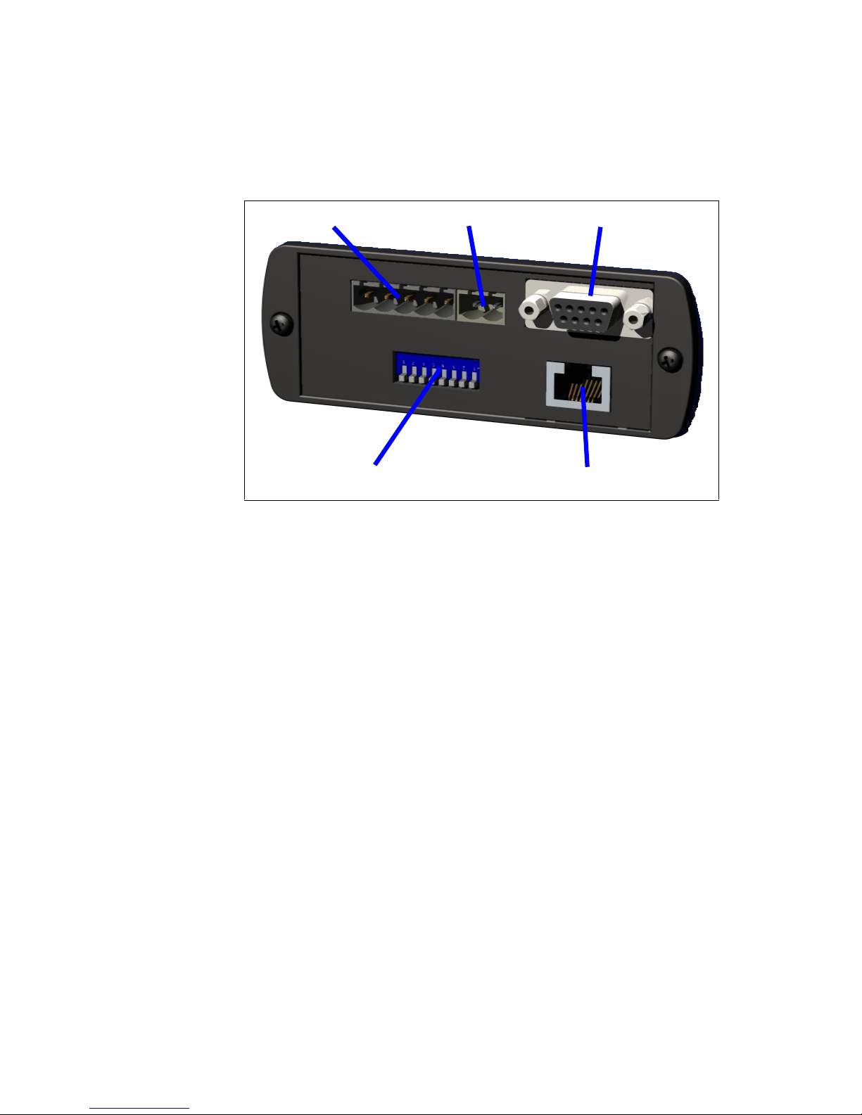
The power and networ k connections to the Bridg eWay are made on the e nd of the
module. Figure 2-1 indicates the location of each connector.
Figure 2-1 BridgeWay Power and Network Connections
DeviceNet Power
Aux RS-232
Ethernet
Ethernet IP Address
Page 15
Installation 2-3
© 2004 Pyramid Solutions Inc. Publication PUB-AB7603-008
Connecting Power
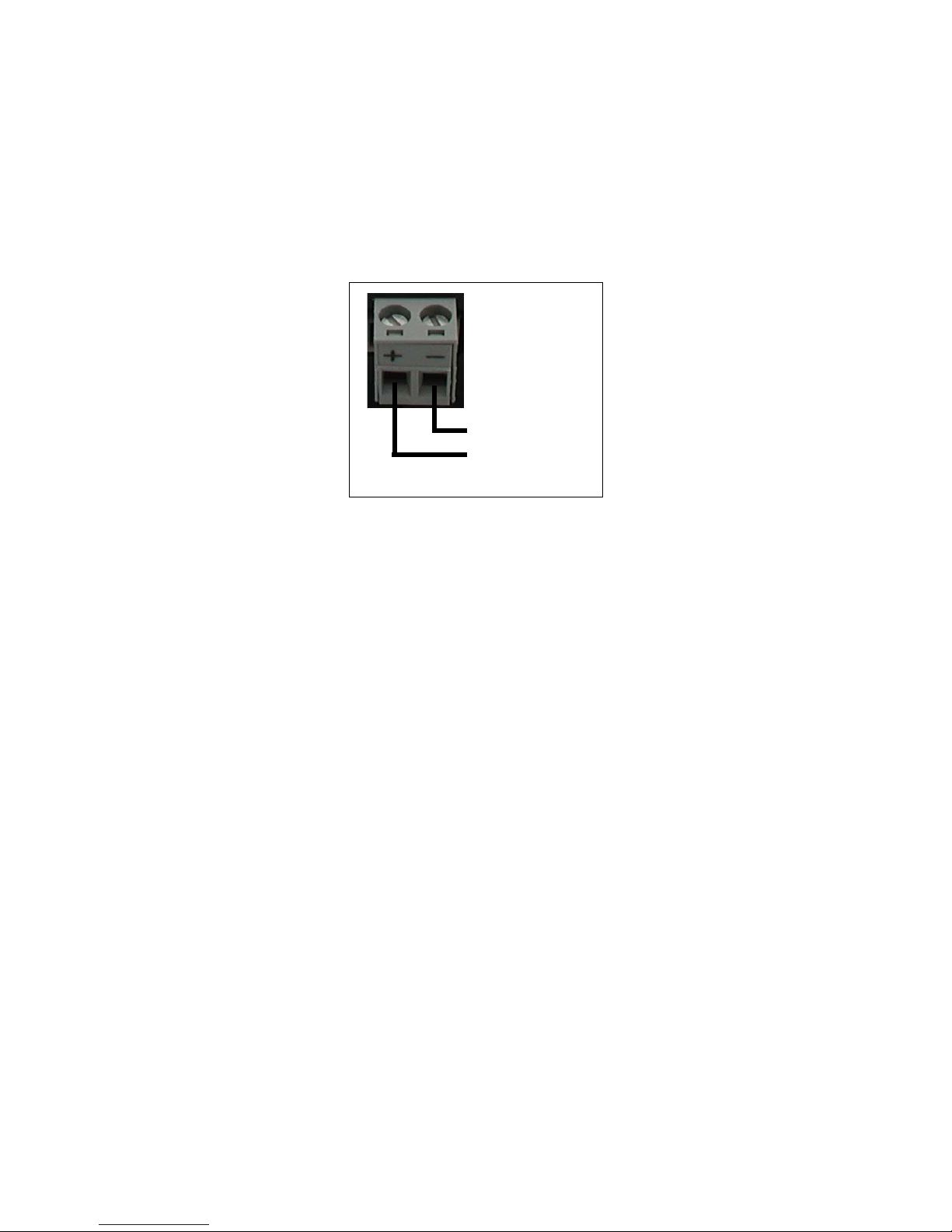
The power connection is a 2-p in terminal block located on the end of the module .
The female terminal block connector is provided with the BridgeWay. Connections to be made are illustrate d in Figure 2-2.
The BridgeWay requires 24 volts DC power. The module will start immediately
when power is applied (There is no On/Of f switch on the module).
Figure 2-2 Power Connection
24VDC Common
24 VDC +
Page 16
Installation 2-4
© 2004 Pyramid Solutions Inc. Publication PUB-AB7603-008
Connecting DeviceNet
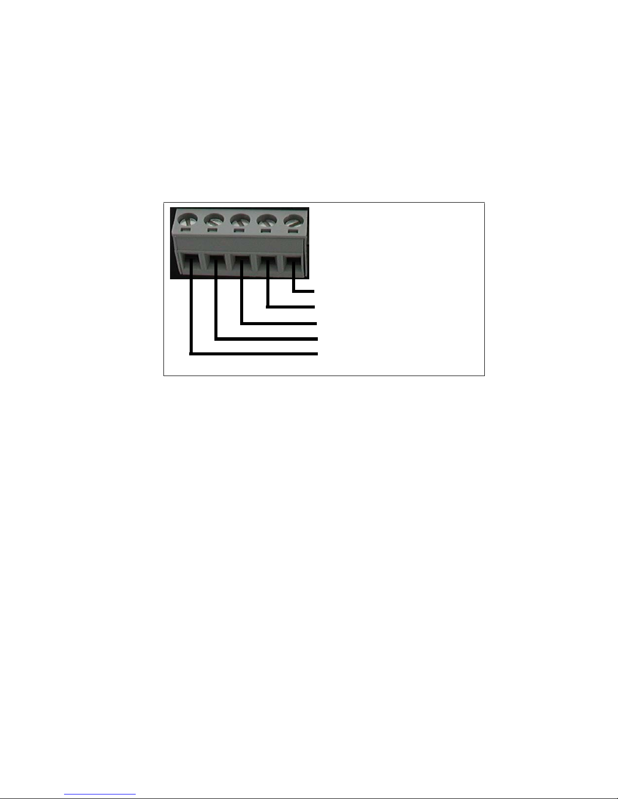
The DeviceNet network connect ion is a 5-pin te rminal block located next to the
power connection on the end of the module. The female terminal block connector
is provided with the BridgeWay. Connections to be made are illustrated in Figure
2-3.
A 120 ohm termination resistor (not pr ovided) may be required for proper network termination. See the DeviceNe t Specification for specific rule s on
DeviceNet connections a nd termination.
For information on setting the DeviceNet network configuration (MAC ID, baud
rate, etc.), see “DeviceNet Network Configuration” on page 3-8.
Connecting to Ethernet
The Ethernet connection use s a standard RJ45 connector (not provided). This is
plugged into the socket on the end of the module.
For informatio n on setting the Ethernet IP configurati on (IP address, DHCP, etc.),
see “Ethernet Network Configuration” on page 3-1.
Figure 2-3 Devi ce N et Co nne cti o n
(Red) Net Power 24VDC +
(Black) Net Power 24VDC Common
(White) CAN High
(Blue) CAN Low
CAN Shield
Page 17

Chapter 3 Configuration 3-1
© 2004 Pyramid Solutions Inc.
Publication PUB-AB7603-008
Configuration
This chapter describes how the BridgeWay Ethernet to DeviceNet Gateway is
configured. The next chapter walks the reader through the configuration of the
BridgeWay using the commonly available configuration tools.
Ether net Network Configur ation
Several methods may be used to set the IP Address. These metho ds include;
IP Address Configuration Switch, DHCP/Bootp protocol, web browser, and the
ARP protocol.
Setting the IP Address with the Configuration Switch
If DHCP/BootP is not enabled or a server is not found and the Configuration
Switch is non zero, on power up the value of the switch is used to form an the IP
Address. The switch represents the binary value of the last byte in the 4 byte IP
address. In this case it is n.
IP address: 192.168.1.n
Subnet mask: 255.255.255.0
Gateway address: 0.0.0.0 (No gateway set)
This is a private address and can only be used on a local intranet. In such a case a
Web Browser such as Microsoft’s Internet Explor er can be used to acc ess the
BridgeWay’s web page which allows changing the IP Address, Subnet mask, and
GateWay address settings.
Page 18

Configuration 3-2
© 2004 Pyramid Solutions Inc. Publication PUB-AB7603-008
DIP Switch Example
The switches are set to 00010100 (20 decimal) (The switch position is shown in
White in the diagram.)
The IP address of the module will be set to 192.168.1.20.
Note: The numbers on the switches on the IP configuration DIP switch do NOT
correspond to bit locations in the address value. In fact, they are reversed. i.e. bit 0
is set by switch 8.
Setting the IP Address Using DHCP/BootP
When DHCP/BootP is enabled and a DHCP or BootP server is found, the IP
address, Subnet mask, and Gateway address is automatically configured by the
DHCP/BootP server. It can be enabled using the BridgeWay’s Settings web page.
Note: The use of DHCP is the default configurat ion for the BridgeW ay as
shipped.
Figure 3-1 IP Configuration DIP Switch
Page 19

Configuration 3-3
© 2004 Pyramid Solutions Inc. Publication PUB-AB7603-008
Setting the IP Address Using Address Resolution Protocol (ARP)
The module’ s I P addre ss can be chan ged using th e ARP command from a PC. Th e
new IP address wi ll be stored in non-vol atile memory. ARP requires the module’s
Ethernet MAC Address that is printed on a label on the back of the module.
Note: ARP cannot be used to change the subnet mask and gateway addr es s of the
BridgeWay. These can be configured using the BridgeWay’s Settings web page.
Switch all 8 switches of the IP Configur ation DIP switch to the ON position.
Note: The ARP/Ping capability is disabled u nle ss all sw itc he s are ON.
On a PC connected t o the B ridge Way on Ethe rnet bri ng up an MS DOS™ window
and type:
arp -s <IP address> <MAC address>
The arp -s command will store the IP and MAC addresses in the PC’s ARP table.
Next type:
ping <IP address>
When the Ping command is exec uted, the PC sends this i nforma tion to the module
using the MAC address. The module detects that it was address ed with the correct
MAC address and adopts the IP address sent by the PC.
Next type:
arp -d <IP address>
The arp -d will remove the static route from the PC’s ARP table.
Switch all 8 switches of the IP Configur ation DIP switch to the OFF position to
disable the feat ure.
This method can be used to reconfigure a module that has been pr eviously configured, or even to reconfigure modules outside the host’s subnet.
Page 20

Configuration 3-4
© 2004 Pyramid Solutions Inc. Publication PUB-AB7603-008
Arp/Ping Example:
The following commands will set the IP address of a BridgeWay with MAC
address 00-30-11-02-00-5E to 65.106.34.252.
arp -s 65.106.34.252 00-30-11-02-00-5e
ping 65.106.34.252
arp -d 65.106.34.252
Page 21
Configuration 3-5
© 2004 Pyramid Solutions Inc. Publication PUB-AB7603-008
Setting the IP Address Using the Web Page
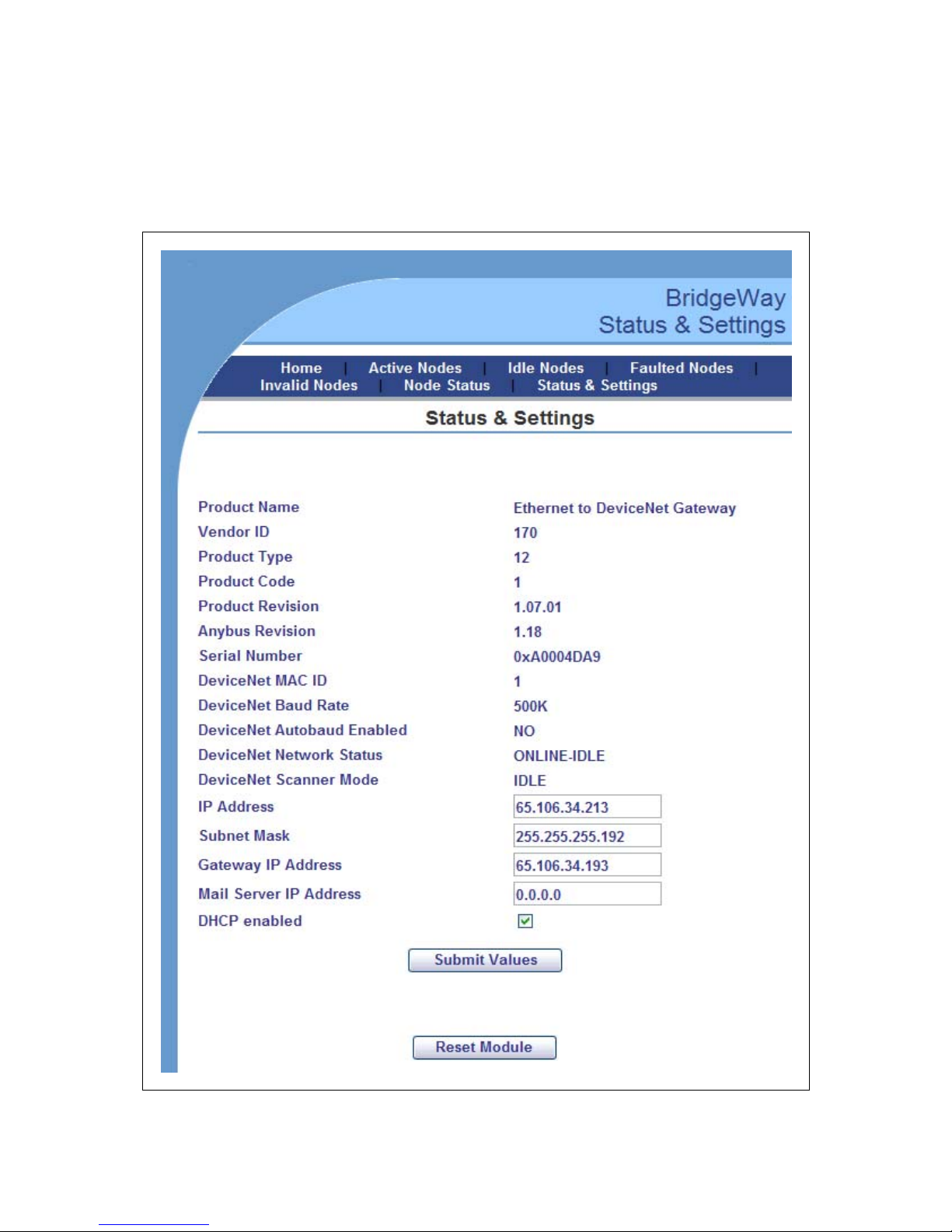
The ethernet addresses c an also be conf igured using the Status and Settings web
page resident on the BridgeWay. The Status and Settings web page appears as
shown below.
Figure 3-2 Status and Settings Web Page
Page 22

Configuration 3-6
© 2004 Pyramid Solutions Inc. Publication PUB-AB7603-008
The IP address, su bnet mask, a nd defaul t gate way address are dis pla yed in t he edi t
boxes on the web page. Changing any values and clicking the Submit Values button will set the addresses in the Bridge Way. Note that a power cycle or module
reset is required for the ch ang es to tak e effect .
The Reset Module button can be used to reset the BridgeWay from the web
browser. The Scanner Mode will display “RESETTING...” while the module
resets and comes back online. The web page will be refr eshed after the module
has booted.
Note: If your web browser is configured t o cache web page s, it may app ear that
the BridgeWay has not changed address after you power cycle the module. Make
sure that the browsers sett ings are configured to always reload pages. On Inter net
Explorer this is done in the Temporary Internet Files Settings dialog by selecting
the “Every V isit” option for when the browser should check f or page changes.
Page 23
Configuration 3-7
© 2004 Pyramid Solutions Inc. Publication PUB-AB7603-008
IP Address Initialization
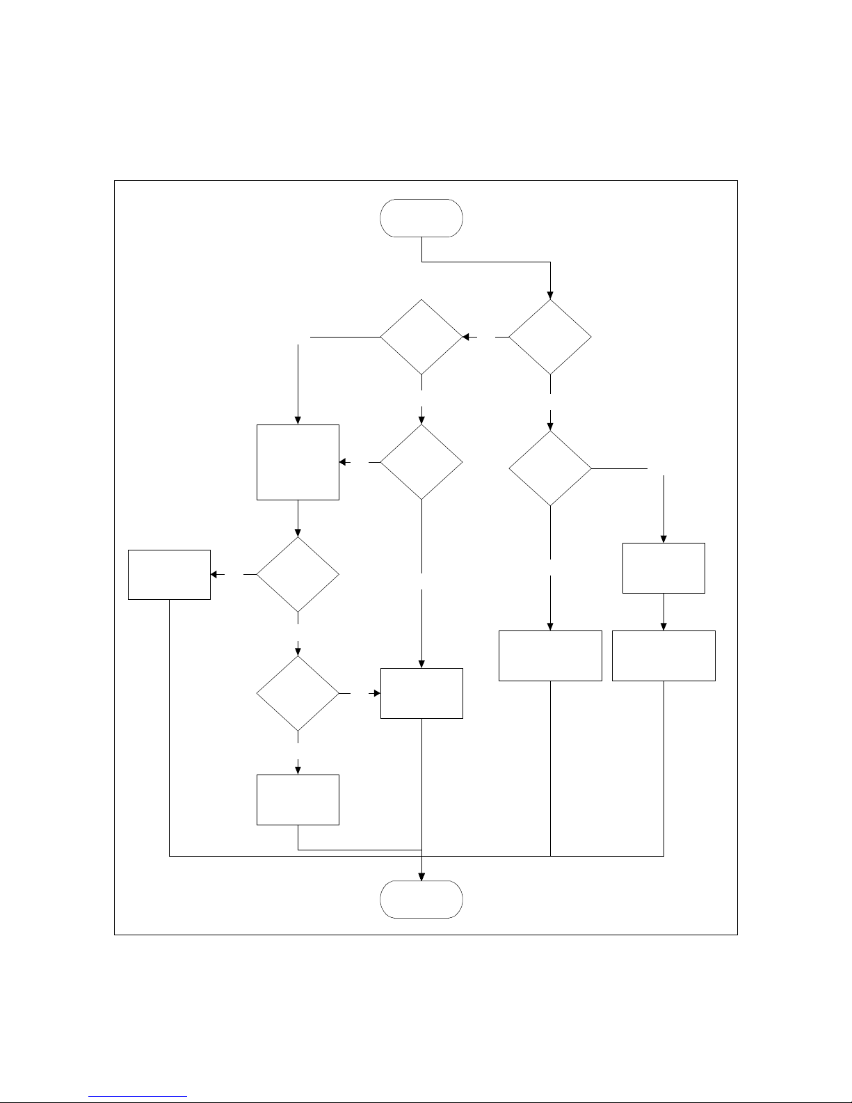
The following flowchart describes how the IP configuration is determine d when
the BridgeWay is powered up.
Figure 3-3 IP Configuration Init ialization Sequence
Start
DIP Switch = 0
No
Yes
IP = 192.168.1.n
Sub = 255.255.255.0
No Gateway
Va lid
Configuration
File ?
Yes
No
DHCP
Enabled?
Yes
No
Use configuration
fro m file
DHCP
Config
Received?
Yes
Use received
configuration
No
V alid
Configuration
File ?
Yes
No
Rema in offlin e
Request config
from DHCP/
BOOTP Server.
Timeout 30 secs
End
DIP Switch =
0xFF
No
Yes
IP = 192.168.1.255
Sub = 255.255.255.0
No Gateway
Enable ARP/Ping
Address Option
Page 24

Configuration 3-8
© 2004 Pyramid Solutions Inc. Publication PUB-AB7603-008
DeviceNet Network Configuration
DeviceNet MAC ID
The DeviceNet MAC ID is software configurable; there are no switches used to
set it.
When first powered, the factory default configura tion sets the MAC ID to 63. The
allowable range for MAC ID is 0 - 63.
A DeviceNet node commissioning tool (e.g. RSNetWorx or NetTool-DN) is used
to set the MAC ID to the desired value for the application. The value is stored in
non-volatile memory and used on subse quent power ups.
DeviceNet Baud Rate
The DeviceNet baud rate is softwar e conf igurable; there are no switches used to
set it. The baud rate can be set to one of the 3 supported rates, or the module can
be configured to use automatic baud rat e detection.
When first powered, the factory default configuration sets the baud rate to
125Kbps. The BridgeWay supports baud rate s of 125, 250, and 500 Kbps.
If the baud rate is to be set, a DeviceNet node commissioning tool is used to set
the baud rate to the desired value for the application. The value is stored in nonvolatile memory and used on subsequent power ups.
If autobaud is desired, the option must be enabled. This is done through a class/
instance editor in RSNetworx, or through the parameter editor in NetTool-DN.
See “DeviceNet Network Configura tion” on page 4-1 for details on setting this
option using these tools .
Note: When the autobaud option is enabled, the baud rate attribute cannot be
changed.
Page 25

Configuration 3-9
© 2004 Pyramid Solutions Inc. Publication PUB-AB7603-008
EDS File
Each device on a DeviceNet network has an associated EDS file containing all
necessary information about the device. This file is used by the network configuration tools, such as RSNetWorx or NetTool-DN, during configuration of the network.
The laster version of the EDS file for the Bridge Way can be downloade d from
Pyramid Solution’s web site, or receive d by contacting Pyramid Solutions.
Page 26

Configuration 3-10
© 2004 Pyramid Solutions Inc. Publication PUB-AB7603-008
DeviceNet I/O Configuration
I/O Mapping
The DeviceNet I /O config urati on def ines the f ormat o f the Input and Out put table s
in the PassageWay, or the mapping of Devi ceNet slave s’ I /O data to th e I/O t ables .
See “Theory of Operation” on page 1-2 for a discussion on the PassageWay and
the use of I/O tables in the BridgeWay. As slaves are added to the BridgeWa y’s
DeviceNet scanner configuration, the location in the I/O tables of each part of t he
slave’s I/O data is determined and stored.
Note: The or ganiz ation o f the I/O t ables is very im porta nt. This de fines the for mat
of the data that will be exposed to the EtherNet/IP scanner. The Input and Output
table formats should be planned and documented to ensure the EtherNet/IP scanner is working with the correct data from the DeviceNet network.
I/O Size Limitations
The size of the I/O data that can be exchanged with the EtherNet/IP scanner and,
hence, the size of the I/O tables is res t r icted as explained below.
• The Input table size cannot be larger than 500 bytes.
• The Output table size cannot be larger than 500 bytes.
• Either table may be empty (size of 0 bytes).
DeviceNet Configuration Tools
The DeviceNet I/ O configur ation i s set usi ng a DeviceNet c onfigu rati on tool. Th is
manual is not intended to replace the user manual for the configuration tool, so
will not provide details on using the tool.
The next chapter provides a n exa mple appli cation, and cover s th e use of Rockwell
Software’s RSNetWorx for DeviceNet and HMS’ NetTool-DN.
Page 27

Chapter 4 Quick Start 4-1
© 2004 Pyramid Solutions Inc.
Publication PUB-AB7603-008
Quick Start
This chapter provides a step by step explanation of configuration of the BridgeWay Ethernet to DeviceNet Gateway. It is intended to be used as a beginner’s
guide to configuring and using the BridgeWa y using RSNetWorx for DeviceNet
or NetTool-DN. It also demonstrates how easy it is to create your own webpage
and upload it to the module.
Requirements: An Ethern et network and a PC connected to that network, running
Windows ™ 98/ME/20 00/XP, Microsoft Internet Explorer 5.5 or higher, a
DeviceNet configuration tool such as Rockwell Software’s RSNetWorx for
DeviceNet or HMS Net T ool-DN. RSLinx version 2.31 or later is requi red.
DeviceNet Network Configuration
Configuration of the Devic eNet network interface involves using a DeviceNet
node commissioning tool to set the BridgeWa y’s MAC ID and baud rate. The following sections expla in how this is done using eithe r Rockwel l Software’s RSNetWorx for DeviceNet or HMS’ NetTool-DN.
Note: The BridgeWay defaults to 125K baud out of the box. If your DeviceNet
network is not running at 125K baud, the BridgeWay must be powered up on a
local network with the node commissioning tool at 125K baud. Do not attempt to
commission the BridgeWay on a network configured at a different baud rate.
Node Commissioning with RSNetWorx for DeviceNet
Step 1: Connect th e m odule to your DeviceNet networ k .
• Make sure a PC running RSNetW orx for DeviceNet is connected to the
DeviceNet network.
• With the BridgeWay un-powered, connect the DeviceNet ne twork cable
to the DeviceNet co nnector of the module. (See “Connecting DeviceNet”
on page 2-4)
• Power up the BridgeWay.
Page 28

Quick Start 4-2
© 2004 Pyramid Solutions Inc. Publication PUB-AB7603-008
Step 2: Locate the module is on the network.
• RSNetWorx allows browsing on the network to identify devices.
• Select the Network menu option and pull down menu.
• Select the Single Pass Browse option and wait for brows ing to complete.
If this is the first time RSNetWorx has been used with a BridgeW ay, the
BridgeWay’s icon should indicate “Unrec ognizable Device”.
Step 3: Register the BridgeWay EDS file in RSNetWorx.
RSNetWorx requires an electronic data sheet (EDS) to recognize a device and its
capabilitie s. An EDS file i s availabl e on the Pyr amid Solutio ns web site . The EDS
file must be registered with RSNet Worx be fore configuration can continue.
• Select the Tools menu option and pull down menu.
• Select the EDS Wizard option.
• Click on Next.
• Select Register an EDS File option and click Next.
• Select Register a Single File and enter, or browse to, the location of the
EDS file for BridgeWay.
• Click Next or Finish for the remaining option screens.
• Select the Single Pass Browse option and wait for brows ing to complete.
Now an icon identifying the device as the BridgeWay module should
appear.
Step 4: Put the Brid geWay in Idle Mode
The BridgeWay powers up in Idle mode, and is controll ed by the EtherNet/IP
scanner through t he output command r egister. Make sur e that th e module is in I dle
mode by verifying that the BridgeWay Status LED is flashing green (the LED is
solid green when the module is in Run mode). If the module is not in Idle mode,
place the connected Ether net scanner in Idle or Program mode.
Page 29

Quick Start 4-3
© 2004 Pyramid Solutions Inc. Publication PUB-AB7603-008
Step 5: Set the Dev ic eN et MAC ID an d Baud Rate
• Select the Tools menu option and pull down menu.
• Select the Node Commissioning option. Another screen appears.
• Click on Browse and choose the DeviceNet network.
• When the browse is completed, double click on the BridgeWay icon.
• Enter the desired M AC address and/or baud rate, then click the Apply but-
ton.
Note: The BridgeWay will automatically reset if a new MAC ID is entered. If
only the baud rate is changed the BridgeWay must be power cycled before the
new baud rate will take eff ect.
Note: When the MAC ID is changed, the BridgeWay’s I/O configuration is
cleared.
Page 30

Quick Start 4-4
© 2004 Pyramid Solutions Inc. Publication PUB-AB7603-008
Step 6: Enabling the Autobaud Option
If it is desirable to have the BridgeWay aut omatically de termine the network baud
rate, the Autobaud option must be enabled.
• Highlight the BridgeWay module by left clicking on its icon.
• Select the Device menu option and pull down menu.
• Select the Class Instance Editor option. A pop up Message box appears.
Click on Yes. Another screen appears.
• There are several parts to this screen. Make sure the check box titled Val-
ues in Decimal is NOT checked. At the t op rig ht is an Object Address
with 3 text boxes. Set the values in these boxes as follows:
- Class set to 3.
- Instance set to 1.
- Attribute set to 64h.
• To the le ft of the Object Class sec tion is o ne titled Servi ce Code. There’s a
text box with a pull down selection titled Description. Pull down the
selections and select “Set Single Attribute”.
• The box titled Data Sent to the Device is now available. At the far left of
this box enter a “01” to enable autobaud, or a “00” to disable it. Then
click on the Execute button.
• A message should a ppear in the Data received from device box saying the
execution was completed.
Note: Changes to the autobaud option co nfiguration do not take effect unti l the
module has been power cycled.
Note: If the BridgeWay is the only master on the DeviceNet network, DO NOT
enable autobaud. Automatic baud detection requires there to be traffic on the network, there is typically no traffic until the master establishes connections.
Page 31

Quick Start 4-5
© 2004 Pyramid Solutions Inc. Publication PUB-AB7603-008
Node Commissioning with NetTool-DN
Step 1: Connect th e m odule to your network
• Make sure a PC running NetTool-DN (version 1.0.0.1 or later ) is con-
nected to the DeviceNet network via the NetTool-DN RS-232 interface
adapter.
• With the BridgeWay un-powered, connect the DeviceNet network cable
to the DeviceNet co nnector of the module. (See “Connecting DeviceNet”
on page 2-4)
• Power up the BridgeWay.
Step 2: Locate the module is on the network.
• Start NetTool-DN on the PC.
• NetT ool-DN starts up and displays a screen prompti ng for a network
name. Enter a name such as “BridgeWay” to refer to the network and
click Ok. A blank screen the n appears.
• Select the Tools menu item and pull down its menu selections. Select
Configure Drivers For... option.
• Highlight the name of the network and click on it. A Driver Dialog box
appears.
• Click on 7262 Serial RS232 DeviceNet Tool Adapter to highlight it and
click Ok. A screen to configure the RS-232 communic at i ons be tween the
Adapter and the PC appea rs .
• Select the PC ser ial port b ei ng used to connect to th e NetTool-DN RS- 232
adapter.
• Set the DeviceNet baud rate to 125K baud. Set th e MAC ID to a value that
will not conflict with devi ces already on the network. (including the
BridgeWay)
• Click Go Online. A confirmatio n message indic ating that the adapter has
gone online should appear. Click Ok.
• NetT ool-DN should now display a network screen with the icons fo r the
devices it finds on the DeviceNet network. If this is the first tim e that NetT ool-DN has been used with a BridgeWay, the BridgeWay’s icon will
indicate “N o EDS fi le regist er s for thi s devi ce ”.
Page 32

Quick Start 4-6
© 2004 Pyramid Solutions Inc. Publication PUB-AB7603-008
Step 3: Register the BridgeWay EDS file with NetTool-DN
NetTool-DN requires an electronic data sheet (EDS) to recognize a device and its
capabilitie s. An EDS file i s availabl e on the Pyr amid Solutio ns web site . The EDS
file must be registered with Net Tool-DN befor e configuration can continue.
•From the Tools menu, select Install EDS Files.
• Enter the path, or browse to the location of the EDS file for the Bridge-
Way.
• Click Open.
• Select the Tools menu option, then Update, and click on the network
name. The BridgeWay icon should be properly displayed on the network
screen.
Step 4: Put the Brid geWay in Idle Mode
The BridgeWay powers up in Idle mode, and is controll ed by the EtherNet/IP
scanner through t he output command r egister. Make sur e that th e module is in I dle
mode by verifying that the BridgeWay Status LED is flashing green (the LED is
solid green when the module is in Run mode). If the module is not in Idle mode,
place the connected Ether net scanner in Idle or Program mode.
Step 5: Set the DeviceNet MAC ID
• Right click on the BridgeWay icon and select Device.
• Pull down the next menu and select Change Node Addr ess.
• Select or enter the desired MAC ID and click Ok.
Note: The BridgeWay will automatically reset if a new MAC ID is entered.
Note: When the MAC ID is changed, the BridgeWay’s I/O configuration is
cleared.
Page 33

Quick Start 4-7
© 2004 Pyramid Solutions Inc. Publication PUB-AB7603-008
Step 6: Enabling the Autobaud Option
If it is desirable to have the BridgeWay aut omatically de termine the network baud
rate, the Autobaud option must be enabled.
• Highlight the BridgeWay module by right clicking with the cursor on its
icon.
• Select the Device menu option and pull down menu, then select Proper-
ties. A parameter screen is displayed.
• Click on Upload. The parameter values will be read from the device.
• Put the cursor “Autobau d” par ameter value. Click to highlight it and then
click again to get a menu. From thi s menu select “Ena ble” or “Di sable” to
enable or disable the autobaud option respectively.
• Click Download to send the mode change to the BridgeWay.
• Click Close.
Note: Changes to the autobaud option co nfiguration do not take effect unti l the
module has been power cycled.
Note: If the BridgeWay is the only master on the DeviceNet network, DO NOT
enable autobaud. Automatic baud detection requires there to be traffic on the network, there is typically no traffic until the master establishes connections.
Page 34

Quick Start 4-8
© 2004 Pyramid Solutions Inc. Publication PUB-AB7603-008
DeviceNet I/O Configuration
DeviceNet I/O configur ation involves using a Devi ceNet configuration tool to se t
the BridgeWay’s scan list and I/O table mapping. The following sections explain
how this is done using either Rockwell Software’s RSNetWorx for DeviceNet or
HMS’ NetTool-DN.
I/O Configuration Using RSNetWorx
Ste p 1: Set up BridgeWay module’ s Device Net sca n list
In most cases it will be necessary to return the BridgeWay to Idle mode as
described in “St ep 4: Put the BridgeW ay in Idle Mode” on page 4-2. Once in Idle
mode the following steps should be taken to configure the scan list.
• Select the Network menu and Browse Single Scan. Wait for browsing to
complete.
• Select the Network menu and Upload. Wait for the device informat ion to
be uploaded from the network.
• Double click on the BridgeWay icon to bring up the module description
screen. Several tabs appea r on the top of the screen.
• Click the Scanlist ta b. The screen shows 2 columns. On the left is a list of
“Available devices” that may be added to the scan list. On the right is a
list of devices that are configured in the scan list.
• Check the AutoMap on Add check box.
• Select the devices whose I/O is to be exchanged with the EtherNet/IP
scanner from the “Available devices” column. Click the “>” button for
each one to move it to the scan list.
• Select the Input tab. The Input mapping screen is displayed. The top por-
tion gives a l ist of the devices in the scan list that the Br idgeWa y receives
input data from. The bottom shows the location in the Input table where
the data will be placed for each device. This shows the format of the
Input table of the BridgeWay. This is the format of the input data
that will be sent to the EtherNet/IP scanner. See “I/O Mapping” on
page 3-4.
Page 35

Quick Start 4-9
© 2004 Pyramid Solutions Inc. Publication PUB-AB7603-008
• Select the Output ta b. The Output mapping screen is displayed. The top
portion gives a list of the devices in the scan list that the BridgeWay will
send output data to. The bottom shows the location in the Output table
where the data will be placed for each device. This shows the format of
the Output table of the BridgeWay. This is the format of the output
data that will be s ent to the Bridg eWay from the Eth erNet/IP scan ner. See “I/O Mapping” on page 3-4
• Click the Apply button, and Yes to download the scanlist to the Bridge-
Way.
• The BridgeWay starts scanning as soon as it finds entries in its scanlist.
However, in Idle mode, output data will not be sent to the devices.
Note: Automap is used in this example to for simplicity. In some cases, the user
may wish to organize the I/O data in other ways; this can be done using the
Advanced data table editor in the Input a nd Output tabs. See the RSNetWorx m anual for complete details.
Page 36

Quick Start 4-10
© 2004 Pyramid Solutions Inc. Publication PUB-AB7603-008
I/O Configuration Using NetTool-DN
Step 1: Set up BridgeWay module’s DeviceNet Scanlist
In most cases it will be necessary to return the BridgeWay to Idle mode as
described in “St ep 4: Put the BridgeW ay in Idle Mode” on page 4-6. Once in Idle
mode the following steps should be taken to configure the scan list.
• From the network display screen right click on the BridgeWay icon and
select Device. Pull down its associated menu and select Properties. This
displays the Parameters screen.
• Click on the Scanner tab. The scan list display screen appears with two
columns. The left column displays a list of devices found on the network
that can be added to the scanlist. The right column displays the devices
that are con figured in the scanlist.
• Click Upload to get the current settings.
• Select the devices whose I/O is to be exchanged with the EtherNet/IP
scanner from the l eft column. C lick th e “>” butto n for each one to m ove it
to the scan list. A screen displaying the I/O configuration for the device
will be displayed; click Ok.
• Click the Input tab. A screen is displayed for mapping the input data.
• Select the device whose input data is to be mapped and click AutoMap.
This sets the form at of the Input tab le of the Bri dgeWay. This is the
format of the input da ta that will be sent to the EtherNet/IP sc anner.
See “I/O Mapping” on page 3-4.
• Click the Output tab. A screen is displayed for mapping the output data.
• Select the device whose output data is to be mapped and click AutoMap.
This sets the format of the Output table of the BridgeWay. This is the
format of the output data that will be sent to the BridgeWay from the
EtherNet/IP scanner. See “I/O Mapping” on page 3-4
• Select the Scanlist tab, and click the Download button to download the
scanlist to the BridgeWay.
• The BridgeWay starts scanning as soon as it finds entries in its scanlist.
However, in Idle mode, output data will not be sent to the devices.
Note: Automap is used in this example to for simplicity. In some cases, the user
may wish to organize the I/O data in other ways. See the NetTool-DN manual for
complete details on how to accompli sh this.
Page 37

Quick Start 4-11
© 2004 Pyramid Solutions Inc. Publication PUB-AB7603-008
Ether net Network Configur ation
Step 1: Connect the BridgeWay Module to Your Network
• Connect the Ethernet network cabl e to the RJ-45 fi eldbus connector on
the end of the BridgeWay.
Step 2: Configure th e BridgeWay IP Ad dress Using Arp/Ping
• Set all 8 switches on the IP Address Configuration DIP switch to the ON
position.
• Turn the power ON.
• Open an MS-DOS™ window on the PC.
• Type ‘arp -s <IP address> <MAC address>’
Substitute <MAC address> with the MAC address of your BridgeWay
module. The MAC address is printed on a label on the back of the module. (Don’t include the “<“or “>” characters shown above.) Separate
every 2 digits of the MAC address with a dash (-).
Ask your network administrator for an unused IP number.
Substitute <IP address> with the IP number you wish to use for the module. (Don’t includ e the “< “or “> ” ch ar act er s.)
Note: The BridgeWay’s subnet mask and gateway address cannot be
changed using this method.
Example:
arp -s 65.106.34.252 00-30-11-02-00-5e
• Type ‘ping <IP address>’
Example:
ping 65.106.34.252
Page 38

Quick Start 4-12
© 2004 Pyramid Solutions Inc. Publication PUB-AB7603-008
• You should see a message similar to below indicating a connection.
Example:
Reply from 65.106.34.2 52 Bytes=32 Time=271ms TTL=30
• Type ‘arp -d <IP address>’
Example:
arp -d 65.106.34.252
The BridgeWay module will now adopt the IP address that was spec ified in the
‘arp -s’ comman d.
• Set all 8 switches on the IP Address Configurat ion DIP switch to the OFF
position.
Page 39

Quick Start 4-13
© 2004 Pyramid Solutions Inc. Publication PUB-AB7603-008
Using the Ethernet File System
Ste p 1: Browse the file system
• Open a web browser window on the PC.
• Type ‘FTP://<IP address>’ in the addre ss field. (Substitute <IP addres s>
with the IP address you are using for the module). (Don’t include the
“<“or “>” char act ers. )
• When prompted for a username enter “admin”.
• When prompted for a password enter “admin”.
You can now browse the file system. You should see subdirectories “/web”, “/
pswd” and “/user” and three files “/index.htm”, “/ehtcfg.c fg”, and “/telwel.cfg.
S t ep 2: Create some Fil es Using Telnet
• Click on the Windows ‘S tart’ menu and select ‘Run.’
• Type ‘telnet <IP address>’. Substitute <IP address> with the IP address
you are using for the mo dule. (D on’t inclu de the “< “o r “> ” characters.)
Example:
telnet 65.106.35.252
• You will be prompted for a username, enter “admin”, and a password,
“admin”.
• The T elnet client will be opened, and connected to the module. You can
now browse the user file system using a command line interface.
• Type ‘help’ for a quick explanation on the available commands.
• Type ‘md mydirectory’. You have now created a directory called ‘mydi-
rectory’.
• Type ‘dir’ to view the directory.
• To move inside the directory, type ‘cd mydirectory’.
• Ty pe ‘mkf ile my file’. You have now created an empty fil e calle d ‘myfi le’.
Let’s put something in it.
• Ty pe ‘append myfil e “Easy file hand ling!”’ . You have now added the line
‘Easy file handling! ’ to your new file.
• Vie w the files contents by typing ‘type myfile’
Page 40

Quick Start 4-14
© 2004 Pyramid Solutions Inc. Publication PUB-AB7603-008
• Exit the telnet program.
• Open a web browser window on the PC.
• Type ‘FTP://<IP address>’ in the addre ss field. Substitute <IP address>
with the IP add ress you are using for the module. Don’t inc lude the “<“or
“>” characters
• The directory and file that you created earlier using the Telnet appli cation
should appear. (If your files are not present, press ‘F5’ to update the window content)
• Don’t close this window yet. If you are not in the root directory, make
sure you are.
S t ep 3: Creat e and Upload a W eb Page
• Open a text editor to create a text file.
• Type the following into the new file including the “<“and “>” charac-
ters:
<html>
<head>
<title>BridgeWay</title>
</head>
<body>
<center><h3>Hello world!</h3>Amazing.</center>
</body>
</html>
• Save the file using the filename ‘hello. htm’.
• To upload the web page to the module, simply drag it to the web browser
window that you opened earlier.
Note: This example requires Windows™ Internet Explorer 5.5 or higher, but it is
possible to use any FTP client. However, the procedure may not be similar to this
example.
Page 41

Quick Start 4-15
© 2004 Pyramid Solutions Inc. Publication PUB-AB7603-008
S t ep 4: View a W eb Page
• Open a web browser window on the PC.
• Type ‘HTTP://<IP add re ss> / hel lo. htm ’ in the UR L field. (S u bsti tut e < IP
address> with the IP addr ess you are using fo r the module). Don’t include
the “<“or “>” characters.
• The web page that you downloaded in the previous step shoul d be dis-
played in the browser.
Page 42

Chapter 5 DeviceNet 5-1
© 2004 Pyramid Solutions Inc.
Publication PUB-AB7603-008
DeviceNet Inte rface
Network Communications
The BridgeWay Ethernet to DeviceNet Gateway acts as a DeviceNet Master or a
slave. The BridgeWay, as a master, can exchange I/O data with up to 63 nodes.
The module can also act as a slave to another DeviceNet Master, exchanging the
content s o f it s I/ O tables with the ma s ter.
Configuration
The BridgeWay is configured using a DeviceNet configuration tool such as
RSNetWorx for DeviceNet or NetTool-DN. The tool will access the module over
the DeviceNet network. The BridgeWa y supports a Scanner Configuration and
Scan List object as the configur at ion interface over DeviceNet.
Automatic Baud Rate Detection
Depending on its configura tion, the BridgeWay can set its DeviceNet baud rate
automatically. If t he autobaud opt ion i s enab led, t he module wi ll d etect t he curr ent
network baud rate and set its baud rate accordingly before joining the network. If
the option is disabled, the module will join the network with the configured baud
rate.
Page 43

DeviceNet 5-2
© 2004 Pyramid Solutions Inc. Publication PUB-AB7603-008
Slave Device Communication
The BridgeWay continuously attempts to establish connections with devi ces configured in the scan list (list of configured slaves). Once connecti ons are established, the module performs all necessary steps to configure the required I/O
messaging.
The BridgeWay provides explicit message proxy services for all group 2 only
slaves. Once any Group 2 only devices are configured, the BridgeWay sends
“keep alive” messages to the devices in addition to the I/O messages. This function prevents the explic it message connections between the BridgeWay and the
slave from timing out. This eliminates the need to re-establish an explicit connection should the BridgeWay need to send configuration data or serve as a proxy.
Scan Cycles
The BridgeWay employs a scan cycle for producing poll and strobe I /O messages.
A scan cycle consists of the following:
• A bit-strobe output message (if devices are configured in the scan list are
configured for bit-strobe).
• A poll command message for each device configured for polled I/O.
• A configurable delay before the next scan cycle.
The configurable dela y is the Inter-Scan Delay (ISD). The ISD is a Scanner Configuration Obje ct attr ibut e. The de lay begins when the last poll com mand mess age
is transmitted and ends after the specified time has elapsed.
The BridgeWay also supports a background polling mechanism. A foreground to
background polling ratio can be specified to allow polling of devices at certain
scan cycle inter va ls.
Page 44

DeviceNet 5-3
© 2004 Pyramid Solutions Inc. Publication PUB-AB7603-008
I/O Message Types
The BridgeWay supports all I/O messaging types specified by the DeviceNet protocol. These inclu de s trobe, pol l, COS, COS Unacknowledge d, Cyclic , and Cyclic
Unacknowledged I/O m essages. I/O mes saging a nd I/O parameter s are c onfigure d
using the DeviceNet configur ation tool.
I/O Mapping
The contents and layout of the data in the I/O tab les is defined during configuration of the scan list. The input and output data of each slave is configured, or
mapped, to specific locations in the input and output tables.
Proxy for Group 2 Only Devices
The BridgeWay provides the capabilities necessary for being a Group 2 Only Client as defined for the Predefined Master/Slave Connection Set. Group 3 explicit
messages destined for a group 2 only device that is configured as a slave to the
BridgeWay will be intercepted and relayed to the slave.
Page 45

DeviceNet 5-4
© 2004 Pyramid Solutions Inc. Publication PUB-AB7603-008
Run/Idle Mode
The BridgeWay has two modes of operation, Run and Idle. In both modes the
BridgeWay’s DeviceNet master maintains communication with slave devices in
its scan list.
In Run mode the BridgeWay sends output data to the slaves and rece ives input
data. Since it is actively sending output data affecti ng slav e device operation, the
BridgeWay rejects atte mpts to al ter its config urati on and disr upt communicati ons;
it must first be put in Idle mode.
In Idle mode the BridgeWay still receives input data from the slaves but it does
not send output data. In Idle mode the BridgeWay co nfiguration can be changed.
The Run/Idle mode of the BridgeW ay is controlle d through the command registers
at the front of the output data from the EtherNet/IP scanner (See “Output Assembly” on page 6-6). The module powers up in Idle mode.
If no EtherNet/IP I /O connecti on is act ive, the Ru n/Idle mode of the BridgeWay is
set through an a ttribute of the Ident ity object. To change the Run/I dle mode, use a
DeviceNet messaging tool and send the following message:
Service: Set_Attribute_Single
Class: 1
Instance: 1
Attribute: 103 (67h)
Request Data: 00 for Idle, 01 for Run
Note: When the BridgeWay is reset or powered up, it begins ope ration in Idle
mode.
Page 46

DeviceNet 5-5
© 2004 Pyramid Solutions Inc. Publication PUB-AB7603-008
Automatic Device Recovery (ADR)
This is a feature of the DeviceNet master which allows a slave node that has
dropped off the network ( Fault, power loss, etc.) to be replaced with another
device of the same type. There are 2 parts to ADR, Address Recovery, and Configuration Recovery.
Note: ADR is only available when using Rockwell Software’s RSNetWorx for
DeviceNet as the configuration tool.
Address R ecovery
Address Recovery is responsible for automatically setting a new device’s addres s
to that of a slave that has lost communications.The steps followed by ADR are:
1. When the master detects loss of a slave, it begins to monitor for a
device at MAC ID 63.
2. An identical device is added to the networ k at MAC ID 63.
3. The master verifies that the new device at 63 is exactly the same kind
as the slave that was lost.
4. The master changes the new device’s MAC ID from 63 to that of the
lost slave.
Configuration Recovery
Configuration Recovery is responsible for setting the configuration of a slave
device to the configurat ion that is stored in the BridgeWay. The slave’s configuration is stored in th e BridgeW ay’s non-vola tile memory. Whenever the BridgeWay
establishes c ommunication with t he sla ve devic e, the c onfigu rati on is downloaded
to the slave.
Configuration recove ry serves 2 purposes. 1. If a new device is added to the network to replace a faulted slave, afte r Address Recovery is completed, Configuration Recovery will configur e the new device. 2. Configuration Recovery
guarantees that the sla ve devices will always run the same configuration.
Page 47

DeviceNet 5-6
© 2004 Pyramid Solutions Inc. Publication PUB-AB7603-008
Interaction with I/O Tables
The DeviceNet interface in the BridgeWay accesses the I/O tables as slave I/O
connections a re processed b y the DeviceNet m aster; there is no buffering or timed
updates of the I/O within the module. Safegu ards are in place to ensur e data integrity by prohibi ting simultaneous access by the Ethernet and Device Net interfaces.
There is no synchronization be tween the 2 network interfaces.
When an I/O c onnection with a slave requires that output data be sent t o the slave,
it will be read from the Output table. The data read is what was placed there by the
last write to the Output table by the Ethernet interface.
When input data is received on a slave’s I/O connection, it is copied to the Input
table. This data is available to be read by the Ethernet interface and sent to the
EtherNet/IP scanne r on the next data exchange.
Page 48

Chapter 6 EtherNet/IP 6-1
© 2004 Pyramid Solutions Inc.
Publication PUB-AB7603-008
EtherNet/IP Interface
EtherNet/IP is based on the Control and Information protocol (CIP) which is also
the application laye r for DeviceNet to exchange data between nodes.
Product Feat ur es
The BridgeWay contains EtherNet/IP Adapter Class functionality. Being an I/O
Server it can respond to requests for I/O messages but it does not generate such
requests. A Scanner device would generate these requests. The BridgeWay supports Message Ser ver and Message Cli ent, func ti onality. Thi s means it can ac t as a
target and origina tor for messaging.
CIP Objects
CIP makes use of abstract object modeling to describe the communications of a
product. Objects are well defined subsets of a device’s functionality. They have
functions th at they perform calle d Services and data varia bles called Attributes. If
more than one copy of an object is needed each copy is called an Insta nce. We
have implemented the same objects as other modules that are based on the CIP
protocol.
Page 49

EtherNet/IP 6-2
© 2004 Pyramid Solutions Inc. Publication PUB-AB7603-008
CIP Messaging
T wo types of messaging are used. The regular or repeated tr ansport of a specific
set of data items is known as Implicit Messaging. Both parties agree in advance
and allocate resource s for the data being transported. The connection ID within
the Implicit message defines the meaning of the data and establishes the transport
rate and transport class. The term Implicit Messaging can be i nterchangeable with
the term I/O Messaging.
A one time transport of a data item where both parties do not know in advance of
what’s being transferred is known as Explicit Messaging. Explicit messaging is
used for point to point type messaging. The protocol of the message data describes
(addresses) t he data to be tr ansferr ed. In obje ct modeli ng the a ddress is in te rms of
class number, instance number, and attribute number.
Messages can be sent as Connected or Unconnected. With Connected Messaging
device resources are reserved in advance of data transfer and are dedicated and
always available . Unconnect ed messaging pro vides a means for a devi ce to send a
request without establishing a connection prior to data transf er. This is accomplished through the UCMM or UnConnected Message Manager of the EtherNet/
IP protocol. With UCMM all objects are accessible.
All Explicit Messages have message data defined in a format called the Message
Router Protocol Data Unit (MR_PDU). There are Requests and Responses.
The MR_PDU Request format includes a Service code, Path Size, Path, and data,
if any for the Serv ice. The Path is an encoded series of bytes or Segments describing the location of the data item involved in the transfer. The Logical Segment is
most often used. It describes the Class, Instance, and Attribute of the data. The
Path may also include a Port Segment. The Port segment describes a path or way
to another network. There are two ports on the BridgeWay, one for EtherNet/IP
and one for DeviceNet.
Page 50
EtherNet/IP 6-3
© 2004 Pyramid Solutions Inc. Publication PUB-AB7603-008
I/O Messaging
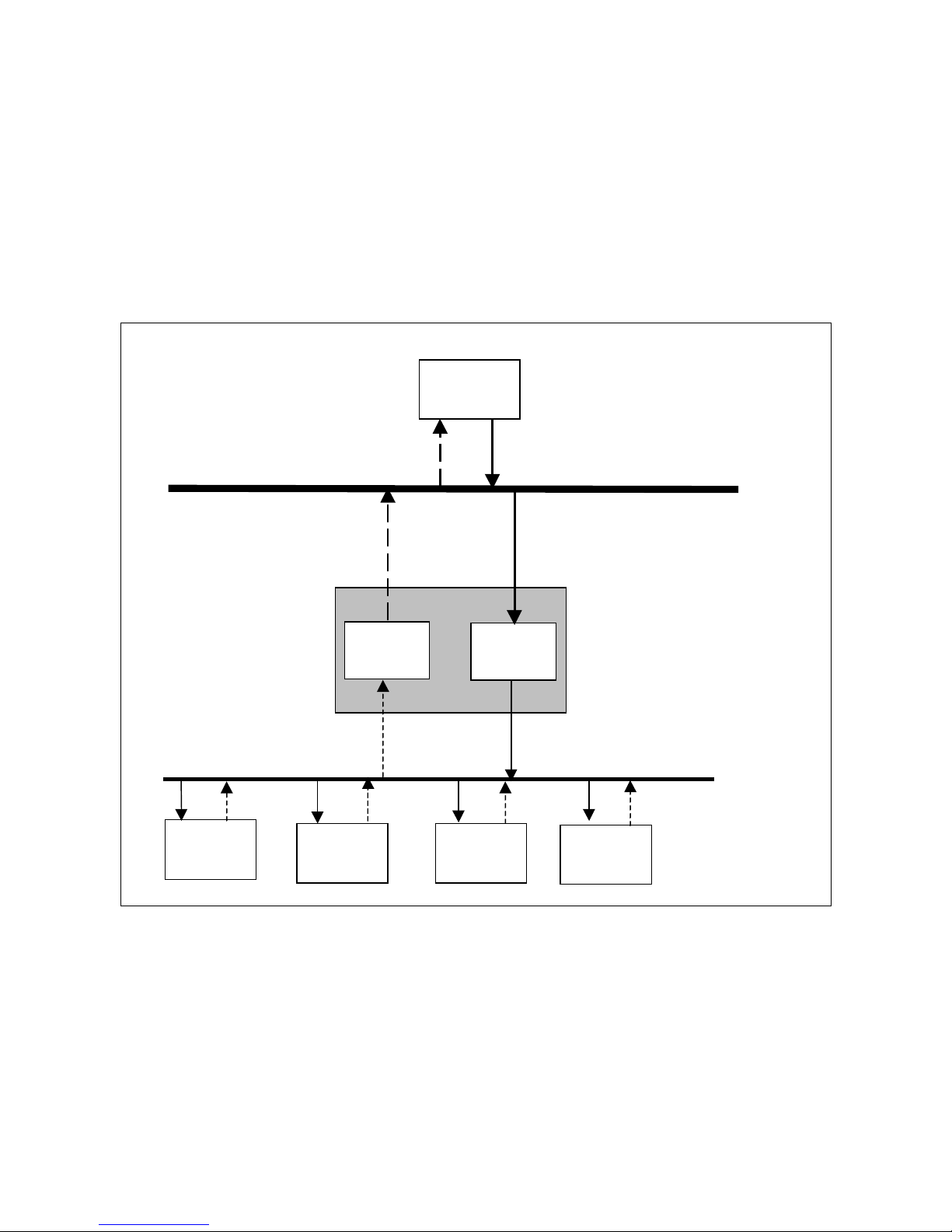
The BridgeWay allows an EtherNet/IP scanner access to the I/O data of
DeviceNet slaves. The data produced by the DeviceNet slaves is collected in the
Input Table (IN) of the BridgeWay and becomes the EtherNet/IP Input I/O to the
EtherNet/IP scanner. EtherNet/IP Output data from the scanner is stored in the
BridgeWay’s Output Table (OUT) and sent to the DeviceNet slaves which consumes it.
Figure 6-1 BridgeWay I/O T ransfer
EtherNet/IP
DeviceNet
Slave
DeviceNet
Slave
DeviceNet
Slave
DeviceNet
Slave
Input
Output
IN
OUT
EtherNet/IP
Input I/O
EtherNet/IP
Output I/O
BridgeWay
DeviceNet
EtherNet/IP
Scanner
Page 51

EtherNet/IP 6-4
© 2004 Pyramid Solutions Inc. Publication PUB-AB7603-008
Assembly Objects and Connections
There are 3 Assembly Object in stances acce ssible fr om EtherNet/I P: input, output
and status. The input and output ass emblies are linke d to the input an d output data
tables. The status assembly provides current status information about the BridgeWay.
The assembl y ins ta nces associated with th ese 3 ass em b lies are list ed be l ow.
Connection Points
Class 1 connections can be established to these assemblies using the connection
points listed in Table 6-2.
Connection sizes, when connecting to the input and output assemblies can be set
according to the size of the I/O data tables configured in the DeviceNet scanner
and the status and command words in the I/O assembli es. (see t he asse mbly formats below) If a conne ction is crea ted wit h a siz e lar g er than that conf igure d in the
DeviceNet scanner, the extra data will be filled with 0.
Assembly
Instance
Description Size in Bytes
100 Input 508 max
101 Status 128
150 Output 508 max
Table 6-1 EtherNet/IP Assembly Instances
Conn
Point
Description Size
in Bytes
Use
3 Heartbeat 0 Output connection point
for input-only connecti ons.
100 Input 0-508 Input connection point.
101 Status 128 Input connection point.
150 Output 0-508 Output connection point.
Table 6-2 EtherNet/IP Connection Points
Page 52

EtherNet/IP 6-5
© 2004 Pyramid Solutions Inc. Publication PUB-AB7603-008
Input Assembly
The input assembly contains a 32-bit status register followed by the data in the
BridgeWay’s input data table.
The input data f ormat and content is determined by the DeviceNe t scanner configuration. The data appears in the ta ble as it is mapped from the DeviceNet input
connections. The input data in the assembly is 504 bytes long; however, only the
size of the configured input data ta ble will be used, the remaining space will be
filled wi th 0 .
The status register is a bit string with the following bit definitions .
Byte
Offset
Size
in Bytes
Description
0 4 Status regis ter.
4Up to
504
Input data.
Table 6-3 Input Assembly Format
Bit Description
0 BridgeWay is in Run mode. (Cleared if in Idle mode.)
1 BridgeWay is faulted.
2 DeviceNet network interface is disabled.
3 Com m u nic at ion ha s failed w ith at least 1 Dev i ceNet
slave.
4 At least 1 DeviceNet slave is an incorrect device type.
5 DeviceNet network interface is bus-off.
6 Duplicate MAC ID error.
7 No DeviceNet power .
8-31 Not used.
Table 6-4 Input Status Register Bit Definitions
Page 53

EtherNet/IP 6-6
© 2004 Pyramid Solutions Inc. Publication PUB-AB7603-008
Output Assembly
The output ass embly contains a 32-bit run/idle register and a 32-bit command register followed by the data in the Brid geWay’s output data table.
The output data format and content is determined by the DeviceNet scanner configuration. The data appears in the table as it is mapped to the DeviceNet output
connections. The output data in the assembly is 500 bytes long; however, only the
size configured for the output data table will be used, the remaining space will be
ignored.
The Run/Idle register is a bit string with the following bit definitions.
Byte
Offset
Size
in Bytes
Description
0 4 Run/Idle register.
4 4 Command register.
8Up to
500
Output data.
Table 6-5 Output Assembly Format
Bit Description
0 System Run Mode. Used in conjunction with the
Local Run Mode bit in the Command register to
determine the run mode of the BridgeWay. Both bits
must be set for the BridgeWay to be in Run mode;
otherwise the module will be in Idle mode.
1-31 Not used.
Table 6-6 Output Run/Idle Register Bit Definitions
Page 54

EtherNet/IP 6-7
© 2004 Pyramid Solutions Inc. Publication PUB-AB7603-008
The Command register is a bit string with the following bit definitions.
Bit Description
0 Local Run Mode. Used in conjunction with the Sys-
tem Run Mode bit in the Command register to deter-
mine the run mode of the BridgeWay. Both bits must
be set for the BridgeWay to be in Run mode; other-
wise the module will be in Idle mode.
1 Fault. Sets a fault condition in the BridgeWay.
2 Disable DeviceNet network.
3 Not used.
4 Reset the BridgeWay module.
5-31 Not used.
Table 6-7 Output Command Register Bit Definitions
Page 55

EtherNet/IP 6-8
© 2004 Pyramid Solutions Inc. Publication PUB-AB7603-008
Status Assembly
The status assembly is a collection of status and diagnostic informatio n for the
BridgeWay DeviceNet interface. The information i n the assembly is updated once
a second.
Note: All information in the status assembly is stored in little endian format. The
least signific ant byte of multi-byte values is stored first.
Byte
Offset
Size
in Bytes
Data Type Name Description
0 4 UDINT Scan Counter The number of DeviceNet I/O scans
that have taken pla ce since the BridgeW ay was powered up.
4 8 64-bit Bit-
string
Faulted Node
Table
Indicates which DeviceNet slaves are
faulted.
Each bit represents the status of the
slave at the corresponding MAC ID.
12 8 64-bit Bit-
string
Auto Verify Error
Table
Indicates which DeviceNet slaves are
the incorrect dev ic e type.
Each bit represents the status of the
slave at the corresponding MAC ID.
20 8 64-bit Bit-
string
Idle Node Table Indicates which DeviceNet slaves are
in Idle mode.
Each bit represents the status of the
slave at the corresponding MAC ID.
28 8 64-bit Bit-
string
Active Node
Table
Indicates which DeviceNet node s are
configured in the BridgeWay’s scan
list. Each bit represents the status of
the slave at the corr es po ndi ng MA C
ID.
Table 6-8 St atus Assembly Format
Page 56

EtherNet/IP 6-9
© 2004 Pyramid Solutions Inc. Publication PUB-AB7603-008
36 4 ASCII[4] Status Display Mimics a 4-character alpha-numeric
display.
If there are no faults, the display indicates the BridgeWay MAC ID and its
Run/Idle status.
If there are faults, the display will
scroll through the MAC IDs of the
faulted nodes and display the error
code associated with each. See
T able 10-6, “Node Status Codes,” on
page 10-5 for a list of error codes.
40 1 USINT BridgeWay MAC IDThe DeviceN e t M AC ID of the
BridgeWay.
41 1 USINT Scanner Status The curren t status of the Dev iceN e t
scanner . See Table 10-6, “Node Status
Codes,” on page 10-5 for a list of status and error codes.
42 1 USINT Scrollin g MA C
ID
The scrolling add ress and status fields
scroll through the address an d status
of all Device Net slaves that are
faulted. This scrolling includes the
BridgeWay scanner itself.
If there are no faulted nodes, both the
scrolling address and status are set to
0.
The scrolling fields change once a second.
43 1 USINT Scrollin g Status
44 20 USINT[20] Reserved
64 64 USINT[64] Node Status Table The current status of each DeviceNet
slave node. Each array element is the
status of the no de at the c orrespo nding
MAC ID.
If a node is not configured in the
BridgeWay scan list, the status v alu e
wil l b e set to 0.
The BridgeW ay scanner stat us appears
at the entry associ ated with the
Bri d geWay MAC I D .
See Table 10-6, “Node Status Codes,”
on page 10-5 for a list of status codes.
Byte
Offset
Size
in Bytes
Data Type Name Description
Table 6-8 Status Assembly Format (Continued)
Page 57

EtherNet/IP 6-10
© 2004 Pyramid Solutions Inc. Publication PUB-AB7603-008
Notes About Using ControlLogix I/O Connections
When configuring I/O connections between a Rockwell Automation ControlLogix EtherNet/IP scanner and the BridgeWay, the Generic EtherNet/IP device
type should be used.
The Run/Idle register is automatically inserted at the front of the output data and
the application has no control over its use. The System Run Mode bit is set
according to the Run/Progra m mode of the contro ller. The Control Logix application sees byte 4 as the beginning of the output assemb ly.
The output size mus t be set to 4 byt es less than the actual assembly s ize to account
for the Run/Idle header that is automatically added by the controller.
The maximum connection size that ControlLogix allows is 500 bytes. Hence the
total 508 bytes of the input and output areas cannot be accessed when using ControlLogix.
Page 58

EtherNet/IP 6-11
© 2004 Pyramid Solutions Inc. Publication PUB-AB7603-008
CIP Bridging
The EtherNet/IP protoc ol provides bridging capabilities to allow a device on the
EtherNet/IP network to acc ess a device on the DeviceNet network through
Explicit Messaging. The BridgeW ay Ethernet to DeviceNet Gateway allows a
device on EtherNet/IP to send an Expli cit Message to a device on DeviceNet and
receive its response. In this way the device on EtherNet/IP can directly access t he
objects of any DeviceNet devic e to confi gure or access data.
To send an Explicit Message to a DeviceNet device, the Unconnected Send or
Forward Open servi ces o f the Connecti on Manager Objec t are used. The the MAC
ID of the destination Device Net node alo ng wi th a networ k port address must be
used in the Unco nn ect ed Sen d and Forw ard Op en serv ic e. Re fer to Volume 1,
Chapter 10 of the EtherNet/IP specification for further informat ion on CIP Bridging.
The BridgeWay supports multi-hop bridged paths. If a routing path routes the
message through the local Devic eNet network to another network, via another
bridge, the Brid geWay will cor rectl y route the message to th e next bri dge using a n
Unconnect ed Send service ov er Dev i ceNet.
Note: The BridgeWay does not support message routing from DeviceNet to EtherNet/IP.
Port Addr esses
Port
Address
Network
2 EtherNet/IP
3 DeviceNet
Table 6-9 Port Addresses
Page 59

Chapter 7 Modbus/TCP 7-1
© 2004 Pyramid Solutions Inc.
Publication PUB-AB7603-008
Modbus/TCP Interface
The BridgeWay supports Modbus/TCP commands. The implementation of the
Modbus/TCP server is done accordi ng to the Modbus/TCP specification 1.0. All
commands acc or ding to clas s 0 and class 1 are impl em en t ed an d a subset of the
class 2 commands.
The module can handle 8 simultaneous conne ctions.
Supported Commands
The following Modbus/TCP commands are supporte d by the BridgeW ay.
Function Code Function Name Class Affects Address Method
1 R ead Coils 1 IN/OUT Bit
2 R ead Input Discrete 1 IN/OUT Bit
3 Read Mult iple Registers 0 IN/OUT Word
4 R ead Input Registers 1 IN/OUT Word
5 Write Coil 1 OUT Bit
6 Write Single Register 1 OUT Word
15 Force Multiple Coils 2 OUT Bit
16 Force Multiple Registers 0 OUT Word
22 Mask Write Regis ters 2 OUT
23 Read/ Write Reg ist ers 2 IN/OUT
Table 7-1 Modbus Commands
Page 60

Modbus/TCP 7-2
© 2004 Pyramid Solutions Inc. Publication PUB-AB7603-008
Supported Exception Codes
An exception code is returned in the response when the BridgeW ay is unable to
service the Modbus request that was rece ived. The fo llowing exce ption code s will
be used by the BridgeWay.
Exception
Code
Name Description
01 Illegal Func-
tion
The module does not support the functi on
code in the query
02 Illegal Data
address
The data address received in the query is outside the initializ ed memory area
03 Illegal Data
Value
The data in the request is illegal
Table 7-2 Exception Co des
Page 61

Modbus/TCP 7-3
© 2004 Pyramid Solutions Inc. Publication PUB-AB7603-008
Modbus/TCP A ddressing
The BridgeWay’s Input (I N) an d Output ( OUT) area s are s et to a max imum size of
508 bytes each. The Status assembly area is 128 bytes. When accessing these
areas, with Modbus commands, the addressing is done according to the foll owing
tables.
Word Bit Address
000h 0000h 0001h 0002h 0003h 0004h 0005h 0006h ... 000Eh 000Fh
001h 0010h 0011h 0012h 0013h 0014h 0015h 0016h ... 001Eh 001Fh
.....
0FDh 0FD0h 0FD1h 0FD2h 0FD3h 0FD4h 0FD5h 0FD6h ... 0FDEh 0FDFh
Table 7-3 Input Addressing
Word Bit Address
400h 4000h 4001h 4002h 4003h 4004h 4005h 4006h ... 400Eh 400Fh
401h 4010h 4111h 4012h 4013h 4014h 4015h 4016h ... 401Eh 401Fh
...
4FDh 4FD0h 4FD1h 4FD2h 4FD3h 4FD4h 4FD5h 4FD6h ... 4FDEh 4FDFh
Table 7-4 Output Addressing
Word Bit Address
100h 1000h 1001h 1002h 1003h 1004h 1005h 1006h ... 100Eh 100Fh
101h 1010h 1111h 1012h 1013h 1014h 1015h 1016h ... 101Eh 101Fh
...
13Fh 13F0h 13F1h 13F2h 13F3h 13F4h 13F5h 13F6h ... 13FEh 13FFh
Table 7-5 Status Addressing
Page 62

Modbus/TCP 7-4
© 2004 Pyramid Solutions Inc. Publication PUB-AB7603-008
Bit Addres s ing Examples
• To reference the first bit of the Input Table use address 0000h.
• To reference the 15
th
bit of the Input Table use address 000Eh (14 deci-
mal).
• To reference the first bit of the Output Ta ble use address 4000h (16384
decimal).
• To reference the 100
th
bit of the Output Table use address 4063h (16483
decimal).
Word Addres s ing Examples
• To reference the first word of the Input Table use address 000h.
• To reference the 10
th
word of the Input T able use address 009h.
• To reference the first word of the Output Table use address 400h (1024
decimal).
• To reference the 100
th
word of the Output Table use address 463h (1123
decimal).
I/O Data Content
The content of the input and output data is the same as the content of the I/O
assemblies used in EtherNet /IP (See section “Input Assembly” on page 6-5, section “Output Assembly” on page 6-6, and section “Status Assembly” on page 6-
8.)
Page 63

Modbus/TCP 7-5
© 2004 Pyramid Solutions Inc. Publication PUB-AB7603-008
I/O Data Format
The BridgeWay transfers I/O data between Modbus/TCP and DeviceNet without
regard to data content or format. Due to this, the user is responsible for making
sure that the devices on either network understand the format of the data.
DeviceNet is a little endian protocol; values are transmitted least significant byte
first. Hence, all dat a in the I/O tables is assumed, by the DeviceNet nodes, to be
stored as little endia n.
Care should b e taken to make sure that the M odbus/TCP maste r ha ndles input data
and transmits output data in a format acceptable to the target DeviceNet devices
(least signifi cant byte first).
Page 64

Chapter 8 File System 8-1
© 2004 Pyramid Solutions Inc.
Publication PUB-AB7603-008
File System
The files system is a fixed-size storage area with a hierarchical directory structure.
Any data, user or applic ation can be st ored i n files wi thin the fi le syst em. Fil es can
be grouped in directorie s for rea dability.
The file syst em featu res two s ecurity leve ls. De pending o n sec urity level, dif fer ent
users can have access to different files and directories. The file system is accessible via FTP, Telnet, and HTTP.
File System Conventions
Case Sensitivity
The file system is case sensitive. This means that the file ‘pyramid.txt ’ is not identical to the file ‘Pyrami d.TXT’ .
Filename / Pathname length
Filenames can be a maximum of 48 characters long. Pathnames can be 256 characters in total, filename included.
File Size
The file size is not restricte d. Naturally, a file cannot be larger than the available
space, see below.
Free space
There is approximately 1.4MB available for user files.
Page 65

File System 8-2
© 2004 Pyramid Solutions Inc. Publication PUB-AB7603-008
Security
The file system features two security levels: Administration and Normal . I n
Administration mode, the user has full access to the file system through FTP and
Telnet. This enables the user to access areas of the file system that are restricted or
inaccessible in Normal mode.
Normal mode is recommended for normal operat ion, so that web pages and other
settings are protected. Administration mode is intended for product development.
The security level can be set individually for each login.
Files within the file syste m can be protec ted from web access through username/
password authorization, see “Password Files” on page 8-11 and “‘web_accs.cfg’”
on page 8-12. It is also possible to configure which IP addresses and what protocols that are allowed to connect to the module, see “‘ip_accs.cfg’” on page 8-8.
Normal mode
The BridgeWay contains a default admin password (“ad_pswd.cfg”) file so when
the module is first powered it oper at es in normal mode (See “Default User
Accounts” on page 9-1). If a valid admin password file (see “Password Files” on
page 8-11) is not found, the module will default operations to Administration
mode.
In normal mode the FTP and T elnet services are only enabled if there is a subdirectory called “\u se r”. Whe n a nor ma l user co n nect s via FTP o r Telnet, this directory will be their root direc tory. The user will not be able to access files outside
this directory and its subdir ectories (administrator files).
In normal mode the BridgeWay provides user/password protection for FTP and
T elnet with a file called “sys_pswd.cfg” in the directory “\user\pswd”. Files in
this director y cannot be accesse d by a web br owser. A default “sys_ps wd.cfg” file
is provided. The default file provides a guest user access to FTP and Telnet. This
user has username “guest” and password “guest”.
Page 66

File System 8-3
© 2004 Pyramid Solutions Inc. Publication PUB-AB7603-008
To prevent unauthorized access this should be changed as soon as possible.
This can be done by changing the username or password. The Administ rator
can access this file to add or remove users or change passwords.
If a user logs into Telnet or FTP using a userna me/password c ombinat ion found in
the admin password file (see “Password File s” on page 8-1 1) he will gai n access
to the entire system.
Administration Mode
At power up the Bridge Way co ntains a default admin password f ile (See “Default
User Accounts” on page 9-1.) A user can login as an administrator by using the
username “admin” and password “admin”.
To prevent unauthorized access this should be changed as soon as possible.
This can be done by changing the username or password.
If no admin password file (see “Password Files” on page 8-11) is found the module operates in Administra tion mode. The user has full access to the file system
via FTP or T elnet. No login is needed for Telnet, and the FTP server accepts any
username/password combination.
Page 67
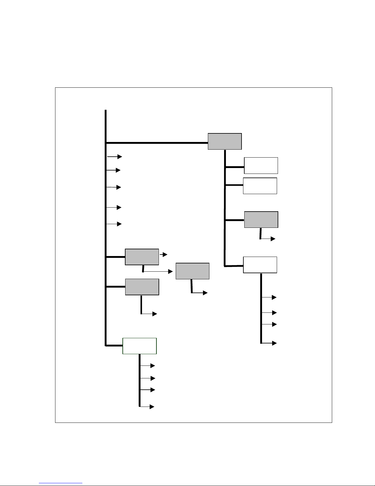
File System 8-4
© 2004 Pyramid Solutions Inc. Publication PUB-AB7603-008
Structure
The figure below illustr ates the struc ture of the file syste m, where the sys tem files
are located, and which areas that can be accessed by normal/admin users.
Figure 8-1 File System Directory Structure
user
R
oot directory for normal users
ethcfg.cfg (Ethernet settin gs, IP etc)
ip_access.cfg
(IP Addresses of
allowed clients)
telwel.cfg (Telnet welcome message)
onoffln.cfg
(ON/OFF-line
configuration
ad_pswd.cfg (Ad m in p asswo r d file)
email_1.cfg
sys_pswd.cfg
(Normal
p
assword fil
e)
email_2.cfg
email_10.cfg
pswd
R
oot directory in admin mo
de
pswd
email
(User defined
email files)
email
email_1.cfg
email_2.cfg
email_10.cfg
(Admin defined
email files)
User1
User2
web
(
Contains
B
ridgeWay W
eb
Pages
)
index.htm
(default web page)
styles
(
files used in
web pages)
Page 68

File System 8-5
© 2004 Pyramid Solutions Inc. Publication PUB-AB7603-008
Default Files
The followi ng dir ecto ri es are al re ad y created on th e Bri dg eWay when first powered;
\pswd,
\user,
\web,
\web\styles,
\user\pswd.
The following files are als o on the BridgeWay;
\pswd\ad_pswd.cfg,
\telwel.cfg,
\ethcfg.cfg,
\index.htm
\user\pswd\sys_pswd.cfg.
These files can be edi ted as needed. Each file is discussed below . The BridgeWay
power must be recycled for any changes to take effect.
Page 69

File System 8-6
© 2004 Pyramid Solutions Inc. Publication PUB-AB7603-008
Virtual File System
The module contains a virtual file syste m, a set of files used to build the default
configurat io n web pa g e. Th ese are hidden files. Th e files can b e repl aced or dis abled, but not erased. A file with the same name in the file system replaces the
file in the virtual fil e system until it is removed.
The virtual file syste m contains the following files:
index.htm
config.htm
configform.htm
store.htm
logo.gif
configuration.gif
boarder.bg.gif
boarder_m_bg.gif
The BridgeWay contains an “index. htm” file replacing its virtual file counter part
to provide a link to the BridgeWay’s Home page.
System Files
The module uses these files for configuration purposes. The system files are
ASCII files and can be edit ed with any text edi tor. Depending on securit y se ttings,
the files may be inaccessibl e for normal users.
Note: These files shall not be used to store any user or application data.
Page 70

File System 8-7
© 2004 Pyramid Solutions Inc. Publication PUB-AB7603-008
Configuration Files
‘ethcfg.cfg’
This file contain s the network configuration and is read by the module at start up.
The settings in this file are affected by SSI commands.
The components and format of the file is shown below:
[IP address] I P address
10.10.12.212
[Subnet mask] Subnet mask
255.255.255.0
[Gateway address] Gateway address
0.0.0.0
[SMTP address] SMTP address – This must be configured in
0.0.0.0 order to send emails
[DHCP/BOOTP] DHCP/BootP ‘ON’-Enabled, ‘OFF’-Disabled
OFF
[Speed] Speed ‘Auto’ Autonegotiation will be used
Auto ’100’ Forces the module at 100mbits
‘10’ Forces the module at 10mbits
[Duplex] Duplex ‘Auto’ Autonegotiation will be used
Auto ’Full’ Forces the module to operate only at full duple x.
’Half’ Forces the module to operate only at half duplex.
Page 71

File System 8-8
© 2004 Pyramid Solutions Inc. Publication PUB-AB7603-008
The contents of this file can be redirected by placing the line ‘[File path]’ on the
first row, and a file path on the second.
Example:
[File path]
\user\eth_settings.cfg
In this example, the settings described above will be loaded from the file
‘user\eth_settings.cfg’.
This permits normal users to acce ss the network configuration settings.
Note: The module needs to be restarted for changes in this file to have affect.
‘ip_accs.cfg’
It is possible to conf igure which IP addresses and what protocols that are allowed
to connect to the module . This information is stored in the file ‘\ip_accs.cfg’. The
file contains one or several of the headers below.
[Web]
[FTP]
[Telnet]
[Modbus/TCP]
[Ethernet/IP]
[All]
Under each header the allowed IP addresses are written. The wildcard ‘*’ can be
used to allow series of IP addresses. I f a protocol header is not given, the system
will use the configurat ion set under the header ‘All’. If the ‘All’ header is not
given, the protocol will not accept any connections.
Page 72

File System 8-9
© 2004 Pyramid Solutions Inc. Publication PUB-AB7603-008
Example:
[Web]
10.10.12.*
10.10.13.*
[FTP]
10.10.12.*
[Telnet]
10.10.12.*
[All]
*.*.*.*
The above example will allow all IP addresses beginning with 10.10.12 to access
all protocols in the module. IP numbers beginning with 10.10.13 will not be able
to access the FTP and Telnet servers. The Modbus/TCP and EtherNet/IP servers
will accept connections from any IP address. The contents of this file can be redirected by placing the line ‘[File path]’ on the first row, and a file path on the second.
Example:
[File path]
\my_settings\ip_access_rights.cfg
In this example, the settings described above will be loaded from the file
‘\my_settings\ip_access_rights.cfg’.
Note: The module has to be restarted in order for any changes in this file to have
affect.
Page 73

File System 8-10
© 2004 Pyramid Solutions Inc. Publication PUB-AB7603-008
‘onoffin.cfg’
The ON/OFF line functionality is by defa ult configured to be triggered by the
Link Status. It can however be configured to be triggered by for example a Modbus command. This is done by creating the file ‘\ onoffln.cfg’.
The components and format of the file is shown below:
[ON/OFF-line trigger ] ON/OFF-line trigger [‘Link’|’ Modbus’]
Modbus Values “Link” and “Modbus”
[Timeout] Timeout value. A value 10 = 1000ms
10
[Commands] Commands (this line is optional)
3, 16, 23 Selects what Modbus commands must be
received during the timeout pe riod.
If the keyword ‘ALL’ is given, the ON/OFF line
functionality will trigger on all Modbus commands
The [Timeou t] and [Commands] heading shall only be given if the ON/OFF-line
trigger value is set to Modbus.
The contents of this file can be redirected by placing the line ‘[File Path]’ on the
first row, and a file path on the second.
Example:
[File path]
\my_settings\on-off-line_configuration.cfg
In this example, the settings described above will be loaded from the file
‘\my_settings\on-off-line_configuration.cfg’.
Note: The module has to be restarted in order for any changes in this file to have
affect.
Page 74

File System 8-11
© 2004 Pyramid Solutions Inc. Publication PUB-AB7603-008
Password Files
‘sys_pswd. cfg & ad _pswd.cfg’
These files contain user / password information for users in normal mode
(‘sys_pswd.cfg’) and administration mode (‘ad_pswd.cfg’). The files shall be
located in ‘\user\ pswd’ and ‘\pswd’ respectively.
These directories are protected from web browser access.
The file format is the following:
User1:password1
User2:password2
...
UserN:passwordN
Example:
JohnQ:Password
In this example, the username is ‘JohnQ’, and the password is ‘Password’.
If no ‘:’ is present, the password will be equal to the username.
Example:
BillH
In this example, both username and password will be ‘BillH’.
Page 75

File System 8-12
© 2004 Pyramid Solutions Inc. Publication PUB-AB7603-008
‘web_accs.cfg’
Files within the file syste m can be protec ted from web access through username/
password protection. To put username/ password protection to files, a file called
‘web_accs.cfg’ must be located in the same directory as the files to protect. If this
file is available , al l files within that directory and its subdirectories will be protected. Multiples of these password files may be present in the system, giving different users access to different files and director ies.
The file format is the same as for the ‘ad_pswd.cfg’ and ‘sys_pswd.cfg’ files,
except that the optional parameter ‘Auth Name’ can be added. The value of this
parameter will be presented in the login window as the “Realm”. If it is not given,
the requested file/pa thname will be presented instead.
Example:
User:Password
[Auth Name]
(Message goes here)
The contents of this file can be redirected by placing the line ‘[File path]’ on the
first row, followed by a list of password fil es.
Example:
[File path]
\user\pswd\my_passwords\web_pswd.cfg
\user\pswd\my_passwords\more_pswd.cfg
In this example, the accepted user/passwords will be loaded from the files
‘\user\pswd\my_ passwords\web_pswd.cfg’ and
‘\user\pswd\my_passwords\more_pswd.cfg’
If any errors in the format of these files is detected the user/password protection
will be ignored.
Page 76

File System 8-13
© 2004 Pyramid Solutions Inc. Publication PUB-AB7603-008
Other Files
‘telwel.cfg’
The default Telnet welcome message can be changed by crea ting this file. It shall
contain the new welcome message in ASCII form.
The contents of this file can be redirected by placing the line ‘[File path]’ on the
first row, and a file path on the second.
Example:
[File path]
\my_settings\telnet_welcome_message.txt
In this example, the welcome message will be loaded from the file
‘\my_settings\telnet_welcome_message.txt’.
Page 77

File System 8-14
© 2004 Pyramid Solutions Inc. Publication PUB-AB7603-008
Email files (email_1.cfg,email_2.cfg to email_10.cfg)
These files contai n predefined email messages and info rmation on how and when
to send them. It is possible to have a maximum of 10 admin defined email file s
and 10 user defined email files. The files must be named ‘email_1.cfg’...
‘email_10.cfg’, and pl aced in t he fol ders ‘\ email’ and ‘\use r\email’ res pectivel y. If
the SMTP server is not configured the email will not be sent (See “‘ethcfg.cfg’”
on page 8-7). If the SMTP server requir es username/password authoriza tion the
email will not be sent. (There wil l not be any indication to the user that the system
failed to send the email.)
The file must have the following for mat.
[Register]
Area, Offset, Type
[Register Match]
Match Value, Mask, Match Operand
[To]
Recipient(s)
[From]
Sender
[Subject]
Subject Line
[Headers]
Extra Headers
[Message]
Message Body
Page 78

File System 8-15
© 2004 Pyramid Solutions Inc. Publication PUB-AB7603-008
Parameter Values Description
Area IN
OUT
Source area in Input/Output
Offset a hexadeci-
mal (0xN)
or decimal
value
Source Offset in Input/Output
Type byte
word
long
Source data type
Match
Value
a hexadecimal
(0xN)
or decimal
value
Value to co m pare w i th source value.
Mask a hexadeci-
mal
(0xN)
or decimal
value
A logical “AND” is performed on the
source data using this Mask before comparing with the Match Value
Match
Operand
<
=
>
How the data is compared with the Match
Value
Recipient(s) text (colon
separated)
Destination email address(es)
Sender text Sender email address
Subject
text (only 1
line)
email subject
Extra Headers
text Optional. It may be useful to send HTML
email
Message
Body
text Message
Table 8-1 Email Parameters
Page 79

File System 8-16
© 2004 Pyramid Solutions Inc. Publication PUB-AB7603-008
Example
[Register]
IN, 0x0003, byte A byte is read from the Input area at location 3.
[Register match]
0x20, 0x7F, > Mask Input byte with 0x7F,
if result greater than 0x20 send email .
[To]
support@your_company.com
[From]
YourDevice@your_network.com
[Subject]
Status
[Message]
Data out of range
Page 80

File System 8-17
© 2004 Pyramid Solutions Inc. Publication PUB-AB7603-008
BridgeWay Web Page Files
The BridgeWay contains several web pages in HTML files to allow changing the
default configuration settings and displaying DeviceNet status. Information displayed on these pages are updated every 2.5 se conds.
NOTE: These web pages require that your browse r support Java. Recent versions
of Microsoft Internet Explor er do not support Java by default. The Microsoft Virtual Machine f or Internet Explorer ma y be downloaded from Microsof t’s web site
at http://v4.windowsupdate.microsoft.com /en/default.asp
.
The files associated with the web pages are in the \web directory and corresponding support files are located in \web\styles.
‘\index.htm’ (Re-Direct Page)
The ‘\index.htm’ file replaces the virtual file index.htm and provides an entry
screen with a link to the BridgeWay’s Home page in the \web subdirector y.
‘\web\index.htm’ (Home Page)
The ‘\web\index.htm’ file provides an information screen with links to othe r web
pages in the \web subdirectory. This is considered the BridgeWa y’s Home page.
‘\web\BW_Settings.htm’ (Settings)
Click on the “Settings” link to display a web page allowing ethernet address settings to be re-config ured including the subnet mask, gateway address, IP address,
and DHCP enable.
‘\web\BW_NodeActive.htm’ (Active Nodes)
Click on the “Active Nodes” link to displ ay a web page providing a status table
of the possible 63 Device Net nodes with an indication of whether the node is configured in the BridgeWay’s scanlist (Act ive). Nodes in the scanlist will have the
word “Active” next to it.
Page 81

File System 8-18
© 2004 Pyramid Solutions Inc. Publication PUB-AB7603-008
‘\web\BW_NodeIdle.htm’ (Idle Nodes)
Click on the “Idle Nodes” link to displ ay a web page providing a status table
of the possible 63 DeviceNet nodes with an indication of whether each node is
idle or in a configuration sta te. This is valid for nodes configured in the BridgeWay’s scanlist. Each MAC ID will have the word “Idle” or a dash (-) next to it.
‘\web\BW_NodeFaulted.htm’ (Faulted Nodes)
Click on the “Faulted Nodes” link to display a web page providing a status table
of the possible 63 DeviceNet nodes with an indication for each node in the
BridgeWay’s scanlist of whether the BridgeWay and node are communicating.
‘\web\AutoVerifyTbl.htm’ (Invalid Nodes)
Click on the “Inva lid Nodes” li nk to di splay a web page pr oviding a status t able of
the possible 63 DeviceNet nodes with a n indication for each node in the BridgeWay’s scanlist of whether the node has failed auto-verification (the device’s type
is incorrect).
‘\web\BW_NodeStatus.htm’ (Node Status)
Click on the “Faulted Nodes” link to display a web page providing a status table
of the possible 63 DeviceNet nodes with additional status information for eac h
node in the BridgeWay’s scanlist.
Page 82

Chapter 9 IT Functionality 9-1
© 2004 Pyramid Solutions Inc.
Publication PUB-AB7603-008
IT Functionality
The module features common IT functionality such as an HTTP server, FTP
server , an Email client, and a T elnet server . This provides easy file management
and the possibility to custom ize the module to provide user-fri endly access to
parameters.
Also, the module can be c onfigur ed to repo rt sel ected infor mation via Email u sing
the Email client.
Default User Accounts
The BridgeWay contains two us er ac counts on init ial powe r up. One account is f or
Administration mode (user name=admin, password=admin). One account is f or a
normal user (username=guest, password=guest).
To prevent unauthorized access this should be changed as soon as possible.
This can be done by changing the username or password. The Administ rator
can access th e Password files to add or remove users or change passwords. ( See
files “‘sys_pswd.cfg & ad_pswd.cfg’” on page 8-11).
Page 83

IT Functionality 9-2
© 2004 Pyramid Solutions Inc. Publication PUB-AB7603-008
The FTP Server
It is possible to upload/download files to/from the file system using a standar d
FTP client. Depending on security settings, different parts of the file system can
be accessed by the user:
Normal Mode / Normal User
The user must login using a valid username/password combination. The root
directory will be the ‘\user’ directory unless the user has admin permission, see
below.
Administration Mode / Admin User
The admin user has unrestricted access to the file system.
The Telnet Server
Through a Telnet client, the use r can access the file system using a command line
interface simila r to MS-DOS™.
Normal Mode / Normal User
The user must login using a valid username/password combination. The root
directory will be the ‘\user’ directory unless the user has admin permission, see
below.
Administration Mode / Admin User
The user must supply a valid admin user/passwor d combination either during
login or by using the command ‘admin’ in order to get admin permission.
The admin user has full access to the file system. The root directory will be “\”
and no files or folders will be hidden.
Page 84

IT Functionality 9-3
© 2004 Pyramid Solutions Inc. Publication PUB-AB7603-008
General Commands
admin
Usage:
admin
Provided that t he user can supply a valid a dmin username/password combination,
this command enables admin acc ess in normal mode. This c ommand has no aff ect
in administration mode.
help
Usage:
help [general|dia gnostic|filesystem]
General commands:
help - Help with menus
version - Display version informa tion
exit - Exit station program
Also try ‘help general|diagnostic|filesystem’
version
Usage:
version
This command will display ve rsion infor mation , serial number and MAC Address
of the module.
exit
Usage:
exit
This comman d cl o ses th e Telnet session.
Page 85

IT Functionality 9-4
© 2004 Pyramid Solutions Inc. Publication PUB-AB7603-008
Diagnostic Commands
The following commands can be viewed by the command ‘help diagnostic’
arps
Usage:
arps
Display ARP stats and table
iface
Usage:
iface
Display net interface stats
sockets
Usage:
sockets
Disp l a y so cket list
routes
Usage:
routes
Display IP route table
Page 86

IT Functionality 9-5
© 2004 Pyramid Solutions Inc. Publication PUB-AB7603-008
File System Operations
For commands where filenames, directory names or paths shall be given as an
argument t he names can be written directly or within quotes. For names including
spaces the filenames must be surrounded by quotes. It is also possible to use relative pathnames using ‘.’, ‘\’ and’.’.
dir
Usage:
dir [path]
Lists the contents of a direct ory. If no path is given, the content of the current
directory is list ed.
md
Usage:
md [[path][ dire ct ory nam e] ]
Creates a directory. If no path is given, the directory is created in the current directory.
rd
Usage:
rd [[path][directory name]]
Removes a directory. The directory can only be removed if it is empty.
cd
Usage:
cd [path]
Changes curr en t directo ry.
Page 87

IT Functionality 9-6
© 2004 Pyramid Solutions Inc. Publication PUB-AB7603-008
format
Usage:
format
Formats the file system. This is a privileged command and can only be called in
administration mode.
del
Usage:
del [[path][file name]]
Deletes a file.
ren
Usage:
ren [[path][ol d na me ]] [[p at h][n e w name]]
Renames a file or directory.
move
Usage:
move [[source path][s ource file]] [[destination pat h]]
This command moves a file or directory from the source location to a specified
destination.
copy
Usage:
copy [[source path][source file]] [[destination path]]
This command creates a copy of the source file at a specif i e d location.
Page 88

IT Functionality 9-7
© 2004 Pyramid Solutions Inc. Publication PUB-AB7603-008
type
Usage:
type [[path][filename]]
Types the contents of a file.
mkfile
Usage:
mkfile [[path][filename]]
Creates an empty file.
append
Usage:
append [[path][filename]] [“The line to append”]
Appends a line to a file.
Page 89

IT Functionality 9-8
© 2004 Pyramid Solutions Inc. Publication PUB-AB7603-008
HTTP Server
The module features a complete HTTP (web) server with Server Side Includes
(SSI) functi ona lit y. Server Side Incl ude s are c omm an d s to the w eb serv er em be d ded in the HTML code. When the web server encounters the commands the
results of the command are inserted in the web page. SSI commands allow easy
access to t he IN and OUT areas of the BridgeWay module. I t is possible to upload
web pages to the module , givi ng acce ss to data in the memory o f the modul e using
a customizab le int erf ace .
Virtual Files
The module contains a set of virtual files that can be used when building a web
page for configurati on of networ k parameters. These virtual files can be overwri tten (not erased) by placing fi le s with the same name in the root of the file system.
By using this feature it is for example possible replace a logo by uploa ding a new
logo named ‘\logo.gif’. It is also possible to make links from a web page to the
virtual configuration page. In that case the link shall point to ‘\config.htm’.
The available virtual f iles are:
index.htm - Shows the contents of config.htm
config.htm - Configuration frame page
configform.htm - Configuration form page
store.htm - Configuration store page
logo.gif - Logo
configuratio n.gif - Configuration picture
boarder_bg.gif - Picture
boarder_m_bg.gif - Picture
Page 90

IT Functionality 9-9
© 2004 Pyramid Solutions Inc. Publication PUB-AB7603-008
Security
All files except files in the direc tories “\user\pswd\”, “\pswd\” and files named
‘web_accs.cfg’ can be viewed by default. Other directories can be protected by
placing a file called ‘web_accs.cfg’(see “Password Files” on page 8-11) in the
directory to prote ct. The file conta ins a list of use rs that a re allowe d to browse tha t
directory.
Also, it is possible to configure which IP addresses are allowed to connect to the
web sever , “‘ip_acc s.cfg’” on page 8-8.
SSI Functionality
SSI functionalit y makes it possible to make web pages interact such as changing
the data in the OUT area of the module. I t is also possibl e to include SSI f unctions
in emails (see “S SI Include s in email s” on pa ge 9-23). The following are available
SSI functions.
Ethernet Address Display Functions
DisplayIP
This function returns the currently used IP address.
Syntax:
<?--#exec cmd_argumen t=’DisplayIP ’-->
DisplaySubnet
This function returns the currently used Subnet mask.
Syntax:
<?--#exec cmd:argument=’DisplaySubnet’-->
Page 91

IT Functionality 9-10
© 2004 Pyramid Solutions Inc. Publication PUB-AB7603-008
DisplayGateway
This function returns the currently used Gateway address.
Syntax:
<?--#exec cmd_argumen t=’DisplayGat eway’-->
DisplayDhcpState
This function returns whether DHCP/BootP is enabled or disabled.
Syntax:
<?--#exec cmd_argument=’DisplayDhcpState(
“Output wh en ON”, “Output wh en OFF”)’-->
DisplayEmailServer
This function returns the current SMTP server address.
Syntax:
<?--#exec cmd_argumen t=’DisplayEma i lS erver’-->
Page 92

IT Functionality 9-11
© 2004 Pyramid Solutions Inc. Publication PUB-AB7603-008
Store Function
StoreEtnConfig
This SSI function stores a passe d IP configuration to FLASH.
Syntax:
<?--#exec cmd_argumen t=’Sto reE tn Co nfi g’-->
Include this line in a HTML page and pass a form with new IP settings to it.
Accepted fields in form:
SetIp
SetSubnet
SetGateway
SetEmailServer
SetDhcpState - value “on” or “off”
Default output:
Invalid IP address!
Invalid Subnet mask!
Invalid Gateway address!
Invalid IP address or Subnet mask!
Invalid Email Server IP address!
Configuration st ored correctly.
Invalid DHCP state!
Failed to store the configuration!
For information about how to change the SSI output, please see “Changing SSI
Output” on page 9-21.
Page 93

IT Functionality 9-12
© 2004 Pyramid Solutions Inc. Publication PUB-AB7603-008
Formatted Display
printf
This SSI function includes a for matted string, which may contain data from the
Input (IN) Output (OUT) area, on a web page. The formatting of the string is
equal to the standard C function pr intf ().
Syntax:
<?--#exec cmd_argumen t=’printf(
“String to write”, Arg1, Arg2,..., ArgN)’-->
Like the standard C function printf() the “String to write” for this SSI function
contains two t ypes of objects: Ordinary c haracters, which are copied to the output
stream, and conversion specifications, each of which causes conversion and printing of the next successive argument to printf. Each conversion specification
begins with the characte r “%” and ends with a conver sion character.
Page 94

IT Functionality 9-13
© 2004 Pyramid Solutions Inc. Publication PUB-AB7603-008
Between the “%” a nd the conversion characte r there may be the following modifiers:
Modifier Description
- Specifies left adjustment of the converted argument in its field.
+ Specifies that the number will always be printed with a sign.
space If the first character is not a sign, a space will be prefixed.
0 Specifies padding to the field with leading zeroes.
# Specifies an alternate output form. For o, the first digit will be
zero. For x or X, 0x or 0X will be prefixed to a non-zero result.
For e, E, f, g and G, the output will always have a decimal point;
for g and G, trailing zer os will not be removed.
width A number specifying a minimum field width. The converted
argument will be prin ted in a field at least this wide, and wide r if
necessary. If the converted ar gument has fewer characters than
the field width it will be padded on the left (or right, if left
adjustment has been requested) to make up the field width. The
padding character is normally space, but can be 0 if the zero padding flag is present.
precision A number, the precision, that specifies the maximum number of
characters to be printed from a string, or the number of digits to
be printed after the decimal point for e, E, or F conversions, or
the number of significant digits for g or G conversion, or the
minimum number of digits to be printed for an integer (le ading
0s will be added to make up the necessary width)
. A period, which separates the field width from the precision.
h A length modifier. “h” Indicates that the corresponding argu-
ment is to be printed as a short or unsigned short.
l or L A length modifier . “L” or “l” indicates that the argument is along
or unsigned long.
Table 9-1 printf Modifiers
Page 95

IT Functionality 9-14
© 2004 Pyramid Solutions Inc. Publication PUB-AB7603-008
The convers ion ch ar act ers and their meaning are sho wn belo w. If the character
after the “%” is not conversion character, the behavior is undefined.
Charac-
ter
Argument
Type
Convert ed To
d, i Byte,Short Signed Decimal Notation
o Byte,Short Unsigned Octal Notation (without a leading
zero)
x,X B yte,Short Unsigned hexadecimal notation (without a lead-
ing 0x or 0X)
u Byte,Short Unsigned decimal notation
c B yte,Short Single character, after conversion to unsigned
char
s char * Characters from the str ing are printed u ntil a “\0”
is reached or until the number of char acte rs indi-
cated by the precision have been pr inte d
f Long Decimal notation of the form [-] m.dddddde+ -xx
or [-]m.ddddddE+-xx where the number of d’s is
specified by the precis ion. The default precision
is 6; a precision of 0 suppresses the decimal
point.
e,E Long Decimal notation of the form [-] m.dddddde+ -xx
or [-]m.ddddddE+-xx where the number of d’s is
specified by the precis ion. The default precision
is 6; a precision of 0 suppresses the decimal
point.
g,G Long “%e” or “%E” is used if the exponent is le ss th an
-4 or greater tha n or equal to the precision; other-
wise “%f” is use d. Trailing zer oe s and tr ai ling
decimal point are not print ed.
%Print a “%”
Table 9-2 printf Conversion Characters
Page 96

IT Functionality 9-15
© 2004 Pyramid Solutions Inc. Publication PUB-AB7603-008
The arguments that can be passed to the SSI function printf are:
Argument Description
InReadSByte(offset) Reads a signed byte from position offset in the
Input (IN) area
InReadUByte(of fset) Reads a unsigned byte from position offset in the
IN area
InReadSWord(offs e t) Reads a signed word (short) from position offset
in the IN area
InReadUWord(offset) Reads a unsigned word (short) from position of f-
set in the IN area
InReadSLong(offset) Reads a signed longword (long) from position off-
set in the IN area
InReadULong(offset) Reads an unsigned longword (long) from position
offset in the IN area
InreadStr ing(offset) Reads a string (char*) byte from position offset in
the IN area
InReadFloat(of fset) Reads a floating point (float) value from position
offset in the IN area
OutReadSByte(offset) Reads a signed byte from position offset in the
OUT area
OutReadUByte(off set) Reads a unsigned byte from position offset in the
OUT area
OutReadSWord(of fset) Reads a signed word (short) from position offset
in the OUT area
OutReadUWord(offset) Reads a unsigned word (short) from position off-
set in the OUT area
OutReadSLong(offset) Reads a signed longword (long) from position off-
set in the OUTarea
OutReadULong(offset) Reads an unsigned longword (long) from position
offset in the OUT ar ea
OutReadString( offset) Reads a string (char*) byte from position offset in
the OUT area
OutReadFloat(offset) Reads a floating point (flo at) value from position
offset in the OUT ar ea
Table 9-3 SSI Functions to Read Data
Page 97

IT Functionality 9-16
© 2004 Pyramid Solutions Inc. Publication PUB-AB7603-008
Note: The I/O data is stored in the same format as it is received and sent on the
DeviceNet network. DeviceNet is a little endian protocol; values are tra nsmitted
least significant byte first. Hence, all data in the I/O tables is assumed, by the
DeviceNet nodes, to be stored as little endian. The web server operates in a big
endian environment. Some data may have to be manipulated to account for byte
ordering when displaying it on a web page.
Page 98

IT Functionality 9-17
© 2004 Pyramid Solutions Inc. Publication PUB-AB7603-008
Formatted Input
scanf
This SSI function reads a string passed from an object in a HTML form, interprets
the string according to the specification in format, and stores the result in the Output (OUT) area accordi ng to the passe d argum ents. The f ormattin g of the st ring is
equal to the standard C function call scanf().
Syntax:
<?--#exec cmd_argument=’scanf(ObjName, format,
Arg1,. .. , Arg N) , Er rV al 1,. .. , Er rv al N’ -->
ObjName The name of the object with the passed data stri ng
format Specifies how the passed string shall be formatted
Argn Specifies where to write the data
ErrValn Optional; spe cifies the value/string to write in case of an error.
Character Input Data and Argument Type
d D ec im al number; byte, sho rt
i Number , byte , short. The number may be in octal (leading
0(zero)) or hexadecimal (l eading 0x or 0X)
o Octal number (with or without leading zero); byte, short
u Unsigned decimal number; unsigned byte, unsigned short
x Hexadecimal number (with or without leading 0x or 0X); byte,
short
c Charact ers; char*. The next input characters (default 1) are
placed at the indicated spot. The normal skip over white space is
suppressed; to read the next non-white space character , use
“%1s”
s Character string (not quoted); char *, pointing to an array of char-
acters lar ge enough for the string and a terminating “\0” that will
be added.
e, f, g Floating-point number with optional sign, optional decimal point
and optional exponent; floa t
% Literal “%”; no assignment is made.
Table 9-4 scanf Formats
Page 99

IT Functionality 9-18
© 2004 Pyramid Solutions Inc. Publication PUB-AB7603-008
The conversion characters d, i, o, u and x may be preceded by the letter “l” to
indicate that a pointer to ‘long’ appears in the argument list rather than a ‘byte’ or
a ‘short’
The arguments that can be passed to the SSI function scanf are:
Default output:
Write su cce ed ed
Write fa ile d
For information about how to change the SSI Output, see “Changing SSI Output”
on page 9-21“.
Note: The I/O data is stored in the same format as it is received and sent on the
DeviceNet network. DeviceNet is a little endian protocol; values are tra nsmitted
least significant byte first. Hence, all data in the I/O tables is assumed, by the
DeviceNet nodes, to be stored as little endian. The web server operates in a big
endian environment. Some data may have to be manipulated to account for byte
ordering when writing it from a web page.
Argument Description
OutWrite Byte(offset) Writes a byte to position offset in the OUT area
OutWrite Word( offset) Writes a word (short) to position offset in the OUT
area
OutWrite Long(offset) Write s a long to position offset in the OU T a r ea
OutWrite String(offse t) Writes a string to position offset in the OUT ar e a
OutWrite Float(offset) Writes a floating point ( float) value to position offset
in the OUT a rea
Table 9-5 SSI Functions to Write Data
Page 100

IT Functionality 9-19
© 2004 Pyramid Solutions Inc. Publication PUB-AB7603-008
Text Function
GetText
This SSI function gets the text from an object and stores it in the OUT area.
Syntax:
<?--#exec cmd arbgument=’GetText(
“ObjName”, OutWriteString (offset), n)’-->
offset specifies the offset from the beginning of the OUT area.
n (optional) specifies maximum number of characters to read
Default output:
Success - Write succee ded
Failure - Write failed
 Loading...