

Pyramid Communications SVR-250 Service Manual

SVR-250 Service Manual
Table of Contents
Foreword ............................................................................................................................................... 2
Specifications........................................................................................................................................ 3
Functional Description..........................................................................................................................4
Multi-Vehicle Format ........................................................................................................................... 4
ESP Priority Format .............................................................................................................................. 5
Local Mic Repeat .................................................................................................................................. 5
Trunking Operation .............................................................................................................................. 5
Emergency Operation ........................................................................................................................... 6
Dual Tone Operation ............................................................................................................................ 6
Auxiliary Receiver Operation ............................................................................................................... 6
WideBand/NarrowBand Channels ........................................................................................................7
Courtesy Beep ....................................................................................................................................... 7
Power Up Channel ................................................................................................................................ 7
Full Duplex Operation .......................................................................................................................... 7
LED Indicators ......................................................................................................................................7
Installation ............................................................................................................................................ 8
Jumpers ................................................................................................................................................. 8
Main Connector .................................................................................................................................... 8
VHF Transmitter Alignment............................................................................................................... 10
VHF Receiver Alignment ................................................................................................................... 11
UHF Transmitter Alignment............................................................................................................... 12
UHF Receiver Alignment ................................................................................................................... 13
700/800/900MHz Transmitter Alignment .......................................................................................... 14
700/800/900MHz Receiver Alignment...............................................................................................15
Programming ...................................................................................................................................... 17
Common Data ..................................................................................................................................... 18
Channel Data ...................................................................................................................................... 19
Transfer ............................................................................................................................................... 20
Remote Help ....................................................................................................................................... 20
ARS-250 Programming ...................................................................................................................... 21
Flash Programming ............................................................................................................................. 22
Theory of Operation............................................................................................................................24
Parts List Main PCB ........................................................................................................................... 26
Parts Locator Main PCB ..................................................................................................................... 28
Schematic Main PCB .............................................................................................................. Foldout 1
Front Panel Assembly ............................................................................................................. Foldout 2
VHF Transmitter ..................................................................................................................... Foldout 3
VHF Receiver ......................................................................................................................... Foldout 4
UHF Transmitter ..................................................................................................................... Foldout 5
UHF Receiver ......................................................................................................................... Foldout 6
700/800/900 MHz Transmitter ............................................................................................... Foldout 7
700/800/900 MHz Receiver.................................................................................................... Foldout 8
Page 1

SVR-250 Service Manual
Foreword
Scope of this manual
This manual contains the specifications, functional description, operating instructions, schematic, parts
locator and parts list for the SVR-250 synthesized vehicular repeater.
This manual is intended for use by qualified service technicians to aid them with installation, interfacing,
alignment and trouble shooting of the SVR-250 when used with other land mobile radios.
Service manual revisions
Component changes, additions and deletions may occur in the circuit design to improve operation and will
be reflected in future releases of this service manual. Specifications and circuit changes are subject to change
without prior notice or obligation by Pyramid Communications.
Safety Information
The SVR-250 is designed to operate within all applicable Federal regulations at the time of manufacture. Proper
operation and service procedures will assure continued compliance with these regulations:
• Do not operate the SVR-250 without an antenna or appropriate RF load connected to the antenna connector.
• Do not operate the SVR-250 in the presence of unshielded electrical blasting caps or explosive environmental
conditions.
• Do not operate the SVR-250 while refueling the vehicle or in the presence of explosive fumes.
• Do not operate the SVR-250 with persons standing closer than 2 feet from the mobile or repeater antenna.
FCC information
The SVR-250 complies with the FCC rules parts 90 and 22 for radio frequency transmitters. The user must apply
for a license to operate the SVR-250 transmitter pursuant to parts 90.243 and 90.247. Other FCC rules may apply
depending on the class of service the user qualifies for. A complete listing of FCC rules and regulations may be
ordered from:
Superintendent of Documents
Government printing office
Washington DC 20402
The following information pertaining to the SVR-250 should be included in the FCC license application:
VHF UHF 700/800/900 MHz
Type Acceptance: LRUSVR-200VB LRUSVR-200U LRUSVR-200M
Output Power: 0.25-2.0W 0.25-2.0W 100mW-600mW
Emission designator:
Frequency band: 150-174 MHz 400-512MHz 764-806(700M), 806-824 or 850-870(800M)
Number of Channels: 20 20 20
11K0F3E/16K0F3E 11K0F3E/16K0F3E 11K0F3E/16K0F3E
Page 2
897-902 or 936-941 (900M)

SVR-250 Service Manual
Specifications
Transmitter: VHF UHF 700/800/900 MHz
Frequency Range: 150-174 MHz 405-425 MHz (UA)
1
764-776, 794-806 (MC,MD)
450-470 MHz (UD) 806-824, 850-870 (MB,MA)
470-490 MHz (UE)
1
897-902, 936-941 (ME,MF)
Rf power out: 250mW - 2W 250mW - 2W 100mW - 600mW
Spurious emissions: -50dBc -50 dBc -50dBc
Freq stability -30°~+60°C: 1.5 PPM 1.5 PPM 1.5 PPM
Modulation: 16K0F3E /11K0F3E 16K0F3E /11K0F3E 16K0F3E2/11K0F3E
Hum and Noise: -40/-37dB (25/12.5kHz) -40/-37dB (25/12.5kHz) -40/-37dB (25/12.5kHz)
Audio response (300-3kHz): Flat or +6dB/octave Flat or +6dB/octave Flat or +6dB/octave
Audio distortion: <3% @ 60% deviation <3% @ 60% deviation <3% @ 60% deviation
Local mic sensitivity: 300mV-5VPP 300mV-5VPP 300mV-5VPP
FCC Type Acceptance: LRUSVR-200VB LRUSVR-200U LRUSVR-200M
Industry Canada Approval: 2390 195 458A 2390 212 113A 2390A-SVR200M
Receiver:
Frequency Range: 150-174 MHz 405-425 MHz (UA)
1
764-776, 794-806 (MC,MD)
450-470 MHz (UD) 806-824, 850-870 (MB,MA)
470-490 MHz (UE)
1
897-902, 936-941 (ME,MF)
RF sensitivity: .35μV .35μV .35μV
Squelch sensitivity: .2μV to 2μV adjustable .2μV to 2μV adjustable .2μV to 2μV adjustable
Modulation acceptance: ±7.5 /±3.75kHz ±7.5 /±3.75kHz ±7.52 /±3.75kHz
Selectivity: 60/57dB (25/12.5 kHz) 60/57dB (25/12.5 kHz) 50dB
Spurious/image rejection: 60db 60db 60db
IMD response: 60db 60db 60db
Frequency stability: 1.5 PPM 1.5 PPM 1.5 PPM
Audio response (300-3kHz): Flat or -6db/octave Flat or -6db/octave Flat or -6db/octave
Audio output: 0-5VPP AC coupled 0-5VPP AC coupled 0-5VPP AC coupled
Local Rx Audio: 400 mW 8 Ohms 400 mW 8 Ohms 400 mW 8 Ohms
Power Requirements:
DC Supply 13.6 VDC 13.6VDC 13.6VDC
Standby 170 mA 170mA 170mA
Receive 250 mA 250mA 250mA
Transmit 1 A @ 2W 1.5A @ 2W 700mA @ 600mW
Physical:
Dimensions: 5.75"W x 8"L x 2.25"H
Weight: 36 oz.
Case: One piece extruded aluminium
1
405-425 and 470-490 available as special order Only
2
16K0F3E & ±7.5kHz available on 806-824 and 850-870 MHz Only
Page 3

SVR-250 Service Manual
Functional Description
Generally, vehicular repeaters are used as mobile extenders in cross-band operation: the link is VHF/UHF/800
MHz simplex and the mobile is Lo-band, VHF, UHF or trunking. In-band operation is possible, but care must be
taken to prevent interference between the mobile's higher power transmitter and the repeater receiver. Proper
frequency selection and antenna placement are important even in cross-band operation, but especially for inband
use. Low power pre-selector cavities may be placed in line with the repeater antenna cable since it is simplex and
low power.
Important Note
)
The SVR-250 is designed to operate on simplex frequencies; part of the multi-vehicle format dictates that
all of the SVR-250s must be able to monitor all link traffic on site and be able to determine if a handheld is
transmitting, or if other repeaters are transmitting. The handhelds must transmit CTCSS, but should be carrier
squelch receive. The handhelds should not use CTCSS decode if the repeater is utilizing the multi-vehicle
format, as this will interfere with the priority sampling which is essential for multi-vehicle operation. Also, the
handhelds would have to have different encode and decode tones in order for the repeater to be able to tell the
difference between handhelds and other repeaters, so the handhelds would not be able to hear each other. The
repeaters should not transmit CTCSS unless used only in a single vehicle environment.
When the user leaves the vehicle, they activate the SVR-250 via their mobile radio front panel or a separate
switch. When the mobile radio is receiving carrier and proper tone, the SVR-250 will begin transmitting on the
handheld’s receive frequency. The user is able to hear and respond to all radio traffic, including other handhelds
at the site. The SVR-250 can be programmed to give the handhelds priority in a conversation by periodically
sampling for handheld activity (carrier and proper tone) during base-to-portable transmissions. During sampling,
if the SVR-250 detects a handheld transmission, it will cease transmissions, key the mobile radio and repeat
portable-to-base. This allows the handheld to respond during repeater hang time or during full duplex interconnect
calls. Priority sampling can be enabled/disabled through PC programming and the interval can be programmed
between .25 seconds and 2.5 seconds in .25 second increments.
The SVR-250 has a programmable time out timer for base-to-portable transmissions. If the mobile COR is
active for more than the programmed time (and the SVR-250 is the priority unit) it will send a double blip and cease
transmission until the mobile COR is inactive. The time-out is in affect regardless of whether the SVR-250 is
programmed for priority sampling or not.
Multi-vehicle operation
The SVR-250 has 2 different multi-vehicle priority formats; both are compatible with the existing SVR-200
and Motorola PAC/RT formats. The new SVR-250 with ESPTM logic has enhanced features that ensures a priority
vehicle is selected and ready to transmit during the idle time rather than during voice transmissions. The 2 formats
are explained below:
SVR-200 Legacy format
When the SVR-250 is first activated, it will transmit a short “lock tone” that alerts the user that the system
is functioning. It will then assume the priority status and be ready to repeat any base-to-portable or portable-tobase transmissions. If another unit arrives on scene and is activated, it too will transmit the “lock tone”; when
the first SVR-250 detects the lock tone from the second unit, it will increment a “priority counter” and will no
longer repeat any transmissions. The recently arrived unit will be the priority repeater, and the first unit will be
1 count away from priority. This process will continue for each unit that arrives at the site, creating a priority
hierarchy for up to 256 vehicles, each with a unique count and only one unit at priority status. The SVR-250 will
not transmit its lock tone if the radio channel is busy when first enabled. It will wait in non-priority status until
all transmissions cease, then send its lock tone and become the priority unit.
Page 4

SVR-250 Service Manual
Even though the other SVR-250s are not at priority status, they will continue to monitor the channel for
activity. If the priority unit were to leave the scene or become disabled, the other units will detect the condition
to repeat and determine that there is no priority unit repeating the transmission. They will then begin to decrement
their priority counters until one of them reaches the priority status and begins repeating the transmission. Since
the SVR-250s are all at different counts, only one will reach priority status and begin transmitting. The other
units will sense the new priority repeater and cease counting down, preserving the priority hierarchy.
If another unit were to arrive from a different scene and it is still the active priority, there will be two active
repeaters on the air when a condition to repeat exists. When one of the SVR-250s unkeys to check for handheld
activity, it will detect the presence of the other active SVR-250 and increment its priority counter and cease
transmission. This is the self clearing mode to prevent radio collisions.
ESPTM Priority
The SVR-250 Enhanced Sensor Priority works similar to the SVR-200 and PAC/RT formats and is completely
backward compatible with those systems. The SVR-250 determines if there is a priority (and re-establishes the
priority if missing) during idle time between conversations rather than at the critical start of a conversation. When
a condition to repeat exists, the SVR-250 is always ready.
The priority SVR-250 will transmit a short tone burst every 10 seconds. This serves 2 purposes: It informs
the handheld operator that they are still within range of the vehicle and it alerts the non-priority units that a priority
vehicle is still on scene. As long as the non-priority units hear this "beacon" every 10 seconds, they preserve their
counts and maintain the priority hierarchy. If the priority vehicle leaves the scene, after 10 seconds, the nonpriority vehicles will not hear the "beacon" and begin counting down. When one of the counts=0, that SVR-250
will send lock tone for 800 mS, assume priority and begin sending the "beacon" tone every 10 seconds as before.
Since the "beacon" tone must be heard every 10 seconds, it does not have busy carrier lock out and will send the
tone if 2 handhelds are communicating directly or in the presence of co-channel interference.
Local Mic Repeat
If the handheld operator is out of the vehicle and their partner still in the vehicle were to key the mobile radio
using the local mic, the SVR-250 will detect the local PTT and repeat the transmission to the other handhelds so
that both sides of the conversation will be heard by everyone on the link. The local mic repeat function can be
enabled/disabled via the PC software.
The SVR-250 also has a local receive audio speaker jack that enables the person in the vehicle to monitor
portable-to-base transmissions that are being repeated through the mobile.
If the users wish to communicate portable-to-portable without accessing the mobile repeater, they may
transmit on the same frequency without CTCSS (or a different CTCSS); the SVR-250 only responds to carrier
and proper tone from the handhelds.
Trunking operation
When the SVR-250 is connected to a trunking mobile and the handheld operator wishes to access the system,
they key their handheld briefly then release. The SVR-250 will attempt to acquire a voice channel on the trunking
system by keying the mobile for 800mS and monitoring the on-air detect line from the mobile. If it does not see
the radio transmit at all (system is busy), it will send a low tone to the hand held operator to alert them that the
system is busy. The SVR-250 will automatically retry every 5 seconds and send busy tone to the handheld with
each unsuccessful attempt to indicate progress of the call attempt. If unsuccessful after 30 seconds, the SVR-250
will transmit intercept tone to alert the handheld operator that the call attempt failed.
Page 5

SVR-250 Service Manual
When the SVR-250 detects that the mobile is transmitting, it will continue to monitor the on-air line until the
transmitter remains keyed for at least 250mS to ensure that the radio is not handshaking or retrying. After
successful acquisition of a voice channel, it will continue to hold the mobile PTT active for 2 seconds and transmit
a go-ahead blip to the handheld operator. The user then keys their handheld to speak on the voice channel. If the
user does not key up within the 2 second period, the SVR-250 will unkey the mobile and send intercept tone as
before.
If the user keys their handheld only once, or they key the first time for more than 1 second, the SVR-250 will
cancel the call attempt and send intercept tone to the handheld operator. All of the queuing and error tones will
only be sent if the handheld is not transmitting to ensure that the user hears the proper tones.
The SVR-250 can also be programmed to work in a similar way for use with the MSV mobile satellite phones,
except the time delays are extended to work properly within the network.
Emergency Operation
The SVR-250 can be programmed for Emergency operation on a per channel basis. If enabled, the SVR-250
will scan for 2 different CTCSS tones or DCS codes. The secondary tone/code is used to indicate an Emergency
condition from the portable and will assert an output pin when decoded. There are 2 different Emergency formats:
Emg output only or Emg output with voice repeat. Emg output only will assert pin 10 on the main cable for as
long as the secondary tone/code is being received; it is used as a momentary output to the mobile to initiate an
Emergency sequence. This is the most common configuration with Motorola or MA/Com radios. Emg output
with voice repeat will assert pin 10 as before, but will also key the mobile and repeat portable-to-base as long as
the secondary tone/code is being received. This format is used with the Tait mobiles. Additionally, there is a solder
jumper on the main logic PCB that determines if the Emg output signal pulls to ground (NO) or breaks ground
(NC).
Dual Tone Operation
The SVR-250 normally requires its own frequency and earlier technology suffered when there was strong
co-channel interference present. The SVR-250 can be programmed for dual CTCSS/DCS receive that will
eliminate interference from co-channel users. The portable radios will still be carrier squelch receive, but the
SVR-250s will be programmed with a CTCSS/DCS encode that is different from the primary tone/code decode.
The secondary tone/code must be the same as the encode tone/code. During base-to-portable transmissions, the
SVR-250 will sample as before. If it sees carrier and primary tone, it will reverse direction and repeat portableto-base. If it sees secondary tone (another SVR-250 transmitting) it will cease transmission and become nonpriority. If it sees carrier with no tone (or neither programmed tone) it will ignore the co-channel interference.
If three consecutive samples have co-channel interference, the SVR-250 will change the sampling rate to 2.5S
(maximum) to reduce the effects of the extended sample time, until the co-channel signal is no longer present.
Dual Tone receive and Emergency operation are mutually exclusive.
Auxiliary Receiver Operation
In operations where the vehicles do not transmit mobile-to-mobile (half duplex), the non-priority vehicular
repeaters will not see mobile COR when a priority vehicular repeater keys its mobile during portable-to-base
transmissions. This can cause the non-priority repeaters to incorrectly assume priority. The SVR-250 can be fitted
with an additional 16 channel scanning receiver that is programmed for the mobile transmit frequency. This
Auxiliary receiver can have up to 16 mobile transmit frequencies programmed into it and will provide the mobile
COR indication needed for the non-priority repeaters to remain at non-priority. The Auxiliary receiver option can
be programmed to operate on a per channel basis.
Page 6

SVR-250 Service Manual
Wide Band / Narrow Band Channels
The SVR-250 can be programmed for Wide/Narrow band operation on a per channel basis. Wide band
operation is 25kHz for UHF and 800 MHz, 30kHz for VHF. Narrow band is 12.5kHz for UHF and 800 MHz,
15kHz for VHF. VHF channels can be in 5 or 6.25kHz steps on a per channel basis. UHF is programmed in
12.5kHz steps. 700/800/900 MHz are programmed in 6.25kHz steps. 700 and 900 MHz are only available as
narrow band (12.5 kHz). In addition to changing the receiver bandwidth and transmitter modulation characteristics,
the audio levels into and out of the SVR-250 are automatically adjusted so the levels at the mobile will be correct
with either bandwidth selected.
Courtesy Beep
If enabled, the SVR-250 will send a short beep to the handheld user at the end of each portable-to-base
transmission to confirm that the user is still within range.
Power Up Channel
The SVR-250 can be programmed to revert to the last channel used when powered down or a pre-programmed
"Home" Channel.
Full Duplex Operation
The SVR-250 can be configured to operate full duplex and repeat portable-to-portable during portable-to-base
transmissions, thereby extending coverage between portables as well as operating as a vehicular repeater. Full
duplex operation requires hardware and firmware changes and is not field upgradeable. Full duplex operation
is not compatible with multi-vehicle format and should only have 1 SVR-250 on scene. The SVR-250 configured
for duplex operation will have separate Tx and Rx antenna connectors and requires an external duplexer or
separate Tx and Rx antennas.
LEDs
The SVR-250 has a 2 digit channel display as well as eight status LEDs:
CPU: Flashes at a 1 Hz rate to indicate proper operation of the microprocessor.
PRI: When on, indicates that the unit is at priority count zero and will repeat all transmissions.
RCOR: Repeater Carrier detect.
RTONE: Repeater sub-audible decode; when on, indicates a condition to repeat portable-to-base.
RTX: Repeater transmit indicator.
MCOR: Mobile unmute detector indicating a condition to repeat base-to-portable.
MTX: Mobile transmit indicator.
OPT: Continuous illumination indicates Emergency/Dual Tone PL Decode. If OPT LED flashes at 10Hz
rate, it is an indication that one of the PLLs did not lock within the allotted 50mS and the unit should
be serviced.
Page 7

SVR-250 Service Manual
Installation
Before installing the SVR-250, ensure that the RF and repeater sections are properly aligned per the tuning
instructions on pages 10-15 of this manual. Additionally, ensure that the SVR-250 jumpers are properly
configured for use with the particular mobile radio that it will be connected to:
J1 Controls the maximum drive level of the transmit audio output to the mobile radio. If J1 is installed, output
amp U1A will have an adjustment range of 0-100 mVPP. If J1 is removed, U1A can be adjusted between 05VPP.
J2 Controls the output impedance of the transmit audio line to the mobile radio. If connected to a low impedance
point in the mobile, installing JP2 sets the output impedance to 600 ohms. If JP2 is open, the output impedance
is 2.2Kohms. Install the jumper for radios that require a lot of modulation drive or that have low impedance
microphone circuits. Remove the jumper if the SVR-250 installation decreases local microphone audio at the
mobile.
J4 Used to internally tie the local mic input of the SVR-250 to the transmit audio output line which is usually
connected to the mic hi line in the mobile.
J5 Used to internally tie the on-air detect input of the SVR-250 to the PTT output. Do so only on conventional
radios; trunking radios must have the on-air detect line connected to a line indicating that the radio is
transmitting.
J6 Changes the maximum gain of the local mic input amp from unity (Out) to 10x (In).
J7 Changes the maximum gain of the receive audio line input from unity (Out) to 7x (In).
J8 Adds a pull up (+ position) or pull down (- position) resistor to the remote enable line (blue).
J9 Adds a pull up resistor (10K to 5VDC) to mobile COR line (violet)
J10 Connects the front panel on-off control to the remote enable line to enable the SVR-250 from the front panel.
J11 Adds (Out) or removes (In) a 100KOhm resistor in series with the Tx audio line for applications with low level
mic audio and alternator whine problems (see Service Bulletin 113).
J13 Selects the Emergency output polarity: NO=pull to ground during Emg NC=break ground during Emg.
Make the connections between the mobile radio and the SVR-250 cable as follows:
Pin 1: Ground. Connect to the radio's chassis or ground plane.
Black/Shield
Pin 2: Mobile transmit audio. Connect to the mobile transmit audio path or tone input. If connected before
White
pre-emphasis, ensure that the SVR-250 is programmed for de-emphasis (common data). If connected
after pre-emphasis, ensure that the SVR-250 transmit audio path is programmed as flat. Pin 2 is AC
coupled and has an output impedance of 600 or 2.2Kohms (determined by J2). RV3 sets the transmit
audio output level and J1 sets the adjustment range between 0-5VPP (J1 open) or 0-100mVPP (J1
shorted).
Pin 3: Remote enable/disable. Connect to the radio's auxiliary output or a separate switch to remotely
Blue
enable or disable the repeater. If this line goes high to activate the repeater, ensure that JP1 is set to
the “+” position. If this line goes to ground, set JP1 to the “-” position. J8 has two positions to add
a pull up (+) or pull down (-) resistor to this line if used with an open collector or dry contact output.
J10 connects this line to the front panel on/off control.
Page 8

SVR-250 Service Manual
Pin 4: Mobile PTT output. Connect to mic PTT on the mobile radio, or a line that goes active low to transmit.
Green
Pin 4 is an open drain output rated at 2A at 15VDC.
Pin 5: 12 VDC input. Connect to the radios 12V switched supply or a point capable of supplying at least
Red
1.5A of current.
Pin 6: Mobile receive audio. Connect this line to the mobile receive audio path before the volume control.
Yellow
If pin 6 is connected before de-emphasis, ensure that the SVR-250 receive path is programmed as flat
(common data). If connected after de-emphasis, program the receive path for pre-emphasis. Pin 6
is AC coupled and high impedance (>15K ohm). RV5 sets the receive audio level sensitivity; this
input should be between 30mVPP and 5VPP. J7 sets the gain of the receive input amp. If open, the
input has a maximum gain of one; if installed, the input has a maximum gain of 7.
Pin 7: Mobile COR detect. This line is used to indicate when the SVR-250 should repeat the transmission
Violet
to the handheld. Connect to a logic point in the radio that indicates proper tone and carrier have been
detected or the audio unmute line. If this line goes more positive during an unmute condition, program
the mobile COR line as active high (common data). If the line goes more negative during an unmute
condition, program the mobile COR line as active low. The input from pin 7 is high impedance and
does not have to go rail to rail. The SVR-250 uses a voltage comparator as a COR threshold detector
and is factory set at 1.6VDC. The COR input must go at least 0.5VDC on either side of this threshold.
Pin 8: Local mic audio. If programmed for local mic repeat, the SVR-250 will go into transmit mode and
Brown
repeat the audio from this line whenever the mobile radio is keyed by the local mic. Connect this line
to the mobile transmitter audio path before limiting or filtering. This input is AC coupled and high
impedance (>5.6Kohms). The input level at this pin should be 300mV to 5VPP. RV2 sets the local
mic sensitivity. If the mic high line has sufficient drive for this input, install J4 and leave pin 8
unconnected. J6 sets the gain of the local mic input amp. If open, the maximum gain is one; if
installed, the maximum gain is 10.
Pin 9: On-Air detect.
Gray
Trunking: Connect to a point in the radio that indicates the mobile transmitter is actually on the air.
This is not the same as mic PTT. If pin 9 goes positive during transmit, program the on-air detect line
for active high (common data). If pin 9 goes to ground during transmit, program the on air detect line
for active low.
Conventional: Used for local mic repeat indication from the mobile. Connect pin 9 to pin 4 of the
SVR-250 and program the on-air detect line for active low. Solder jumper J5 will connect pin 9 to
pin 4 (PTT output) and can be used on conventional systems only. Do not install J5 for trunking
operation.
Pin 10: Emergency Output. Connect to the Emergency input on the mobile radio. On Motorola radios, the
Black/White
Install the SVR-250 in the vehicle using the supplied mounting bracket and hardware. Install the unit where
it will be easily visible by the driver and will not interfere with the drivers vision or constitute a hazard during a
vehicle collision. The SVR-250 mounts in the bracket using the four 8-32 x ¼" machine screws. Do not use longer
screws to mount the SVR-250 to the bracket or circuit damage may result.
Emergency input opens from ground on activation and jumper J13 should be in the "NC" position.
On all other radios, the Emergency input pulls to ground on activation and jumper J13 should be in
the "NO" position.
Page 9

SVR-250 Service Manual
Alignment VHF
Before aligning the SVR-250, ensure that the mobile radio is aligned per the manufacturer’s service
procedure; Ensure that the SVR-250 is properly programmed and the jumpers are set per the previous section.
In order to properly align the SVR-250, you will need two service monitors and the mobile radio that the repeater
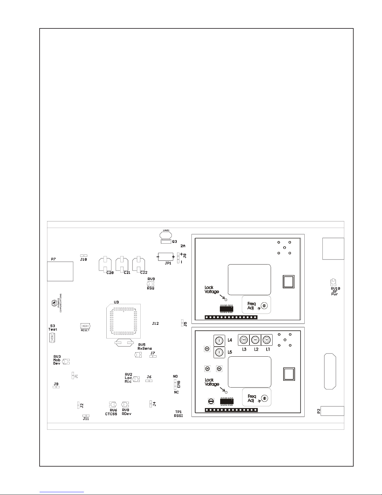
will be installed with. Refer to figure 1 for alignment points.
Dis-assemble the repeater by removing the two cap screws on the front panel; disconnect the front panel from
the main chassis by removing the 2 connectors. Remove the two cap screws from the rear panel and slide the main
circuit board out of the housing with the rear panel attached. Re-connect the front panel to the main PCB. Connect
one service monitor to the SVR-250 TNC jack and the other to the mobile antenna jack. Connect the cable from
the mobile radio to the SVR-250 (See figure 4 on page 16). Turn on the mobile and activate the SVR-250.
Adjust the repeater squelch control (RV9) so that the repeater COR led is off. Adjust the mobile so that the audio
is squelched.
SVR-250 VHF Transmitter
1. Transmitter Output: Push S3 and adjust RV10 for maximum. Confirm the SVR-250 RF Power out is at least
2W. Adjust RV10 for 250 mW.
2. Transmitter frequency: Adjust the TCXO on the Tx RF board for the transmit frequency.
3. Maximum deviation/lock tone deviation: If the SVR-250 is programmed for sub-audible encode, adjust RV6
(CTCSS) for minimum. Adjust RV8 (repeater deviation) for 80% deviation; adjust RV6 for total 95%
deviation (sub-audible and lock tone). If programmed for carrier squelch transmit adjust RV8 for 95%
deviation. Release S3.
4. Mobile COR: Measure the voltage at TP2 on the SVR-250 main PCB and record. Ensure the mobile COR
LED on the front panel is off. Set the mobile service monitor for the mobile receive frequency, 1mV RF output
and CTCSS modulation of 15% deviation. Measure the voltage again at TP2 and record. Ensure the mobile
COR LED on the front panel is on. The 2 voltages at TP2 must be at greater than 2.1VDC and less than 1.1
VDC.
5. RX audio sensitivity/CTCSS deviation: Set the service monitor connected to the mobile for the mobile receive
frequency and 1mV RF output. Modulate the signal generator with a 1kHz tone at 60% deviation and CTCSS
tone at 15% deviation. Ensure that the SVR-250 mobile COR and repeater PTT LED’s are on. If the
SVR-250 is programmed for sub-audible encode adjust RV5 on the SVR-250 main board for 75% deviation,
adjust for 60% deviation if carrier squelch transmit, as read on the service monitor connected to the SVR-250.
Turn the RF output from the mobile service monitor off and ensure that the SVR-250 mobile COR and repeater
PTT LEDs are off.
6. Local mic repeat: If the SVR-250 is programmed for local mic repeat, key the mobile local mic and inject an
audio signal into the local mic to produce 60% deviation on the service monitor connected to the mobile.
Confirm that the SVR-250 repeater PTT LED is on; adjust RV2 for 60% deviation as read on the service
monitor connected to the SVR-250. Unkey the mobile radio.
7. RF power out: Press S3 and adjust RV10 for the operating power output. Release S3.
Page 10
SVR-250 Service Manual
VHF Receiver
1. Receiver front end: Connect a DC voltmeter to TP1 on the SVR-250 main board. Set the service monitor
connected to the SVR-250 to the generate mode, receive frequency with a 1kHz tone and 60% deviation.
Adjust the RF output of the monitor for a 1VDC reading at TP1. Adjust L1-L5 on the RF board for a maximum
reading at TP1.
2. Repeater squelch: Adjust the service monitor RF output for .5μV. Adjust RV9 on the SVR-250 main board
so the repeater COR LED is just on. Decrease the service monitor RF output to .3μV and ensure that the
repeater COR LED is off.
3. Transmit audio output: Adjust the service monitor RF output for 1mV. Turn the CTCSS modulation on and
set for 15% deviation. Confirm that the repeater COR, CTCSS and mobile PTT LED’s are on. Adjust RV3
on the SVR-250 main board for 60% deviation as read on the service monitor connected to the mobile radio.
Turn off the CTCSS modulation of the service monitor connected to the SVR-250. Confirm that the repeater
CTCSS and mobile PTT LED’s are off.
4. Lock Tone Decode: Change the 1kHz tone modulation to the lock tone frequency. Confirm that the PRI LED
goes off after approximately .5 seconds.
Figure 1
Page 11
 Loading...