

Page 1
OPERATION MANUAL
Manual Tuning Stereo Radio Receiver
Digital Compact Disc Player with CD-R/RW Playback
Maximum Output 160W
Mechanical Detachable Front Panel
Electronic Preset Equalizer
Electronic Audio Control
CDR-36DX
English
DEAR CUSTOMER
Congratulations for your purchase!
Please read this manual carefully, and keep it for future reference.
If you need extra support, please visit www.pyramidcaraudio.com
Page 2
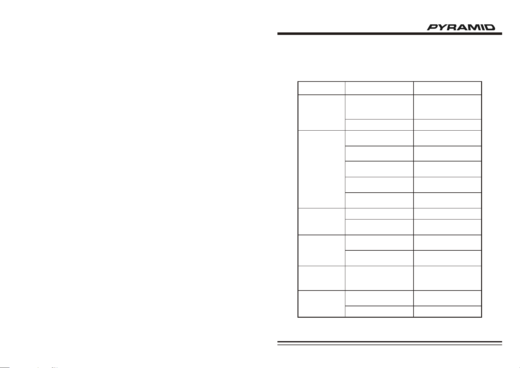
06 TROUBLESHOOTING
Before going through the check list, check wiring connection. If any of the presist after checklist
has been made, consult your nearest service dealer.
Symptom
No Power
CD Cannot Be
Loaded or Ejected
No Sound
So un d S ki pp in g
The Operation Keys
Do Not Work
Causes
The car ignition key has not
been switched on
The fuse is blown
A CD is already inside the
player slot
Inserting the CD in reverse
direction
The CD is extremely dirty or
defected
Temperature inside the car is
too high
Condensation
Volume is at minimum
Wiring is not properly
connected
The installation angle is more
than 30°
CD is extremely dirty or
defected
The built-in microcomputer is
not operating properly due to
interference
Solution
If the power supply is properly
connected to the car accessory
terminal, switch the ignition
key to ACC.
Replace a new fuse
Remove the CD from the player
and insert the new one
Insert the CD with the label
facing up
Clean the CD or try to play
a new one
Cool off until the ambient
temperature return to normal
Leave the player off for an
hour or so and try again
Adjust volume to desired level
Check wiring connection
Adjust the installation angle to
less than 30°
Clean the CD or try to play
a new one
Press the RESET button or
reinstall the front panel
properly
The Radio or
Automatic Selection
Does Not Work
The antenna cable is not
connected correctly
The signals are too weak
Connect the antenna cable
correctly
Select the station manually
Page 09
Page 3

05 SPECIFICATION
General
Power Supply Requirements:
Maximum Output Power:
Chassis Dimensions:
Tone Controls
Bass (at 100Hz):
Treble (at 100KHz):
Current Drain:
CD Player
Signal to Noise Ratio:
Channel Separation:
Frequency Response:
FM Radio
Frequency Coverage (MHz):
IF :
Sensitivity (S/N=30dB):
Stereo Separation:
DC 12V, Negative Ground
160W
178 x 165 x 50mm (W x D x H)
+10dB / -10dB
+10dB / -10dB
5 A
More than 60dB
More than 60dB
20Hz - 20KHz
87.5 - 108 (Europe)
65 - 108 (OIRT)
87.5 - 107.9 (U.S.A.)
10.7MHz
12dBμ
>30dB
TABLE OF CONTENTS
Thank you for buying this product!
Pl ease read th rough thes e instruct ions so you wi ll know h ow to i nstal l and
op era te your mode l properly. After you have finished rea din g the
instruction s, pu t the m awa y in a sa fe pl ace f or future reference.
01
Installation
Precautions
DIN Front-Mount (Method A)
DIN Rear-Mount (Method B)
02
Additional Information
Wire Connection Diagram
How To Install and Remove The Front Panel
03
General Operations
Front Panel Layout
General Operations
04
Radio & CD Operations
02
02 - 03
03
04
04
05
05 - 06
AM Radio
Frequency Coverage (KHz):
IF :
Sensitivity (S/N=20dB):
522 - 1620 (Europe/OIRT)
530 - 1710 (U.S.A.)
450KHz
32dBμ
Radio Operations
CD Operations
05
Specification
06
Troubleshooting
07
07
08
09
Page 01Page 08
Page 4

01 INSTALLATION 04 RADIO & CD OPERATIONS
PRECAUTIONS
Choose the mounting location where the unit will not interfere with the normal driving function
of the driver.
Before finally installing the unit, connect the wiring temporarily and make sure it is all connected
up properly and the unit and the system work properly.
Use only the parts included with the unit to ensure proper installation. The use of unauthorized
parts can cause malfunctions.
Consult with your nearest dealer if installation requires the drilling of holes or other
modifications of the vehicle.
Install the unit where it does not get in the driver's way and cannot injure the passenger if there
is a sudden stop. Like an emergency stop.
If installation angle exceeds 30° from horizontal, the unit might not give its optimum
performance.
30
Avoid installing the unit where it would be subject to high temperature, such as from direct
sunlight, or from hot air, form the heater, or where it would be subject to dust, dirt or excessive
vibration.
DIN FRONT-MOUNT (Method A)
Installing the unit
1. Dashboard
2. Holder
After inserting the holder into the
dashboard, select the appropriate tab
according to the thickness of the
dashboard material and bend them
inwards to secure the holder in place.
3. Screw
1
(Fig. 1)
2
3
RADIO OPERATIONS
BAND
Press BND button (10) to change bands as
below:
FM AM
SELECT STATION
Rotate TUNING knob (11) clockwise or
anticlockwise to adjust the frequency
upward or downward.
CD OPERATIONS
DISC PLAY
Gently insert a CD with the label side facing
up into the Disc Slot (16). The CD is then
automatically loaded into the unit and starts
playing with the first track of the disc. The
digital display will indicate the track number
and the time of the track.
EJECT
Press Eject button (15) to stop CD
playback and eject CD from slot. Receiver
switches to radio operation.
PAUSE CD
Press Play/Pause button (14) to
temporarily stop the playback. Press it again
to resume playback.
SKIP TRACKS
Press Track Forward button (17) or
Track Reverse button (18) to choose the
following track or the previous track. Track
numbers show on display.
LOCAL/DISTANT
Press the LOC/RPT button (12) to select
between local setting for reception of strong
station and distant setting for reception of
weak station when tuning.
MONO/STEREO
In FM band, press MON/INT button (13)
to select mono or stereo reception for radio
stations. You can sometimes improve
reception of distant stations by selecting
mono operation.
FAST FORWARD/FAST REVERSE
Hold Track Forward button (17) or
Track Reverse button (18) for several
seconds to fast forward or fast reverse.
Releasing the button to stop fast forward
and fast reverse playback.
REPEAT
Press LOC/RPT button (12) to
continuously repeat playing the current
track. Press it again to cancel the function.
INTRO:
PREVIEW ALL TRACKS
Press MON/INT button (13) to play first
several seconds for each track. Press it again
to stop intro and back to normal playback.
RANDOM:
RANDOM TRACKS PLAYBACK
Press and hold LOU/RDM button (8) for
several seconds to play all tracks in the
random order. Press it again to cancel the
function.
Page 07Page 02
Page 5

03 GENERAL OPERATIONS 01 INSTALLATION
SELECT MODE
Press SEL button (3) to change audio
mode through volume, bass, treble, balance
mode. Use VOL Up (4) and VOL Down (5)
button to adjust the selected mode. When
mode has not been adjusted for several
seconds, display returns to normal radio or
CD display.
VOL
BAL
(Volume)
OPT IONAL :
VOL BAS TRE BAL FAD
(Volume) (Bass) (Treble) (Balance) (Fader)
VOLUME
BAS
(Bass) (Treble) (Balance)
TRE
Adjust volume level by using VOL Up (4)
and VOL Down (5) buttons.
BASS
Press SEL button (3) one time. Adjust bass
level by using VOL Up (4) and VOL Down
(5) buttons.
TREBLE
Press SEL button (3) two times. Adjust
treble level by using VOL Up (4) and VOL
Down (5) buttons.
BALANCE
Press SEL button (3) three times. Adjust
sound balance between left and right
speakers by using VOL Up (4) and VOL
Down (5) buttons.
FADER (optional)
Press SEL button (3) four times. Adjust
sound balance between front and rear
speakers by using VOL Up (4) and VOL
Down (5) buttons.
MUTE
Press MUTE button (6) to mute down sound.
Press it again to release this mode and recover
previous volume level.
CD MODE/RADIO MODE
During CD operation, Press BND button (10)
to switch to radio mode. During radio operation,
when a compact disc is inserted in the Disc
Slot (16), Press Play/Pause button (14) to
switch to CD mode and start playing.
EQUALIZATION
Press EQ button (7) to turn to equalization
function and to select desired audio mode.
There are four kinds of modes as below:
EQ/OFF
CLASSIC
POP
ROCK
LIQUID CRYSTAL DISPLAY
The LCD (19) can show the current state of
the unit.
FLASHING LED
If the front panel is not on the main unit, LED
(20) will be flashing.
RESET BUTTON FUNCTION
RESET button (21) is placed on the housing
and must be activated with either a ballpoint
pen or thin metal object. The RESET button
(21) is to be activated for the following
reasons:
· Initial installation of the unit when all wring is
completed.
· All the function buttons do not operate.
· Error symbol on the display.
1
6
7
4
2
5
3
(Fig. 2)
1. Dashboard
2. Nut (5mm)
3. Spring Washer
4. Screw (5 x 25mm)
5. Screw
DIN REAR-MOUNT (Method B)
Installation using the screw holes on the
sides of the unit
1
2
4
5
3
2
5
8
(Fig. 3)
6. Strap
Be sure to use the strap to secure the
back of the unit in place. The strap can
be bent by hand to the desired angle.
7. Plain Washer
8. Fix the springs on each side.
Fastening the unit to the factory radio
mounting bracket.
1. Select a position where the screw holes of
the bracket and the screw holes of the
main unit become aligned (are fitted), and
tighten the screws at 2 places on each
side. Use either truss screws
(5 x 5mm) or flush surface screws (4 x
5mm), depending on the shape of the
screw holes in the bracket.
2. Screw
3. Factory radio mounting bracket
4. Dashboard or Console
5. Hook (Remove this part)
NOTE: If Press RESET button (21), the unit can't work yet, please use a cotton swab soaked in isopropyl
alcohol to clean the socket on the back of the front panel.
NOTE: The mounting box, outer trim ring, and half-sleeve are not used for method B installation.
Page 03Page 06
Page 6

02 ADDITIONAL INFORMATION 03 GENERAL OPERATIONS
WIRING CONNECTION DIAGRA M
HOW TO INSTALL AND REMOVE THE FRONT PANEL
INSTALLING THE FRONT PANEL
To install the front panel, insert the panel
into the housing and make sure the panel is
properly installed, otherwise, abnormalities
occurs on the display or some keys will not
function properly.
REMOVING THE FRONT PANEL
Press the release button and pull-off the
front panel, keep front panel into the case.
FRONT PANEL
FRONT PANEL LAYOUT
2
4
5
311
20
19
7
16
15
17
14
18
10
1
21
9
13
8612
GENERAL OPERATIONS
ON/OFF
Press POWER button (1) to turn on the unit. Press it again to turn off.
FRONT PANEL RELEASE
Press REL button (2) to detach the removable front panel
LOUDNESS
Press LOU/RDM button (8) shortly to reinforce the bass output.
SET THE CLOCK
Press DSP button (9) to change the display to clock display. Press it again to return to
previous display. In clock display, press and hold the DSP button (9) for several seconds until
the clock display flashes. Press Track Forward (17) button to change minutes or Track
Reverse (18) button to change hours.
RELEASE BUTTON
Page 05Page 04
 Loading...