

Page 1
~YRA..N\.\d
Oold
)czricz)
MODEL:906VL
Built
10
Band
With
For
12
in
FM
Antenna
Graphic
Scanning
Volts
D.C. Negative Ground
Booster
Equalizer
and
Night
System
Booster
Illumination
Only
Page 2
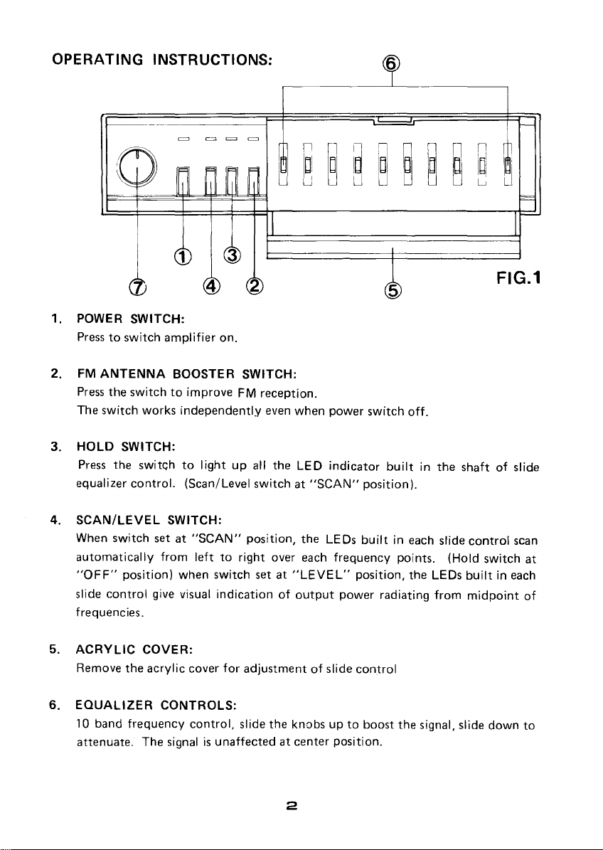
OPERATING
INSTRUCTIONS:
6
n
IDi
~
1. POWER
Presstoswitch
2.
FM
ANTENNA
Press
The
switch
3.
HOLD
Press
equalizer
4.
SCAN/LEVEL
When
automatically
"OFF"
slide
control
frequencies.
5.
ACRYLIC
Remove
SWITCH:
amplifier
BOOSTER
the
switchtoimproveFMreception.
works
SWITCH:
the
switchtolightupall the
control.
SWITCH:
switch
setat"SCAN"
from
position)
give visual
COVER:
the
acrylic
on.
SWITCH:
independently
(Scan/Level
lefttoright
when
switch
indicationofoutput
cover
for
adjustmentofslide
switchat"SCAN"
position,
set at
even when
LED
the
over each
"LEVEL"
power
switch
indicator
position).
LEOs
builtineach slide
frequency
position,
power
radiating
control
5
off.
builtinthe
points.
the LEOs
from
FIG.1
shaftofslide
control
(Hold
switch
builtineach
midpoint
scan
at
of
6.
EQUALIZER
10 band
attenuate. The signalisunaffectedatcenter
CONTROLS:
frequency
control,
slide
the
knobsupto
2
boost
position.
the
signal, slide
down
to
Page 3
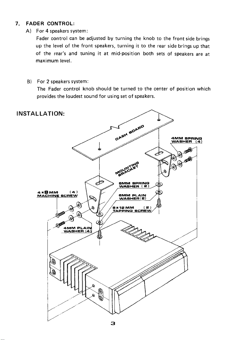
7. FADER CONTROL:
A)
For
4 speakers
Fader
up
of
maximum
B)
control
the
the
For
2 speakers
The Fader
provides
canbeadjustedbyturning
levelofthe
rear's
and
level.
control
the
loudest
INSTALLATION:
system:
front
tuningitat
system:
knob
speakers,
shouldbeturnedtothe
sound
for
turningitto
mid-position
using
setofspeakers.
the
knobtothe
both
front
side brings
the
rear side bringsupthat
setsofspeakers
centerofposition which
are
at
r;/
..
3
Page 4

ELECTRICAL CONNECTIONS:
for
4 Speaker System (4or8 ohm)
R.F.
OUTPUT
(TO CAR RADIO)
ANT
INPUT
~--1
+ B
G-=:O
1----------,
I
COMMON
I
SYSTEM
GROUND "
RADlOI
RI
GHT OUTPUT
PLAYER •
r-------------,
IFOR
LOW
IMP,
AUD10
IINPUT(Hl
L \
\
rr-"--;:~--=-:::l--,
(+)
II:
(-)
I
LEVER)
I
~
+El
:
GREEN
I GREEN J
~=~----ll
IIIGRAYIWHlT£
(INPUT)
WHlTE
REAR
FRONT
SPEA
SPEAKER
LEFT
KER
LEFT
RED
(INPUT)
---------"
REAR
RIGHT
SPEAKER
FRONT R1GHT
SPEAKER
,
,
,
,
,
,
,
,
,
,
Urr
L R
INPUT
,-------,
I
OUTPUT
I l R I
I I
I I
I I
, I
I
~
,0
~
I
4 I
10.:_
:
~ ~
'>
[r
W I
,~...J
1:r:3=
I w a I
~~
I
>--
It->o-
I«:::l
:
~~
L
I
I
I
,
I
I
I
I
I
,
I
I
I
:
--J
Page 5

for
2 Speaker
System(4ohm)
r~------------,
[FOR
LOW
IMP.
AUD10
\ +B--j11t=I------"=--.J
rr-"---~-::~l-
-l
II
I I
.=.:.~--l'
IIIGRAVIWHlTE
+ B c,-:;O
RIGHT
U!::!~~_~~~_L~::~~.~J
(+)
OUTPUT
(-)
r------------:
i
Sy~~~~ONRAGD~~~Np~AYER
!
I
GREEN
GREEN I
LEFT
(INPUT)
WHITE
A.F. OUTPUT
RED
(lNPUT)
SPEAKER
ANT
(TO
CAR RADIO)
INPUT
~--1
OND
RIGHT
--------,
SPEAKER
,
,
,
,
I
I
,
,
I
I
'tTB
L ,
INPUT
'-OUTPUTI
I L R I
I I
I I
: I
I I
I
~
I
I D I
I
~
:
11i~
I
:
~ ~
I
I > I
:~lj
:
1:I::3C I
I
~:;
:
1>-
_ I
I:~
i
I~::
:
L
..J
5
Page 6

SPECI
FICA
TlONS:
volt
..
..
..
"
12
Ground
150
Watt
more than
Input47kn
Low
Input
30Hz,
1KHz,
±
8A
60Hz, 120Hz, 250Hz, 500Hz,
10dB
5 dB
176
(W)
2KHz,
x40
Power Supply .
utput
O P
Speaker
Frequency Response. . . . . . . . 20 Hz - 20
SignaltoNoise
Input
Control Frequency . . . . . . . . . . . .
Control
Fuse
FM
Dimensions
ower .
Impedance.
Impedance High
Range.
Ant
Max. Sensitivity
(W
. . . . . . . . 4 ohm (4
Ratio.
. . . . . . . . . .
. . . . . . . . . . . . . .
x H x D)
CAUTION:
D.C.
x 2 Max.
ohm
- 8
KHz
60dB
100
n
(H) x
Nominal, Negative
ohm
allowable)
± 1
dB
4KHz,
154
8KHz,
(D)
mm
16KHz
1. The
2.
3. This equipment
4. To avoid the possibility
5.
unit
and the speaker
(chassis)
For best result, speakers shouldberatedtosafely handle the additional power
output
only. The
amplifier
supply) when installing and
Use
same
from
any speaker wire.
providedbythe
is
intended
useofvoltageorpolarity
should
highorlow
time.
be
level inputstothe equalizer. Both can-notbeconnected at the
willbedamagedifthereisa connet::tiontothe
unit
speakers
for
of
short-circuiting the
switched-off (preferably disconnected
wiring
with
low
power rating maybedamaged.
usein12V
the
DC negative ground electrical system
convertersisdiscouraged.
output
speakers.
B
stages
both
radio and
from
the
ground
the
power
Page 7

CARE AND MAINTENANCE
Your Pyramid 300 Watt Stereo 10-Band
Equalizer/Booster is
superior design and craftsmanship.
The following suggestions will help you
care for your equalizer/booster
it
can enjoy
I
I
(:j
'-I"'
for years.
Keep
booster
get wet, wipeitdry immediately. Liquids con-
tain minerals that can
corrode electronic circuits.
Use and store the equalizer/booster only
mal
ronments. Temperature
extremes can shorten
the life of electronic devices and distort or melt
plastic parts.
Handle the equalizer/
booster gently and care-
'
fully.
./
damage the circuit
boards and can cause
to work improperly.
an
example of
so
you
the equalizer/
dry,
Ifitdoes
in
nor-
temperature envi-
Dropping
it
can
it
Keep
booster away from dust
and dirt, which can
cause premature wear
of parts.
Wipe the equalizer/
)\
,I"',"
@
. . keepitlooking
booster with a damp
cloth occasionally to
not
cals, cleaning solvents,
or strong detergents to
clean the equalizer/
booster.
the equalizer/
new.
use
harsh chemi-
Do
7
Page 8

www.pyramidcaraudio.com
 Loading...