

Page 1
®
HIGH PERFORMANCE CAR AUDIO
MODEL 401EP
IN-DASH 4 BAND PARAMETRIC EQUALIZER
www.pyramidcaraudio.com
Page 2
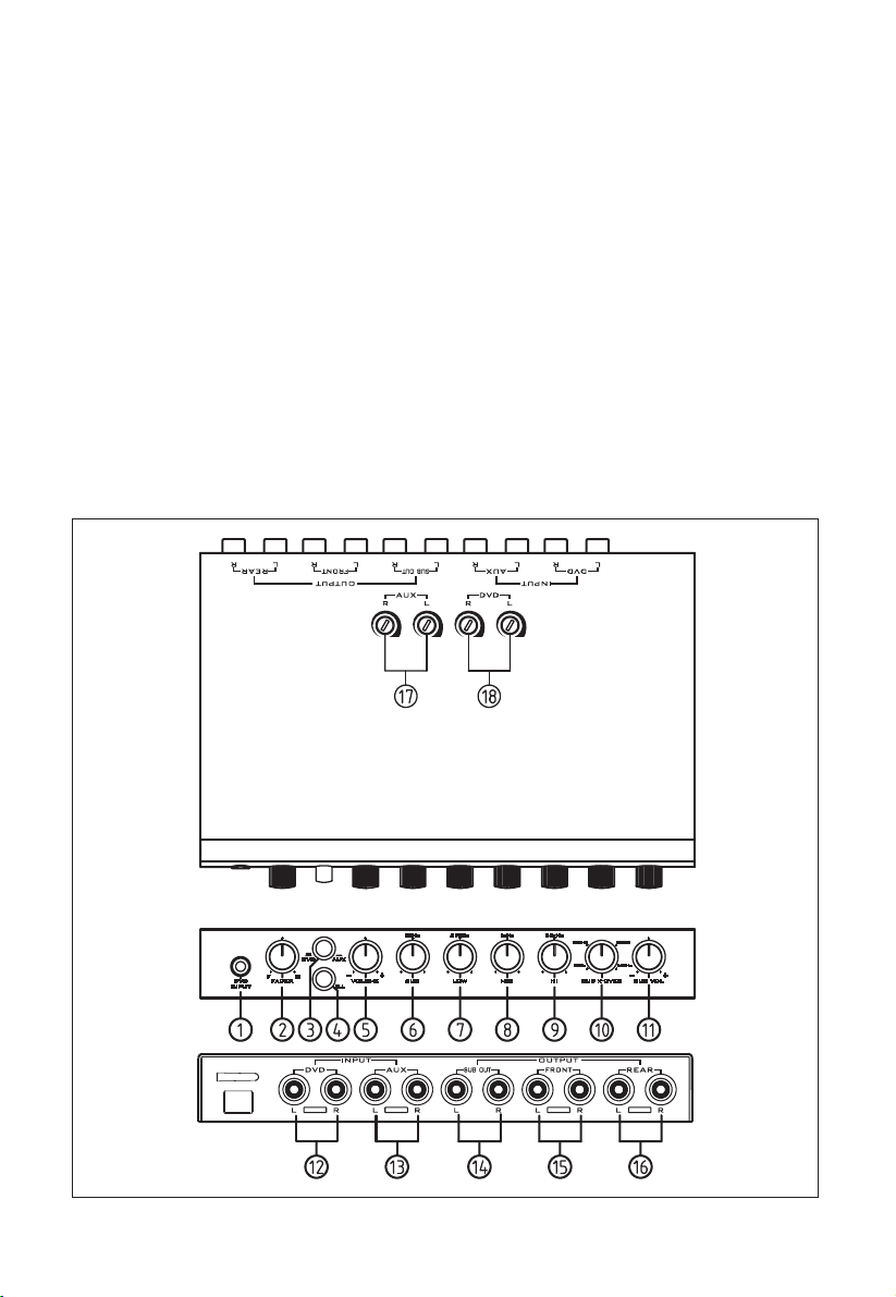
FEATURES:
1. 3.5MM DVD INPUT JACK
2. FADER CONTROL
3. DVD/AUX INPUT SELECTOR
SWITCH
4. BI-COLOR LIGHT ILLUMINATION
WITH SELECTOR
5. VOLUME CONTROL
6. SUB BAND EQUALIZER CONTROL
7. LOW BAND EQUALIZER CONTROL
8. MID BAND EQUALIZER CONTROL
9. HIGH BAND EQUALIZER CONTROL
CONTROLS:
10. SUB CROSSOVER FREQUENCY 30-250 HZ ADJUSTABLE
11. SUB OUTPUT VOLUME CONTROL
12. DVD INPUT PORT
13. AUX INPUT PORT
14. SUB OUTPUT PORT
15. FRONT OUTPUT PORT
16. REAR OUTPUT PORT
17. AUX INPUT GAIN ADJUSTMENT
18. DVD INPUT GAIN ADJUSTMENT
1
Page 3

OPERATION:
1. 3.5MM DVD INPUT JACK
Connects to the DVD source with
3.5mm plug cable.
2. FADER CONTROL
This control adjust the volume
between the front and rear speakers
in a 4 speaker system.
3. DVD/AUX INPUT SELECTOR
SWITCH
This switch selectors the DVD or
AUX input.
4. ILLUMINATION SELECTOR
SWITCH
This switch allows to select the color
of light illumination.
5. VOLUME CONTROL
This control adjusts the output level.
6-9. 4 BAND PARAMETRIC EQUALIZ-
ER CONTROLS
This four-band equalizer gives you
to control over the output levels at
various frequency.
10. SUB CROSSOVER FREQUENCY
30-250 HZ ADJUSTABLE
Lets you adjust the subwoofer
crossover frequency from 30 to 250 Hz.
12. DVD INPUT PORT
Connects the RCA cable to the output of DVD player.
13. AUX INPUT PORT
Connects the RCA cable to the output of auxiliary source.
14. SUB OUTPUT PORT
Connects the RCA cable to the subwoofer channel amplifier input.
15. FRONT OUTPUT PORT
Connects the RCA cable to the front
channel amplifier input.
16. REAR OUTPUT PORT
Connects the RCA cable to the rear
channel amplifier input.
17. AUX INPUT GAIN ADJUSTMENT
Allows you to adjust the left and right
channel input sensitivity level separately
to match the output level for AUX source
input.
18. DVD INPUT GAIN ADJUSTMENT
Allows you to adjust the left and right
channel input sensitivity level separately
to match the output level for DVD source
input.
11. SUB OUTPUT VOLUME CONTROL
This control adjusts output level of
subwoofer RCA jack.
2
Page 4

MOUNTING INSTRUCTION :
Signal Processor enclosure
Mounting Bracket
4x12mm
self-tapping screw (2)
4 mm spring
washer (2)
4 mm plain
washer (2)
4x6mmmachine screw (4)
dashboard
3
Page 5

ELECTRICAL WIRING DIRECTIONS
4
Page 6

SPECIFICATIONS:
4 Band Parametric . . . . . . . . . .Sub 50Hz, Low 210Hz, Mid 1KHz, Hi 20KHz
Boost/ Cut . . . . . . . . . . . . . . . . . . . . . . . . . . . . . . . . . . . . . . . . . . . . . .18dB
Crossover Frequency . . . . . . . . . . .Continuously variable from 40 to 400 Hz
Frequency Response . . . . . . . . . . . . . . . .20-20,000 Hz ( at ±3dB, 400mV)
Input Level, Front/Rear (for 400 mV Output) . . . . . . . . . . . . . . . . . . .200mV
Total Harmonic Distortion . . . . . . . . . .Less than 0.025% (at 400mV Output)
Output Impedance . . . . . . . . . . . . . . . . . . . . . . . . . . . . . . . . . . .1.2K Ohm
Single-to-Noise Ratio . . . . . . . . . . . . . . . . . . . . . . . . . . . . . . . . . . . . .85 dB
Separation . . . . . . . . . . . . . . . . . . . . . . . . . . . . . . . . . . . . . . . . . . . . .60 dB
Control Range . . . . . . . . . . . . . . . . . . . . . . . . . . . . . . . . . . . . . . . . .±12 dB
Current Drain . . . . . . . . . . . . . . . . . . . . . . . . . . . . . . . . . .200mA Maximum
Power Supply Voltage . . . . . . . . . . . . . . . .DC, 10-16 Volt Negative Ground
Dimensions (WDH) . . . . . . . . . . . . . . . . . . . . . . . . . . . .178 x 113 x 25 mm
5
Page 7

NOTES
 Loading...