

Page 1
U.S.A.
Y
AMIDR
POWER
STANDBY
MUTE
PHONES
PR-330A
INTEGRATED STEREO AMPLIFIER
INTEGRATED STEREO AMPLIFIER
INDIVIDUAL BASS/TREBLE CONTROL
OFFON
INDIVIDUAL BASS/TREBLE CONTROL
BASS
0
2
4
6
8
10
TREBLE
4
8
6
2
4
6
8
10 10
0
2
4
6
8
2
10
TAPE
100W+100W
POWERFUL AMPLIFIER SYSTEM
AUX
AV1/AV2
CD
REMOTE SENSORREMOTE SENSOR
PRESET EQPRESET EQ
TUNER
VOLUME
MIC MIC LEVELMIC LEVEL
EXTERNAL
EXTERNAL
PROCESSOR
PROCESSOR
MULTI-FUNCTION REMOTE CONTROLLED SYSTEM
MAXMIN
Page 2
PRECAUTIONS
Thank you for purchasing this HI-FI product. Taking time
to read these operating instructions carefully before use
will acquaint you fully with all its features and help ensure
optimum performance.
In order to simplify the explanation illustrations may
sometimes differ from the originals.
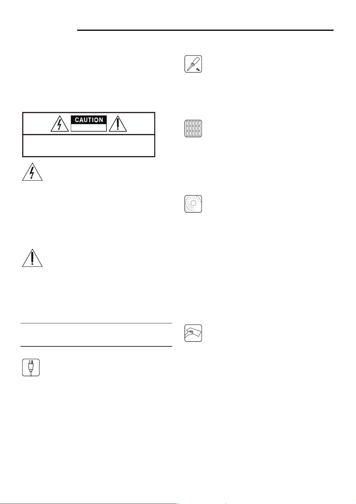
RISK OF ELECTRIC SHOCK
DO NOT O PEN
CAUTION: TO REDUCE THE RISK OF ELECTRIC SHOCK,
DO NOT REMOVE COVER(OR BACK)
NO USER-SERVICEABLE PARTS INSIDE.
REFER SERVICING TO QUALIFIED SERVICE PERSONNEL.
The lighting flash with arrowhead symbol,
within an equilateral, is intended to alert the user
to the presence of uninsulated “dangerous
voltage” within the product’s enclosure that may
be of sufficient magnitude to constitute a risk of
Do not remove the case and bottom panel
Any inspections or adjustments inside the unit
may lead to malfunctions and electric shocks.
Do not touch any of the inside parts.
Do not block the ventilation holes
Do not block the ventilation holes on the top of
the unit by placing records or other objects over
them. This will increase the inside temperature
may lead to a failure or malfunction.
Installation precautions
Do not install the unit in any of the following
electric shock to persons.
The exclamation point within an equilateral
triangle is intended to alert the user to the
presence of important operating and maintenance
(servicing) instructions in the literature
accompanying the appliance.
WARMING: To prevent fire or shock hazard, do not
expose this appliance to rain or moisture
Power plug
When disconnecting the power cord from the
power outlet, always take hold of the plug, and
not the wire, and pull free. Never connect or
disconnect the power plug with wet hands since
you may receive an electric shock.
Remember to disconnect the power plug from
the power outlet when you do not intend to use
the unit for a prolonged period of time.
locations since this may result in deterioration
in performance of malfunction:
* Locations exposed to direct sunlight or near objects
radiating heat such as heating appliances.
* Locations exposed to moisture or humidity.
* Locations with poor ventilation exposed to dust and
dirt.
* Locations which are unstable and not perfectly flat or
which are susceptible to vibration.
Do not wipe with thinners
Wipe the panels and case from time to time
with a soft cloth. Using any kind of thinner,
alcohol or volatile liquid will mar the surface,
cause blotching on the exterior and erase the
markings and should therefore be avoided. Do
not use insecticide sprays in the vicinity.
1
Page 3
CONNECTIONS FOR INTEGRATED STEREO AMPLIFIER
Refer to page 4 the connection diagram as you read the following.
Connection precautions
When connecting, either disconnect the power plug
from the power outlet or turn off the unit’s power
using the POWER switch.
Check the left and right channels and connect properly
(Left to L and Right to R).
Insert the plugs securely. Improper connection can lead
to the generation of noise.
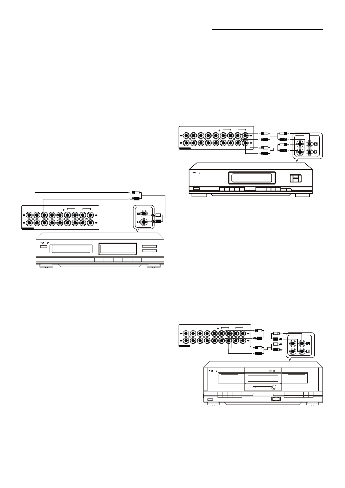
Compact disc player
Connect the CD terminals to the OUTPUT terminals on the
compact disc player using the pin-plug cord.
TAPE
CD AUX PLAY REC
AV1 AV2
TUNER
L
R
AUDIO
AMI
EQ
PLAY REC
L
R
OUTPUT
Playback connections: Connect the TAPE PLAY
terminals to the output (LINE OUT) terminals on the
cassette deck using the pin-plug cord.
TAPE
EQ
TUNER CD AUX PLAY REC
L
R
AUDIO
AV1 AV2
AMI
PLAY REC
L
R
LINE
(IN)REC PLAY(OUT)
PROCESSOR terminals
These terminals are used to connect a graphic equalizer or
sound processor. They also come in handy for connecting
an AV (audio/video) selector unit.
CD/AUX terminals
These terminals have an electrical performance which is
equivalent to that of the CD terminals and the TUNER
terminals which means that they can be used as the audio
output terminals for a video disc player or TV tuner.
Connect these terminals to the OUTPUT terminals on the
component using the pin-plug cord.
TAPE Deck
Recording connections: Connect the TAPE REC
terminals to the input (LINE IN) terminals on the tape deck
using the pin-plug cord.
Use pin-plug cords to connect the REC terminals to the
INPUT terminals on the selected component and also to
connect the PLAY terminals to its OUTPUT terminals.
TAPE
TUNER CD AUX PLAY REC
L
R
AV1 AV2
AUDIO
AMI
A
EQ
PLAY REC
L
R
(IN)REC PLAY(OUT)
B
OUTPUT
2
Page 4

CONNECTIONS
Speaker systems
Connect the speaker systems to the SPEAKERS terminals
on the rear panel of the unit with the speaker cords.
When viewed from the front (the listening position), the
speaker mounted on the left should be connected to the L
terminals, and the speaker mounted on the right should be
connected to the R terminals. Be sure to connect the
polarities of the speaker systems and the SPEAKER
terminals correctly (+ to +, - to -). If the polarity of one of
the speaker systems is connected improperly, sound in the
central area between the speakers will appear to be missing,
and the position of the instruments will not be clear,
resulting in a loss of stereo directionality; so take care
when connecting.
* When connecting, do not allow the conductor of the
speaker cords to be exposed from the terminals and come
into contact with other terminals.
Tuner
Connect the TUNER terminals to the OUTPUT terminals
on the tuner using the pin-plug cord.
TUNER CD AUX PLAY REC
L
R
AUDIO
AV1 AV2
AMI
EQ
PLAY REC
L
R
OUTPUT
TAPE
Front Left
Listening Position
Front Right
3
Page 5

CONNECTION DIAGRAM
TU
TU
AMP
REMOTE S YSTEM
TO AMP
ANTENNA
FM AM
75
Ω
EQ
REMOTE SYS TEM
EQ TAPE TUNER
TUNER CD AUX PLAY REC
L
R
AUDIO
CD
AV1 AV2
CD
VOLTAG E S E L E CT O R
220~230V110~120V
50Hz
OUTPU T
Loop
RIGHT LEFT
TAPE
EQ
PLAY REC
OUTPUT
L
L
_
R
60Hz
REMOTE SYST EM
_
TO AMP
INTEGRATED CIRCUIT
AC 220V - 230V ~50Hz
INTEGRATED CIRCUIT
AC 220V - 230V ~50Hz
INTEGRATED CIRCUIT
AC 220V - 230V ~50Hz
RISK OF EL ECTR IC SH OCK
TUNER
INTEGRATED CIRCUIT
POWER CONSUMPTION: 7W
VOLTAGE SELECTOR
110~1 20V
DO NOT OPEN
60Hz
110~120V
VOLTAGE SE LECT OR
220~230V
110~120V
220~2 30V
50Hz
VOLTAGE SE LECTO R
60Hz 50Hz
50Hz
60Hz
+R- +L-
220~230V
VOLTAGE SELECTOR
DC
LINE
(IN)REC PLAY(OUT)
REMOT E SY STE M
TO AMP
110~120V
220~230V
60Hz 50Hz
CASSETTE DECK
INTEG RATE D C IRCU IT
4
Page 6

PANEL INFORMATION
1
AMI
ON OFF
100W+100W
POWERFUL AMPLIFIER SYSTEM
18
17
1. POWER SWITCH
Power is supplied to the amplifier when this switch is depressed and
the power is switched off when the switch is released.
2. INDICATOR DISPLAY
Press either TAPE, AUX, AV1/AV2, CD or TUNER, the relative
indicator will be grown.
3. REMOTE SENSOR
Work with the remote control.
4. PRESET EQ
Press this button to select among ROCK, JAZZ, DISCO, CLASSIC
and FLAT when playing.
5. VOLUME CONTROL
This is used to control the sound heard from the speakers or through
the headphones. The volume will increase or decrease as the control
is rotated clockwise or counterclockwise..
6. EXTERNAL PROCESSOR
When using external processor, press this button.
7. MIC LEVEL VOLUME
Adjust the MIC LEVEL by rotating MIC LEVEL VOLUME knob.
8. MIC JACK
Inserting Microphone if using.
9. TUNER
This switch is pressed when you wish to listen to the radio
broadcasts from the tuner connected to the TUNER terminals.
10. CD
This switch is pressed when you wish to listen to the compact disc
player connected to the CD terminals.
16
15
14
13
12
2
11
10
11. AV1/AV2
Press this button when playing AV1/AV2 source. Press once for AV1,
press again for AV2.
12. AUX
Press this button when playing AUX source.
13. TAPE
This switch is pressed when you wish to listen to the cassette deck
connected to the tape terminals.
14. TONE CONTROL TREBLE VOLUME
The treble sound is emphasized when the TREBLE knob is rotated
clockwise from its “0” position while it is attenuated when the knob
is rotated counterclockwise.
15. TONE CONTROL BASS VOLUME
The bass sound is emphasized when the BASS knob is rotated
clockwise from its “0” position while it is attenuated when the knob
is rotated counterclockwise.
16. PHONES JACK
This is the jack for headphones. Connect the plug on the stereo
headphones for private listening.
Adjust the volume so that it does not hurt your ears when using the
headphones.
If you do not intend to use your headphones, always ensure that
you unplug them.
17. MUTE
Press this button to mute the sound, if resume, press it again to
un-mute or use the main volume control.
18. REMOTE STANDBY INDICATOR
3
9
4
5
6
8 7
The Power Amplifier is in remote standby state if the
remote standby indicator is lighted.
5
Page 7

OPERATING PROCEDURES
Before starting operation
Check that the controls have been set to the following positions before commencing operation
Rotate the VOLUME control counterclockwise as far
as it will go and set it at the “0” minimum volume
position.
Set the BASS and TREBLE tone controls to the “0”
(center) position.
Set the processor switch so that the indicator is off.
After these checks, press the POWER switch to turn on
the power.
If you find a remote standby indicator is lighted, the power
amplifier is in remote standby mode.
(a) Press the power switch off and press it once again after
the remote standby indicator is off.
(b) Using the remote control to switch on the power.
Playing a program source
1.Press the desired input selector button to select the
program source which you wish to listen to.
To listen to radio broadcast: Press the TUNER button.
2.Operate the program source unit.
3.Gradually turn the VOLUME control clockwise until the
desired volume level is obtained.
4.To adjust the tone quality, adjust the BASS and TREBLE
control.
* When you wish to use headphones, insert the plug of the
headphones into the PHONES jack.
RECORDING TAPE
A record, compact disc, broadcast of the program source of
a component connected to the line terminals can be
recorded by the tape deck connected to the TAPE recording
(REC) terminals.
1.Select the input selector switch corresponds to the
program source AUX, AV1/AV2, CD, TUNER that is to be
recorded.
2.Start playing the program source.
To listen to a compact disc: Press the CD button.
To listen to a component connected to AV terminals: Press
the AV1/AV2 button.
Note: Press once for AV1, press again for AV2.
To listen to a tape: Press the TAPE button
To listen to a component connected to the AUX terminal:
Press the AUX button.
VOLTAGE SELECTOR
Use this switch to
select the proper
Voltage for your region
L
R
AUDIO
TUNER CD
REMOTE SYSTEM
EQ TAPE TUNE R
AV1 AV2
CD
AUX PLAY REC
RIGHT LEFT
RIGHT LEFT
TAPE
PLAY REC
L
EQ
L
_
R
SPEAKERS6~8
Ω
_
INTEGRATED CIRCUIT
AC 220V~50Hz/110V~60Hz
V OLTA GE S ELE CTO R
110~120V
60Hz
220~230V
50Hz
3.Operate the tape deck and press the “REC” key.
*The volume, Tone and other controls have no effect on
the recording level or sound quality of the signals being
recorded even they are operated.
6
Page 8

OPERATION
REMOTE CONTROL
2
3
4
6
AMI
REMOTE CONTROL
PR-330A
7
(1) Power Button
(2) AM/FM Selector/Memory Scan/Hold
(3) Volume Control Key (+ -)
(4) Equalizer Sound preset
(5) Equalizer User Preset
(6) CD Control Key
* STOP (■)
* CLOSE/OPEN (
* PLAY/PAUSE (
* BACKWARD (
* FORWARD (
)
)
)
)
(7) Function Keys:
* TUNER
* AUX
* TAPE
* AV1/AV2
* CD
Remote Controlling Instructions
The remote control box can directly control majority of
system functions of HI-FI SYSTEM. The functions include
power control of the whole system, Volume control, sound
field control, CD operation control, Tuner operation
control and also source control function. This remote
controller may not function properly if an obstacle is
located between it and the receiving unit, or if the remote
controller is held at an improper angle with respect to the
receiving unit.
Battery Installation
Remove the rear cover of the remote controller by sliding it
backward. Install two AA (1.5 V) size batteries, while
observing the correct polarity [match the (+) and (-) signs].
Sound Field Control Operation
* Press the power button to connect to electric current.
* Use EQ Sound Mode key to select the sound mode
decided.
Each time the button is pressed, the mode changes as
follows:
ROCK → JAZZ → DISCO → CLASSIC → FLAT
* Use User Mode key to select the sound mode decided.
Each time the button is pressed, the mode changes as
follows:
[ A]
[ B] [ C] [ D] [ E]
**Note** Press the key one by one.
TUNER OPERATION BUTTONS
When the function switch is set to Tuner side:
* Press BAND keys for selecting AM/FM channel.
* Memo Scan: Press to scan the stations (0-9) stored in the
station memory.
* Memory Hold: After pressing Memory Scan key, Tuner
will scan through station (0-9). When your desired
station is reached, press MEMORY HOLD to hold it.
CD OPERATION BUTTONS
CD control buttons carry same functions as in the player.
* ( ■ ): STOP
): CLOSE/OPEN
* (
* (
* (
* (
): PLAY/PAUSE
): BACKWARD TRACK SEARCH
): FORWARD TRACK SEARCH
OTHER
* Sound source can be changed directly by pressing
TUNER, AUX, TAPE, AV1/AV2, CD button.
* Volume level can be adjusted by pressing VOL “-“ or
“+” keys.
**Note** Exhausted batteries may reduce the level of
sensitivity of the controller.
7
Page 9

SPECIFICATIONS
Power output
Min. RMS, both channels driven, from 40-20 kHz, with no more than 0.1% total harmonic distortion.
30 watts per channel into 6 ohms.
Load Impedance…………………..6 ohms
Total Harmonic Distortion………less than 0.05% at 1/2 rated RMS power output.
Frequency response (at 1 watt)…..20 to 20 kHz, + 1 dB, -2dB
Input sensitivity and impedance (at 1 kHz for rated power
output)
TUNER, TAPE PLAY………..250 mV/47 kohms
Output level (1 kHz)
TAPE REC……………………250 mV into 47kohms
Signal to noise ratio (short-circuit, A-network)
TUNER, TAPE PLAY….70 dB
Power requirements
Power voltage…….220V--230V--50Hz
For U.K………240V, 50Hz
For U.S.A & Canada…..110V, 60 Hz
Power consumption……watts VA Rated
Watts maximum
Dimensions………..420 x 135 x 230mm (W x H x D)
Weight………………6.2 Kg
Design and specifications for subject to changes without notice for improvements.
8
 Loading...