

Page 1

congratulations...
On your purchase of a Pyramid Signature Series
amplifier. This amplifier extends the pyramid
tradition into a totally new series of amps, designed
from the ground up to deliver the power,
performance and flexibility the modern car audio
enthusiast demands.
When you check the list of features offered by
the PB744,PB844 and PB1644, you’ll know you
made the right choice with a Pyramid Power
amplifier.
23
precautions
Do not operate the am plifier when it is unmounte d,
Attach all audio sy stem components securel y within
the automobile to p revent damage, especial ly in an
accident.
Do not mount this amp lifier so that the wire conne ctions
are unprotected , or in a pinched condition, or l ikely to be
damaged by nearby o bjects.
If you need to replac e the power fuse, do so only with a f use
identical to that s upplied with the amplifie r. Using a fuse of a
different type or rating may result in damage t hat isn’t covered
in the manufactur er’s warranty.
.
Before making or br eaking power connection s in your system,
disconnect the ve hicle battery. Confirm th at your head unit or
other equipment i s turned off while connecting the input jacks
and speaker termi nals.
notes
Page 2

general features
2
features and speifications
1
3- 4
24
2ch amp PB744
5- 6
4ch amp PB844
7- 8
4ch amp PB1644
electrical connections
9
4ch amp PB1644
stereo input connections
2CH amp PB744
13
mono input connections
2CH amp PB744
2/4 channel input connections
4CH amp PB844 PB1644
10
2ch amp PB744
speaker connections
17-18
4CH amp PB844
mounting and installation
23
protection circuitry and troubleshooting
precautions
If thi s occur s ,care fully i nspec t the sys tem to
dete rmine t he sour ce of the p roble m.
When t he prot ectio n circu it is act ivate d by any
of the se cond ition s, the Pr otect ion LED w ill be
illu minat ed.
If the s hutdo wn was a re sult of a t herma l overl oad
cond ition , allow t he ampl ifier to cool down be fore
atte mptin g to rest art it.
If the s hutdo wn was a re sult of a n input o verload,
or spe aker sh ort cir cuit, b e sure to c orr the
cond ition b efore r estar ting.
The am plifi er can be r estar ted by tu rning the
remo te powe r OFF and t hen ON ag ain.
No out pu t.
Chec k bo th i n- line and buil t- in f us es. Both the +1 2V a nd t he Remote ter mi na ls
must h av e +1 2V r eferenced t o ch as si s ground.
Conf ir m th at a ll terminal s tr ip c on nections ar e se cu re and tight.
Conf ir m th at t he audio sign al s ou rc e(car radio , eq ua lizer, etc.) I s co nn ec ted
and is s up pl yi ng output sig na l. To ch ec k if t he a mp is supplyi ng s ig na l, unplug
the ca bl es f ro m the signal so ur ce (b ut leave them p lu gg ed into the amp ).
Brie fl y ta p th e center pin of e ac h of t he d isconnect ed R CA pl ugs with your f in ge r.
This s ho ul d pr oduce a noise )f ee db ack) in you r sp ea ke rs.
Only o ne c ha nn el works.
Conf ir m th at a ll terminal s tr ip c on nections ar e se cu re and tight.
If the a bo ve s te ps fail to impr ov e or c le ar noise inte rf er ence, the sys te m
shou ld b e ch ec ked by a profes si on al m obile aud io i ns ta ller.
If you a re u si ng t he Low Level RC A inp ut , r ev erse the inpu t pl ug s at the
ampl if ie r( i.e.,swit ch t he L with the R) . If t he c ha nnels which i s si le nt switches
to the o th er s id e, the proble m is e it he r in the head uni t/ ot her source or t he
conn ec ti ng c ables.
Weak output.
If the n oi se i s a “c licking” or “ po pp in g” noise whos e ra te f ollows the en gi ne
spee d, t hi s us ually means t ha t th e ve hicle is equi pp ed w ith resisto r sp ar k
plug s an d wi re s, or that the ig ni ti on i s in need of serv ic e.
Nois e in t he a ud io.
Read ju st t he I nput Level Co nt ro l( s) to better su it t he i nput signal .
If the n oi se i s a “w hine” whose p it ch f ol lows the engi ne s pe ed, confirm t ha t
the am pl if ie r and any other s ig na l so urces(hes d un it , etc.) Are prop er ly g ro und.
Chec k th e Ba la nce control o n th e he ad u nit(or othe r so ur ce) to verify t ha t it
is set t o it s mi dp oint.
Chec k th e ro ut ing of the spea ke r an d in put wires to ma ke s ur e they are not
adja ce nt t o wi re which inte rc on ne ct lights and o th er a ccessorie s.
mono input connections
4CH amp PB844 PB1644
4CH amp PB844
19-20
1
22
2ch amp PB744
11
4ch amp PB844
12
14
15
16
21
22
The bu ilt-i n prote ction c ircui try in the Pyramid
Sign ature a mplif iers wi ll disable the ampl ifier i f it
sens es an inp ut over load, a s peaker short
circ uit, or e xtrem e tempe ratur e condi tions.
No out pu t.
Conf ir m th at a ll terminal s tr ip c on nections ar e se cu re and tight.
table of contents
protection
circuitry
troubleshooting
Page 3

2
23
.
.
400 Wa tts×4 Out put
.
.
.
.
.
.
.
.
.
.
.
.
.
.
.
.
.
Variabl e Hi/ Lo Elec troni c Cross over Ne twork
.
Variabl e Hi/ Lo Elec troni c Cross over Ne twork
.
Variabl e Hi/ Lo Elec troni c Cross over Ne twork
Variabl e Bas s Boost (0-+1 8dB@6 0Hz)
.
Variabl e Bas s Boost (0-+1 8dB@6 0Hz)
.
Variabl e Bas s Boost (0-+1 8dB@6 0Hz)
Variabl e Inp ut Leve l(Gai n)Con trol
.
Variabl e Inp ut Leve l(Gai n)Con trol
.
Variabl e Inp ut Leve l(Gai n)Con trol
Rem ote Turn o n/Off
.
Rem ote Turn o n/Off
.
Rem ote Turn o n/O ff
RCA In put s
.
RCA In put s
.
RCA In put s
. .
Pow er ON LED I ndica tor
.
Pow er ON LED I ndica tor
.
Pow er ON LED I ndica tor
LED P rotec tion In dicat or
.
LED P rotec tion In dicat or
.
LED P rotec tion In dicat or
S/N R atio: > 95dB
THD : <0.04 %
The rmal Pr otect ion
Ove rload P rotec tion
Sho rt Circ uit Pro tecti on
Ant i-Thu mp Turn- On
.
.
.
.
.
.
S/N R atio: > 95dB
THD : <0.04 %
The rmal Pr otect ion
Ove rload P rotec tion
Sho rt Circ uit Pro tecti on
Ant i-Thu mp Turn- On
.
.
.
.
.
.
S/N R atio: > 95dB
THD : <0.04 %
The rmal Pr otect ion
Ove rload P rotec tion
Sho rt Circ uit Pro tecti on
Ant i-Thu mp Turn- On
For this reason,
Your new Pyramid Signa ture Series amplifier com es complete with required mounting hardware.
When determinin g a suitable location in your v ehicle for the amp, please re member that it is a highpower electroni c device capable of generat ing high heat.
always choose a loc ation in your vehicle w hich has low vibratio n,
About power fuses:
Be sure to mount the am p
Mark the location f or the mounting screw h oles by positioning th e amp where you
wish to install
Then
mounting surfac e for the mounting screws and i nsert them. Tighten the screws securely.
Before attempti ng to drill the mountin g holes, take note of any w ires, lines or otherdevices
in your vehicle which may be located behin d the mounting surfac e!
Use at least 8 gauge wi re for power and ground conne ctions.
Wire the amplifie r directly to the car battery.
For the ground conn ection, use the shortest po ssible wire to a good chassis ground point.
Wire the Remote con nection to the auto start lead of your head unit, equalizer or power antenna.
adequate
in such a manner as
ventilation, a minimum of dust, and no moisture.
to allow reasonab le airflow over the cooling f ins.
it and use a scribe (or o ne of the mounting screws) in serted in each of the mounting holes to mark
the mounting surf ace for the mounting surface. If the mounting surf ace is carpeted, measure th e
hole centers and ma rk with a felt tip pen.
drill pilot holes i n the
When making elect rical connections t o your amplifier, please observe the following:
100 0 Watts×4 Ou tput
800 Wa tts× 2 Bri dged Ou tput (4 00W×2+ 800W×1) 200 0 Watts× 2 Br idged O utput ( 100W×2+20 00 W×1)
general features
PB744
PB844
PB1644
21
High Performance 1000Watt 2 channel
Bridgeable MOSFET Amplifier
High Performance 1600Watt 4 channel
Bridgeable MOSFET Amplifier
High Performance 4000Watt 4 channel
Bridgeable MOSFET Amplifier
500 Wa tts×2 Out put
.
.
.
.
100 0 Watts×1 Br idged O utput
.
.
.
.
.
.
.
.
.
.
.
.
.
.
.
.
.
.
.
.
.
.
.
.
.
. .
.
.
.
.
.
.
.
.
.
.
.
.
.
.
.
.
mounting and installation
Be sure to mount the am p
by positioning th e amp where you
wish to install
in such a manner as
Pyramid Signatu re Series amplifiers feat ure built-in fuse systems. These fuses protect both the
amplifier and the e lectrical system in your ve hicle from fault conditions. If you ever need to rep lace
the fuse in your Pyra mid Signature Series amp, u se a fuse of exactly the sa me type and rating. A
different type o r rating of fuse may result in da mage or fire.
Mul tiFun tion VF DMul tiFun tion VF D Mul tiFun tion VF D
Page 4
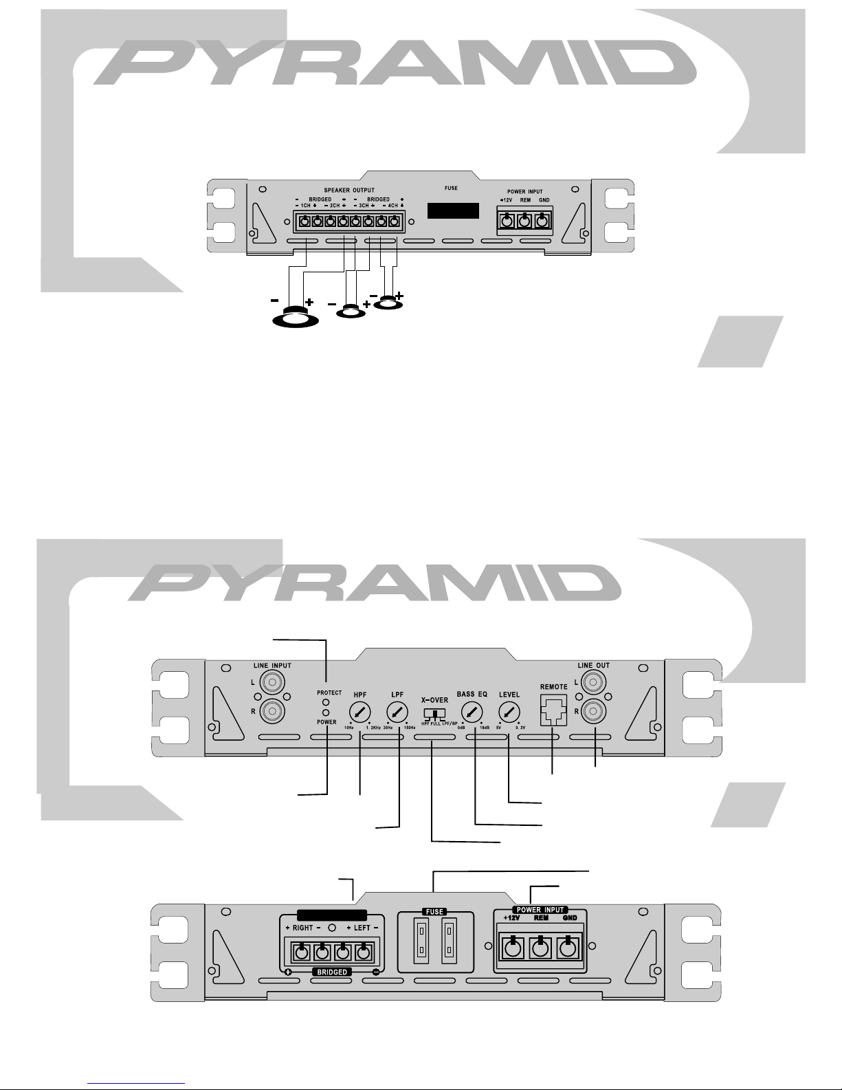
PB1644
speaker connections
4ch amp PB1644
2CH Bridged Output Mode With Subwoofer Output
MINIMUN
SPEAKER
IMPEDANCE
4OHMS!
SUBWOOFER
L
SPEAKERS
R
20
PB744
PB1217
protection LED
low level inputs
power LED
high pass frequency control
low pass frequency control
speaker connections
SPEAKER OUTPUT
features and controls
2ch amp PB744
output level
remote bass boost
input level control
bass boost level
crossover mode selector
power fuse
power terminals
3
Page 5
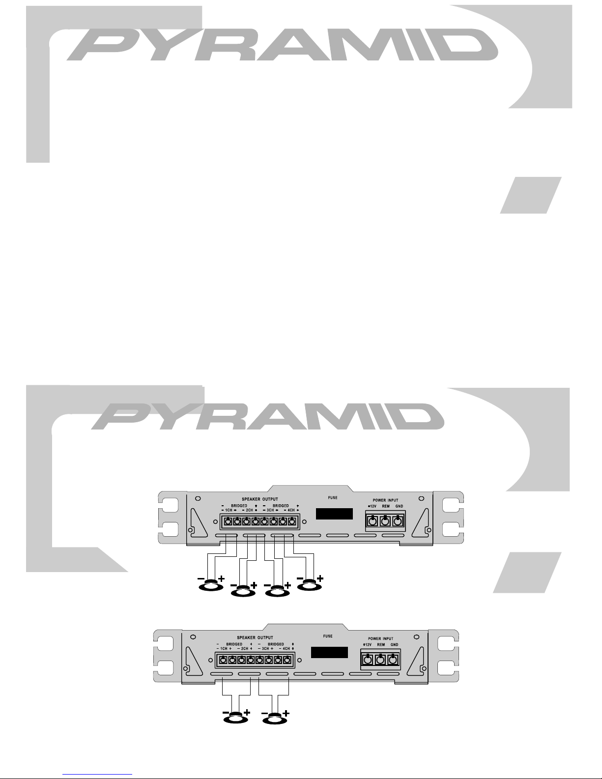
features and specifications
2ch amp PB744
crossover mode selector
input level control
low pass frequency control
high pass frequency control
bass boost level control
low level inputs
remote bass boost
power LED
protection LED
power fuse
power terminals
connections
speaker
when used with normal, full range systems, set this switch to “FULL”. If
you wish the internal crossover to power a driver of specific frequency
range , use the “LOWPASS” or “HIGHPASS” settings.
use this control to match the outputs of you head unit to the amplifier.
Starting with
the amp level control until distortion begins to occur, and reduce slightly
from this point.
when the crossover selector switch is in “low pass” mode, this control
sets the upper frequency limit for audio program sent to the speakers.
when the crossover selector switch is in “high pass” mode, this control
sets the upper frequency limit for audio program sent to the speakers.
this control permits
approximately 18 dB.
this amp features gold-plate RCA input jacks for high impedance input.
Use these with car stereo output which uses RCA-type connector cables.
Plug in the Remote Bass Control wire in here.
this indicator is illuminated when power is applied.
this indicator is illuminated when built-in protection circuitry is
the fuse protects the amplifier and your car’s electrical system from short
circuit conditions.
use these connectors to deliver power, ground and remote turn-on control
to the amplifier.
these terminals are 14K gold plated to guarantee high conductivity and
minimum signal loss.
your head unit set at about the 2 o’clock position, increase
adjustment of the bass level up to an increase of
activated.
output [email protected] DC, 1KHz
RMS Power @ 4 ohms
RMS
Power @ 2 ohms
Maximun Power
frequency response
power supply voltage
matching speaker impedance
maximum current draw
dimensions(W×H×L)
Output
input impedance
low level inputs
high level inputs
input sensitivity
low level inputs
stereo mode
bridged mode
mm
inches
50Wa tt s×2
100Watts×2
250Watts×2
10Hz-70KHz
10K Ohms
100 Ohms
200 mV
14.4V DC Neg.Ground (10.5-16V)
2-4 Ohms
4-8 Ohms
15A×2
292×48×251
11.7×1.92×10.0
4
PB1644
4CH Output Mode
L
FRONT speaker
Bridged Dual Mono Output Mode
L
speaker
speaker connections
4ch amp PB1644
R
L
R
REAR speaker
MINIMUN
SPEAKER
IMPEDANCE
4OHMS!
R
19
Page 6
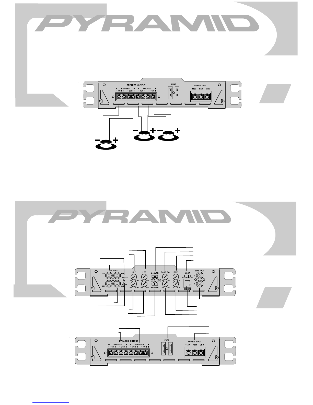
PB844
speaker connections
4ch amp PB844
2CH Bridged Output Mode with Subwoofer Output
R
SUBWOOFER
L
speakers
18
MINIMUN
SPEAKER
IMPEDANCE
4OHMS!
PB844
CH1/2 low pass frequency control
CH1/2 high pass frequency control
protection LED
CH1/2 input level control
CH3/4 input level control
power LED
CH3/4 high pass frequency control
CH3/4 low pass frequency control
CH3/4 crossover mode selector control
CH3/4 speaker connections
CH 1/2speaker connections
features and controls
4ch amp PB844
CH1/2 crossover mode selector switch
CH1/2 bass boost level control
CH1/2 level inputs
2/3/4 channel selectorl switch
output level
remote bass boost
CH3/4 level inputs
CH3/4 bass boost level control
power fuse
power terminals
5
Page 7
crossover mode selector
low pass frequency control
high pass frequency control
PB844
bass boost level control
input level control
low level inputs
high level inputs
power LED
protection LED
power fuse
power terminals
speaker connections
features and specifications
4ch amp PB844
when used with normal, full range systems, set this switch to “FULL”. If
you wish the internal crossover to power a driver of specific frequency
range , use the “LOWPASS” or “HIGHPASS” settings.
when the crossover selector switch is in “low pass” mode, this control
sets the upper frequency limit for audio program sent to the speakers.
when the crossover selector switch is in “high pass” mode, this control
sets the upper frequency limit for audio program sent to the
use this control to match the outputs of you head unit to the amplifier.
Starting with
the amp level control until distortion begins to occur, and reduce slightly
from this point.
this amp features gold-plate RCA input jacks for high impedance input.
Use these with car stereo output which uses RCA-type connector cables.
if your car stereo lacks RCA-type output jacks, you may connect speaker
output
this control permits adjustment of the bass level up to an increase of
approximately 18 dB.
this indicator is illuminated when power is applied.
this indicator is illuminated when built-in protection circuitry is activated.
the fuse protects the amplifier and your car’s electrical system from short
circuit conditions.
use these connectors to deliver power, ground and remote turn-on control
to the amplifier.
these terminals
minimum signal loss.
your head unit set at about the 2 o’clock position, increase
leads to these input connectors.
are 14K gold plated to guarantee high conductivity and
speakers.
output [email protected] DC, 1KHz
RMS Power @ 4 ohms
RMS Power @ 2 ohms
Maximum Power Output
frequency response
input impedance
low level inputs
high level inputs
input sensitivity
low level inputs
power supply voltage
speaker impedance
matching
stereo mode
bridged mode
maximum current draw
dimensions(W×H×L)
mm
inches
75Watts×4
180Watts×4
250Watts×4
10Hz-70KHz
10K Ohms
100 Ohms
200mV
6
14.4V DC Neg.Ground (10.5-16V)
2-4 Ohms
4-8 Ohms
25A×2
292×48×360
11.7×1.92×14.5
PB844
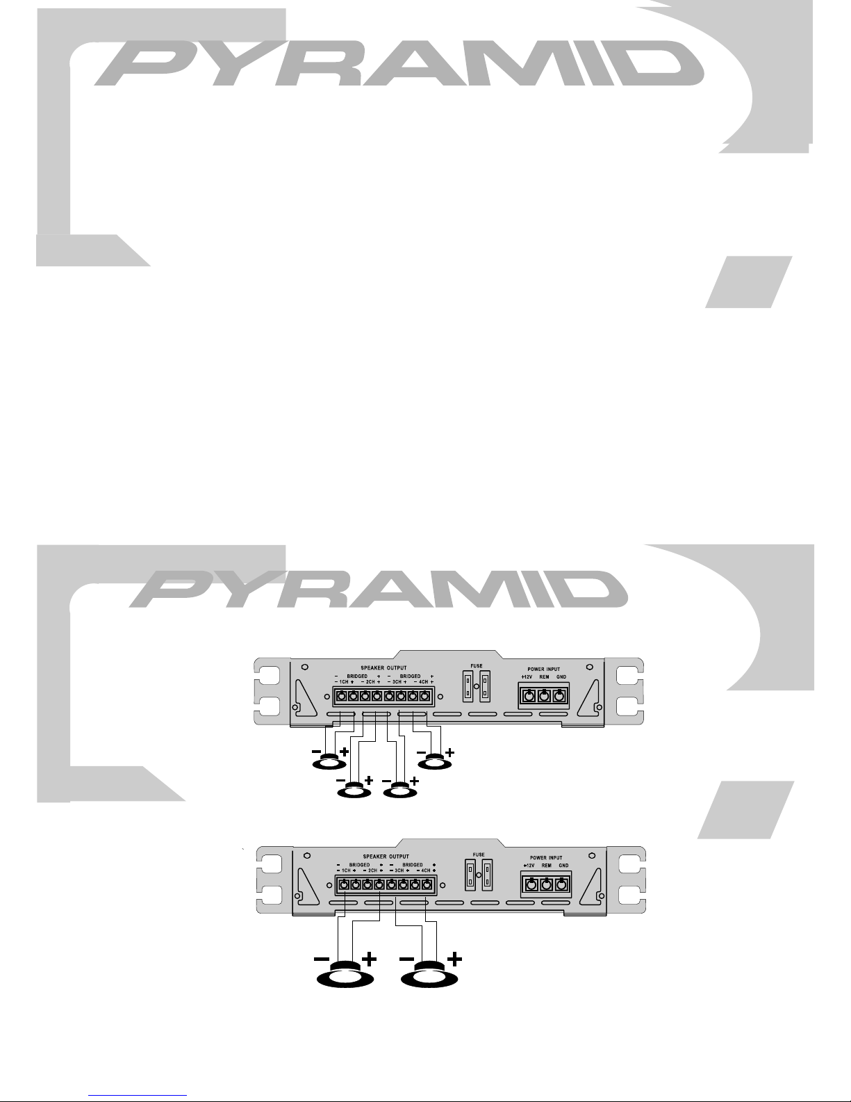
4ch Output Mode
L
FRONT speaker
R
Bridged Dual Mono Output Mode
L
speaker connections
4ch amp PB844
R
REAR speaker
L
MINIMUN
SPEAKER
IMPEDANCE
speaker
R
4OHMS!
17
Page 8
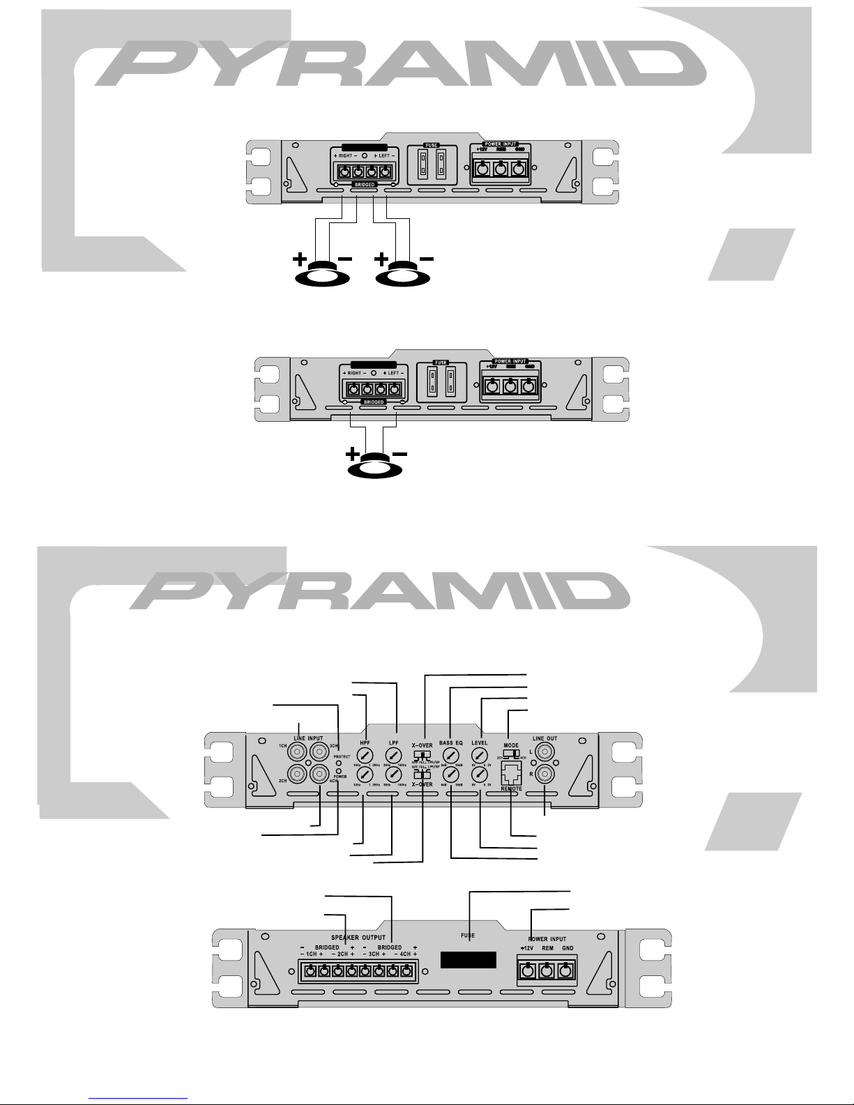
Stereo Output Mode
speaker connections
2ch amp PB744
SPEAKER OUTPUT
PB744
RIGHT speaker
LEFT speaker
Bridged Mono Output Mode
SPEAKER OUTPUT
speaker speaker
16
features and controlsfeatures and controls
4ch amp PB1644
PB1617X
PB1644
CH1/2 low pass frequency control
CH1/2 high pass frequency control
protection LED
CH1/2 input level control
CH3/4 input level control
power LED
CH3/4 high pass frequency control
CH3/4 low pass frequency control
CH3/4 crossover mode selector control
CH3/4 speaker connections
CH 1/2speaker connections
CH1/2 crossover mode selector switch
CH1/2 bass boost level control
CH1/2 level inputs
2/3/4 channel selectorl switch
output level
remote bass boost
CH3/4 level inputs
CH3/4 bass boost level control
power fuse
power terminals
7
Page 9
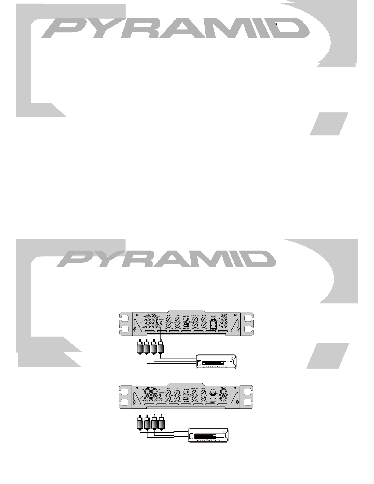
crossover mode selector
crossover mode selector
low pass frequency control
low pass frequency control
high pass frequency control
high pass frequency control
PB844
PB1644
bass boost level control
bass boost level control
input level control
input level control
low level inputs
low level inputs
high level inputs
high level inputs
power LED
power LED
protection LED
protection LED
power fuse
power fuse
power terminals
power terminals
speaker connections
speaker connections
features and specifications
features and specifications
4ch amp PB1644
when used with normal, full range systems, set this switch to “FULL”. If
when used with normal, full range systems, set this switch to “FULL”. If
you wish the internal crossover to power a driver of specific frequency
you wish the internal crossover to power a driver of specific frequency
range , use the “LOWPASS” or “HIGHPASS” settings.
range , use the “LOWPASS” or “HIGHPASS” settings.
when the crossover selector switch is in “low pass” mode, this control
when the crossover selector switch is in “low pass” mode, this control
sets the upper frequency limit for audio program sent to the speakers.
sets the upper frequency limit for audio program sent to the speakers.
when the crossover selector switch is in “high pass” mode, this control
when the crossover selector switch is in “high pass” mode, this control
sets the upper frequency limit for audio program sent to the
sets the upper frequency limit for audio program sent to the
use this control to match the outputs of you head unit to the amplifier.
use this control to match the outputs of you head unit to the amplifier.
Starting with
Starting with
the amp level control until distortion begins to occur, and reduce slightly
the amp level control until distortion begins to occur, and reduce slightly
from this point.
from this point.
this amp features gold-plate RCA input jacks for high impedance input.
this amp features gold-plate RCA input jacks for high impedance input.
Use these with car stereo output which uses RCA-type connector cables.
Use these with car stereo output which uses RCA-type connector cables.
if your car stereo lacks RCA-type output jacks, you may connect speaker
if your car stereo lacks RCA-type output jacks, you may connect speaker
output
output
this control permits adjustment of the bass level up to an increase of
this control permits adjustment of the bass level up to an increase of
approximately 18 dB.
approximately 18 dB.
this indicator is illuminated when power is applied.
this indicator is illuminated when power is applied.
this indicator is illuminated when built-in protection circuitry is activated.
this indicator is illuminated when built-in protection circuitry is activated.
the fuse protects the amplifier and your car’s electrical system from short
the fuse protects the amplifier and your car’s electrical system from short
circuit conditions.
circuit conditions.
use these connectors to deliver power, ground and remote turn-on control
use these connectors to deliver power, ground and remote turn-on control
to the amplifier.
to the amplifier.
these terminals
these terminals
minimum signal loss.
minimum signal loss.
your head unit set at about the 2 o’clock position, increase
your head unit set at about the 2 o’clock position, increase
leads to these input connectors.
leads to these input connectors.
are 14K gold plated to guarantee high conductivity and
are 14K gold plated to guarantee high conductivity and
speakers.
speakers.
R
output [email protected] DC, 1KHz
RMS Power @ 4 ohms
RMS Power @ 2 ohms
Maximum Power Output
frequency response
input impedance
low level inputs
high level inputs
input sensitivity
low level inputs
power supply voltage
power supply voltage
matching speaker
maximum current draw
maximum current draw
dimensions(W×H×L)
dimensions(W×H×L)
impedance
stereo mode
bridged mode
mm
mm
inches
inches
100Watts×4
200Watts×2
500Watts×4
10Hz-70KHz
10K Ohms
100 Ohms
200mV
14.4V DC Neg.Ground (10.5-16V)
2-4 Ohms
4-8 Ohms
80A
222×48×450
8.88×1. 92×18.1
8
6
PB317X
PB844
PB717X
PB1644
4ch amp PB844 PB1644
4ch mono input connections using low level inputs
LEFT FRONT Audio Outputs
LEFT REAR Audio Outputs
2ch mono minput connections using low level inputs
RIGHT REAR Audio Outputs
RIGHT FRONT Audio Outputs
L
Y adaptors
R
mono connections
head unit
96.8
head unit
96.8
15
16
Page 10
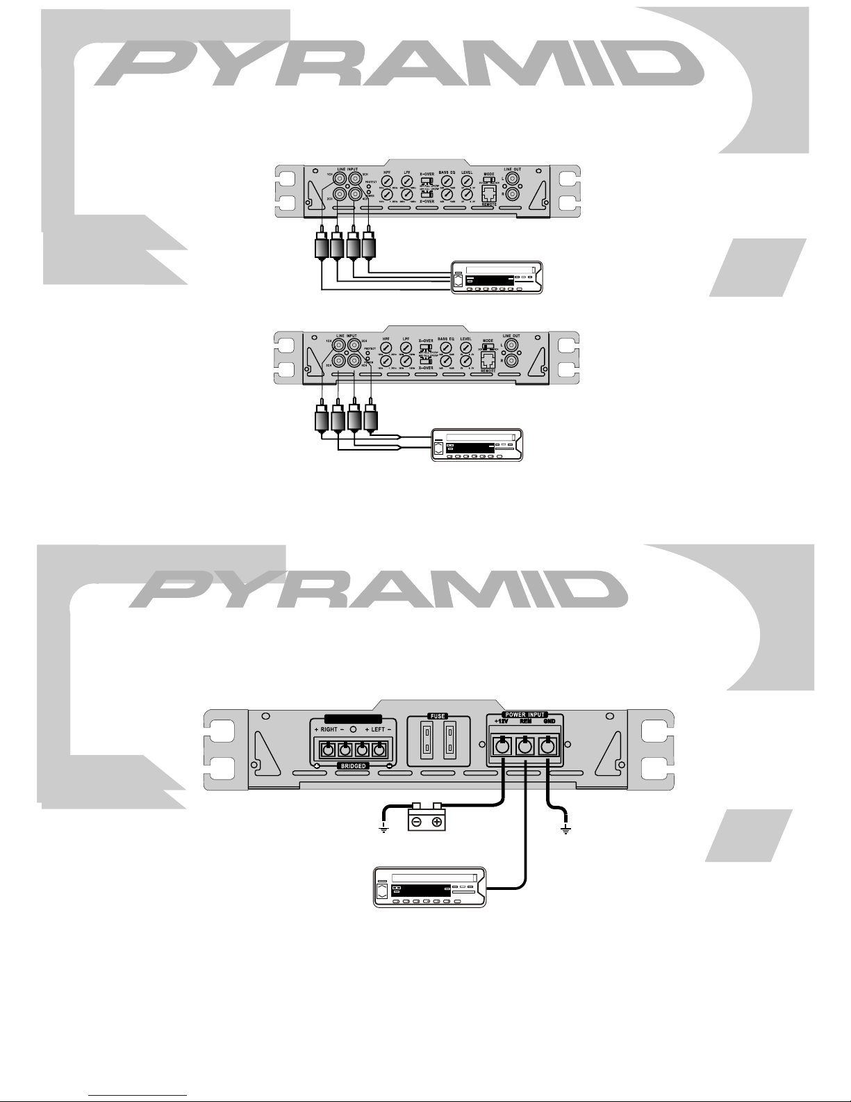
PB417X
PB844
PB617X
PB1644
2/4 channel input connections
4ch amp PB844 PB1644
4ch input connections using low level inputs
L/R FRONT
Audio Outputs
2ch input connections using low level inputs
L/R REAR
Audio Outputs
Y adaptors
head unit
96.8
head unit
L
R
96.8
14
17
PB417X
PB744
SPEAKER OUTPUT
electrical connections
2ch amp PB744
+12V battery
head unit
96.8
to remote turn-on +12V
9
8
Page 11
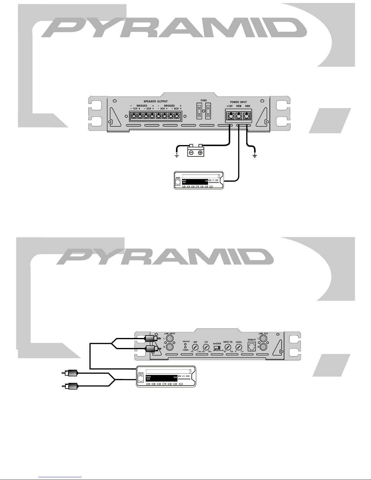
electrical connections
4ch amp PB844
PB844
10
+12V battery
head unit
96.8
to remote turn-on +12V
mono input connections
2ch amp PB744
using low level inputs
PB744
To a sencond amplifier
Y Adaptors
96.8
head unit
13
PLEASE NOTE! If using high level inputs,
do not use the low level RCA inputs at the
same time!
Page 12
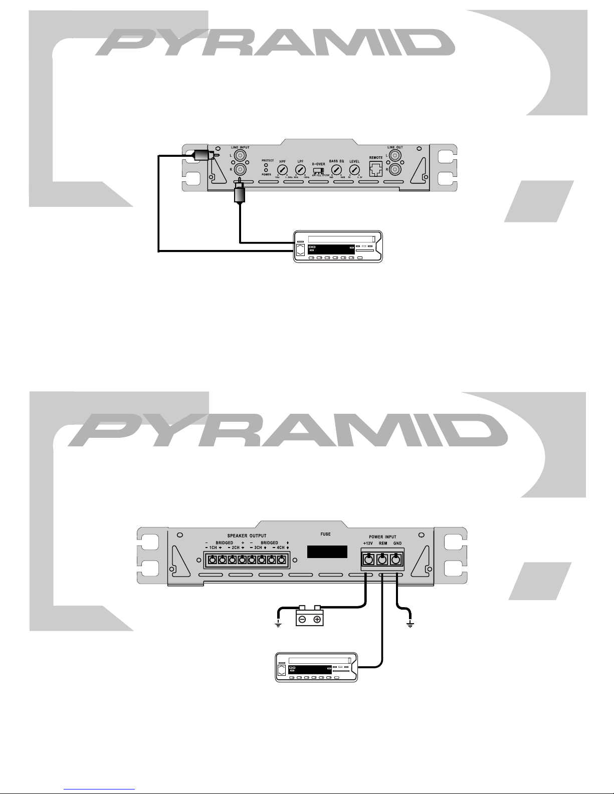
PB744
L/R Audio
Outputs
stereo input connections
2ch amp PB744
12
head unit
96.8
PLEASE NOTE! If using high level inputs,
do not use the low level RCA inputs at the
same time!
PB1644
+12V battery
head unit
electrical connections
4ch amp PB1644
96.8
to remote turn-on +12V
11
 Loading...