

HIGH PERFORMANCE CAR AUDIO
MODEL:CR-82
8 CHANNEL
ELECTRONIC CROSSOVER
NETWORK SYSTEM
– 1 –
www.pyramidcaraudio.com

INTRODUCTION
This CR-82 is an Electronic Crossover Network with which you can install
various types of multi-channel amplifier systems in a car.
This CR-82 is 8-channel crossover system
(Subwoofer, Mid-range, High-pass and Flat).
Before designing and installing your system.
Please read this manual carefully so that you can set up the system that
practically suits you.
Getting the CR-82 in the center of your multi-amplifier car stereo system.
Your car stereo system will provide you with the ultimate sound reproduction.
FEATURES & SPECIFICATIONS
✻ 2-Way stereo input ... Subwoofer/Front
4-Way stereo output ... Subwoofer/Mid-range/High Pass/Flat
✻ DC to DC converter power supply.
✻ Individual output level controls for each stereo channel.
✻ Variable subwoofer boost 0- 10dB at 40Hz.
✻ Subwoofer channel 45/80/150/200Hz.
✻ Subwoofer phase shift 0-180 degree.
✻ Subwoofer STEREO/MONO switch.
✻ Subwoofer input ON/OFF switch.
✻ Selectable band pass channel 100/150/200/Flat to 2.5k/3.5k/5k/7k
✻ Signal to Noise ratio :>90dB.
✻ Distortion : less than 0.02%
✻ Power supply :12-16V DC, Neg. Gnd.
– 2 –
FUNCTIONS
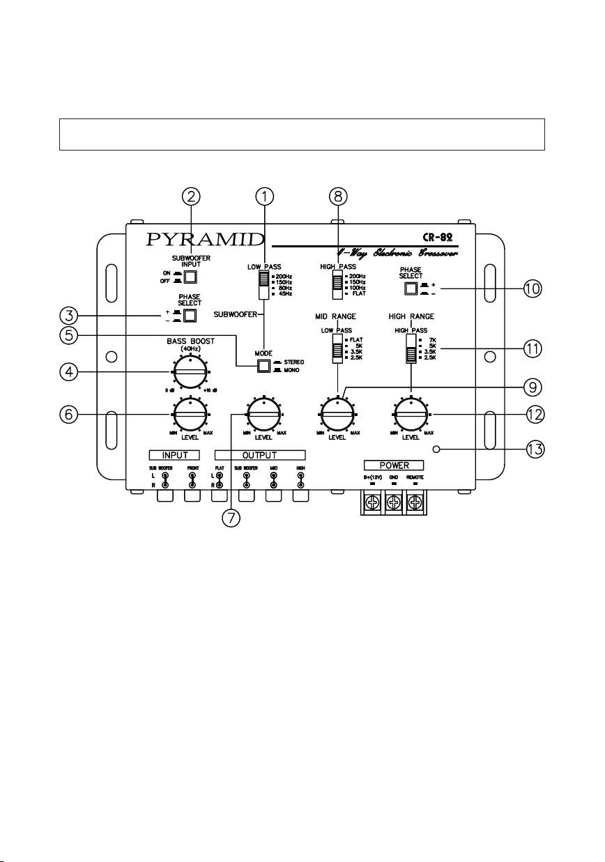
1 CROSSOVER POINT SELECTOR (SUBWOOFER)
Controls the subwoofer output frequency at 45,80,150,200Hz
2 SUBWOOFER INPUT SWITCH
When your car radio has subwoofer output to connect the unit's subwoofer
input;Push the switch to the "OFF" Position.
If your car radio only has line output to connect the unit 's line input; Push
the switch to the "ON" Position
– 3 –

3 PHASE SHIFTER SELECTOR (SUBWOOFER)
Allows you to change the phase of your subwoofer from 0 to 180 degrees
to help compensate for timing differences between drivers.
4 BASS BOOST CONTROL (40Hz)
Frequencies around 40Hz can be boosted at the maximum of +10dB.
5 STEREO/MONO SELECTOR (SUBWOOFER)
Set the selector to MONO to make subwoofer output monaural.
6 FLAT CHANNEL GAIN CONTROL
By turning this control clockwise you increase flat channel level.
7 SUBWOOFER GAIN CONTROL
By turning this control clockwise you increase subwoofer channel level.
8 MIDDLE RANGE CROSSOVER POINT SELECTOR
The high Pass frequency(100,150,200Hz,Flat) should match the low crossover point, the low frequency(2.5k,3.5k,5k,Flat)should match the high
crossover point.
9 MIDDLE RANGE GAIN CONTROL
By turning this control clockwise you increase middle range channel level.
0 PHASE SHIFTER SELECTOR(HIGH PASS)
Allows you to change the phase of your high pass from 0 to 180 degrees
to help compensate for timing differences between drivers.
q HIGH PASS CROSSOVER POINT SELECTOR
Control the high pass output at 2.5k,3.5k,5k,7k.
w HIGH PASS GAIN CONTROL
By turning this control clockwise you increase high pass channel
e POWER ON INDICATOR
The LED light up when the units is powered on.
– 4 –

FUNCTIONS
r SUBWOOFER INPUT CONNECTORS
t FRONT INPUT CONNECTORS
y FLAT OUTPUT CONNECTORS
u SUBWOOFER OUTPUT CONNECTORS
i MIDDLE RANGE OUTPUT CONNECTORS
o HIGH PASS OUTPUT CONNECTORS
ELECTRONIC CONNECTIONS & WIRING
✻ Power connection
• B+(l2V):Connect a red wire(at least l0-12 gauge)to the car battery or
other power source.
• REMOTE :Connect an orange wire to remote activating(l2V DC)wire of car
stereo or equalizer.
• GND :Connect a black wire(at least l0-12 gauge)to the car chassis for
ground connection.
– 5 –

ELECTRONIC CONNECTIONS & WIRING
✻ Signal connection
– 6 –

TROUBLE SHOOTING SECTION
1. SIGNAL PROCESSOR DOES NOT TURN ON:
✻ Check all fuses.
✻ Check all power(positive ,remote) wire connections.
✻ Check that ground wire is properly connected.
2. LED POWER ON INDICATOR NOT GOING ON:
✻ Same as sign l remedy.
3. SOUND DISTORTION AT LOW VOLUME LEVEL:
✻ Output level not set correctly.
4. LEVEL OF SOUND IS LOW:
✻ Check input gain control ,match to deck output.
✻ Check the RCA patch cords for loose or misconnected cables.
5. A WHINING SOUND CAN BE HEARD THROUGH THE SPEAKERS
AT LOW VOLUME LEVEL WITH RUNNING ENGINE:
✻ Check the power wire(red)with good connection directly to the battery
and ground point must make good contact with chassis ground.
INSTALLATION
– 7 –

MEMO
– 8 –
 Loading...