

Page 1
OWNER’S MANUAL
MANUALLY TUNED SYNTHESIZER STEREO RADIO
WITH COMPACT DISC PLAYER DIGITAL
Page 2

CONTENTS
Installation .....................................................................................................3
Remove The Unit From The Dash Board....................................................4
Operation .......................................................................................................5
Radio Operation ............................................................................................6
CD Operation.................................................................................................7
Wiring Connection ........................................................................................8
Specification..................................................................................................8
2
Page 3
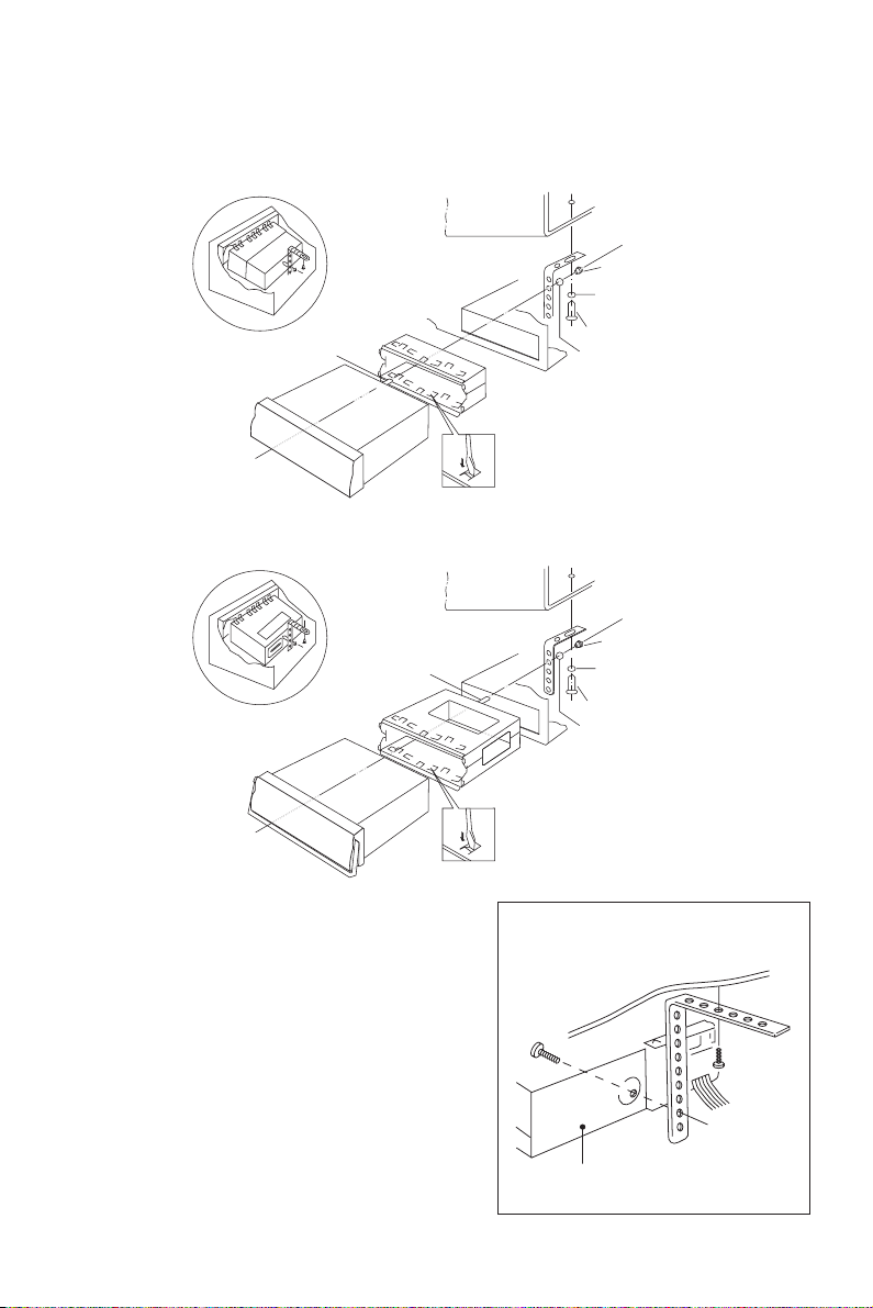
INSTALLATION
Here is the installation diagram.
NON PULL-OUT UNIT
DASH BOARD
PULL-OUT UNIT
HEX BOLT
METAL MOUNTING STRAP
MOUNTING HOUSING
DASH BOARD
METAL MOUNTING STRAP
HEX BOLT
SLIDE BRACKET HOUSING
CONSOLE
CONSOLE
HEX NUT
SPRING
WASHER
TAPPING
SCREW
PLAIN WASHER
HEX NUT
SPRING
WASHER
TAPPING
SCREW
PLAIN WASHER
Precautions
1. Choose the mounting location where the
unit will not interfere with the normal
driving functions of the driver.
2. Avoid installing the unit where it would
be subject to high temperature, such as
from direct sunlight, or from hot air, from
the heater, or where it would be subject
to dust, dirt or excessive vibration.
3. For safe installation, use the mounting
hardware provided by the manufacturer.
Fire Wall
Bracket
3
Page 4

REMOVE THE UNIT FROM THE DASH BOARD
FOR NON-PULL OUT VERSION
1. Remove the metal strap attached to the back of the unit.
2. Disconnect all the wires of the unit and the antenna plug.
3. Remove the handle frame from the trim plate.
4. Insert the supplied key into the slot as shown, and slide the unit out of the dash
board while holding the trim plate.
5. Remove the key from the slot.
SLOT
SLEEVE
RELEASE KEY
TRIM
PLATE
HANDLE FRAME
FOR PULL-OUT VERSION
1. Remove the metal strap attached to the back of the unit.
2. Disconnect all the wires of the unit and the antenna plug.
3. Lift up the handle and pull the trim plate out.
HANDLE
TRIM PLATE
4
SLEEVE
Page 5

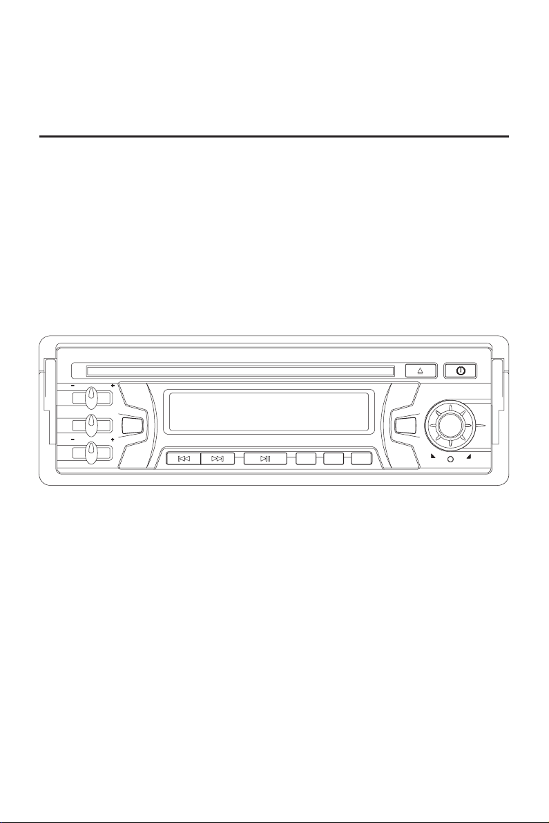
OPERATION
3 7 12 1
2
4 5
15
14 11 6 9 10 17 818
1613
GENERAL OPERATION
ON/OFF
Press PWR button (1) to turn on the unit. Press it again to turn it off.
BALANCE
Slide the button (2) left or right to adjust sound balance between left and right speakers.
VOLUME
Slide the button (3) to left or right to adjust volume level.
TONE CONTROL
Slide the button (4) left or right to obtain the desired sound quality.
SELECT MODE
Press MOD button (5) to change radio or CD mode.
LIQUID CRYSTAL DISPLAY
The LCD (16) can show the current state of the unit.
RESET BUTTON FUNCTION
RESET button (17) is placed on the housing and must be activated with either a
ballpoint pen or thin metal object. The RESET button (17) is to be activated for the
following reasons:
- Initial installation of the unit when all wiring is completed.
- All the function buttons do not operate.
- Error symbol on the display.
PULL-OUT HANDLE (FOR PULL-OUT VERSION ONLY)
In case of taking away the car radio unit from the car., lift up the handle (18) and pull it out
5
Page 6

RADIO OPERATION
BAND
Press BND button (7) to change bands as below:
FM AM
SELECT STATION
Rotate the TUNING knob (8) clockwise or anti-clockwise to adjust the frequency
upward or downward.
LOCAL/DISTANT
Press the LOC/RPT button (9) to select between local setting for reception of strong
station and distant setting for reception of weak stations when tuning.
MONO/STEREO
In FM band, press MON/INT button (10) to select mono or stereo reception for radio
stations. You can sometimes improve reception of distant stations by selecting mono
operation.
6
Page 7

CD OPERATION
DISC PLAY
Gently insert a compact disc with the label side facing up into the disc slot (13). The
disc is then automatically loaded into the unit and starts playing with the first track of
the disc. The digital display will indicate the track number and the time of the track.
EJECT
Press
(eject) button (12) to stop CD play and eject CD from the slot. Receiver switches
to radio operation.
PAUSE CD
During CD playing, press
Press it again to resume playback.
SKIP TRACKS
Press TRACK button (15) or TRACK button (14) to choose the following track
or the previous track. Track numbers show on the display.
FAST FORWARD AND FAST REVERSE
Hold TRACK button (15) or TRACK button (14) for several seconds to fast
forward or fast reverse. Releasing the button to stop fast playing.
REPEAT
During CD operation, press LOC/RPT button (9) to continuously repeat playing the
current track. Press it again to release the mode.
INTRO: PREVIEW ALL TRACKS
During CD operation, press MON/INT button (10) to play first several seconds of each
track. Press it again to stop intro and listen to track.
button (11) to temporarily stop playing.
RANDOM: PLAY ALL TRACKS IN THE RANDOM ORDER
During CD operation, press and hold RND button (6) for several seconds to play all
tracks in the random order. Press it again to cancel the function.
7
Page 8

WIRING CONNECTION
ANTENNA CONNECTOR
(FOR POWER ANT. VERSION ONLY)
POWER
ANTENNA
IGNITION
B(+)
RED
YELLOW
FUSE
MAIN UNIT
(FOR RCA LINE OUT VERSION ONLY)
RCA CABLE
Rch RED
Lch WHITE
LEFT
SPEAKER
GREEN
BLACK
GROUND/SPK.COMMON
GREY
RIGHT
SPEAKER
Note:
After ACC turn off, turn on the unit again, it will return to FM mode.
SPECIFICATION
General
Power Supply Requirements
Chassis Dimensions
-----------------------------------------
Maximum Output Power
--------------------------------
------------------------------------
CD Player
Signal to Noise Ratio
Channel Separation
Frequency Response
----------------------------------------------------
-----------------------------------------------------
------------------------------------------------------
Radio Section
FM BAND 2 BAND (Europe) 2 BAND (U.S.A.)
Frequency Range 88 MHz – 108 MHz 88 MHz – 108 MHz
Intermediate Frequency 10.7 MHz 10.7 MHz
Usable Sensitivity (Mono) Better than 25 dBu Better than 25 dBu
Stereo Separation at 1 KHz More than 24 dB More than 24 dB
MW BAND
Frequency Range 520 KHz – 1620 KHz 530 KHz – 1710 KHz
Intermediate Frequency 455 KHz 455 KHz
Usable Sensitivity (S/N 20 dB) Better than 42 dBu Better than 42 dBu
DC 12 Volts, Negative Ground
178 (W) x 163 (D) x 51 (H) mm
7 W x 2
More than 60 dBu
More than 60 dBu
100 Hz - 15 KHz
8
88-C1970-00
 Loading...