


Rechargeable Li-ion Battery
US2000C Operation Manual
Information Version: 20CPSV1102
PM0MUS3C0009


This manual introduces US2000C from Pylontech. Please read this manual
before you to install the battery and follow the instruction carefully during the
installation process. Any confusion, please contact Pylontech immediately for
advice and clarification.
1. Symbol in label, manual and product 1
2. Safety Precautions 2
2.1 Before Connecting 3
2.2 In Using 3
3. Introduction 4
3.1 Features 4
3.2 Specification 6
3.3 Equipment interface instruction 8
Definition of RJ45 Port Pin 10
4. Safe handling of lithium batteries guide 12
4.1 Schematic diagram of solution 12
4.2 Danger label 12
4.3 Tools 13
4.4 Safety gear 13
5. Installation and operation 14
5.1 Package items 14
5.2 Installation location 16
5.3 Grounding 17
5.4 Put into cabinet or racks 18
5.5 Put into bracket 20
5.6 Suitable breaker 23
5.7 Power on 23
5.8 Power off 25
5.9 Multi-group mode 26
6. Trouble shooting 28
7. Emergency Situations 32
8. Remarks 33

1
1. Symbol in label, manual and product
Caution! Warning! Reminding.
Safety related information.
Risk of battery system failure or life cycle reduces.
Do not reverse connection the positive and negative.
Do not place near open flame
Do not place at the children and pet touchable area.
Warning electric shock.
Warning Fire.
Do not place near flammable material
Read the product and operation manual before operating the
battery system!
Grounding.
Recycle label.

2
The certificate label for EMC.
Label for Waste Electrical and Electronic Equipment (WEEE)
Directive (2012/19/EU)
The certificate label for Safety by TÜV Rheinland.
2. Safety Precautions
Reminding
1) It is important and necessary to read the user manual carefully (in the
accessories) before installing or using battery. Failure to do so or to follow
any of the instructions or warnings in this document can result in electrical
shock, serious injury, or death, or can damage battery, potentially rendering
it inoperable
2) If the battery is stored for long time, it is required to charge them every six
months, and the SOC should be no less than 90%
3) Battery needs to be recharged within 12 hours, after fully discharged
4) Do not install the product in outdoor environment, or an environment out of
the operation temperature or humidity range listed in manual.
5) Do not expose cable outside
6) Do not connect power terminal reversely.
7) All the battery terminals must be disconnected for maintenance
8) Please contact the supplier within 24 hours if there is something abnormal.
9) Do not use cleaning solvents to clean battery
10) Do not expose battery to flammable or harsh chemicals or vapors
11) Do not paint any part of battery, include any internal or external components

3
12) Do not connect battery with PV solar wiring directly
13) The warranty claims are excluded for direct or indirect damage due to items
above.
14) Any foreign object is prohibited to insert into any part of battery
Warning
2.1 Before Connecting
1) After unpacking, please check product and packing list first, if product is
damaged or lack of parts, please contact with the local retailer
2) Before installation, be sure to cut off the grid power and make sure the
battery is in the turned-off mode
3) Wiring must be correct, do not mistake the positive and negative cables,
and ensure no short circuit with the external device
4) It is prohibited to connect the battery and AC power directly
5) The embedded BMS in the battery is designed for 48VDC, please DO NOT
connect battery in series
6) Battery must connect to ground and the resistance must be less than 0.1Ω
7) Please ensured the electrical parameters of battery system are compatible
to related equipment
8) Keep the battery away from water and fire.
2.2 In Using
1) If the battery system needs to be moved or repaired, the power must be
cut off and the battery is completely shutdown
2) It is prohibited to connect the battery with different type of battery.
3) It is prohibited to connect batteries with faulty or incompatible inverter
4) It is prohibited to disassemble the battery (QC tab removed or damaged);
5) In case of fire, only dry powder fire extinguisher can be used, liquid fire

4
extinguishers are prohibited
6) Please do not open, repair or disassemble the battery except staffs from
Pylontech or authorized by Pylontech. We do not undertake any consequences
or related responsibility which because of violation of safety operation or
violating of design, production and equipment safety standards.
3. Introduction
US2000C lithium iron phosphate battery is the new energy storage products
developed and produced by Pylontech, it can be used to support reliable power
for various types of equipment and systems.
US2000C has built-in BMS battery management system, which can manage
and monitor cells information including voltage, current and temperature.
3.1 Features
1) NEW: Build-in soft-start function able to reduce current strike when inverter
need to start from battery.
2) NEW: Dual active protection on BMS level.
3) NEW: Automatic address setting when connect in multi-group.
4) NEW: Support wake up by 5~12V signal from RJ45 port.
5) NEW: Support upgrade battery module from upper controller via CAN or
RS485 communication.
6) NEW: Enable 95% depth of discharge, available for the inverter which
completely follow Pylontech latest protocol to operate.
7) The module is non-toxic, non-polluting and environmentally friendly
8) Cathode material is made from LiFePO4 with safety performance and long
cycle life
9) Battery management system (BMS)has protection functions including over-
discharge, over-charge, over-current and high/low temperature
10) The system can automatically manage charge and discharge state and

5
balance voltage of each cell
11) Flexible configuration, multiple battery modules can be in parallel for
expanding capacity and power
12) Adopted self-cooling mode rapidly reduced system entire noise
13) The module has less self-discharge, up to 6 months without charging it on
shelf, no memory effect, excellent performance of shallow charge and
discharge
14) Small size and light weight, standard of 19-inch embedded designed
module is comfortable for installation and maintenance
15) Compatible with the US3000, and US2000.
*Mixture using master battery priority:
US3000C>US2000C>US3000>US2000
For same type of module always use the latest production unit as master.
*Mixture using battery deployment option:
Master battery (1
st
)
US3000C/US2000C
Slave 2nd ~8
th
US3000C/US2000C/US3000/US2000
Slave 9th ~16
th
US3000C/US2000C

6
3.2 Specification

7
Basic Parameters
US2000C
Nominal Voltage (V)
48
Nominal Capacity (Wh)
2400
Usable Capacity (Wh)
2280
Dimension (mm)
440*410*89
Weight (Kg)
22.5
Discharge Voltage (V)
44.5 ~ 53.5
Charge Voltage (V)
52.5 ~ 53.5
Recommend Charge/Discharge Current (A)
25
Max. Charge/Discharge Current (A)
50-89@60sec
Peak Charge/Discharge Current (A)
90~200@15sec
Communication
RS485, CAN
Depth of discharge (%)
95
Configuration (max. in 1 battery group)
16pcs
Working Temperature
0℃~50℃ Charge
-10℃~50℃ Discharge
Shelf Temperature
-20℃~60℃
Short current/duration time
<4000A/2ms
Protective class
I
IP rating of enclosure
IP20
Humidity
5 ~ 95%(RH) No Condensation
Altitude(m)
<4000
Certification
TÜV / CE / UN38.3
Design life
15+ Years (25℃/77℉)
Cycle Life
>6,000 25℃
Reference to standards
IEC62619, IEC63056 UL1642,
IEC61000-6-2, IEC61000-6-3,
UN38.3

8
3.3 Equipment interface instruction
Power Switch
ON: ready to turn on.
OFF: power off. For storage or shipping.
Start
Turn on: press more than 0.5s to start the battery module
Turn off: press more than 0.5s to turn off the battery.
RUN
Green LED lighting to show the battery running status
Alarm
Red LED flashing to show the battery has alarm; lighting to show the battery is
under protection.
SOC
6 green LEDs to show the battery’s current capacity.
ADD Switch
Dip1: RS485 baud rate: 1: 9600; 0: 115200. After change, please restart battery.
Dip2: CAN terminal resistance on BMS side. 1: NONE. 0: connected. After
change, no restart required. In single group mode, please keep dip2 at 0
position. For multi-groups, please refer to [5.8].
Dip3~4, reversed.

9
Based on design of BMS, the dip switch is deployed physically reversely. For
instance:
Dip1
Dip2
Dip3
Dip4
The corresponding
position of switch
Status
0 0 0
0
RS485:115200
CAN terminal
resistance: connected
1 0 0
0
RS485:9600
CAN terminal resistance:
connected
0 1 0
0
RS485: 115200
CAN terminal resistance:
NONE
Console
For manufacturer or professional engineer to debug or service.
Pin3
232-TX
Pin4*
+5~+12V for wake up
Pin5*
GND for wake up
Pin6
232-RX
Pin8
232-GND
*Wake up signal shall ≥0.5Sec, current between 5~15mA. After send wake up signal, the voltage shall
disappear for normal operation.
Contact
Pin1
Input, passive signal. On: turn off battery. Off: normal.
Pin2
Pin3
Output1. On: stop charge.
+
Pin4
-
Pin5
Output2. On: stop discharge.
+
Pin6
-
Pin7
Output3. On: BMS error.
+
Pin8
-

10
Output request signal voltage ≤25V
CAN
500 Kbps. 120Ω. For connection to LV-HUB, inverter, or upper battery.
RS485
9600 or 115200 bps.120Ω. For connection to inverter, or slave battery.
Link Port 0, 1
for communication between multiple parallel batteries.
Definition of RJ45 Port Pin
A/CAN
B/RS485
Pin1
These pins shall be NULL.
If not, may influence communication
between BMS and inverter.
Pin2
Pin3
Pin4
CAN-H
CAN-H (single group)
Pin5
CAH-L
CAN-L (single group)
Pin6
CAN-GND
CAN-GND (single group)
Pin7
485A
485A
Pin8
485B
485B
Power Terminals
Power cable terminals: there are two pair of terminals
with same function, one connects to equipment, the
other one paralleling to other battery module for capacity
expanding.
For power cables uses water-proofed connectors. must
keep pressing this Lock Button while pulling out the
power plug.
11
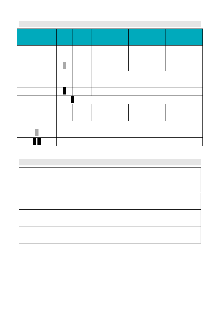
LED Status Indicators
Condition
RU
N
ALR 1 2
3
4 5 6
Power off
- - - - - - - - Power on
● ● ● ● ● ● ● ● Idle/Normal
● - - - - - -
-
Charge
●
-
Show soc; highest LED flash
on: 0.5s; off 0.5s
Discharge
●
Show soc
Alarm
ALR:●; Other LEDs are same as above.
System
error/Protect
- ● - - -
- -
●/●
ON ● flash, on: 0.3s; off: 3.7s
●/●
flash, on:0.5s; off: 1.5s
BMS basic function
Protection and alarm
Management and monitor
Charge/Discharge End
Cells Balance
Charge Over Voltage
Intelligent Charge Model
Discharge Under Voltage
Charge/Discharge Current Limit
Charge/Discharge Over Current
Capacity Retention Calculate
High/Low Temperature(cell/BMS)
Administrator Monitor
Short Circuit
Operation Record
Power Cable Reverse
Soft start of inverter

12
4. Safe handling of lithium batteries guide
4.1 Schematic diagram of solution
4.2 Danger label

13
4.3 Tools
Wire cutter
Crimping modular plier
Screwdriver
NOTE
Use properly insulated tools to prevent accidental electric shock or short circuits.
If insulated tools are not available, cover the entire exposed metal surfaces of
the available tools, except their tips, with electrical tape.
4.4 Safety gear
It is recommended to wear the following safety gear when dealing with the
battery pack
Insulated gloves
Safety goggles
Safety shoes

14
5. Installation and operation
5.1 Package items
Unpacking and check the Packing List
1) For battery module package:
- Battery module
- Two 4AWG power cables and one RJ45 communication cable
- 10AWG grounding cable
1000

15
2) For External cable kits:
NOTE
Power and communication cables to connect to inverter belongs to an External
Cable Kit, NOT include in battery carton box. They are in another extra
small cable box. If there is anything missed please contact dealer.
Two 4AWG power cables (peak current capacity 120A, constant 100A) and
RJ45 communication cable for each energy storage system:
For the external cables, the length shall less than 3 meters.
SN of RJ45cable
Mark
Pin
WI0SCAN30RJ1
With blue mark:
Battery-Inverter
Pin1~3: NULL
Pin4~8: pin to pin
For connection
to inverter
WI0SCAN35RJ3
With silver mark:
Battery-Battery
Pin1~8: pin to pin
For parallel
connection
between master
batteries
3000

16
5.2 Installation location
Make sure that the installation location meets the following conditions:
1) The area is completely waterproof
2) The floor is flat and level.
3) There are no flammable or explosive materials.
4) The ambient temperature is within the range from 0°C to 50°C.
5) The temperature and humidity is maintained at a constant level.
6) There is minimal dust and dirt in the area.
7) The distance from heat source is more than 2 meters.
8) The distance from air outlet of inverter is more than 0.5 meters.
9) The installation areas shall avoid of direct sunlight.
10) There is no mandatory ventilation requirements for battery module, but
please avoid of installation in confined area. The aeration shall avoid of
high salinity, humidity or temperature.
Caution
If the ambient temperature is out of the operating range, the battery stops
operating to protect itself. The optimal temperature range for the battery pack
to operate is 10°C to 40°C. Frequent exposure to harsh temperatures may
deteriorate the performance and life of the battery.

17
5.3 Grounding
Grounding cables shall be 10AWG or higher yellow-green cables. After
connection, the resistance from battery grounding point to Ground connection
point of room or installed place shall smaller than 0.1Ω.
1) based on metal directly touch between the module’s
surface and rack’s surface. If using painted rack the
corresponding place shall remove the painting.
2) install a grounding cable to the grounding point of the
modules.

18
5.4 Put into cabinet or racks
Put battery modules into cabinet and connect the cables:
1) Put the battery into the cabinet
2) Drive the 4 pcs screws
3) Connect the cables between battery modules
4) Connect the cables to inverter

19

20
5.5 Put into bracket
1) Dismantle the 2 holders of battery.
2) Put the battery into 2 pcs of bracket.

21
3) Use 4 location holes, stack the batteries together. And connect the 4 locker
together.
4) Maximum 4 in stack.

22
NOTE
After installation, do not forget to register online for full warranty:
http://www.pylontech.com.cn/service/support
Caution
1) follow local electric safety and installation policy, a suitable breaker between
battery system and inverter could be required.
2) all the installation and operation must follow local electric standard.

23
5.6 Suitable breaker
1) The rated voltage shall ≥60V DC. Do NOT use AC breaker.
2) The type of breaker shall be type C (recommended) or type D.
3) The rated current shall match with system design:
shall consider the DC current on inverter side.
the number of power cable: for instance, if only one pair of 4awg cable, the
rated current of breaker shall be 125A or smaller.
4) The Icu required:
the short circuit current for calculation of each module is 2500A. for instance:
Icu of breaker
1~4 modules
Must ≥10kA
5~8 modules
Must ≥20kA
5.7 Power on
Double check all the power cable and communication cable.
1) Switch on all the battery modules:
2) The one with empty Link Port 0 is the Master Battery Module, others are
slaves (1 master battery configure with maximum 15 slave batteries):
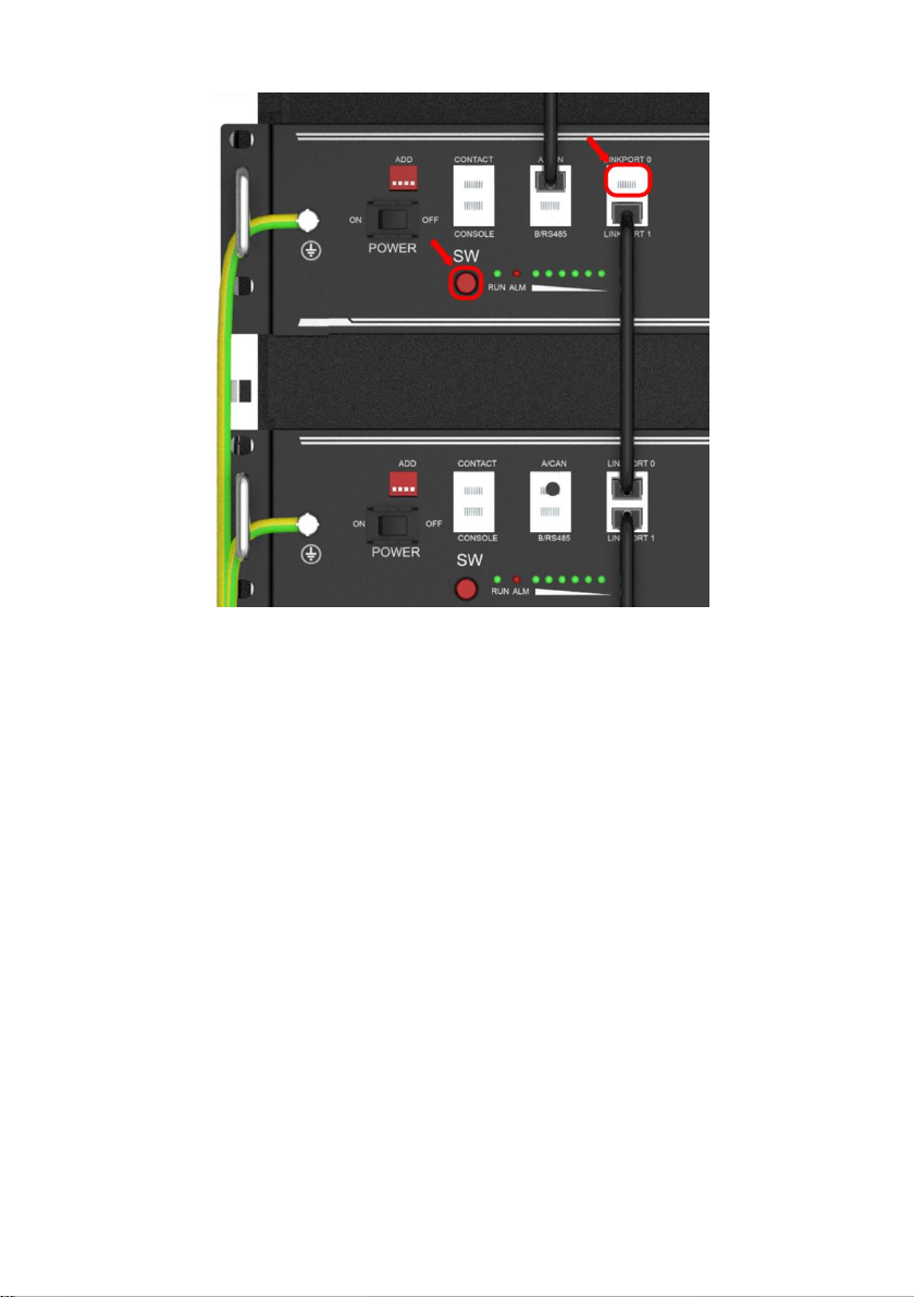
24
3) Press the red SW button of master battery to power on, all the battery
LED light will be on one by one from the Master battery:

25
Note:
1) After the battery module powered on, the soft-start function takes 3sec to
active. After soft-starts battery ready to output high power.
2) During capacity expansion or replacement, when parallel different
SOC/voltage of module together, please maintain the system in idle for
≥15mins or till the SOC LEDs becomes similar (≤1dot difference) before
normal operation.
5.8 Power off
1) Turn external power source off.
2) Press red SW switch of master battery. Then all batteries will off.
3) Switch Power switch OFF.

26
5.9 Multi-group mode
By RS485: DO NOT need LV-HUB.
Connect power cable first:
1) each pair of cable hold max 100A constant current. Connect enough pairs
of cable based on calculation of system current.
2) Suitable protection breaker between battery system and inverter is
required.
3) Make sure all dip switch of master batteries are R0XX, then turn ON
batteries.
R: is the baud rate of RS485 needed, all master batteries shall be the same.
4) After all batteries running and buzzer of master battery in group1 rings 3
times. Means all groups are online.
The interruption of each RS485 command shall at least≥1s.

27
By CAN:
Connect power cable first:
1) each pair of cable hold max 100A constant current. Connect enough pairs
of cable based on calculation of system current.
2) Suitable protection breaker between battery system and inverter is required.
3) connect power cable of LV-HUB
4) Make sure all dipswitch is X0XX, then turn ON batteries.
5) After all batteries running and buzzer of master battery in group1 rings 3
times. Means all groups are online.
6) Change the dip switch of master battery in group1 to X1XX. Then connect
communication cable between LV-HUB and master battery in group 1.
7) Then turn ON LV-HUB.
Detailed information please refer to manual of LV-HUB.

28
6. Trouble shooting.
- Communication related problem
Unable to communicate with inverter on compatible list.
Possible conditions:
1) RS485: baud rate. Check the dip switch1, set to correct one, and restart. All
master battery shall be the same.
2) CAN: terminal resistance. Check the dip switch2, set to 0 and retry.
3) CAN: pin. Try connect the CAN-H,L,GND only and do not connect other
pins to inverter.
- Functional related problem
1) Whether the battery can be turned on or not
2) If battery is turned on, check the red light is off, flashing or lighting
3) If the red light is off, check whether the battery can be charged/discharged
or not.
Possible conditions:
1) Battery cannot turn on, switch ON and press the red SW the lights are all
no lighting or flashing.
a) Capacity too low, or module over discharged.
solution: use a charge or inverter to provide 48-53.5V voltage. If battery can
start, then keep charge the module and use monitor tools to check the
battery log.
If battery terminal voltage is ≤45Vdc, please use ≤0.05C to slowly charge
the module to avoid affect to SOH.
If battery terminal voltage is >45Vdc, it can use ≤0.5C to charge.
If battery cannot start, turn off battery and repair.
2) The battery can turn on, but red light is lighting, and cannot charge or
discharge. If the red light is lighting, that means system is abnormal, please

29
check values as following
b) Temperature: Above 60℃ or under -10℃, the battery could not work.
Solution: to move battery to the normal operating temperature range
between 0℃ and 50℃
c) Current: If current exceeds 90A, battery protection will turn on.
Solution: Check whether current is too large or not, if it is, change the
settings on power supply side.
d) High Voltage: If charging voltage above 54V, battery protection will turn on.
Solution: Check whether voltage is too high or not, if it is, to change the
settings on power supply side. And discharge the module.
e) Low Voltage: When the battery discharges to 44.5V or less, battery
protection will turn on.
Solution: Charge the battery till the red light turns off.
f) Cell voltage high. The module voltage is lower than 54V, SOC LED does
not all on. When discharge the module protection disappear.
Solution: keep charge the module by 53-54V or keep the system cycle. The
BMS can balance the cell during cycling.
3) Unable to charge and discharge with red LED on. The temperature is 0~50
degree. Use charger to charge, not possible. Use load to discharge, not
possible.
g) Under permanent protection. The single cell voltage has been higher than
4.2 or lower than 1.5 or temperature higher than 80 degrees. Solution:
Switch off the module and contact your local distributor for repair.
4) Unable to charge and discharge without red LED on. The temperature is
0~50 degree. Use charger to charge, not possible. Use load to discharge,
not possible.
h) Fuse broken.
Solution: Switch off the module and contact your local distributor for repair.
5) Buzzer rings and all LED flash

30
i) High voltage protection.
Cell voltage higher than 4V or module voltage higher than 55.5V.
Solution: Battery system requires properly established communication
with inverter and correctly settings on inverter to run safely. Check the
setting of the inverter or charger, the charge voltage shall be 53.2~52.5Vdc;
Check the communication between battery system and inverter; Check the
ADD switch on battery module whether is set correctly or not;
Under this condition, the BMS remains functional without damage. Just
leave the module switched OFF and wait for the battery voltage drop down
naturally(15mins) then restart. If then no alarm comes out, this means the
module is ready for work
6) Buzzer rings and ALM solid red
j) Reverse connection of cables.
Solution: Power off all battery and inverters. Disconnect breaker. Check the
cable connection and disconnect all power cables. Check the power port
damaged or not. Then try turn on the single module, without any cable
connected. If no alarm, then it is reverse connection of cables. Switch off
the module and contact your local distributor.
k) MOSFAIL.
Solution: Power off all battery and inverters. Disconnect breaker. Check the
cable connection and disconnect all power cables. Check the power port
damaged or not. Check the setting of inverter or charger, check the
communication between inverter and battery system.
Try turn on the single module, without any cable connected. If still buzzer
rings. Then switch off the module and contact your local distributor.
7) After switch On, the module turns on directly
l) BMS failure.
Solution:Switch off the module and contact your local distributor.

31
Excluding the points above, if the faulty still cannot be located, turn off
battery and contact your local distributor.

32
7. Emergency Situations
1) Leaking Batteries
If the battery pack leaks electrolyte, avoid contact with the leaking liquid or
gas. If one is exposed to the leaked substance, immediately perform the
actions described below.
a) Inhalation: Evacuate the contaminated area and seek medical attention.
b) Contact with eyes: Rinse eyes with flowing water for 15 minutes and
seek medical attention.
c) Contact with skin: Wash the affected area thoroughly with soap and
water and seek medical attention.
Ingestion: Induce vomiting and seek medical attention.
2) Fire
NO WATER! Only dry powder fire or carbon dioxide extinguisher can be
used; if possible, move the battery pack to a safe area before it catches fire.
3) Wet Batteries
If the battery pack is wet or submerged in water, do not let people access it,
and then contact Pylontech or an authorized dealer for technical support.
Cut off all power switch on inverter side.
4) Damaged Batteries
Damaged batteries are dangerous and must be handled with the utmost
care. They are not fit for use and may pose a danger to people or property.
If the battery pack seems to be damaged, pack it in its original container,
and then return it to Pylontech or an authorized dealer.
Caution
Damaged batteries may leak electrolyte or produce flammable gas.

33
8. Remarks
Recycle and disposal
In case a battery (normal condition or damaged) needs disposal or needs
recycling, it shall follow the local recycling regulation (i.e. Regulation (EC) Nº
1013/2006 among European Union) to process, and using the best available
techniques to achieve a relevant recycling efficiency.
Storage, Maintenance and Expansion
1) It is required to charge the battery at least once every 6 months, for this
charge maintenance make sure the SOC is charged to higher than 90%
2) Every year after installation. The connection of power connector, grounding
point, power cable and screw are suggested to be checked. Make sure
there is no loose, no broken, no corrosion at connection point. Check the
installation environment such as dust, water, insect etc. make sure it is
suitable for IP20 battery system.
3) If the battery is stored for long time, it is required to charge them every six
months, and the SOC should be higher than 90%.
4) A new battery module can be add onto an existing system at any time.
Please make sure the new battery is acting as the master. The new module,
due to a higher SOH may have a difference on SOC with existing system,
but it will not affect the parallel connection system performance.
5)


Pylon Technologies Co., Ltd.
No. 73, Lane 887, ZuChongzhi Road, Zhangjiang Hi-Tech Park
Pudong, Shanghai 201203, China
T+86-21-51317699 | F +86-21-51317698
E service@pylontech.com.cn
W www.pylontech.com.cn
 Loading...