


Lithium-Ion Phosphate Energy Storage System
Force-H1-V2 Operation Manual
Information Version: 22P1FH1018
5PMPA08-00135


This manual introduces Force-H1-V2 from Pylontech. Force-H1-V2 is a high voltage Lithium-Ion
Phosphate Battery storage system. Please read this manual before you install the battery and follow
the instruction carefully during the installation process. Any confusion, please contact Pylontech
immediately for advice and clarification.
Content
1. Safety ......................................................................................................................................................... 1
1.1 Symbol .............................................................................................................................................. 2
1.2 Before Connecting ................................................................................................................................ 5
1.3 In Using ................................................................................................................................................ 5
2. System Introduce ....................................................................................................................................... 6
2.1 Product Introduce ............................................................................................................................. 6
2.2 Specifications .................................................................................................................................... 6
2.2.1 System Parameter .......................................................................................................................... 7
2.2.1.1 Single group system parameter ................................................................................................ 7
2.2.1.2 Multi-groups system parameter (Max. 6 groups per system) ................................................... 9
2.2.2 Battery Module (FH48074) ............................................................................................................. 10
2.2.3 Control Module FC0500-40S-V2 (internal power supply) ............................................................... 11
2.3 System Diagram .............................................................................................................................. 17
3. Installation ............................................................................................................................................... 18
3.1 Tools ................................................................................................................................................ 18
3.2 Safety Gear ...................................................................................................................................... 19
3.3 System Working Environments Checking ........................................................................................ 20
3.3.1 Cleaning ....................................................................................................................................... 20
3.3.2 Ventilation .................................................................................................................................... 20
3.3.3 Fire-extinguisher System .............................................................................................................. 20
3.3.4 Grounding System ........................................................................................................................ 20
3.3.5 Clearance ..................................................................................................................................... 20
3.4 Handling and placement ................................................................................................................. 21
3.4.1 Handling and placement of the battery module .......................................................................... 21
3.4.2 Handling and placement of the base ........................................................................................... 21
3.4.3 Selection of installation sites ....................................................................................................... 21
3.4.4 Packing list ................................................................................................................................... 22
3.4.5 Mounting and installation of the base ......................................................................................... 23
3.4.6 Battery Modules and Control Module (BMS) pile up ................................................................... 23
3.4.7 Installation of the metal bracket for the system .......................................................................... 24
3.4.8 Locking of the control Module’s fix screw of left and right side .................................................. 27
3.5 Cables connection ........................................................................................................................... 28
3.5.2 Cables ........................................................................................................................................... 30
3.5.3 Multi-groups battery wiring diagram .............................................................................................. 32
3.5.3 System turns on .............................................................................................................................. 34
3.5.3.1 Single group system turns on .................................................................................................. 34

3.5.3.2 Multi-groups system turns on ................................................................................................. 36
3.5.4 System turns off .............................................................................................................................. 37
4. System Debug .......................................................................................................................................... 38
5. Maintenance ............................................................................................................................................ 39
5.1 Trouble Shooting: ............................................................................................................................... 39
5.2 Replacement of main component ...................................................................................................... 41
5.2.1 Replacement of Battery Module ..................................................................................................... 41
5.2.2 Replacement of Control Module (BMS) .......................................................................................... 43
5.3 Battery Maintenance ...................................................................................................................... 44
6. Remarks ................................................................................................................................................... 44
7. Shipment .................................................................................................................................................. 46
Annex 1: Installation and System Turn ON Progress List..................................................................................... 47
Annex 2: System Turn OFF Progress List ............................................................................................................. 48

1
1. Safety
The Force-H1-V2 is a high voltage DC system, operated by skilled/qualified personnel only. Read
all safety instructions carefully prior to any work and observe them at all times when working on
with the system.
Incorrect operation or work may cause:
➢ injury or death to the operator or a third party.
➢ damage to the system hardware and other properties belonging to the operator or a third
party.
Skills of Qualified Personnel
Qualified personnel must have the following skills:
⚫ training in the installation and commissioning of the electrical system, as well as the dealing
with hazards;
⚫ knowledge of this manual and other related documents;
⚫ knowledge of the local regulations and directives.
2
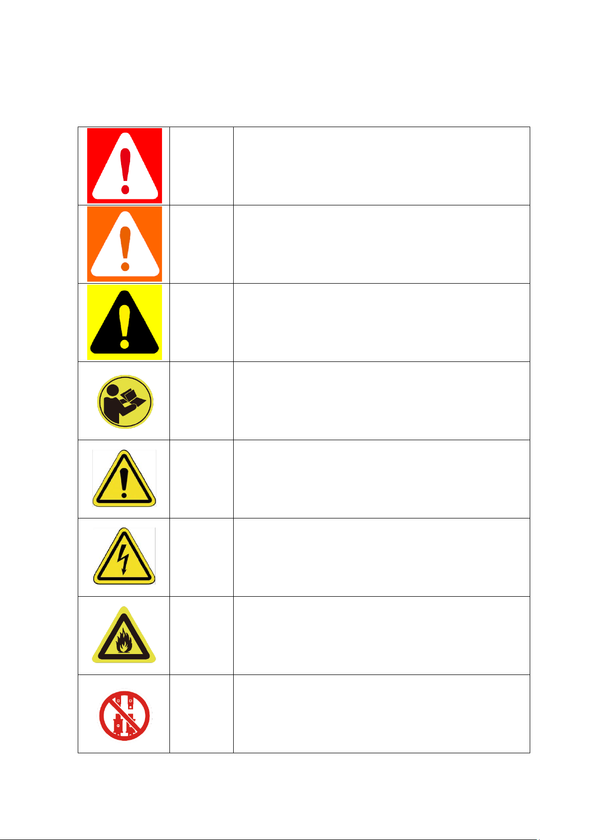
1.1 Symbol
Danger
Lethal voltage!
⚫ Battery strings will produce HIGH DC power and can
cause a lethal voltage and an electric shock.
⚫ Only qualified person can perform the wiring of the
battery strings.
Warning
Risk of battery system damage or personal injury
⚫ DO not pull out the connectors while the system is
working!
⚫ De-energize from all multiple power sources and verify
that there is no voltage.
Caution
Risk of battery system failure or life cycle reduces.
Symbol in
label
Read the product and operation manual before operating
the battery system!
Symbol in
label
Danger! Safety!
Symbol in
label
Warning electric shock!
Symbol in
label
Do not place near flammable material
Symbol in
label
Do not reverse connection the positive and negative.

3
Symbol
in label
Do not place near open flame
Symbol
in label
Do not place at the children and pet touchable area.
Symbol
in label
Recycle label.
Symbol
in label
Label for Waste Electrical and Electronic Equipment (WEEE)
Directive (2012/19/EU)
Symbol
in label
The certificate label for EMC.
Symbol
in label
The certificate label for Safety by TÜV SÜ D.
Symbol
in label
The certificate label for Safety by CSA.

4
Danger: Batteries deliver electric power, resulting in burns or a fire hazard when they are
short circuited, or wrongly installed.
Danger: Lethal voltages are present in the battery terminals and cables. Severe injuries or
death may occur if touch the cables and terminals.
Warning: DO NOT open or deform the battery module, otherwise the product will be out of
warranty scope
Warning: Whenever working on the battery, wear suitable personal protective equipment
(PPE) such as rubber gloves, rubber boots and goggles.
Warning: Force-H1-V2 system working temperature range: 0 ℃ ~ 50 ℃ ; Optimum
temperature: 18℃~28℃. Out of the working temperature range may cause the
battery system over / low temperature alarm or protection which further lead to
the cycle life reduction as well as. It will affect the warranty terms as well.
Warning: For battery installation, the installer shall refer to NFPA70 or similar local
installation standard for operation.
Caution: Improper settings or maintenance can permanently damage the battery.
Caution: Incorrect inverter parameters will lead to a further faulty/damage to battery.
Reminding
1) It is very important and necessary to read the user manual carefully (in the accessories)
before installing or using battery. Failure to do so or to follow any of the
instructions or warnings in this document can result in electrical shock, serious
injury, or death, or can damage battery, potentially rendering it inoperable.
2) If the battery is stored for long time, it is required to charge them every six months, and
the SOC should be no less than 90%;
3) Battery needs to be recharged within 12 hours, after fully discharged;
4) Do not expose cable outside;

5
1.2 Before Connecting
1) After unpacking, please check product and packing list first, if product is damaged or lack
of parts, please contact with the local retailer;
2) Before installation, be sure to cut off the grid power and make sure the battery is in the
switched-off mode;
3) Wiring must be correct, do not mistake the positive and negative cables, and ensure no
short circuit with the external device;
4) It is prohibited to connect the battery and AC power directly;
5) Battery system must be well ground and the resistance must be less than 100mΩ;
6) Please ensured the electrical parameters of battery system are compatible to related
equipment;
7) Keep the battery away from water and fire.
1.3 In Using
1) If the battery system needs to be moved or repaired, the power must be cut off and the
battery is completely shut down;
2) It is prohibited to connect the battery with different type of battery.
3) It is prohibited to put the batteries working with faulty or incompatible inverter;
4) It is prohibited to disassemble the battery (QC tab removed or damaged);
5) In case of fire, only dry powder fire extinguisher can be used, liquid fire extinguishers are
prohibited;

6
2. System Introduce
2.1 Product Introduce
Force-H1-V2 is a high voltage battery storage system based on lithium iron phosphate battery,
which is one of the new energy storage products developed and produced by Pylontech. It can
be used to support reliable power for various types of equipment and systems. Force-H1-V2
enabled multiple strings` parallel operation feature, which provide tremendous flexibility in
system design and configuration. Force-H1-V2 is especially suitable for those application scenes
which required high power output, limited installation space, restricted load-bearing and long
cycle life.
2.2 Specifications

7
2.2.1 System Parameter
2.2.1.1 Single group system parameter
Product Type
Force-H1-V2
Cell Technology
Li-iron (LFP)
Battery System
Capacity(kWh)
7.10
10.65
14.20
17.76
21.31
24.86
Battery System
Voltage (Vdc)
96
144
192
240
288
336
Battery System
Capacity (AH)
74Ah
Battery Controller
Name
FC0500-40S-V2
Battery Module Name
FH48074
Battery Module
Quantity(pcs)
2 3 4 5 6
7
Battery Module
Capacity(kWh)
3.552
Battery Module
Voltage (Vdc)
48
Battery Module
Capacity (AH)
74
Battery System Charge
Upper Voltage (Vdc)
108
162
216
270
324
378
Battery System Charge
Current (Amps,
Standard)
14.8
Battery System Charge
Current (Amps,
Normal)
37
Battery System Charge
Current (Amps,
Max.@15s)
42
Battery System
Discharge Lower
Voltage (Vdc)
87
130.5
174
217.5
261
304.5
Product Type
Force-H1-V2

8
Battery System
Discharge Current
(Amps, Standard)
14.8
Battery System
Discharge Current
(Amps, Normal)
37
Battery System
Discharge Current
(Amps, Max.@15s)
42
Short circuit rating
(Amps)
<4000
Efficiency (%)
96
Depth of Discharge
(%)
95
Dimension(W*D*H,
mm)
600*380*
530
600*380*
700
600*380*
870
600*380*
1040
600*380*
1210
600*380*
1380
Communication
CANBUS/Modbus RTU
Protection Class
IP55
Weight (kg)
86
122
158
194
230
266
Operation Life (Years)
15+
Operation
Temperature(℃)
0~50℃
Storage
Temperature(℃)
-20~60℃
Altitude(m)
<2000
Humidity
5~95%
Product Certificate
VDE-AR-E 2510-50, IEC62619, IEC63056, IEC62040-1,
2014/53/EU(RED),UL1973
Transfer Certificate
UN38.3
1) Battery Controller
Dimensions (W*D*H)
600×380×150mm
2) Battery Module
Dimensions (W*D*H)
600×380×170mm
3) Battery bottom
base Dimensions
(W*D*H)
600×380×40mm

9
2.2.1.2 Multi-groups system parameter (Max. 6 groups per system)
For multi-groups operation, please make sure the battery type in the whole system is the same,
please make sure the battery amount of each group is the same.
Product Type
Force-H1-V2 in multi-groups
Battery System Voltage(Vdc)*
96/144 / 192 / 240 / 288 / 336
Battery System group amount(pcs)
2 3 4 5 6
Battery System capacity (AH)
148
222
296
370
444
Battery System Operation
Current(Amps, Standard)
29.6
44.4
59.2
74
88.8
Battery System Operation
Current(Amps, Normal)
74**
111**
148***
185***
222***
Battery System Operation Current
(Amps, Max.@15s)
84**
126**
168***
210***
252***
P-Combiner-HV-3/6 Operation
Current (Amps, Normal)
50
100
P-Combiner-HV-3/6 Operation
Current (Amps, Max.@15s)
80
160
*The Battery System Voltage is varying depends on battery amount in serial per group.
**The current is based on BMS theoretical operation current to consider. If use P-Combiner-HV3 as the combiner box of the multi-groups` battery system wiring connection, the max.
continuous operation current is 50Amps, max. peak operation current is 80Amps for 15sec. for
the battery system. Please make sure the real operation current not exceed the combiner box
power rating.
***The current is based on BMS theoretical operation current to consider. If use P-CombinerHV-6 as the combiner box of the multi-groups` battery system wiring connection, the max.
continuous operation current is 100Amps, max. peak operation current is 160Amps for 15sec.
for the battery system. Please make sure the real operation current not exceed the combiner
box power rating.

10
2.2.2 Battery Module (FH48074)
Product Type
FH48074
Cell Technology
Li-ion (LFP)
Battery Module Capacity (kWh)
3.552
Battery Module Voltage (Vdc)
48
Battery Module Capacity (Ah)
74
Battery Module Serial Cell Quantity (pcs)
15
Battery Cell Voltage (Vdc)
3.2
Battery Cell Capacity (AH)
37
Dimension (W*D*H, mm)
600*380*170
Weight (kg)
36
Operation Life
15+Years
Operation Cycle Life
5,000
Operation Temperature
0~50℃
Storage Temperature
-20~60℃
Transfer Certificate
UN38.3

11
2.2.3 Control Module FC0500-40S-V2 (internal power supply)
Control Module (FC0500-40S-V2) Display Panel
LED Button
Short Press
Display the LED panel for 20sec.
Long Press 1
(between 5 to
10 seconds)
When status LED fast flashes blue ●, loss the button,
then it is 115200 baud rate of RS485.
When status LED fast flashes orange ●, loss the button,
then it is 9600 baud rate of RS485.
If a special protocol (except Pylontech Protocol), is
selected follow ‘Long Press 2’, then the baud rate
changing described here is ineffective.
Long Press 2
(more than
10sec)
Communication Protocol Selection, for details please
check with Pylontech service team

12
Status
2 colors, Blue and orange
Refer to [LED Indicators Instructions]
Battery Module Status
Blue solid
Normal
Orange solid
Individual module alarm or
protection. See trouble shooting
steps in section 5.1
System Capacity
System SOC
Each LED indicate 25%SOC
Indicate the system SOC.

13
LED Indicators Instructions
Condition
Note
Self-checking
Blue, Flashing
All flashing
Self-checking
failure
Orange, Slow flashing
Off
Battery Module Status
off. See trouble
shooting steps in
section 5.1
Black start
success
Blue, fast flashing
Off
Black start failure
Orange, Fast flashing
Off
See trouble shooting
steps in section 5.1
Communication
Lost or BMS error
Orange, solid
Indicate SOC, blue,
solid
See trouble shooting
steps in section 5.1
Idle
Blue, slow flashing
Indicate SOC, blue,
solid
Charge
Blue, solid
Indicate SOC, blue,
solid
Floating charge
Blue, solid
All flashing, horse race
lamp
Discharge
Blue, flashing
Indicate SOC, blue,
solid
System sleep
Blue, flashing
Off
Battery module status
off
Remark: Slow flashing: 2.0s ON/1.0s OFF. Flashing 0.5s ON/0.5s OFF.
Fast flashing: 0.1s ON/0.1s OFF.

14
Control Module (FC0500-40S-V2) Cable Panel
Power Switch
ON: main breaker ON, able to turn on battery system by start button.
OFF: system turn off completely, no power output.
Caution: When the breaker is tripped off because of over current or short circuit, must wait
more than 30min then can turn on it again, otherwise may cause the breaker damage.
Start Button
Start function: press more than 5sec until
the buzzer rings, to turn on controller.
Multi-groups start up sequence: please start up the last string(from communication
structure, the last slave) of battery system first, one by one to the first string which shall be
start up lastly. Details as below table
Communication Structure
Start-up Sequence
Master string
Last Start up
Slave string 1
5th Start up
Slave string 2
4th Start up (if has)
Slave string 3
3rd Start up (if has)
Slave string 4
2nd Start up (if has)
Slave string 5
1st Start up (if has)

15
Black start function: when system turn on, and relay is OFF, press more than 10sec, and relay
will turn on for 10 min without communication (depends on conditions).
Multi-groups Black Start: Only need perform black start operation on MASTER string, it will
close circuit for one of the strings within the system for 10mins. The slave string black start
function is being solely controlled by master string.

16
Wi-Fi
Manufacturer: Pylon Technologies Co., Ltd.
Address: Plant 8, No.505 Kunkai Road, JinXi Town, 215324 Kunshan City, Jiangsu Province,
PEOPLE'S REPUBLIC OF CHINA
Importer: XXXX (Located in installed country)
Address: XXXX (Located in installed country)
Wireless maximum output power: 20dBm
Operating frequency: 2412-2472MHz
Gain of antenna: Max 3dBi
Modulation system:
DBPSK/DQPSK/CCK(DSSS)
BPSK/QPSK/16QAM/64QAM(OFDM)
Modulating Repetition:
1Mbps/2Mbps/5.5Mbps/11Mbps (DSSS)
6Mbps/9 Mbps/12 Mbps/18 Mbps/24 Mbps/36 Mbps/48 Mbps/54 Mbps (OFDM)
MCS0~MCS7 (802.1 1n 20MHz)
Channel spacing:5MHZ
Type of antenna: 2.4G IPEX-SMA Antenna
For further connection method, please contact Pylontech service team
Power Terminal (+/-)
Connect power cables of battery system with Inverter.
During multi-groups operation, it can select P-Combiner-HV-3/6 as the combiner box between
inverter and batteries for max. 6strings of 100A continuous operation.
For more details of P-Combiner, please check with your distributor or Pylontech service team.
Communication Terminal (RS485 / CAN / RS232 / Link Port 0 / Link Port 1)

17
RS485 Communication Terminal: (RJ45 port) follow MODBUS 485 protocol, for
communication between battery system and inverter.
CAN Communication Terminal: (RJ45 port) follow CAN protocol, for communication between
battery system and inverter.
RS232 Communication Terminal: (RJ45 port) for manufacturer or professional engineer to
debug or service. The Pin1&2(12Vdc+/-) is dedicated for Sunny Boy Storage Enable Line
design.
Link0/Link1 Communication Terminal: (RJ45 port)for multi-groups operation using only,
connecting from first BMS Link 1 to second BMS Link 0, then from second BMS Link 1 to third
BMS link 0(if has), all the way to the last BMS Link 0. The BMS with Link Port 0 EMPTY is
defined as the Master string, which further communication with the inverter or upper
controller.
For multi-groups operation, please firstly make sure the communication cable between
multiple BMSs are properly connected between Link 1 and Link 0, before the start up.
Definition of RJ45 Port Pin
No.
CAN
RS485
RS232
1
---
---
12Vdc IN+*
2
GND
---
12Vdc IN-*
3
---
---
TX
4
CANH
---
---
5
CANL
---
---
6
---
---
RX
7
---
RS485A
---
8
---
RS485B
GND
* The Pin1&2(12Vdc IN+/ 12Vdc IN-) is dedicated for SMA Enable Line design.
2.3 System Diagram

18
3. Installation
3.1 Tools
The following tools are required to install the battery pack:

19
Wire Cutter
Crimping Modular Plier
Cable Ties
Screw Driver Set
Electric Screw Driver
Adjustable Wrench
Sleeve Piece
600VDC Multimeter
NOTE
Use properly insulated tools to prevent accidental electric shock or short circuits.
If insulated tools are not available, cover the entire exposed metal surfaces with available
insulated alternatives, except their tips, with electrical tape.
3.2 Safety Gear
It is recommended to wear the following safety gear when dealing with the battery pack
Insulated gloves Safety goggles Safety shoes

20
3.3 System Working Environments Checking
3.3.1 Cleaning
Before installation and system power on, the dust and iron scurf must be removed to keep a
clean environment.
The system cannot be installed in desert area without an enclosure to prevent from sand.
Danger: Battery module has active DC power at terminal all the time), must be careful to
handle the modules.
3.3.2 Ventilation
Force-H1-V2 system working temperature range: 0 ℃ ~ 50 ℃ ; Optimum temperature:
18℃~28℃.
There is no mandatory ventilation requirements for battery module, but please avoid of
installation in confined area. The aeration shall avoid of high salinity, humidity or
temperature.
Caution: Force-H1-V2 system is IP55 design. But please avoid frost or direct sunlight. Out of
the working temperature range will cause the battery system over / low temperature alarm
or protection which further lead to the cycle life reduction. According to the environment,
the cooling system or heating system should be installed if it is necessary.
3.3.3 Fire-extinguisher System
It must be equipped with fire-extinguisher system for safety purpose.
The fire system needs to be regularly checked to be in normal condition. Refer to the using
and maintenance requirements please follow local fire equipment guidance.
3.3.4 Grounding System
Before the battery installation must make sure the grounding point of the basement is stable
and reliable. If the battery system is installed in an independent equipment cabin (e.g.
container), must make sure the grounding of the cabin is stable and reliable.
The resistance of the grounding system must ≤100mΩ
3.3.5 Clearance
Minimum clearance to heat source is more than 2 meters.
Minimum clearance to battery module(rack) is more than 0.3 meters.

21
3.4 Handling and placement
Warning: The battery pile’s power terminals are high voltage DC. It must be installed in a
restricted access area;
Warning: Force-H1 is a high voltage DC system, operated by qualified and authorized
personnel only.
3.4.1 Handling and placement of the battery module
Single battery module is 36kg. If without handling tools must have more than 2 men to
handling with it.
3.4.2 Handling and placement of the base
The base is light, single person can handle with it.
3.4.3 Selection of installation sites
A. Force-H1-V2 system working temperature range: 0℃~50℃; Optimum temperature:
18℃~28℃. Do not place the battery system in direct sun light. It is suggested to build
sunshade equipment. In cold area the heating system is required.
B. Force-H1-V2 system must not be immersed in water. Cannot be placed the battery base
in rain or other water sources. As a suggestion, the base’s height shall >300mm above the
ground.
C. The base’s weight capacity should support the weight of whole battery system
(130~300kg).
D. Force-H1-V2 system bust be installed on fixed ground.

22
3.4.4 Packing list
FC0500-40S-V2 Battery Controller
Item
Description
Set 1 FC0500-40S-V2 Battery Controller
1 2 Force-H1 basement (600*380*40, mm)
1 3 EPE foam
3 4 3M black external communication cable (RJ45)
2 5 3M DC+ red external power cable (8AWG)
1 6 3M DC- black external power cable (8AWG)
1 7 1M yellow-green grounding cable (10AWG)
1 8 M4 screws for fixing brackets
20 9 M8 bolts for fixing basement
4
10
571.5mm bracket
For up to 3 battery modules installation
2
11
701.5mm bracket for fix ≤ 4 battery modules
In combine use with 571.5mm bracket for up to 7 modules installation;
see below installation picture;
2
12
Product Manual
1
13
Warranty card
1
14
1.5M black internal communication cable (RJ45)
1
FH48074 Battery Module
1
FH48074 battery module
1 2 EPE foam
2
No additional kits needed for Force-H1-V2 installation.

23
3.4.5 Mounting and installation of the base
The base must be fixed installed on the basement with 4pcs M8×80 foundation bolts.
Battery rack basement holes bitmap (unit: mm):
3.4.6 Battery Modules and Control Module (BMS) pile up
Handle above the red marked edgings of the both side of these battery modules and control
module (BMS).
Caution: If hands under this red marked side, hands will get hurt.

24
Danger: when battery is connected together with the base the internal socket still have
high voltage DC power from serial connected battery modules (battery module can’t be
turned off).
3.4.7 Installation of the metal bracket for the system
In control module’s package has 2pcs short and 2pcs long metal
brackets.
Fix these metal brackets at the both back side corners.

25

26 27

3.4.8 Locking of the control Module’s fix screw of left and right side

28
3.5 Cables connection
Attention:
Danger: The battery system is high voltage DC system. Must make sure the grounding is fixed
and reliable.
Danger: All the plugs and sockets of the power cables must be not reverse connection.
Otherwise it will cause personal injury.
Danger: No short circuit or reserved connection of the battery system’s positive and negative
port.
Caution: Wrong communication cables connection will cause the battery system failure.

29
3.5.1
Grounding
The Force-H1-V2 modules’ grounding cable on the grounding point (above the right side of
top metal bracket screw or beside the both side of screw 1).
Grounding cable must ≥10AWG. The cable shall be copper with yellow-green color.

30
3.5.2 Cables
Note: Power cable uses water-proofed connectors.
To disconnect, a special tool is required. Do not pull out directly
Note: Communication cable uses RJ45 connector and water-proofed cover(M19-RJ45)
matched with controller connection port.

31

32
3.5.3 Multi-groups battery wiring diagram
Wiring diagram of 3 strings` system
*It`s suggested to use P-Combiner-HV-3 for upto 3 strings, max. 50Amps synchronized continuous
operation.
*It`s not allowed to use the P-Combiner-HV-6 or similar concept of multi-groups connection
method in case the multiple groups` of battery are operation independently.
Make sure to have the D+ & D- plug into the combiner box properly.
Wiring diagram of 6 strings` system

33
*It`s suggested to use P-Combiner-HV-6 for upto 6 strings, max. 100Amps synchronized
continuous operation.
*It`s not allowed to use the P-Combiner-HV-6 or similar concept of multi-groups connection
method in case the multiple groups` of battery are operation independently.
Make sure to have the D+ & D- plug into the combiner box properly.
Wiring diagram of master/slave communication cable
The communication for master/slave string connection shall use a 8pin pin-pin RJ45 cable,
connecting from first BMS Link 1 to second BMS Link 0, then from second BMS Link 1 to third BMS
link 0 (if has), all the way to the last BMS Link 0. The BMS with Link Port 0 EMPTY is defined as the
Master string, which further communication with the inverter or upper controller.
The slave strings` CAN/RS485 Port is ineffective in this case.

34
3.5.3 System turns on
3.5.3.1 Single group system turns on
Warning: Double check all the power cables and communication cables. Make sure the
voltage of the inverter/PCS is same level with the battery system before connection.
Check all the power switches are OFF.
System turns on step:
1) Check all cables are connected correctly. Check grounding is connected.
2) If necessary, turn on the switch at inverter`s battery side or between inverter and
battery. If possible, turn on AC or PV power source to wake up inverter.
3) Open protect cover of Power switch. And turn on power switch.
4) Press start button for at least 5 seconds or until buzzer rings. Battery takes 10-30s
for self-checking.
If inverter is turned on by AC or PV source, then most inverter can setup communication with
BMS automatically, in this case, the BMS will close relay and system is ready for
work.
If inverter needs battery power to turn on, then check the LED of battery shall be:
Status: Orange, solid
SOC: blue, solid
In this case, press the Start button for at least 10s, till the Status lighting Blue and fast flashing,
then battery will black start to support inverter and after inverter turned on and
set up communication, then BMS is ready for work.
If the battery has been configured to a different communication protocol (follow LED Long
Press 2 guidance), please make sure to select the correct protocol and restart BMS
to enable the communication with inverter.
Caution: When the breaker is tripped off because of over current or short circuit, must wait
after 10min to turn on it again, otherwise may cause the breaker damage.

35
Warning: If has failure during the self-check, must debug the failure then can start next step.
If the “STATUS” lamp shows orange from beginning, it means there has some
failure in the battery string, the Power Relays in BMS will open, must debug at
first.
Note: The LED lamp will be off in 20sec without any operation.
Caution: During first time power on, the system will require to do fully charge progress for
SOC calibration purpose.
Caution: it is suggested to fully charge the whole Battery Energy Storage System (BESS) first
after installation or after long time storage without charging. Depending on the
soc level, there will be a regularly (3 month) fully charge requesting during
continuous operation as well, it will be handled automatically by the
communication between BESS and external device.

36
3.5.3.2 Multi-groups system turns on
Warning: Double check all the power cables and communication cables. Make sure the
voltage of the inverter/PCS is same level with the battery system before connection. Check
all the power switches are OFF.
System turns on step:
1) Check all cables are connected correctly. Especially the Link 1 / Link 0 between master
and slave strings. Check grounding is connected.
2) If necessary, turn on the switch at inverter`s battery side or between inverter and battery.
If possible, turn on AC or PV power source to wake up inverter.
3) Open protect cover of Power switch. And turn on power switch of all the strings.
4) From the last string, press start button for at least 5 seconds or until buzzer rings for
start-up. Then further turn on each string one by one follow below table, the start-up interval
between each strings shall less than 30sec.:
Communication Structure
Start-up Sequence
Master string
Last Start-up
Slave string 1
5th Start-up
Slave string 2
4th Start-up (if has)
Slave string 3
3rd Start-up (if has)
Slave string 4
2nd Start-up (if has)
Slave string 5
1st Start-up (if has)
5) Battery system takes 30sec for self-checking, after all strings start-up.
If inverter is turned on by AC or PV source, then most inverter can setup communication with
BMS automatically, in this case, the BMS will close relay and system is ready for work.
If inverter needs battery power to turn on, then check the LED of battery shall be:
Status: Orange, solid
SOC: blue, solid
In this case, press the Start button for at least 10s, till the Status lighting Blue and fast flashing,
then battery will black start to support inverter and after inverter turned on and set up
communication, then BMS is ready for work.

37
3.5.4 System turns off
When failure or before service, must turn the battery storage system off:
(1) Turn off inverter or power supply on DC side.
(2) Turn off the switch between PCS and battery system.
(3) Turn off the “Power Switch” of the all BMSs.
Caution: Before replace the battery module for service, must charge/discharge the existing
battery module voltage similar to the replacement. Otherwise the system need
long time to do the balance for this replaced battery module.
Caution: When restart is required for any troubleshooting steps, please make sure to
restart the entire system (every BMS within the system). Please do not only
restart partially of the BMS within the system which will rise up further error.
NOTE
After installation, DO NOT forget to register online for full warranty:
www.pylontech.com.cn/service/support

38
4. System Debug
This system debug is for BESS system (Battery Energy Storage System). BESS system can’t do the
debug itself. It must operation with configured inverter, UPS, PCS and EMS system together.
Debug Step
Content
Prepare of debug.
Turn on the BESS system, refer to chapter 3. Before turn on the
whole BESS system turn on the load is not allowed!
Remark: Except the BESS, if other equipment have its own system
turn on step, must follow the operation manual.
Working together with
inverter
1) Check the communication cable connection and make sure the
cable order on battery and inverter side are matched. All undefined
pin are suggested to be empty.
2) Check the baud rate of inverter. The default of battery CAN is
500kbps, MODBUS 485 is 9600bps. If necessary, change the baud
rate of RS485.
3) Check the terminal resistance CAN 120 Ω, 485 120 Ω
4) If necessary, check the setting on inverter or control box has
right parameter and brand of battery. And check the information of
BESS shown on inverter is correct.

39
5. Maintenance
5.1 Trouble Shooting:
Danger: The Force-H1-V2 is a high voltage DC system, operated by qualified and authorized
person only.
Danger: Before check the failure, must check all the cables connection and the BESS system
can turn on normally or not.
Check the environment first
No
Problem
Possible Reason
Solution
1
No power output, no
led on.
Press start button too short.
To turn on, at least 5s
To black start, at least
10s.
The button battery in controller is
missing or failure.
The power supply in controller is
failure
Change the controller
module.
The battery voltage is too low.
Make sure at least 3
battery modules.
The connector of base is failure
The base is not
connected or change the
base
2
After turned on, status
LED slow flashing
orange. Others off.
Self-checking failure.
DC side has a voltage, but voltage
difference with the battery
system is higher than 20V.
Make sure no DC voltage
or set correct DC voltage
before press start
button.
Then follow turn on
process.
BMS internal failure.
Use debug tool to
further analysis or
change the controller
module.
3
Status LED fast flashing
orange, others off.
The time interval after last time
black start is too short.
Wait more than 5
minutes and try black
start again.
The battery system under error
condition such as: temperature or
current protection or other error,
thus do not response black start.
Make sure no other
protection factor. Or use
debug tool to further
analysis.

40
4
Buzzer rings continue
Relay adhesion or failure.
Completely disconnect
battery system with any
DC source then make a
restart. If problem
remain, then swap the
controller.
5
Status LED solid
orange. Battery module
LED blue solid.
Communication lost with inverter
Check the
communication cable
PIN and wiring whether
is correctly.
Over current protection.
Check DC side. And wait
until BMS release
protection.
Controller failure.
Use debug tool to
further analysis or
change the controller
module. Or use debug
tool.
6
Status LED solid
orange. Battery module
exists LED in orange
solid
Over/ under temperature
protection.
Check environment
temperature. And wait
BMS release.
Over voltage protection.
Check DC charge voltage
setting or wait BMS
release.
Under voltage protection.
Use black start function,
and then charge the
system.
Battery module BMS failure
Use debug tool to
further analysis or
change the battery
module.
7
All LED blue but no
output.
Fuse fusing
Change the controller
module
8
Other failure
Cell failure or electrical board
failure. Or failure need debug tool
for further debug.
Can’t find out failure
point or can’t check.
Please contact with
distributor or Pylontech.
Once a certain failure detected following the trouble shooting steps, shut down the battery string
first before replacement to avoid further over discharge to the system due to the selfconsumption.

41
5.2 Replacement of main component
Danger: The Force-H1-V2 is a high voltage DC system, operated by qualified and authorized
person only.
Danger: Before replace the main component must shut off the maintenance battery string’s
power. Must confirm the D+ and D- terminal are without power. The turn off
progress refer to chapter 3.6.5.
5.2.1 Replacement of Battery Module
5.2.1.1 Charge existing module to full (SOC 100%). Make sure new battery
module is 100% as well.
5.2.1.2 Turn off the whole battery string’s power. Must confirm the D+ and D-
terminal are without power. The turn off progress refer to chapter 3.5.4.
5.2.1.3 Dismantle D+ and D- Power Cable, Communication Cable and
Grounding Cable.
5.2.1.4 Dismantle the control Module’s fix screw of left and right side. And dismantle the fix
metal brackets.
5.2.1.5 Move the control module and each battery module one by one.
Danger: when battery is
connected together with the
base the internal socket still
have high voltage DC power
from serial connected battery
modules (battery module
can’t be turned off).

42
Handle above the red marked edgings of the both side of these battery modules and control
module (BMS).
Caution: If hands under this red marked side, hands will get hurt.
Warning: Single battery module is 35kg. If without handling tools must more than 2 men to
handling with it.
5.2.1.6 Pile up the new battery module. And pile up the battery modules and control
module up again.
5.2.1.7 Install back the control Module’s fix screw of left and right side. And install back the
fix metal brackets.
5.2.1.8 Install back Grounding Cable, Communication Cable and the D+ and D- Power Cable.
5.2.1.9 Turn on this battery string. Refer to chapter 3.5.3.

43
5.2.2 Replacement of Control Module (BMS)
5.2.2.1 Turn off the whole battery string’s power. Must confirm the D+ and D- terminal are
without power. The turn off progress refer to chapter 3.5.4.
5.2.2.2 Dismantle D+ and D- Power Cable, Communication Cable and Grounding Cable.
5.2.2.3 Dismantle the control Module’s fix screw of left and right side. And dismantle the fix
metal brackets.
5.2.2.4 Remove the control module.
Danger: when battery is connected
together with the base the internal
socket still have high voltage DC
power from serial connected battery
modules (battery module can’t be
turned off).
5.2.2.5 Pile up the new control module.
5.2.2.6 Install back the control Module’s fix screw of left and right side. And Install back the fix
metal brackets.
5.2.2.7 Install back Grounding Cable, Communication Cable and the D+ and D- Power Cable.
5.2.2.8 Turn on this battery string. Refer to chapter 3.5.4.

44
5.3 Battery Maintenance
Danger: The maintenance of battery must be done by qualified and authorized personnel
only.
Danger: Some maintenance items must turn off at first.
5.3.1 Voltage Inspection:
[Periodical Maintenance] Check the voltage of battery system through the monitor system. Check
the system whether exist abnormal voltage or not. For example: Single cell’s voltage is abnormal
high or low.
5.3.2 SOC Inspection:
[Periodical Maintenance] Check the SOC of battery system through the monitor system. Check
the battery string whether exist abnormal SOC or not.
5.3.3 Cables Inspection:
[Periodical Maintenance] Visual inspect all the cables of battery system. Check the cables has
broken, aging, getting loose or not.
5.3.4 Balancing:
[Periodical Maintenance] The battery strings will become unbalance if long time not be full
charged. Solution: every 3 month should do the balancing maintenance (charge to full), normally
it will been done automatically by the communication between system and external device.
5.3.5 Output Relay Inspection:
[Periodical Maintenance] Under low load condition (low current), control the output relay OFF
and ON to hear the relay has click voice, that’s mean this relay can off and on normally.
5.3.6 History Inspection:
[Periodical Maintenance] Analysis the history record to check has accident (alarm and protection)
or not, and analysis its reason.
5.3.7 Shutdown and Maintenance:
[Periodical Maintenance]
Some system function must be maintenance during the EMS restart, it is recommended to
maintenance the system every 6 months.
5.3.8 Recycle
NOTE
Damaged batteries may leak electrolyte or produce flammable gas.
In case a damaged battery needs recycling, it shall follow the local recycling regulation (ie.
Regulation (EC) Nº 1013/2006 among European Union) to process, and using the best available
techniques to achieve a relevant recycling efficiency.
6. Remarks
Storage recommendation

45
For long-term storage (more than 3 months), the battery cells should be stored in the
temperature range of 5~45℃, relative humidity <65% and contains no corrosive gas
environment.
The battery module should shelfed in range of 5~45℃, dry, clean and well ventilated
environment. Before storage the battery should be charged to 50~55% SoC;
It is recommended to active the chemical (discharge and charge) of the battery every 3 months,
and the longest discharge and charge interval shall not exceed 6 months.
Caution: If not follow the above instructions for long term store the battery, The cycle life
will have relative heavily reduction.
Capacity expansion
A new battery module can be add onto an existing system at any time. Please make sure the
existing system is being fully charged before add on a new module. In a serial connection
system, the new module, even has a higher SOH, will follow the system worst SOH condition
module to perform.

46
7. Shipment
Battery module will pre-charged to 100%SOC or according to customer requirement before
shipment. The remaining capacity of battery cell, after shipment and before charge, is determined
by the storage time and condition.
1. The battery modules meet the UN38.3 certificate standard.
2. In particular, special rules for the carriage of goods on the road and the current dangerous
goods law, specifically ADR (European Convention on the International Carriage of Dangerous
Goods by Road), as amended, must be observed.
Any further questions, please contact Pylontech: service@pylontech.com.cn

47
Annex 1: Installation and System Turn ON Progress List
Tick after
completion
No
.
Item
Remark
☐
1
The environment is meeting all technical requirements.
3.3.1 Cleaning
3.3.2 Temperature
3.3.3 Fire-extinguisher System
3.3.4 Grounding System
3.3.5 Clearance
Refer to chapter
3.3
☐
2
Selection of installation sites.
Refer to chapter
3.4.3.
☐
3
Battery base is installed follow the technical
requirements.
Refer to chapter
3.4.4.
☐
4
Battery modules installation.
Refer to chapter
3.4.5.
☐
5
Battery system are fixed.
Refer to chapter
3.4.6.
☐
6
Control Module (BMS) and Battery Module are
installed well.
Refer to chapter
3.4.7.
☐
7
Connect D+ and D- between BMS to the inverter/PCS
or confluence cabinet.
Refer to chapter
3.5.2.
☐
8
Connect the grounding cable.
Refer to chapter
3.5.1.
☐
9
Double check every power cables, communication
cables, grounding cable installed well.
Refer to chapter
3.5.2 and 3.5.1.
☐
10
Switch the external power or inverter/PCS on, ensure
all the power equipment can work normally.
Refer to chapter
3.6.4.
☐
11
The first installation should do full charging progress
automatically.
If the status LED of BMS turns to blue, it means this
battery string is operation.

48
Annex 2: System Turn OFF Progress List
Tick after
completio
n
No.
Item
Remark
☐
1
Soft-off the inverter through inverter’s control panel.
Refer to chapter
3.5.4.
☐
2
Turn off the switch between inverter and this battery
string (Force-H1), or turn off the power switch of
inverter, to make sure no current through this battery
string.
Refer to chapter
3.5.4.
☐
3
Turn off the “Power Switch” of the BMS.
Refer to chapter
3.5.4.

49

50

51

Pylon Technologies Co., Ltd.
No. 73, Lane 887, ZuChongzhi Road, Zhangjiang Hi-Tech Park
Pudong, Shanghai 201203, China
T+86-21-51317699 | F +86-21-51317698
E service@pylontech.com.cn
W www.pylontech.com
 Loading...