

Page 1

Extra 2000
Lithium-Iron Phosphate Battery Backup
Product Manual
Information Version: 1.2
Page 2

LEGAL NOTICES
Copyright of Pylon Technologies Co., Ltd. Enjoin from abstracted reproduced or translated
by any unit or individual in any way without the written permission.
Rights reserved.
The trademarks of Pylon Technologies Co., Ltd are and .
The names and logos of products from Pylontech are exclusive belongs to Pylon
Technologies Co., Ltd, proprietary marks or registered trademarks. Other products or
company names mentioned in this manual may be belonging to trademarks of their
respective owners or tradenames. Without the prior written consent of the Pylontech or
third party trademarks or owners of tradenames, this manual does not confer the li
or right by the reader to use any mark appeared on this manual in any way.
This product accord with the design requirements of environmental protection and
personal security, product storage, using and disposal should be in accordance with
product manuals, relevant contract and relevant national laws.
When appeared product updates or technical changes, you can send via website of
Pylontech for the latest information, URL:
the product improvements or technical change in other way.
Information Version: V1.2
Information Number: MKT-EXSC1-130410
http ://www.pylontech.com.cn, without notice If
cense
Revise History
Revision NO. Revision
1.0 2010.9.10
1.1 2012.5.20
1.2 2013.4.10
Date
Revision
First Release
Product Updates
Product Updates
Reason
Page 3

Introduction
Manual Explains
Extra 2000 (V1.2) lithium iron phosphate battery is external backup power module for
48V devices. Under normal mains power, the power supply provides energy for user
equipment and charging the battery; when the power supply interrupted, the battery
provides energy for equipment.
Extra 2000 Product Manual exposited the basic processes and methods of the device,
includes structure, parameters, installation and operation. The main contents of this
manual are follows:
Chapter Abstract
Chapter 1 Introduction Main application and features of Extra 2000
Chapter 2 Structure and
Parameters
Chapter 3 Installation and
Collocation
Chapter 4 Maintenance and
Troubleshooting
External structure, panel descript io n, mana gem ent mod ule
parameters and others of Extra 2000.
Product installation, network usage and requires attention in
installation process of Extra 2000
Common operating status descriptions and Troubleshooting of
Extra 2000
Safety Instructions
This device only be installed, operated and maintained by peop le who professi onal traine d
and qualified. In the process of installation, operation and maintenance, local safety
regulations and related procedures must be complied, or it may result injury or equipment
damage. Safety precautions mentioned in manual only as a supplement for local safety
regulations. Pylontech does not assume any responsibility for breaching commo n security
operation or equipment safety standards.
Symbols
The following format described some contents need attention for Extra 2000
Note: If warning ignored, the product may malfunction.
Pylon Technologies Co., Ltd. Confidential Proprietary 1
Page 4

Catalogue
Extra 2000
Lithium Iron Phosphate Battery Backup
1 Information ..................................................................................................................... 1
1.1 Information ---------------------------------------------------------------------------------------- 1
1.2 Product Features -------------------------------------------------------------------------------- 1
2 Structure and Parameter ................................................................................................ 2
2.1 Equipment Structure ---------------------------------------------------------------------------- 2
2.1.1 Equipment Model ................................................................................................ 2
2.1.2 Equipment Front Interface I nst ruct ion ................................................................. 2
2.2 Battery Management System(BMS) ---------------------------------------------------- 4
2.2.1 V oltage Protection Function ................................................................................ 4
2.2.2 Current Protection Function ................................................................................ 4
2.2.4 Other Protection Function ................................................................................... 5
2.3 Charge Parameters ----------------------------------------------------------------------------- 5
2.4 Discharge Parameters ------------------------------------------------------------------------- 6
3 Installation and Configuration ........................................................................................ 7
3.1 Installation Preparation ------------------------------------------------------------------------- 7
3.1.1 Environmental Require ment s.............................................................................. 8
........................................................................................................................ 1
................................................................. 1
3.1.2 Tools and Information ......................................................................................... 8
3.1.3 Technical Preparation ......................................................................................... 9
3.1.4 Unpacking ......................................................................................................... 10
3.1.5 Project Coordination.......................................................................................... 10
3.2 Equiment Installation ---------------------------------------------------------------------------- 10
3.2.1 Mechanical Installation ...................................................................................... 11
3.2.2 Electrical Installation ......................................................................................... 11
4 Using, Maintenance and Troubleshooting ................................................................... 16
4.1 Alarm Description and Processing -------------------------------------------------------- 16
4.1.1 The Alarm and Countermeasure Influence System Output.............................. 16
4.1.2 The Alarm and Countermeas ure D o Not I nf lu ence System Output ................. 16
4.2 Common Fault Analysis and Solutions --------------------------------------------------- 17
Pylon Technologies Co., Ltd. Confidential Proprietary 2
Page 5

Catalogue of Diagrams
Figure 2-1 Extra 2000 Front Interface Diagram ................................................................ 3
Figure 3-1 Schematic of Installation Process ................................................................... 9
Figure 3-2 Schematic Device Fixed to the Cab inet ........................................................ 13
Figure 3-3 Multiple Batteries in Parallel Pow er Line Connection Diagram ..................... 14
Figure 3-4 Connection Interface between Bat t ery and Load Equipment of DC Backup 15
Figure 3-5 Battery and Switch Power Connection Diagram ........................................... 16
Figure 3-6 Cascading of Multiple Batteries in Parallel Network Schematic ................... 17
Pylon Technologies Co., Ltd. Confidential Proprietary 3
Page 6

Catalogue of Table
Table 2-1 Extra 2000 Equipment Model ............................................................................ 2
Table 2-2 Definition of RS232 Port P in ............................................................................. 3
Table 2-3 ADD Switch ....................................................................................................... 4
Table 2-4 LED Indicators Instruct ions ............................................................................... 4
Table 2-5 Protection Function Parameters ....................................................................... 6
Table 2-6 Charging Parameters ........................................................................................ 7
Table 2-7 Discharging Parameters .................................................................................... 7
Table 3-1 Tools and Meters ............................................................................................. 10
Table 3-2 Installation Steps ............................................................................................. 12
Table 4-1 Major Alarm and Protection ............................................................................. 18
Table 4-2 Secondary Alarm ............................................................................................. 19
Table 4-3 Common Faults and Solut ion s ........................................................................ 19
Pylon Technologies Co., Ltd. Confidential Proprietary 4
Page 7

Extra2000LithiumIronPhosphateBatteryBackupManual
1 Introduction
1.1 Introduction
Extra 2000 lithium iron phosphate battery backup is new energy storage battery
products developed and produced by Pylontech according to market demand, it
can be used to provide reliable backup power for various types of communication
operators of 48V power supply equipments. Extra2000 is especially suitable for
operating environment of high temperature, limited installation space, light
load-bearing and long cycle life applications.
Extra 2000 has built-in BMS battery management system. Under normal
circumstances, the main power provides energy for user equipment and charging
bat
tery; when the power supply interrupted, the battery provides energy for user
equipment. Multiple batteries can be connected for larger capacity in parallel for
longer duration backup requirements.
1.2 Product Features
Extra 2000 product from Pylontech is using lithium iron phosphate as cathode
material, with BMS for effective management of cells. The system has the following
characteristics:
The battery is non-toxic, non-polluting and environmentally friendly;
Cathode material is made from LiFePO4 which has safety performance and long
ycle life;
c
Battery management system (BMS) has protection function for status of
over-discharge, over-charge, over-current and high temperature;
The system can automatically manage charge and discharge status and balance
current and voltage of each single cell;
The centralized monitoring module is intelligent designed with three remote
Pylon Technologies Co., Ltd. Confidential Proprietary 1
Page 8

Extra2000LithiumIronPhosphateBatteryBackupManual
functions of test, signal and control;
Flexible configuration achieved that several battery modules can be in parallel to
expand capacity and extend backup duration;
Adopted self-cooling mode rapidly reduced system entire noise;
Battery has less self-discharge, without charge up to 10 months; no memory effect,
can be floating charge and discharge;
Worki
S
ng temperature range is from -10 ℃ to 55 ℃, with excellent discharge
performance and cycle life in h
mall size and light weight, standard of 19-inch embedded design, comfortable
installation and maintenance;
igh temperature;
2 Structure and Parameter
2.1 Equipment Structure
2.1.1 Equipment Model
Table2-1 Extra 2000 Equipment Model
Product
Model
Series
Extra
Extra 2000 48V 50Ah 436×370×132mm 30kg
Series
Rated
Voltage
Rated
Size Weight
Capacity
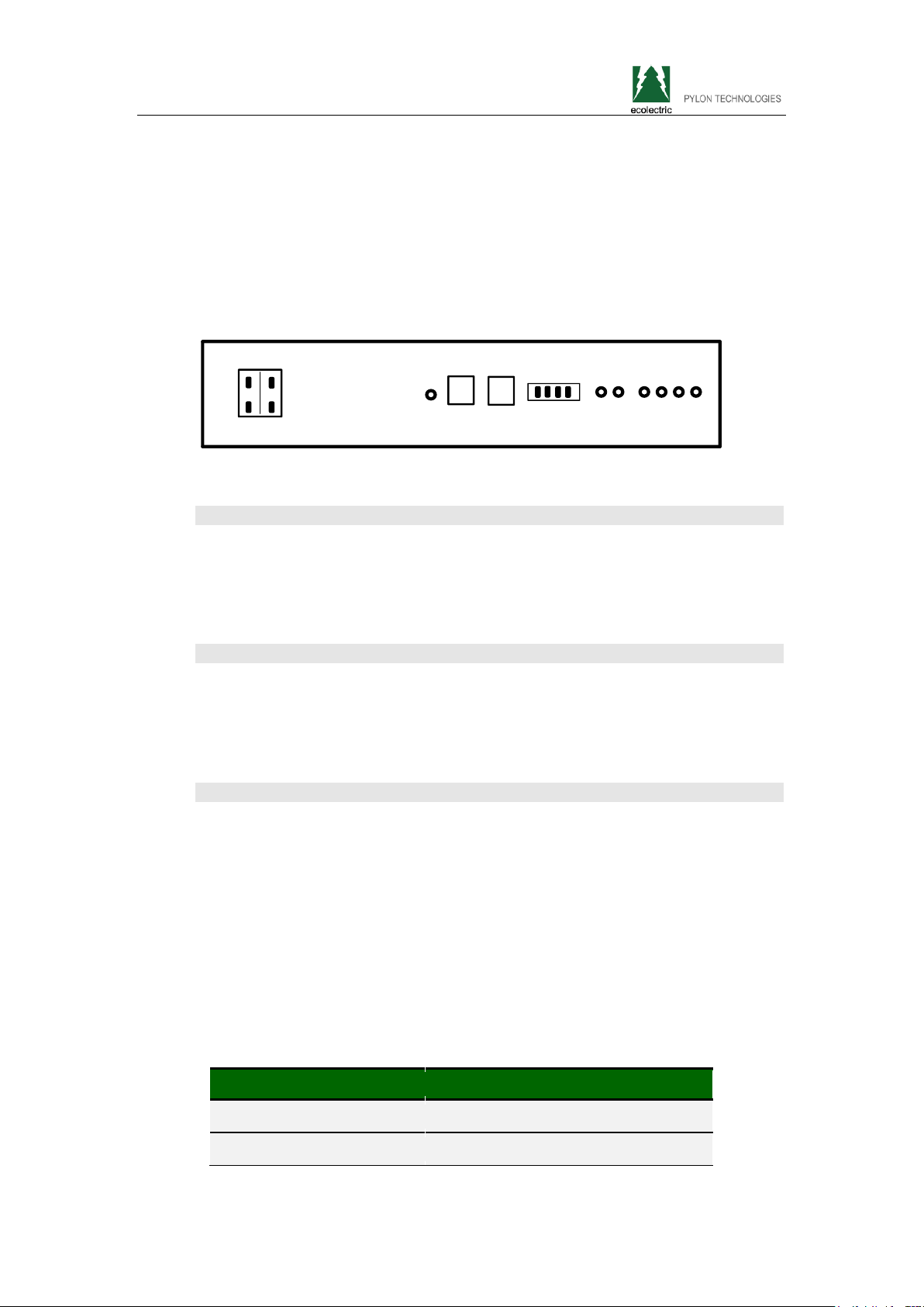
2.1.2 Equipment Front Interface Instruction
This section details the front panel of the interface functions.
Pylon Technologies Co., Ltd. Confidential Proprietary 2
Page 9
e
d
Extra2000LithiumIronPhosphateBatteryBackupManual
Figure 2-1 Sketch of Extra 2000 Product Front Interface
Interface Protocol Standard: YD/T 1363.3-2005 " Part 3: Front intelligent devic
protocol of Communications Authority (Station) Power Supply, Air-conditioning an
Environment Centralized Monitoring and Management Systems".
1
2
4
3
5
ON
OFF
6
87
Power Port (1)
Power cord connection: the same function of two power interface in parallel.
Each interface from top to bottom is anode and cathode. For each single cell,
any interface can achieve charging and discharging function.
Reset (2)
Shut down button: When the battery is in storage, transportation and other
non-using state, press the button to shutdown. If there is no external load or
external power supply for 10 hours, it will automatically shutdown.
Communication Interface (3, 4)
RS485 port (No. 3, Figure 2-1): when using multiple batteries in parallel,
cascade each RS485 interface, information of other packs can be checked
from the main pack. The definition of main battery and others please check
“ADD Switch Table 2-3."
RS232 port (No. 4, Figure 2-1): The interface is for the local network
management, but can also be the docking tube interface of network with ONU
devices from ZTE.
Table 2-2: Definition of RS232 Port Pin
RS232 Pin Definition Description
1 Land
2 VeneerReception, Computer sends
Pylon Technologies Co., Ltd. Confidential Proprietary 3
Page 10

Extra2000LithiumIronPhosphateBatteryBackupManual
3 VeneerSends, Computer Receives
4 Land
ADD Switch (5)
ADD Switch: 4 ADD switches, to definite different address code for each
battery module when network cascade multiple battery, up to 8 addresses.
The coding and description see "Table 2-3 ADD Switch."
Table 2-3 ADD Switch
Coded Bit
1 2 3 4
ON OFF OFF OFF (1) Pack1
OFF ON OFF OFF (2) Pack2 Slave Pack1
ON ON OFF OFF (3) Pack3 Slave Pack2
OFF OFF ON OFF (4) Pack4 Slave Pack3
Address Pack Description
Master Pack, Corresponding with
RS232
Note: The coded bits 1 to 4 in table separately represent ADD keys from left to right. (set up for
the "ON", down to "OFF"). The address of each device in accordance with the binary
coded bits, 1 is low, 4 is high, Table 2-3 Example 1-4 address coding, 5-8 address and
so on. If several Extra products cascading multiple network devices, the address
encoding 1 is the main battery, others are assistants.
LED Status Indicators (6,7,8)
RUN Lamp (No.6 Figure 2-1): green, long lighting when charging and flash
when discharging;
ALM Lamp (No. 7 Figure 2-1 7): red, flashes when alarm and long bright if
equipment failure or protected;
Battery capacity indicator (No. 8 Figure 2-1): 4 green lamps, each light
represent 25% of capacity. The four lights lit when capacity is 100%, if 75%,
the first left a lamp off, and the right three lights; if 50%, the left two lights out,
the right two lights; if 25 %, the left three lights off, the right one lights.
Table 2-4: LED Indicators Instructions
Battery
Statues
Pylon Technologies Co., Ltd. Confidential Proprietary 4
Protection
/ Alarm /
RUN ALM Capacity LED
Description
s
Page 11

Extra2000LithiumIronPhosphateBatteryBackupManual
Normal
Shut Down Off Off Off Off Off Off All off
Normal Flash1 Off Off Off Off Off Indicates Standby
Standby
Alarm Off Flash3 Off Off Off Off
Normal Light Off
Charge
Discharge
Note: The flashing instructions, flash light 1 - 0.25s / off 3.75 seconds; flash 2 - 0.5s light / 0.5s
Alarm Light Flash3
Protection Off Light Off Off Off Off
Normal Flash3 Flash3
Alarm Flash3 Flash3
Protection Off Light Off Off Off Off
● ● ● ● ● ●
Based on capacity
Based on capacity
PACK Low Voltage
Directive
the right side
indicator LED
flashes (flash 2),
others lighting
Stop charging, ALM
lighting
Indicate based on
capacity
Stop discharging,
ALM lighting
off; flash 3 - 0.5s light / 1.5s off
2.2 Battery Management System(BMS)
2.2.1 Voltage Protection
Low Voltage Protection in Discharge:
When discharging, the protection starts if any one of the single cells has lower
voltage than the setting value and the power supply stop. When voltages of all
single cells return to the normal, protection removed.
Protection parameters see entry 1 of "Table 2-5 Protection Parameters".
High Voltage Protection in Charge
When charging, the system stops charging when the total voltage of the
battery or any one cell over the voltage value. When total voltage and cell
voltage are restored to the normal, protection removed.
Protection parameters see entry 2,3 of "Table 2-5 Protection Parameters".
Pylon Technologies Co., Ltd. Confidential Proprietary 5
Page 12

Extra2000LithiumIronPhosphateBatteryBackupManual
2.2.2 Current Protection
Over-current Protection in Charge:
If the charging current is larger than the guard value, the system stops
charging. Protection removed after the system delay time.
Protection parameters please see entry 4 of "Table 2-5 Protection function
parameters".
Over-current Protection in Discharge:
When the discharge current is greater than the protection value, discharge
stopped. Protection removed after the system delay time.
Protection parameters see entry 5 of "Table 2-5 Protection function
parameters".
Charging Current Limit:
To ensure the load equipment working, Extra 2000 product sets the maximum
charge current limit value; see "Table 2-6 Charging Parameters."
Discharging Current Limit
To protect the load equipment working, Extra 2000 sets the maximum
discharge current limit; see "Table 2-7 discharge parameters." In products
working, the maximum operating current of electrical load should be less than
the maximum battery discharge current.
2.2.4 Additional Protection Features
Short Circuit Protection:
If short circuit occurs, the system starts short circuit protection and lasts 30
seconds.
Automatic Shutdown:
The system will shutdown automatically after 10 hours without power supply
The protection parameters of Extra 2000 see "Table 2-5 Protection Function
Parameters."。
Table 2-5 Protection Function Parameters
Order
Type Protective Function
Number
Pylon Technologies Co., Ltd. Confidential Proprietary 6
Parameter to
Protection
Parameter to Remove
Protection
Page 13

Discharging
Discharging
Extra2000LithiumIronPhosphateBatteryBackupManual
1
2
3
4
Current
5
Low-voltage in
Discharging for Cell
Over-voltage in Charging
Over-voltage in Charging
Over-current in Charging 28A 15 Seconds Delay
Over-current in
2.3 Charge Parameters
When the device working, reasonable charge voltage you should set,
recommended charge voltage range shown in Table 2-6. The Extra 2000
product sets the maximum charge current to protect the power supply and load
equipments.
for Cell
for Pack
Discharging
2.7V 3.25V
3.75V 3. 5V
57V 54V
53A 15 Seconds Delay
Table 2-6 Charging Parameters
Voltage Range in Charging Current Limit in Charging
Model
Min Max Max
Extra 2000 54V 57V 10A
2.4 Discharge Parameters
To protect the load equipment, Extra 2000 products limited the maximum
discharge current shown in Table 2-7.
Table 2-7 Discharging Parameters
Voltage Range in
Model
Min Max Max
Extra 2000 42V 56.5V 50A
Current Limit in
Pylon Technologies Co., Ltd. Confidential Proprietary 7
Note: the maximum discharge current of pack should be greater than
maximum operating current of electrical load.
Page 14

Extra2000LithiumIronPhosphateBatteryBackupManual
3 Installation and Configuration
3.1 Installation Preparation
Safety Requirements
Only those who have finished training and knowledge and fully grasp the power
system personnel may install the system. During installation process, one must
always observe the safety requirements listed below and local safety regulations.
All the circuit under 48V connected to the external power supply system must
meet following criteria defined in IEC60950 SELV Requirements.
If operation of the power system is in cabinet, it must ensure that the power
system is not energized first, at
off.
Distribution cabling must be reasonable and protective measured to prevent
operation of power equipment from touching these cables. Equipment
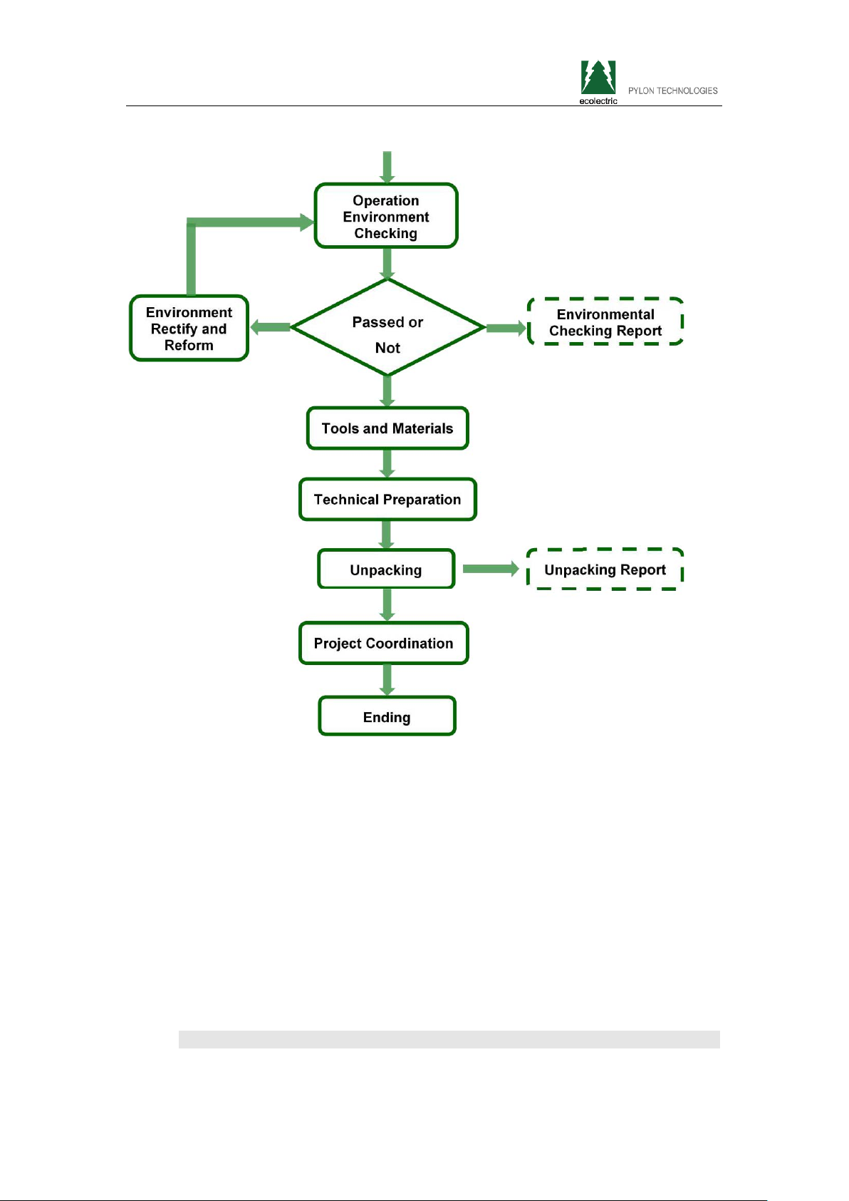
installation preparation process shown in Figure 3-1
Figure 3-1 Schematic of Installation Process:
the same time battery device must be turned
Pylon Technologies Co., Ltd. Confidential Proprietary 8
Page 15
Extra2000LithiumIronPhosphateBatteryBackupManual
3.1.1 Environmental Requirements
Ambient Temperature: -10℃~+55℃
Relative Humidity:5%〜93% RH
Altitude: Under 4000m
Working environment: No conductive dust and corrosive gas
3.1.2 Tools and Information
Hardware
Tools and instruments are shown in Table 3-1:
Pylon Technologies Co., Ltd. Confidential Proprietary 9
Page 16

Name
Extra2000LithiumIronPhosphateBatteryBackupManual
Table 3-1 Tools and Meters
Screwdriver (Slotted, Phillips)
Wrench Clip-on Ammeter
Diagonal Pliers Insulating Tape
Pliers Thermometer
Clip Pliers Antistatic Wrist Ring
Strippers Ties
Technical Information
"Project Exploration Station Report", "Extra 2000 lithium iron phosphate Standby
Power User's Manual" and "installation and inspection reports".
3.1.3 Technical Preparation
Electrical Interface Checking
Connected directly to the battery device could be user equipments, switching
power supply or other power equipments. There are two typical interface device of
power line:
Multimeter
1. DC Backup Power Interfaces
If the battery directly connects to the user device, please check:
To check the user whether the device with DC backup power interface and
whether the output voltage electrical equipment meets the requirements in
voltage range of Table 2-6.
To confirm the maximum discharge current capability of user interface to the
device DC backup power, must be greater than the maximum discharge
curr
ent products in Table 2-6; if not, the limiting function is required.
To confirm the maximum operating current by battery-powered user
equipment must be less than the maximum discharge current products
mentioned in Table 2-7.
2. Switching Power Supply
If the battery is connected to switching power supply, it must be confirmed the
positive and negative
switching power connector, and measure whether the output
voltage meets the requirements in Table 2-6; and also recognizing the maximum
Pylon Technologies Co., Ltd. Confidential Proprietary 10
Page 17

Extra2000LithiumIronPhosphateBatteryBackupManual
operating current of the battery-powered load devices must be less than the
maximum discharge current related products in Table 2-7.
Landing Checking
The collocation of landing line in engine room should be furnished ground
radiation or flat, it requiring three separate parts: DC power distribution systems
protection, power system working and lightning protection.
If the area can not provide three kinds of ground because space is limited,
the three kinds can be merging and grounding resistance must be less than 1Ω.
Security Checking
Fire-fighting equipments must be available near the equipments such as powder
fire extinguishers. For more case of requirement, it should be equipped with
automatic fire extinguishing system. No flammable, explosive and other
dangerous items placed next to battery.
3.1.4 Unpacking
When equipments arrive at the installation site, before unpacking, check
whether the box appearance is intact or not, and calculate total number
according to freight highlighted list. Avoiding sunshine and rain, installation
and disassembly must follow regulatory requirements and handli
To open box slightly to protect the object surface coating;
Reading technical documents and verifying the list firstly before open the
box, to ensure object is complete and intact according to the configuration
tables and packing slips inventory, if the internal packaging is damaged
please scrutinize and record.
3.1.5 Project Coordination
Attention of Previous Work:
ng;
Specifications of Power Cord
Power cord should meet the requirements of maximum discharge current of
each product;
Installation Space and Load-bearing
To ensure there is enough space for installation, and sufficient load-bearing
capacity for battery cabine
Pylon Technologies Co., Ltd. Confidential Proprietary 11
t and brackets.
Page 18

powered down
Extra2000LithiumIronPhosphateBatteryBackupManual
Wiring
Ensure the power cord and ground wiring is reasonable. No short circuit,
water and corrosion.
3.2 Equipment Installation
Table 3-2 Installation Steps
Step 1
Step 2
Step 3
system
Mechanical
Installation
Electrical
Installation
1. Tab Installation
2. Equipment Installation
1. Connecting
Grounding Cable.
2. Electrical Installation
3. Connect the Load
4. Communication
Interface Cascade
5. Communication
Interface Collection
6. Power Supply
3.2.1 Mechanical Installation
Before installation, disconnect the entire device's power directly contact, and
recognizing that the battery is turned off (disconnect the battery power cord and
press the Reset button), to ensure there is no electrification.
1 Tab Installation
There are tabs and mounting accessories equipment box. Before the equipment
fixed, install tabs on both sides of the device, and confirm screws are tightly
connected.
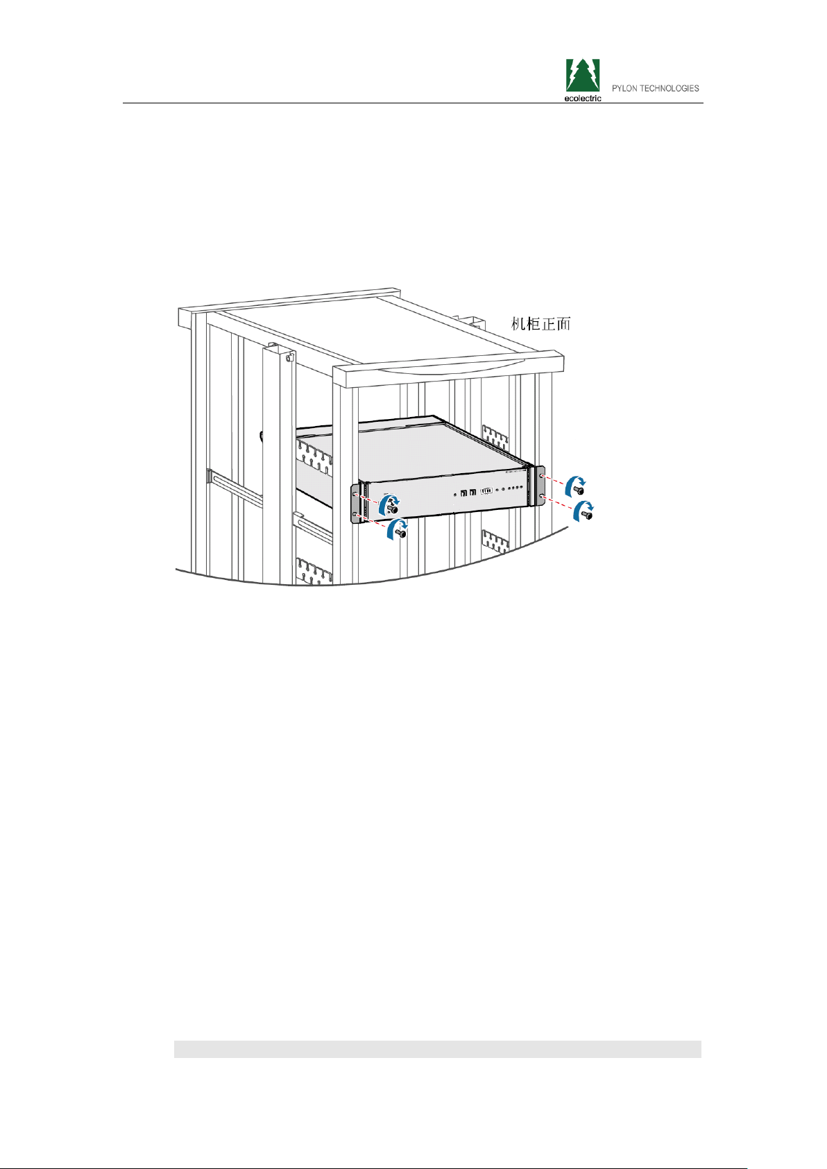
2 Equipment Installation
Extra 2000 products using 19-inch rack-mountable, it can be installed in the
Pylon Technologies Co., Ltd. Confidential Proprietary 12
Page 19
Extra2000LithiumIronPhosphateBatteryBackupManual
chassis designed with battery, and also be installed in the cabinet. Put device in
parallel on the pallet rack, push it into the cabinet to make a very tight against
between tab and the mounting bracket, tighten with screws and floating nuts, it
must be ensure that all devices are secure. The position is flexible according to the
actual for arrangements device in a cabinet.
Figure 3-2: Schematic of Device Fixed to the Cabinet
3.2.2 Electrical Installation
Before connecting power and landing, using multimeter to measure cable
continuity, short circuit, a
labels.
Measuring methods:
Cable continuity: Select buzz file of multimeter with a probe touch the ends
of the same color cable, if buzzer means cable is available.
Short circuit: Select resistance profile of multimeter, with a probe measuring
the same anode and cathode, if the resis
cable is available.
Anode and cathode: after power cord connected, the battery positive and
negative should be connected respectively positive and negative of
equipment.
Cables connection order:
nd confirmed anode and cathode, and make the cable
tance displayed infinite, means
1 Ground Cable
Pylon Technologies Co., Ltd. Confidential Proprietary 13
Page 20
Extra2000LithiumIronPhosphateBatteryBackupManual
Connect one side of the cable to the copper rafts to ground, and the other side
connect to the hole placed on right interface back of battery chassis with 4mm
line connection, make sure connections are tight and well grounded.
2 Batteries in Parallel
Please kip this step and go to Step 3 when using a single battery.
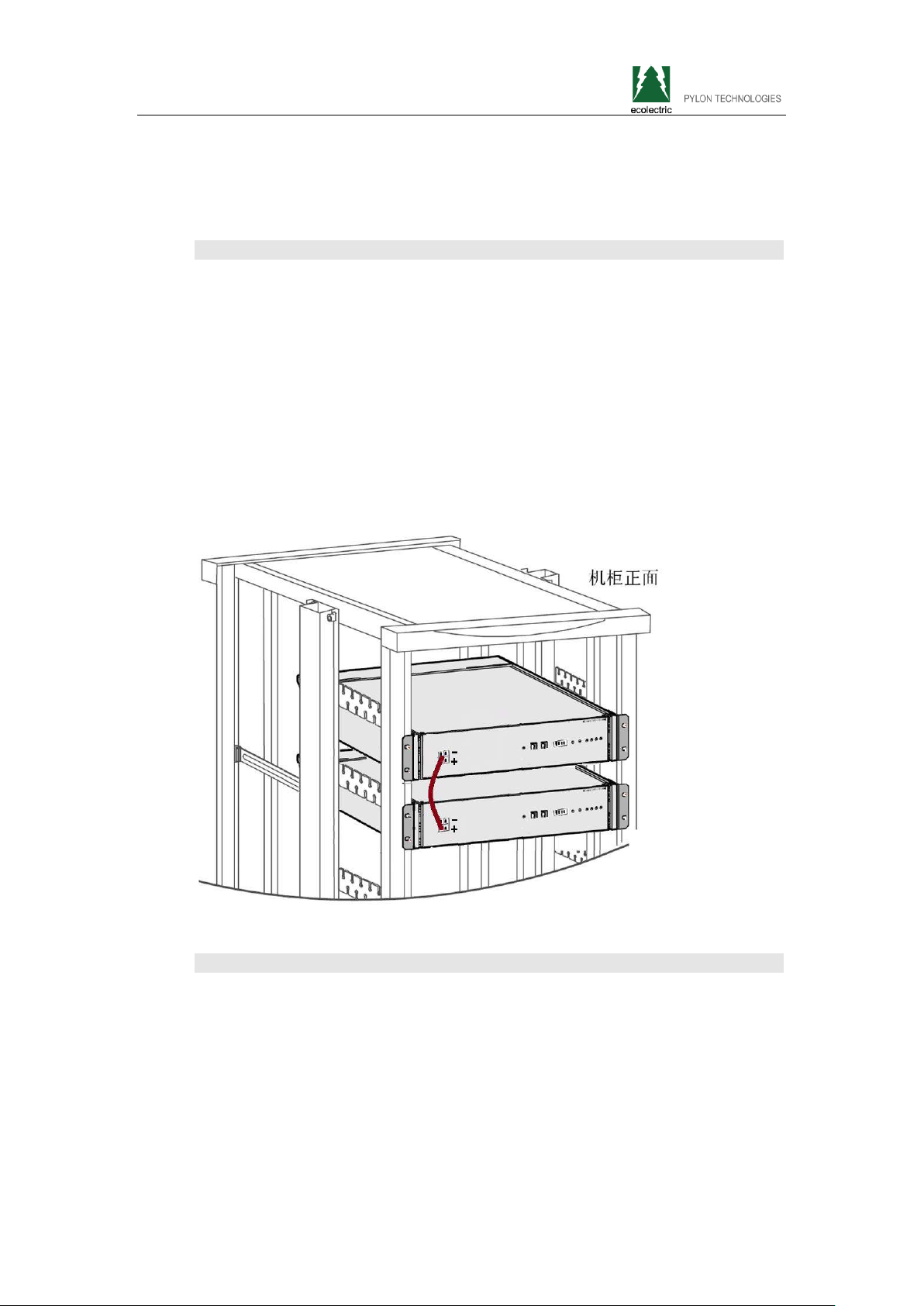
When using multiple batteries in parallel, firstly parallel each station batteries with
the power cord. Extra 2000 product has 2 power interfaces on left front panel
device, power connector from top to bottom are negative and positive. The 2
interfaces have same function, when multiple batteries in parallel, using parallel
power cable to connect each battery. After parallel, any free battery power
in
terface can connect load.
Figure 3-3 Multiple Batteries in Parallel Power Line Connection Diagram:
2
3 Load Connected
When connect load, connect the user equipment side power line interface first,
and then the battery power supply interface.
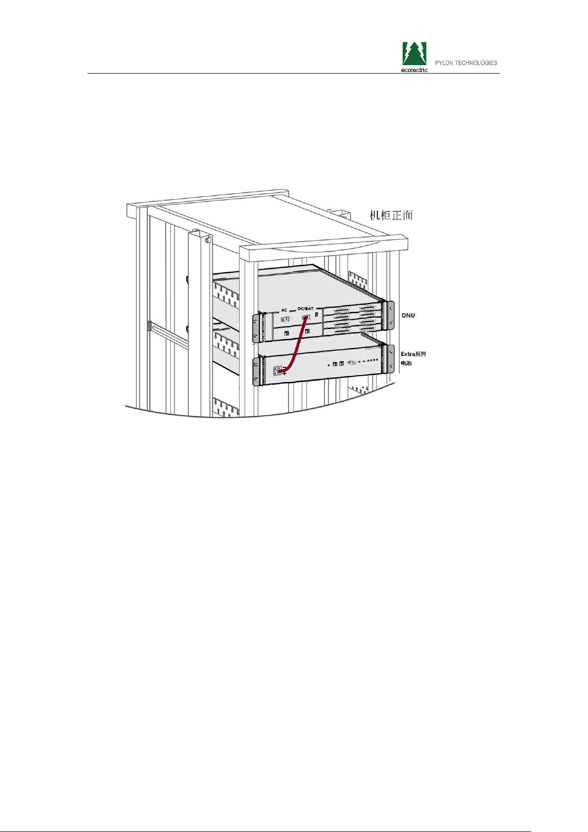
(1) Connection of battery and the load device in DC backup power interface
If the load device has a DC backup power interface, this installation can be used.
Single load equipment: the power cord directly connected to the load equipment
Pylon Technologies Co., Ltd. Confidential Proprietary 14
Page 21
Extra2000LithiumIronPhosphateBatteryBackupManual
DC backup power interface.
Multiple load equipment: use a division multiple power cords and the power cord
directly connected to each of the DC backup power load device interface.
Figure 3-4 Connection Diagram Interface between Battery and Load Equipment of
DC Backup Power
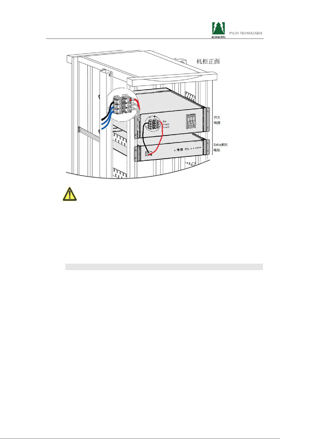
(2) Connection of the Battery and Switch Power
This installation method can be used when switching power supply to loads.
Installing the battery power cord priority access battery interface first; if switching
power supply without a battery interface, the power line can also be inserted
interface of load power supply, it should pay attention to that maximum load
ent should be greater than the maximum discharge current of relevant battery
curr
in Table 2-7.
Figure 3-5 Battery and Switch Power Connection Diagram
Pylon Technologies Co., Ltd. Confidential Proprietary 15
Page 22
Extra2000LithiumIronPhosphateBatteryBackupManual
Note:
Confirm the positive and negative of switching power supply before connecting,
the red power wire to positive and black one to negative;
Before connecting, verify the charging parameters of interface switching power
supply battery. Voltage and current should satisfy charging parameters in Table
2-6 Battery.
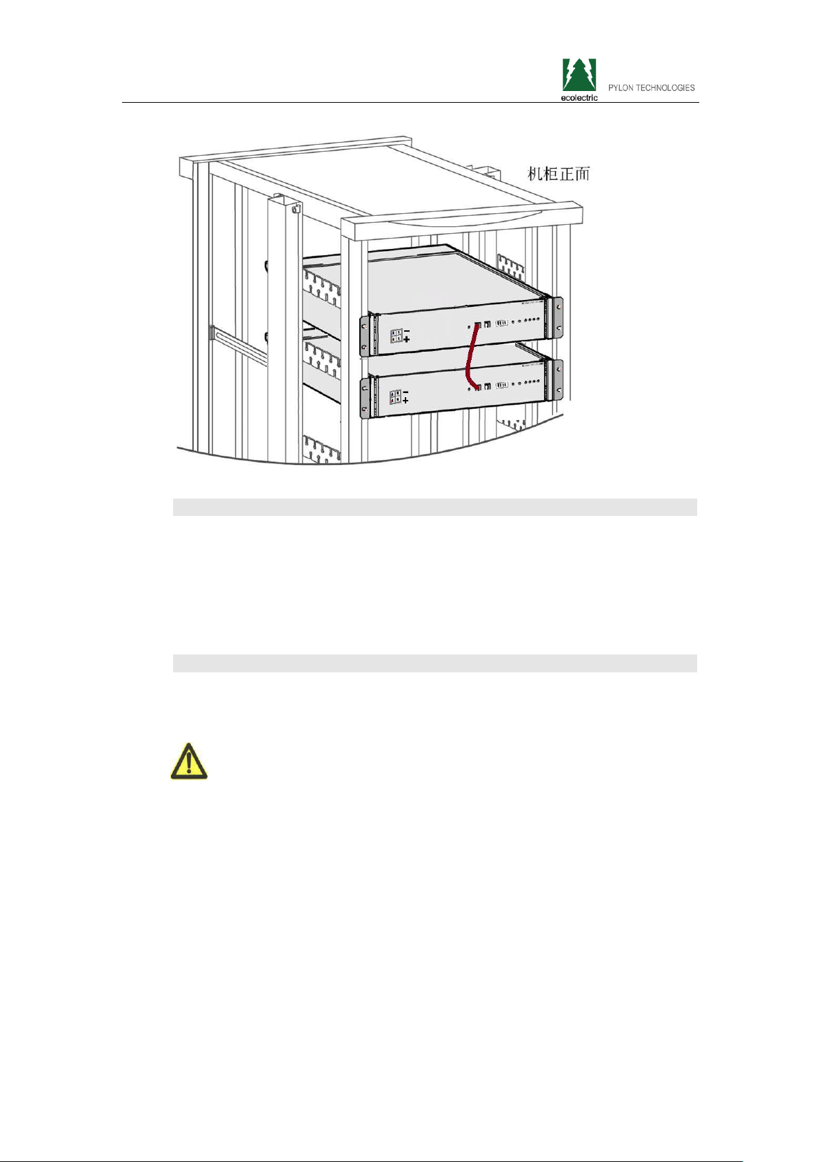
4 Cascade Communication Interface
If using a single station battery, please skip this step and proceed to step 5;
When using more than one battery,please continue with this step. (If not using the
net management, this step is not required)
To check network management information of all batteries through one battery,
please parallel each battery through RS485 interface. UTP Unshielded Twisted
Pair (line order: 568b) is used to connect two batteries of the RS485 interface.
When there are more than two, the junction box is used to parallel each interface.
After cascading, ADD switches is used for each battery sequentially assign
addres
switch" in manual "2.1.2 Equipment Front Panel".
Figure 3-6 Cascading of Multiple Batteries in Parallel Network Schematic
Pylon Technologies Co., Ltd. Confidential Proprietary 16
s code starting from 1, the ADD switches using refer to the on slip 5 "ADD
ed
Page 23
Extra2000LithiumIronPhosphateBatteryBackupManual
5 Communication Interface Connection
If using the local network, put the specially equipped RS232 communication cable
to connect the battery and computer serial RS232 interface.
If multiple network cascade battery, connect the battery RS232 interface withADD
Address is 1.
6 Powering on Device
After completing these steps, turn on power to the entire system to activate the
battery, installation completed.
Note:
After power on, if found ALM indicator in front panel red continuously over 5
seconds, disconnect the power cord to the battery and shutdown the battery,
re-check whether the device is properly connected and the positive and negative
terminals are correctly connected.
Pylon Technologies Co., Ltd. Confidential Proprietary 17
Page 24

Indication
Extra2000LithiumIronPhosphateBatteryBackupManual
4 Using, Maintenance and Troubleshooting
4.1 Alarm Description and Processing
When protection start or failure, the ALM indicator on the front panel will alarm,
through net management can query specific alarm class and take appropriate
action.
4.1.1 The Alarm and Countermeasure Influence System Output
Please follow Table 4-1 processing if output of the fault appears such as
over-voltage, charge over-current, under-voltage protection, high-temp protection
and other abnormalities.
Table 4-1 Major Alarm and Protection
Statue Alarm Category
Cell Over-voltage ALM Lighting
Charging
Discharging
Over-current ALM Lighting
high-temp ALM Lighting Stop charging
Over-current ALM Lighting
high-temp ALM Lighting Stop discharging
Low Total Voltage
Protection
Cell Voltage
Protection
Alarm
ALM Lighting Start charging
ALM Lighting Start charging
Processing
Stop charging and
find the cause
Stop charging and
find the cause
Stop charging and
find the cause
4.1.2 The Alarm and Countermeasure do not Influence System Output
If it appears the low total voltage alarm or low single cell voltage, the battery
system also generates the corresponding alarm signal. Maintenance personnel
Pylon Technologies Co., Ltd. Confidential Proprietary 18
Page 25

Category
Alarm Indication
Countermeasures
Extra2000LithiumIronPhosphateBatteryBackupManual
should inspect equipment according to prompt information, and determine the fault
type and location, and take appropriate measures to ensure the system is in the
best working condition, not to affect the system output. Phenomenon and
countermeasures are shown in Table 4-2.
Table 4-2 Secondary Alarm
Low Total VoltageAlarm ALM Flashing Stop Discharging
Low Cell VoltageAlarm ALM Flashing Stop Discharging
4.2 Common Fault Analysis and Solutions
Common fault analysis and solutions shown in table 4-3:
Table 4-3 Common Faults and Solutions
Number Fault Symptom Reason Analysis Solution
1
2
3
Related special difficulties or questions of technology, please contact Pylon
Technologies Co., Ltd.
DC power supply
time shorter
Battery cannot
be fully charged
Fire sparkle
appeared when
power up, alarm
lamp lighting
Battery capacity
reduced
Low voltage in charging
Short circuit
Change storage
battery
Adjust charging
voltage in 54V〜56.5V
Shutdown system,
check the cause and
exclusion
Pylon Technologies Co., Ltd. Confidential Proprietary 19
Page 26
WWW.PYLONTECH.COM.CN
WWW.PYLONTECH.COM.CN
With the continuous development of social requirements, business room space of operator has become tighter. This trade
brought stricter requirements for battery power backup in size and weight. Also the rapid development of economy increased
the pressure on the mains supply, and the frequent power outages result greatly reducing of lead-acid battery performance for
backup, which gives a huge procurement and maintenance costs for operators.
As a leading industry provider of lithium iron phosphate backup solutions, focus on this type of problems, Pylontech put forward
integrated high performance service of backup power protection for operators without occupying extra room space.
Small and Medium Capacity Backup Power Solutions
Some scenarios require depth coverage, the wireless base
stations are usually distributed placed, device consumption is
small, and mains failure time is short. It recommended that
Extra2000 configures one by one with each device in small
base station for problems caused by frequent power outages,
in addition, with small size and easy installation, the Extra2000
product can be flexibly installed in the narrow scenario,
especially in the tower, wall hanging and pole holding device,
at the same time, it achieves unified management and easy
maintenance through remote monitoring and management
system.
Small and Medium Capacity Backup
Power Solutions Network
Large Capacity Backup Power Solutions
In the scenario of
devices placed concentrated or very far away. When main
power fails, because of high consumption or long distance,
both require centralized backup power solutions with larger
capacity backup power systems for longer duration, and the
Extra2000 can be cascaded based on actual demand to
provide unified backup power for site to ensure continuing
operation for long duration, at the same time, through the
network management remote monitoring, achieve unified
management and easy maintenance.
gathered station or m
arginal station, the
Extra2000
Basic Parameters Extra2000
Nominal Parameters
Voltage(V) 48
Capacity(Ah) 50
Capacity(Wh) 2400
Structural Parameters
Height(mm) 132(3U)
Length(mm) 336
Width(mm) 370
Weight(Kg)
Electrical Parameters
27±0.5
Large Capacity Backup Power
Solutions Network
Operating Voltage(V) 42~54
Charge Voltage(V) 52.5~54
Maximum Discharge
Current(A)
Maximum Charge
Current(A)
Communication Parameters
Network Interface RS232
Communication Protocols YD/T 1363.3-2005
50
50
Page 27
Comprehensive advantages
Low Tot al Cost of Ownership
Long life cycles reduces cost of average life expectancy;
High energy efficiency reduces procurement costs;
Small size, it need less space for the same capacity;
Maintenance-free brings lower cost.
High Adaptability to Environment
The operation temperature range is from -10℃ to 50℃;
It is suitable for frequent outages and no memory effect;
It is designed for dustproof structure.
Intelligent Battery Management System
Each single module is designed for load distribution;
Intelligent design makes charging mode can be adjusted
according to battery charging status automatically ;
The lossless and equalization charging technology makes
charging current adjustable;
The central processor design, cooperates with multiple
monitoring modules, can fully monitoring battery information.
High Security
The battery passed drop and collision test;
The battery will be not burning or explosion in case of
acupuncture, baking and other extreme statues;
Multiple safety protection, it provides protection function in high
current, voltage, or temperature.
System Management Function
Real-time info gather and upload
Charge ending protection
Discharge ending protection
High and low temperature alarms
and protection
Charge over voltage, over current
alarms and protection
Discharge low voltage alarm and
protection
Charge over current alarm and
protection
Discharge over current alarms and
protection
Reverse alarm and protection
Short-circuit alarm and protection
Protection auto recovery
Intelligent charging and discharging
management
Lossless balanced management
Webmaster remote monitoring
Fault Logging recording
Online upgrade system
Lightning protection design
○
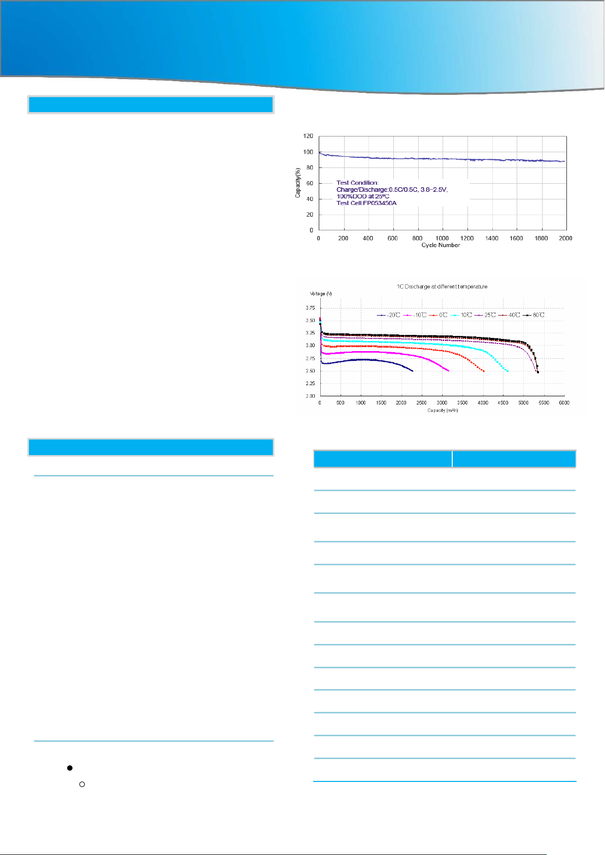
Life Cycle Curve
-20~60℃1C Rate Discharge Curve
Basic Parameters Extra2000
Life (25℃/77℉) 10 years
Life (40℃/122℉) 8 years
Life Cycles (80% DOD,
25℃/77℉)
Maintenance
Backup Duration (Average
Power 500W)
Storage Time(25℃/77℉)
Operation Temperature
Storage Temperature
Seismic Standard GR-1089
Transport Standard UN 3090
EMC Standard
Environmental Standard GB/T 2423
Free in quality guarantee
-10℃~50℃(-14℉~122℉)
-40℃~80℃(-40℉~176℉)
IEC 61000,EN 55022
>4000
period
≥5h
6 Months power off
Note: “ ” means it has this function; “-” means no such
function;
“ ” means that this function is optional.
The Authentication Level TUV,CE,CCC,TLC
For more information please contact Pylon Technologies Co., Ltd.
www.pylontech.com.cn
 Loading...