

Page 1

PLD10BT
USER MANUAL
Motorized Foldout Monitor Holder
10.1 Inch Wide Color TFT Touch Screen
Detachable Control Panel
Remote Control
Digital Video Disc Player
Control Panel USB Port and AUX Input
SD/MMC Card Slot
AM/FM-RDS Digital PLL Tuning Radio
BT Compatible
Page 2

To ensure safety while driving
and to comply with laws,
drivers should not watch video or
operate the video device while driving.
Page 3
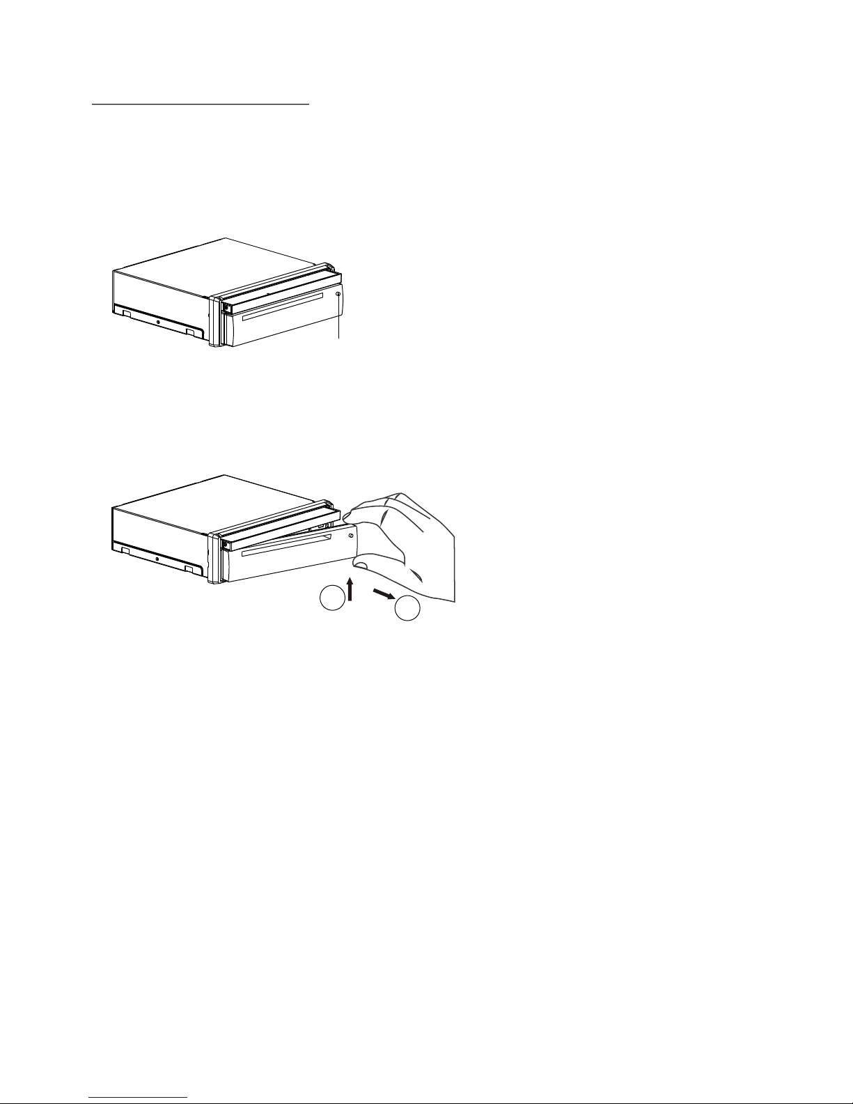
1. Remove the chassis from Slide Bracket Housing;
1) Press the REL button to release the control panel ;
2) Hold the right side of the control panel to pull it rightwards a little and then to
you for removing it ;
3) Remove the PLASTIC FRAME from the chassis (see the Installation diagram);
4) Insert the 2 KEY PLATES into the grooves at the both sides of the chassis till
they click(see the Installation diagram);
5) Pulling the two KEY PLATES to remove the chassis from the Slide Bracket
Housing ;
2. Mount the Sliding Bracket Housing in the position of car multi-media system and
bend some tabs of Sliding Bracket Housing to fix it.
3. Connecting all wires:
1) Connecting all wires according ot the wiring diagram on next page;
INSTALLATION STEPS
REL button
1
2
Page 4
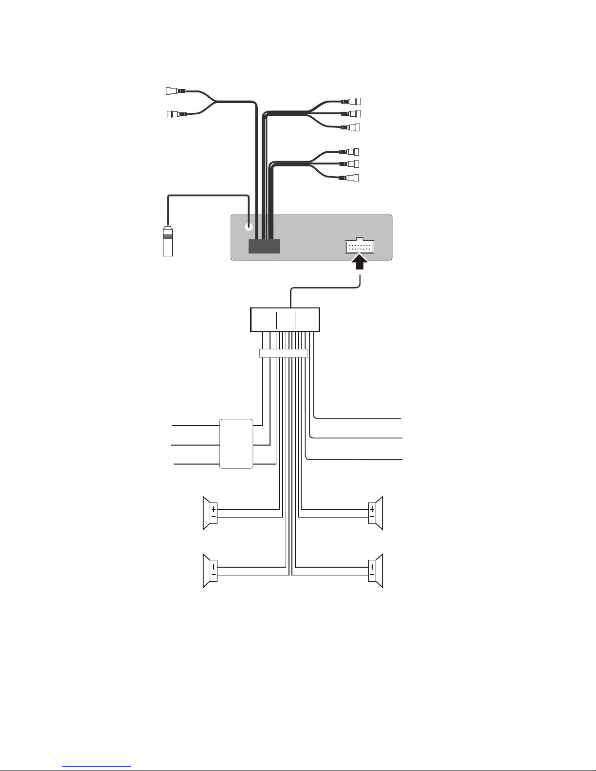
WIRING DIAGRAM
NOTE:
1. Must use 4 ohms impedance of speakers.
2. After connecting parki ng Line, video on screen of control panel
will be displayed only after
3. Before finishing wiring, do not attach control panel onto chassis.
applying parking brake.
SUBWOO FER GRE Y
VIDEO IN PUT YELLOW
RCH RED
LCH WHIT E
REAR AU DIO O UTP UT
LCH WHIT E
RCH RED
VIDEO OU TPUT YELLOW
FRON T A/V O UT PUT
REAR CAMERA INPUT YELLOW
BROWN
PINK
(B+)12V
REAR CAMERA SWITCH
(B-)PARKING B RAKE
GREY
GREY /BL AC K
FRONT
RCH SPK.
VIOL ET
VIOL ET/ BL ACK
WHIT E
WHIT E/ BLACK
GREE N
GREE N/ BLACK
REAR
LCH SPK.
AUTO ANTE NNA
BLUE
GROUND(B -)
MEMORY BACK-UP( B+)
IGNITION SWIT CH( B+)
RED
YELLOW
BLAC K
REAR
RCH SPK.
FRONT
LCH SPK.
CHOK E
BOX
RADIO ANTENNA JACK
ISO C ONNEC TOR
Page 5
Hollow
Bulge
1
2
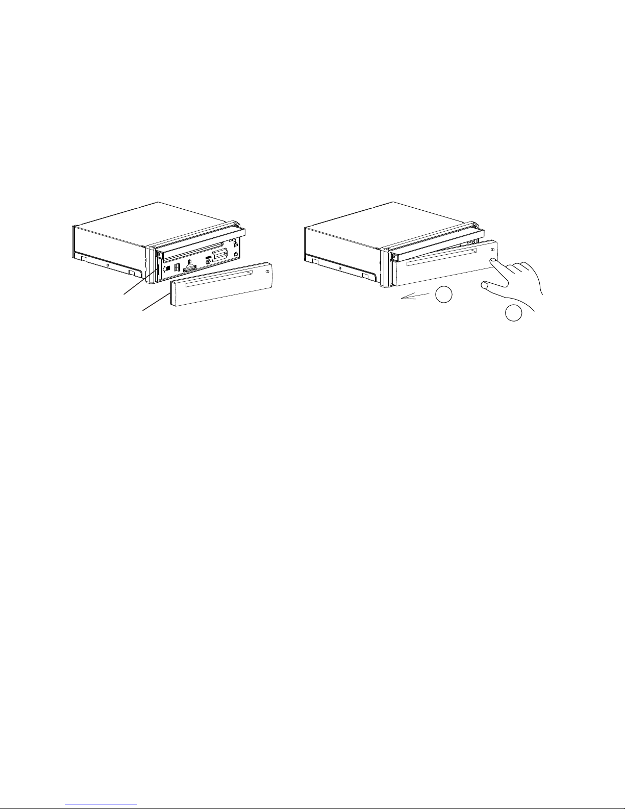
2) Attaching the control panel onto the chassis;
(1) Insert the left side of the control panel into the hollow of the chassis .
(NOTE : the “bulge” point on the control panel must be attached into the hollow
of the chassis .)
(2) Gently push the right side of the control panel till you feel a “ Click” .
3) Testing it for making sure that it can work properly .
4. Installing chassis according to the installation diagram on next page:
1) Insert the chassis of the car multi-media system into the Sliding Bracket Housing.
2) Use the metal strap to fix the rear part of chassis.
5. Installing the monitor refer to next next page.
* Uninstalling the chassis:
1) removing the monitor refer to next next page
2) Remove the metal strap from the chassis ;
3) Remove the control panel from the chassis;
4) Remove the plastic frame from the chassis;
5) Insert 2 key plates into the left and right sides of the chassis and draw the chassis
out of the sliding bracket housing.
Page 6
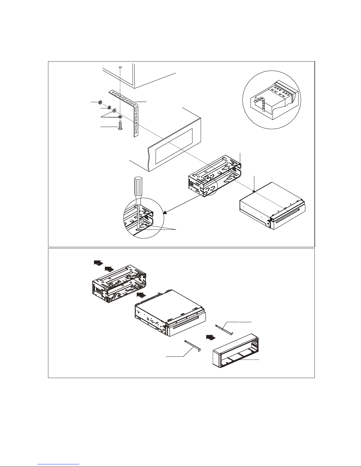
Installation Diagram
If you want to take CHASSIS out of the SLIDE BRACKET HOUSING, first remove
the PLASTIC TRIM OUT of the both sides away, then insert the two KEY PLATE into
left and right side of chassis as above illustration.
DA
SH BOAR D
METAL MOUN TIN G
STRAP
HE
X NUT
SP
RING WAS HER
PLAIN WA SHER
TAPPI NG SCR EW
CONSO LE
SL
IDE BRA CKET
HOUSI NG
HE
X BOLT
SCREW DRIVER
TABS
KEY PL ATE
KEY PL ATE
PLAST IC FRAME
Page 7
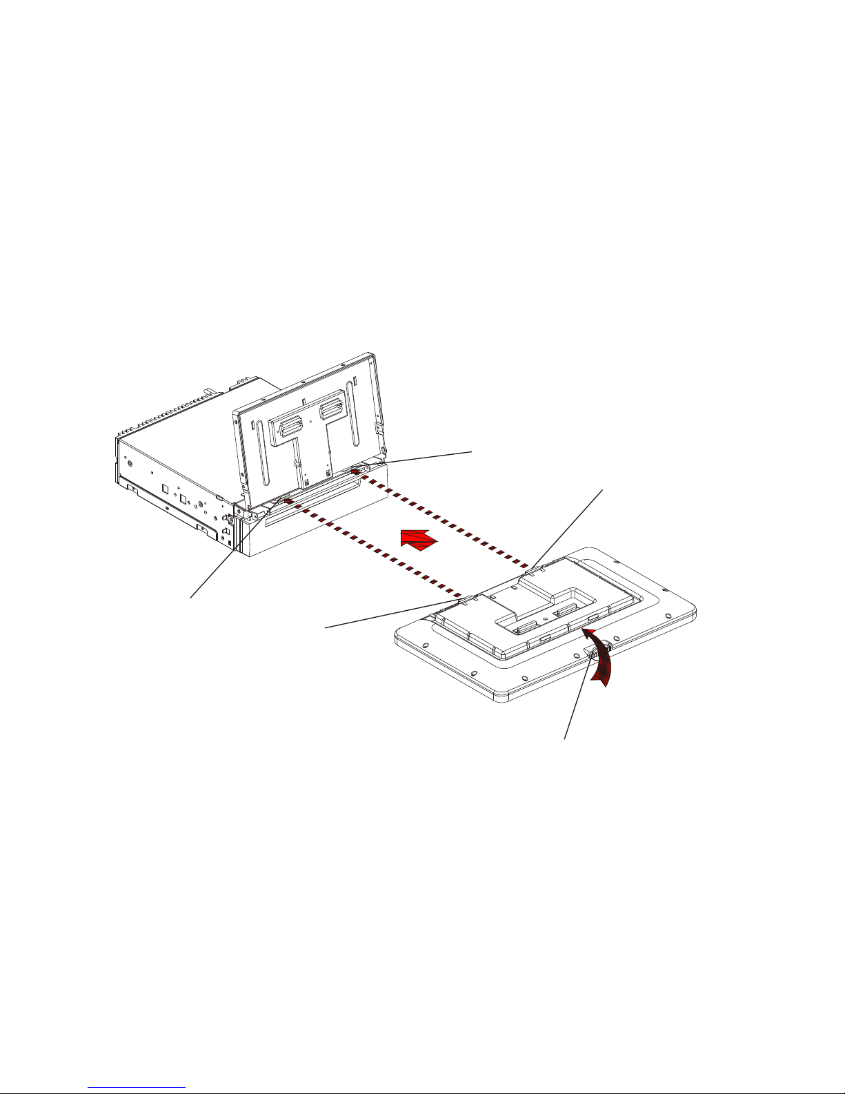
Installing the monitor.
1) Press the OPEN/MONITOR-ANGLE button to slide the monitor holder out and
stand it up.
2) Insert the 2 bulges of the monitor into the 2 hollows of the monitor holder and
flip up the monitor, then push the top middle part of the monitor to make the
monitor attach onto the monitor holder.
Removing the monitor.
1) Push the MONITOR REL to detach the monitor from the monitor holder;
2) Hold the top part of the monitor to pull away from the monitor holder and lift it
up to remove it.
Hollow
Bulge
Hollow
Bulge
MONITOR R EL
Page 8
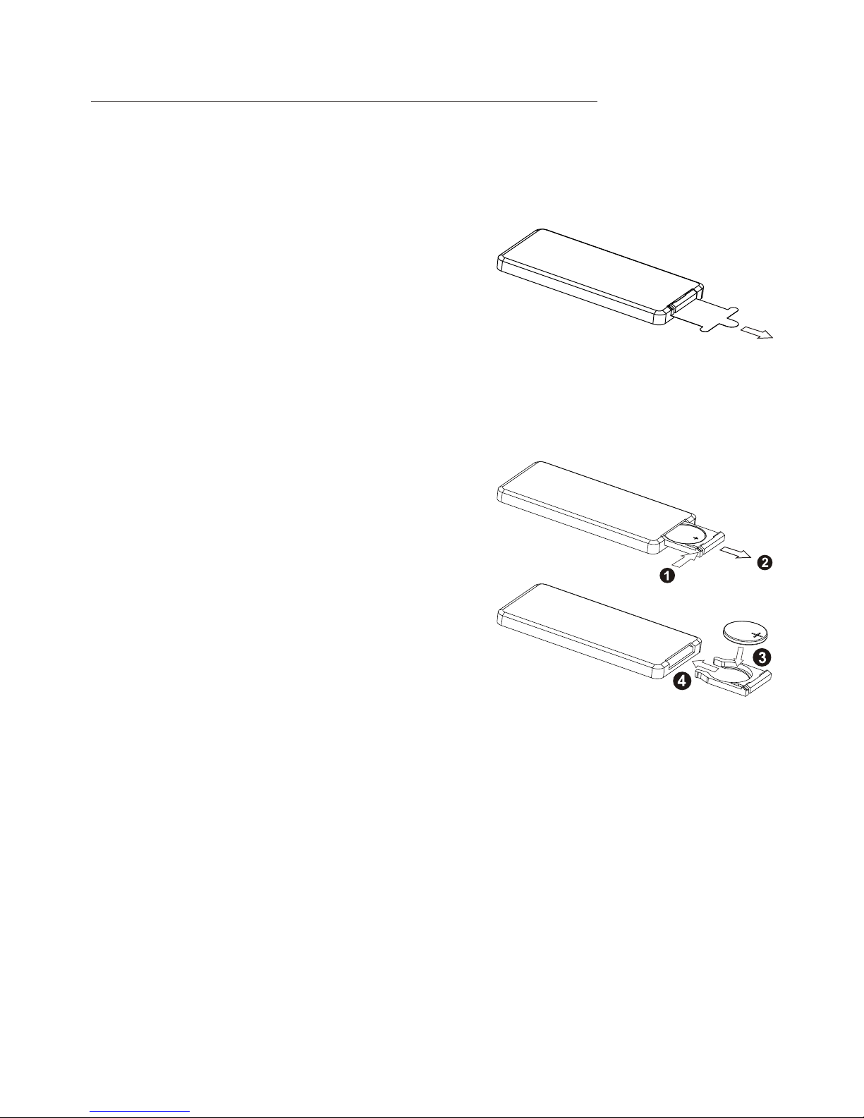
1. Removing insulating sheet
If
)
)
)
.
)
)
)
.
)
)
using remote control for the first time, you
can see an insulating sheet at the bottom
side of remote control as right.
you must remove the insulating sheet as right.
Otherwise, the remote control is disabled.
2. Replace lithium cell
If the electric energy of lithium cell is weak,
replace it.
1 Press and hold the movable block as direction
indicated by arrow 1 as right, at one time pull
cell holder out of remote control as direction
indicated by arrow 2 as right.
2 Replace the old cell by a new one with (+)
polarity side upward as right.
3 Insert the cell holder into remote control again
as right.
3 Note about using remote control
1 You should face the emitting window of remote control towards the sensor
window of the unit.
2 Operation angle for front panel: About 30 degree
3 The distance between the emitting window of remote control and the sensor
window of the unit : < 5M .
4 Warning for lithium cells of remote control
leakage may cause damage to remote control.1 Cell
2 Do not throw cells into fire, it may cause explosion.
.
3.To avoid risk of accident, keep cells out of reach of children.
GENERAL KNOWLEDGE ABOUT REMOTE CONTROL
Page 9
Co
ntrol Panel
Sl
iding Plate diagram aft er remo ving Co ntrol Panel
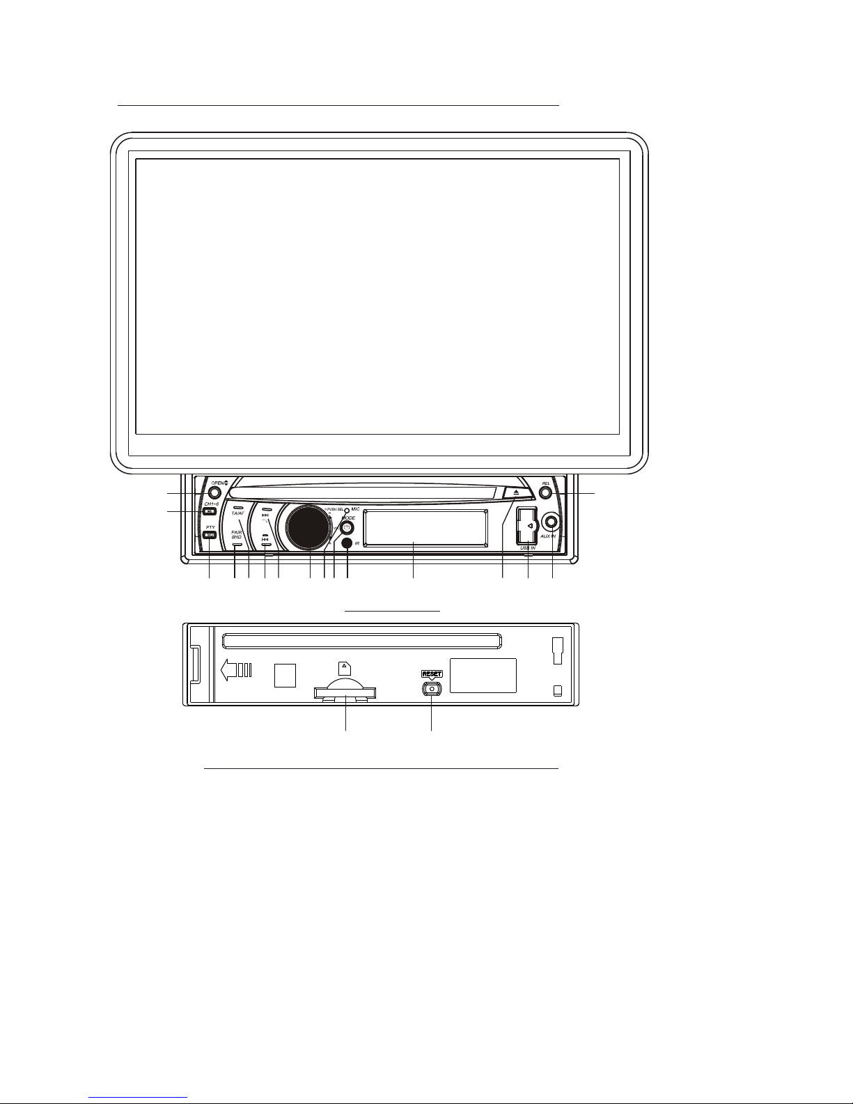
Locations and Names of Controls on Main Unit
1. AUX IN JA CK(A/V)
2. USB PORT an d COVER
3. SEL BUTTON and V OL KNOB
4. REL BUTTON
5. IR SENS OR WIN DOW
6. RESET BUTTON
7. EJECT BUTTON
8. POWER/MOD E BUTTON
9. BAND/ PAIR B UTTON
10. MUTE /PTY BUTTON
11. |<</HANG U P BUTTON
12. >|| or CH1-6 B UTTON
13. >>|/CALL BUTTON
14. SD/M MC CAR D SLOT
15. LCD SR EEN
16. OPEN /MON ITOR-ANG LE BUTTON
17. MICR OPHO NE
18. TA/AF BUT TON
6
14
2
3
4
5
7
9
1
11
10
8
12
13
17 15
16
18
Page 10
1
2
6
10
11
3
20
21
33
9
1
2
17
34
23
4
5
7
8
13
14
1
5
16
18
19
22
24
25
26
27
28
29
30
31
32
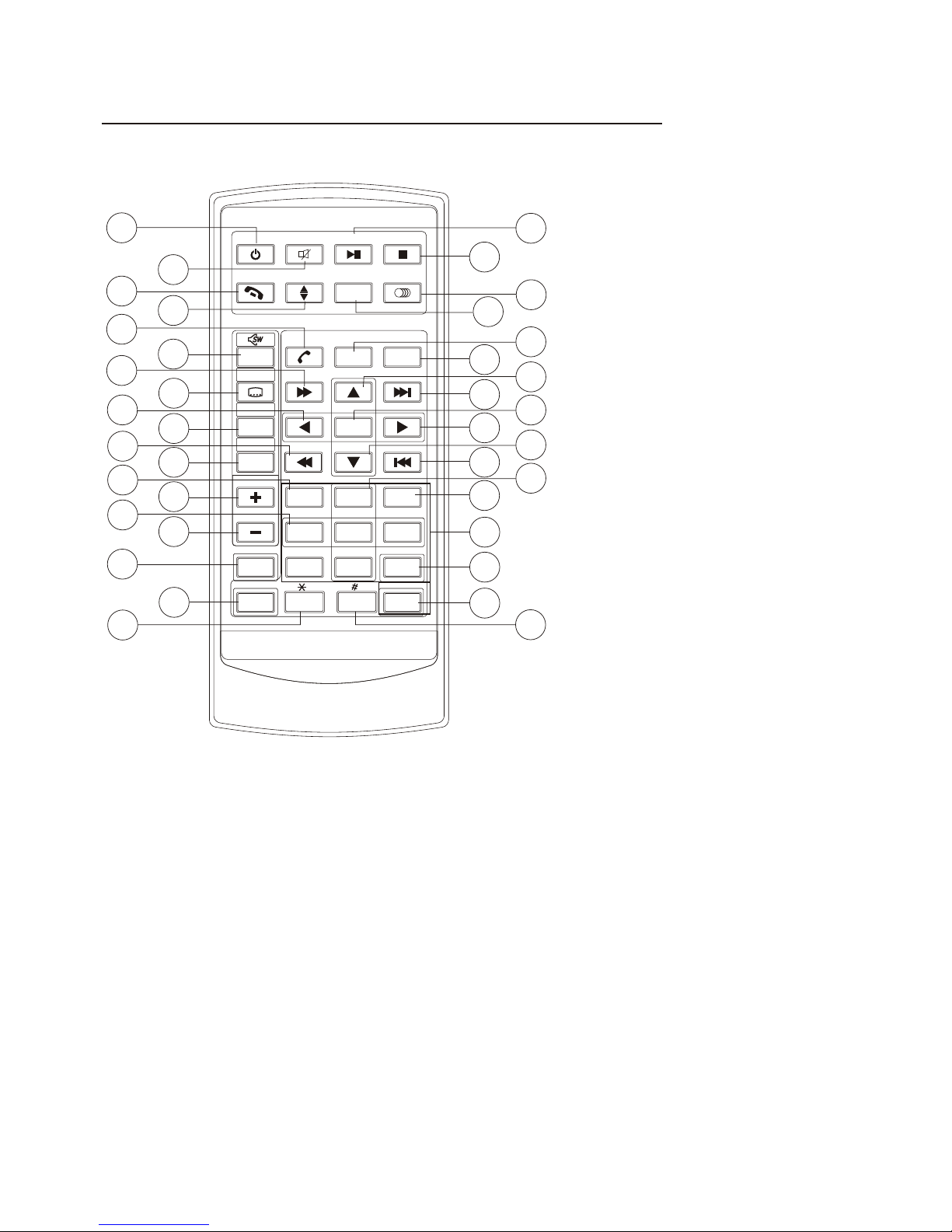
Locations and Names of Controls on Remote Control
16. VOL- BU TTON
17. SEL BUTTON
18. SETUP BUTTON
19. GOTO or * BUTTON
20. >|| BUT TON
21. STOP BUTTON
22. AUDIO or MO/ST BU TTON
23. ZOOM BU TTON
24. EQ or LOU D BUTTON
25. CLK BUTTON
26. ^ BUTTON
29. > BUTTON
30. V BUTTON
31. |<< BUT TON
32. INT BUT TON
33. NUMBER(0~9) BUTTON
34. +10 or # BUTTON
35. AF BUTTON
36. TA BUT TON
37. RPT BUTTON
27. >>| BUT TON
28. ENTER B UTTON
1. POWER/ MODE BUT TON
2. MUTE BUT TON
3. HANG UP or REDIAL BUTTO N
4. MONITOR-ANGLE BUTTON
5. CALL or PAIR BUTTON
6. MENU or SW BUTTON
7. >> BUTTON
8. SUBTIT LE or LO/D X BUTTON
9. < BUTTON
BAND or OSD
<< BUTTON
12. A/PS or TITLE/PBC BUT TON
13. TOP BUTTON
14. VOL+ BU TTON
15. RDM BUTTON
10. BUTTON
11.
35
36
37
ME
NUME NU
SE
TU P SE TU P
EN
TE REN TE R
11
22
33
44
55 66
77
88
99
00
VO
LVO L
SE LSE L
A/PSA/PS
MU TEMU TE
ST OPST OP
MO /S TMO/S T
MO
DEMODE
CL
KC LK
PL
AY /P AU SEPL AY /P AU S E
EQE
Q
BA
NDB AN D
VO
LVO L
OS
DOSD
TI
TLE /PBCTIT LE/PB C
LO
/D XL O/D X
GO
TOG OTO
+1
0+ 1 0
TOP
INT
RDM
REDI AL
PAIR
LOUD
RPT
ZO
OMZO OM
TA
AF
Page 11

Same functions in any work source mode
1. POWER b utto n and icon
In power o ff mo de, pressin g POWER butto n on remote con trol or pressing PO WER button on
contro l pane l power s on mai n unit.
In power o n mode , long pr essi ng POWE R butt on on control p anel or o n remo te control or t ouch
icon on so urce m enu pow ers off main unit.
2. VOL knob & VO L+/V OL- but tons
To adjust vol ume lev el, ro tate VOL kn ob on co ntrol p anel o r press o r hold V OL+ or VOL- but ton
on remot e cont rol.
3. SEL butto n
To swit ch between BA SS,TREBLE ,BAL ANCE, FA DE,C OLOR,BRIG HTNESS,CO NTRA ST, TINT
and VOLU ME, br iefly and rep eatedly pre ss SEL butt on.
After swi tchi ng on the desir ed mode a bove , rotate VOL knob o r press VOL+/ VOL- button s to set it.
To swit ch between BT, RE G, PI, TA, AF, LOUD, SWF, EQ, D X/LO CAL(i n radi o mode) , STER EO/
MONO(in radi o mode), TIME 1 2H/24H, CLO CK, BUZZ,EUR/US A FREQ,ANIMATION , BG and LED,
long pre ss SEL button to sw itch on BT, then br iefl y and rep eate dly pre ss SEL button.
After swi tchi ng on the desir ed mode a bove , rotate VOL knob o r press VOL+/ VOL- b utton s to set i t.
4. MUTE bu tton
To swit ch MUTE mode on o r off, press M UTE bu tton on remot e control or pr ess MUTE butt on on
contro l pane l.
5. To switc h betw een EQ modes
To sele ct a desired pr eset EQ mode fr om JAZZ, CLAS SIC, POP, ROCK and USE R, press EQ/LOUD
button o n remo te cont rol co ntinu ousl y.
6. To switch L OUD mode
To swit ch LOUD mode be tween ON and OF F, lon g press E Q/LO UD button on re mote contro l.
7. SW button
To swit ch SWF betwee n ON and OFF, lon g pres s SW button on re mote contro l.
8. CLK but ton
Press CL K butt on on remote co ntrol to disp lay clock tim e .
9. OPEN/ o r butt ons and icon
To slid e the monitor h older out and s tand it up or int o the monitor h older slot( afte r removing th e
monito r), pr ess OPEN/ but ton on c ontro l pane l or pres s butt on on remote co ntrol;
To adjust th e angle of the mo nito r, long pr ess OP EN/ button on c ontr ol pane l or but ton on
remote contr ol or touch ico n on source men u .
10. MODE b utto n and sou rce me nu
To swit ch work sourc e between RAD IO, DISC(af ter inserti ng a disc), USB (aft er inse rtin g a USB
storag e), CA RD(after in serting a car d), AUX IN and BT MUSIC , press MODE bu tton o n remot e
contro l or pre ss MODE butto n on control pa nel continu ously.
During d isc( non-C D)/U SB/card pla yback, touc h screen to pop u p Function Ic ons-board a nd then
touch th e icon i n the Functio n Icons-boa rd to enter the d isplay stat us of th e sourc e menu
before e nter ing Dis c/US B/Card mode (refer to Dis c/USB/Car d Operation ) .
During AU X play back, touch s creen to pop up A UX interfac e and then touc h icon t o enter the
displa y stat us of the sourc e menu before e ntering AUX mo de(refer to AU X operation ).
In radio, BT musi c or CD mode, touch ico n to enter the di splay statu s of the s ource m enu
before e nter ing radio,BT music or C D mode(refe r to Radio Oper ation, BT Op erat ion and D isc/
USB/Ca rd Ope ratio n).
Page 12

The sour ce menu displays as follows:
In sourc e menu, touch one icon of DISC, RA DIO, BT MUSIC , AUX, USB a nd SD Car d
to enter o ne work s ource o f DISC, R ADIO, B T MUSIC, AUX IN, USB and SD Card.
11. SETU P icon
1) SETTI NG SYST EM
In sourc e menu, touch SETUP ico n to disp lay SYS TEM pag e of SETU P menu as follows:
In the SYS TEM pag e of SETU P menu , repea tedly t ouch th e or icon to highlight one setting
item of BR IGHTN ESS, CO NTRAS T, COLOR, TINT, AN IMATION, WALLPAPER, LED and BT.
After hig hlighting a desired settin g item, t ouch th e or icon to set it.
2) SETTI NG SOUN D
In SETUP menu, t ouch SO UND ico n to disp lay SOU ND page o f SETUP menu as follows:
Sourc e Menu
Syste m page o f SETU P men u
Sound p age of S ETUP menu
BRI GHTNE SS
CONTRA ST
COLOR
15
00
BAS S
BAL ANCE
FADE
Page 13

In the SOUN D page of SETUP menu, repeatedly touch the or icon to highlight one s etting
item of TRE BLE, BASS, BALANCE, FADE, SUBWOOFER, LOUDNESS, RA DIO LOC/DX(ent ering
Source Menu in radio mode), RA DIO STEREO(ent ering So urce Menu in radio mode) and BUZZER
ON/OFF. A fter hig hlight ing a desired setting item, touch the or icon to set it.
3) SETTIN G TIME
In SETUP me nu, touch TIME icon to display TIME page of SETUP menu as fol lows:
In the TIME p age of SET UP menu, repeatedly touch the or icon to highlight one setting
item of HOU R, MINUT E and 24H/12H. After highlighting a desired s etting i tem, tou ch the or
icon to set i t.
4) SETTING R DS
In SETUP menu, touch RDS ico n to displ ay RDS page of SETUP menu as fo llows:
In the RDS pa ge of SETUP menu, repeate dly touc h the or ico n to highl ight one setting item
of REGION a nd PI SOUN D/MUTE . After hig hlighting a desired setting item, touch the or
icon to set it.
After fini shing setting, touch icon to return back to nor mal play back.
12.RESET butto n
When LCD displays wrongly or some buttons are not availa ble or sou nd is distorted, press REL
button to d etach th e control panel and remove it, then use t he sharp e nd of a poin ted object to
press RESET button on the ch assis fa ce to rese t the program to zero.
13.REL butto n
To detach contro l panel, p ress REL butt on on cont rol panel.
After deta ching control panel, hold t he right p art of the c ontrol p anel and pull it rightwards a little
and then you can remove it from chassis.
Time pag e of SETUP menu
11: 36 AM
HOUR
MINUTE
24/12H
ON
REGION
PISOUND/MUTE
Page 14

Radio Operation
1. To enter RADIO mode(MOD E button or RADIO i con)
When you use MODE bu tton or source me nu (tap ping RAD IO icon ) to enter RADIO
mode, it will disp lay radio inter face as follows :
* Some icons on radi o interface cor respond with th e butto ns on remote cont rol or control
panel as follows :
icon = MUTE button
- and + icons = VOL- and V OL+ buttons = VOL kno b
EQ icon = EQ button
: To enter source m enu.
icon : press it to pop u p BT PHO NE interface( after p airing and conn ecting a mobile
phone with BT function )
2. To switch betwee n bands ( BAND)
The BAN D icon or button ca n switch betwee n bands of FM1, FM2, FM3, AM 1 and AM2,
and the word FM1,F M2,FM 3,AM1 or AM2 will be d isplayed on scr een.
3. To search for a station ( and i cons or v and ^ or |<< an d >>| but tons)
1) Long touching o r icon or long pres sing v or ^ button on remote c ontrol or long
pressing |<< or >> | butto n on control pane l can automatic ally search dow n or up for
an available sta tion beginnin g from the curren t frequ ency.
2) Briefly touch ing or ic on or briefly pre ssing v or ^ button o n remote control or
briefly pressi ng |<< or >>| button on cont rol panel can man ually search do wn or up
for a your desired s tation beginn ing fro m the current fre quency.
4. To preset and scan a ll memory stations (AP S icon or A/PS butto n)
1) When long touch ing APS icon or long p ressing A/PS but ton on remote control , th e radio
searches from th e lowest freque ncy and checks th e signal streng th leve l until 1 cycle
search is finish ed, and t he 6 strongest st ations are pres et to cor responding pr eset number
memory bank for th e current band.
The presetting f unction can be im pleme nted in selecte d FM or AM band. (It can p resets
3x6 stations for F M and 2x6 stations for AM in al l)
2) When briefly to uching APS icon or b riefly pressi ng A/PS bu tton, t he radio scans fo r each
preset station i n FM or AM band from NO.1 bank, e ach preset stat ion broadcas ts for 5
seconds. After fi nishing a circl e of scanning, it w ill res ume broa dcast ing the station i n NO.
1 bank.
NOTE: In FM band, FM 1,FM2 a nd FM3 are preset a nd scaned as one ba nd at a time;
In AM band, AM1 and AM2 are preset a nd scan ed as one ba nd at a tim e.
88. 5088.5 0
90. 0090.0 0
98. 0098.0 0
106 .0 0106 .0 0
103 .0 0103 .0 0
80. 5080.5 0
FM1FM1
87.5087.50
MHZM HZ
Page 15

5. To preset and listen to a memory station(1~6 icons or 1~6 buttons or CH1-6 button )
1) Long touching one of 6 number(1~6) icons or long pressing one of 6 number(1~6)
buttons can preset the current broadcasting station of the current band in the number
memory bank; .
2) Briefly touching one of 6 number(1~6) icons or briefly pressing one of 6 number(1~6)
buttons can listen to the memory station in the current band preset in the number
memory bank.
* CH1-6 button:
1)To preset a station in a memory bank with CH1-6 button, first select a desired
band; then press CH1-6 button to select a desired memory bank; and then search
for a desired station; finally long press CH1-6 button to store the station in the
memory bank.
2)To listen to a preset station with CH1-6 button, first switch on a desired band, then
continuously press CH1-6 button highlight and listen to it.
6. To switch on between stereo and mono mode (MO/ST button)
Press MO/ST button on remote control to select STEREO or MONO mode for FM band.
When the STEREO mode is activated, it can get better audio effect; when the
MONO mode is activated, it can get clearer audio signal.
7. To switch on between local and distance mode (LO/DX button)
Press LO/DX button to turn LOC on to tune for local stations with weak interference;
Press LO/DX button to turn DX on to tune for distance stations with stronger signal.
8. To search for a RDS station that is broadcasting a typed program (PTY)
Continuously touching PTY icon on touch screen or continuously long pressing PTY
button on control panel switches between the program types such as: NEWS ...and
so on.
After selecting a desired program type, no operation for a while, it displays PTY
SEEK and automatically searches for a station that is broadcasting the selected
type of program.
If the station that is broadcasting the selected type of program does not exist, it will
display NO PTY and return back to the previous normal station.
9. To automatically alternate a stronger signal of frequency for the current RDS station(AF)
During broadcasting a typed program of a RDS station, use the AF icon in the RADIO
interface or SEL and VOL buttons to set AF mode on or long press AF button on control
panel or AF button on remote control to switch on AF mode, then AF icon flashes on
screen.
After switching on AF mode, the radio checks the signal strength of AF(alternate
frequency) all the time. Whenever a new AF is stronger than the current frequency,
Page 16

It switches over to the AF for a short time, and the AF icon is light on screen(not
flash).
* In FM mode, when switching on AF mode, the radio auto searches for or preset
only those RDS stations.
* In FM mode, when switching on AF and TA modes, the radio auto searches for
only those RDS stations broadcasting traffic announcement.
10. REGION mode
use the RDS page of the SETUP MENU or the SEL and VOL buttons to set
REGION mode on or off.
In REGION on mode, when switching on AF mode, the radio can’t switch over to
those AF stations which have a different regional program content.
In REGION off mode, when switching on AF mode, the radio can switch over to
those AF stations which have a different regional program content.
11. PI mode
use the RDS page of the SETUP MENU or the SEL and VOL buttons to set PI
SOUND or PI MUTE mode.
In PI SOUND mode, when switching on AF mode, if a car cruises that critical area
back and forth, an oscillation phenomenon can be occurred, because the different
PI code can be receive from a same AF. when the different PI sound (DIP) is heard
once in a while, the different PI sound will be heard for less than 1 second.
In PI MUTE mode, when switching on AF mode and under above same situation,
a mute sound will be heard for less than 1 second.
12. To automatically search for traffic announcements (TA)
In any mode, use the TA icon or SEL and VOL buttons to set TA mode on or press TA
button on control panel or long press TA button on remote control to switch on TA mode,
then TA: ON will display on screen for a while and begin to search for those RDS radio
stations transmitting traffic announcement.
When an RDS radio station transmits traffic announcement and is received by the
radio, temporarily switch the current work source to an RDS radio station broad casting traffic announcement, and TRAFFIC will be displayed on screen.
When the traffic announcement is over, it will return back to previous work source.
Page 17

BT Operation
1. Pairing and Connecting
Prior to using the BT device named BC_HF_V01 as a handfree system for a BT-
enabled mobile phone for the first time, you must as follows:
* Prior to pairing and connecting, when displaying No Video interface of radio, CD,
AUX IN or BT music, the logo BT flashes in the touch screen.
* During using the BT device named BC_HF_V01 as a handfree system for a BT enabled mobile phone, place the BT-enabled mobile phone in 3 meters from the
Car A/V System;
1) Long press PAIR button on remote control or long press PAIR button on control
panel to flash the logo of the BT with blue frame;
2).Switch on the BT mode of your mobile phone; then s BT
device and enter it; device car
BC_HF_V01 , select it and enter it; then it will show an interface
that asks you to input a password, input 8888 and enter it; then i
with the BT device BC_HF_V01 of the car A/V system, Confirm it, then
the frame of the BT logo will be filled by blue color and they are light all the time.
* finishing pairing and ing
or the mobile phone
plays music
2. BT PHONE
1) Make a call
(1) Dial with mobile phone directly;
(2)Dial with the controls on BT PHONE interface or on remote control or on control
panel
a. Long press button on remote control or touch icon to pop up BT PHONE
interface as follows:
pair and connect them
elect the item to find a
When it finds the BT of the A/V system, the name
will be displayed
t will pair and
connect
When connect , the audio of the mobile phone transfers
to the car audio system whenever a call is made or received
.
: Same as MUTE button.
- & + : Same as VOL+ and VOL- or
VOL knob.
Page 18

USER SWFUSER SWF
BT
MUSI C
BT
MUSI C
b. Use the number icons or buttons to input your desired phone number;
* When inputting a wrong digit, use icon or < button to delete it.
c. After finishing inputting, touch icon or press button on control panel or press
button on remote control to dial out.
2) Redial last dialed phone number
Touch icon or long press button on remote control to dial out the last dialed
phone number.
3) Answer a call
During ringing, the incoming telephone number displays in the the BT PHONE
interface. If you want to receive it, touch icon or press button on control
panel or press button on remote control; if you want to reject it, touch icon
or press button on control panel or press button on remote control.
4) End phone talking
When you want to end phone talking, touch icon or use or button.
5) Switch audio between car A/V system and mobile phone
During phone BT handfree system of the car A/V system, if you
want to change the phone audio to your mobile phone, touch icon or press
button on control panel or press button on remote control.
During phone talking using the mobile phone, if you want to change the phone
audio to the the car A/V system again, use or button.(only for some mobile
phone)
6) phone
During phone + and - icon or
; use icon or MUTE button to mute sound
* * / # icons and buttons
they perform as * / # buttons on mobile phone.
3 BT MUSIC
1 Touching BT MUSIC on source menu or pressing MODE button can pop up BT
MUSIC interface as follows:
talking using the
Adjust volume level during talking
talking, use VOL knob or VOL+ and VOL-
buttons to adjust volume level .
.
)
USER SWFUSER SWF
BT
MUSI C
BT
MUSI C
Page 19

- and + icons = VOL- and VOL+ buttons = VOL knob
icon = MUTE button
EQ icon = short pressing EQ/LOUD button
icon : Popping up BT PHONE interface(after pairing and connecting a mobile
phone with BT function).
icon = button
icon = button
and icons = and button
icon: To enter source menu.
TA ico n : To switch TA mode o n or off.
AF icon : To switch AF mode on or off.
) using your mobile phone with BT function to audio/video if it
with the audio of the mobile
phone will change into .
The BT device of the car A/V system support A2DP, if your mobile phone with BT
function support A2DP, the car A/V system can output stereo audio from your
mobile phone.
) T the car A/V system so these icons on the BT
MUSIC interface except BT Music and their buttons on control
panel or on remote control are available for audio/video playback of your mobile
phone during playback. But n for / icon
and / buttons, and the function of resume playback after pausing or stopping
is available only for some mobile phone
to display BT, to BT
2 When play , is paired
and connected the BT device of the car A/V system,
the car A/V system
3 he BT device of supports AVRCP,
corresponding
o fast forward/backward functions
.
* If you don’t want to use the BT function of the car A/V system , long press SEL
button then use VOL knob or VOL+ and VOL- buttons switch
off .
Page 20

Disc/USB/Card Operation
1. Loading or unloading a disc, USB or card
1.1 Loading a disc, USB or card
To play files in a disc, insert a disc with label surface up into disc slot. it will
automatically play.
* CAUTION OF USING DISC
1) Handle a disc by its edge, do not touch the surface of play side.
2) Before inserting disc, wipe the disc outwards from the disc
center with a clean, soft, dry, lint-free cloth. Do not use solvents
/thinner such as petrol/benzine, cleaner.
3) After taking a disc out of disc slot, put the disc inside disc case to
keep it clean.
4) Do not stick paper or tape on the disc surface of play side. If
there is glue (or analog) on the disc surface, must wipe it up
before using.
To play files in a USB, firstly open USB port cover, then insert USB storage into
USB port, and then it will play files in the USB automatically.
To play files in a card, firstly press REL button to detach control panel, then hold
the right part of the control panel and pull rightwards a little and to you to remove
it, and then insert the card with label side upward and contact end frontward into
card slot as the following fig., and then attach control panel onto chassis again,
by now it will play files in the card automatically .
Label
surface up
Label side
facing upward
Press in till heard a “CLICK”
Page 21

1.2 Unloading a disc, USB or card
To unload the disc in disc slot, use STOP button to stop playback and then press
button on control panel or touch icon on source menu to eject disc, then
remove it.
* During MP3/WMA playback, the information of file, folder, title, artist and album
will be scrolling on LCD display. As long as the current playing MP3/WMA music
contains relevant ID3 tag information in version 1.0/2.0 format, the 3 items
underlined above will be scrolling on LCD display; otherwise, they will not.
* There is ESP function for all formats of discs.
2. Popping up Function Icons-board
2.1 Function Icons-board of Digital Video/VCD/MPEG4/Image/MP3/WMA
During Digital Video/VCD/MPEG4/Image playback, tapping any place on touch
screen can pop up Function Icons-board 1 as next page, then tap icon to pop
up Function Icons-board 2 as next page.
During MP3/WMA playback, tapping any place except folder area, track area and
MP3/WMA&Image&MPEG4 icons can pop up Function Icons-board 1 same as one
of Digital Video/VCD/MPEG4/Image, then tap icon to pop up Function Icons board 2 same as one of Digital Video/VCD/MPEG4/Image.
To pull away the USB storage, use STOP button to stop playback, then you can
remove the USB storage.
To unload the card in card slot, use STOP button to stop playback, then press
REL button to detach control panel and then hold the right part of the control panel
and pull rightwards a little and then to you to remove it, and then you can push the
card for release it and then pull it out of card slot.
WM AWM A
Mp 3Mp3
[M P 3 ][M P 3 ]
IT LE / S O NG : TR AC K 03 / IT LE / S O NG : TR AC K 03 /
00 1001
00 2002
00 3003
00 4004
00 5005
00 6006
00 7007
00 8008
00 7007
00 1001
00 2002
00 3003
Folder area Track area
MP3/WMA icon Ima ge ico n M PEG4 icon
Remove the memory card Press in till heard a “CLICK”
Page 22

Function Icons-boa rd 1 Function Icons-boa rd 2
The Function Icons-boards display as follows:
* Some icons on the Function Icons-boards descript as follows:
: Same as MUTE button.
: Same as VOL- button or rotating
VOL knob with anti-clock wise.
: Same as VOL+ button or rotating
VOL knob with clock wise.
: Poping up source Menu.
: Poping up Function Icons-board 2.
TA icon : To switch TA mode on or off.
AF icon : To switch AF mode on or off.
2.2 CD interface
During CD playback, the CD interface displays as follows:
* Some icons on the CD interface descript as follows:
: Same as EQ button.
CLK : Same as CLK button.
LOUD: Same as long pressing EQ button.
SWF : Same as SW button.
: Poping up Function Icons-board 1.
: Poping up BT PHONE interface
(after pairing and connecting a
mobile phone with BT function).
: Redialing the last phone number.
TA icon : To switch TA mode on or off.
AF icon : To switch AF mode on or off.
icon = MUTE button
- and + icons = VOL- and VOL+ buttons= VOL knob
EQ icon = EQ button
icon : press it to pop up BT PHONE interface(after pairing and connecting
a mobile phone with BT function)
icon: To enter source menu.
Page 23

3. Function of controls on the touch screen/main unit/remote control
1. icon or button
During playback, use it to pause playback; in pause mode, use it to resume play back.
2. icon or button
During Digital Video/VCD/CD/MP3/WMA playback, tapping or pressing it pre-stop
or pause playback; in pre-stop or pause mode, use icon or button to resume
playback.
During playback, tapping or pressing it twice to fully stop playback; in fully stop
mode, use icon or button to start playback from the beginning of the media.
During MPEG4/image playback, use icon or button to display root menu as
follows:
During MP3/WMA playback, the root menu above displays all the time.
/chapter
* Tapping folder icon, track icon or kind icon can execute the operation above.
3. / icons or buttons
During playback, continuously tapping or icon or continuously pressing
or button on remote control or continuously and long pressing or button
When displaying root menu, use < or > button to highlight the current chapter/
track, the current folder or the kind icons.
* If there are no track for a kind icon, you can’t highlight the kind icon.
When highlighting a kind icon, press ENTER button to enter it.
When highlighting the current folder, use v or ^ button to highlight other folders
and then press ENTER button to enter it.
When highlighting the current track, use v or ^button to highlight other tracks and
then press ENTER button to play it.
* For image, after highlighting a track, press ENTER button to display only the high lighted track; press >|| button to display all tracks step by step from the highlighted
track.
WM AWM A
Mp 3Mp 3
[M P 3 ][ M P 3 ]
IT LE / S ON G : TR AC K 03 / IT LE / S ON G : TR AC K 03 /
00 100 1
00 200 2
00 300 3
00 400 4
00 500 5
00 600 6
00 700 7
00 800 8
00 700 7
00 100 1
00 200 2
00 300 3
Folder area Track area
MP3/WMA icon Image ic on MPEG4 icon
Page 24

on control panel can fast backwards or forwards at the following multiple of normal
speed: x2, x4, x8, x20, x1.
During fast playback, use icon or button to resume normal playback.
For image files, no this function.
4. / icons or / buttons
During playback, use one of them to play previous or next chapter/track.
During playback, long pressing or button on control panel can fast
backward or forward at the following multiple of normal speed: x2, x4, x8, x20, x1.
5. Number buttons
During Digital Video/VCD(PBC OFF)/MPEG4/Image/CD/MP3/WMA playback,
use number buttons to input chapter/track SN. , then it will play or display it.
digit in s place digit
in
6. MENU icon or button
During Digital Video playback, use MENU icon or button to display the current
chapter list, then use direction buttons to select your desired chapter and then
press ENTER button to play it.
For VCD, MENU icon or button is disabled, track list is displayed on the monitor
screen by pressing TITLE/PBC button or tapping TITLE/PBC icon.
a
i
7. TITLE/PBC icon or button
During Digital Video playback, use TITLE/PBC icon or button to display title list;
then use direction buttons to select your desired title and then press ENTER button
to open the chapter list of the title; then use direction buttons to select your desired
chapter and then press ENTER button to play.
* You can also tap a desired title and then chapter to play.
During VCD playback, use TITLE/PBC icon or button to switch PBC mode on
or off. When PBC mode is switched on, it will play from the beginning of media till
it displays a track list. When a track list is displayed, use the number buttons to
select your desired track to play.
For CD, the TITLE/PBC icon and button are disabled.
To input a chapter/track with an SN that is equal to or bigger than 10, use the +10
button to input the ten and then use 0-9 button to input the
units order.
I.e. +10 ~ 1 = 11 (number 11 chapter/track will be displayed/played.)
During VCD playback, when it is in PBC ON mode, the number buttons are disabled.
For MPEG4/image, MENU icon nd button are disabled, root menu is displayed
on the monitor screen by pressing button or tapping icon.
For MP3/WMA, MENU con and button are disabled, root menu displays on
the monitor screen all the time. Root menu of MP3/WMA is same as the one of
MPEG4/image.
For CD, MENU icon or button is disabled.
For MP3/WMA/MPEG4/image, the TITLE/PBC icon and button are disabled.
Page 25

8. icon and GOTO button
For Digital Video/MPEG4/VCD/image/MP3/WMA, you can use , , ,number
and icons or GOTO, <, >, number and ENTER buttons to select a chapter
/track or from a playback time point to play.
During playback, tap icon or press GOTO button to display changeable
playback information bar as follows:
Digital Video:
MPEG4:
VCD:
Image:
MP3/WMA:
* During playback, tapping icon can also display the Goto Function icons-board
as follows:
When displaying the changeable playback information bar, use / icon or
< or > button to highlight title SN.(only for Digital Video) , chapter/track SN. or
elapsed time of current chapter/track(disabled for image).
When highlighting title SN. or chapter/track SN. , use number icons or buttons to
input desired SN. of title or chapter/track, then use icon or ENTER button to
play the selected chapter/track.
When highlighting elapsed time of current chapter/track(disabled for image), use
number icons or buttons to input desired playback time point for the playback time
of the whole media for Digital Video/VCD and of the current chapter/track for
MPEG4/MP3/WMA, then use icon or ENTER button to play from the play back time point.
9. icon or ZOOM button
During Digital Video/VCD/MPEG4/image playback, use icon or ZOOM button
to switch zoom mode between ZOOM 2, ZOOM 3, ZOOM 4, ZOOM ½, ZOOM 1/3,
ZOOM 1/4 and ZOOM OFF.
When zooming in video/image, use direction buttons to move video/image
upwards, downwards, rightwards or leftwards.
For CD, GOTO button is disabled.
When not zooming in image, direction buttons can switch on 4 fixed rotated
angles between >=90 deg cw, <=90 deg ccw, ^=UP-DOWN and v=LEFT-RIGHT.
Page 26

icon and are
For CD, the ZOOM button is disabled.
10. OSD icon or button
During Digital Video /MPEG4/Image/MP3/WMA playback, use OSD icon or
button to display playback information bar as bellows:
Digita l Vid eo:
MPEG4:
VCD:
Image:
MP3/WMA:
11. icon or REPEAT button
During Digital Video playback, touch icon or long press RPT button to switch
repeat mode between REP CHAPTER, REP TITLE, REP ALL and REP OFF.
touch icon or long press to
E 1
For MP3/WMA, ZOOM button disabled.
/VCD
For CD , OSD button is disabled.
During VCD(PBC OFF)/CD playback, RPT button
switch repeat mode between R P , REP ALL or REP OFF.
Page 27

During MP3/WMA/MPEG4/image playback, touch icon or long press RPT button
to switch repeat mode between REP1,REP FOLDER(or DIR),REP ALL or REP OFF.
During VCD(PBC ON) playback, icon and RPT button are disabled.
2
For MPEG4/image/VCD(PBC ON) playback, RDM button disabled.
14
During VCD playback, use button to switch audio channels between
MONO L, MONO R, MIX MONO and STEREO.
For MPEG4/MP3/WMA image, button disabled.
For VCD/MP3/WMA/MPEG4/image, button disabled.
1 . icon or RDM button
During Digital Video/VCD(PBC OFF)/CD/MP3/WMA playback, tapping icon or
long pressing RDM button switches random mode on or off.
icon and are
13. icon or INT button
During VCD/CD playback, tapping icon or long pressing INT button switches
intro mode on or off.
For Digital Video/MP3/WMA/MPEG4/image, icon and INT button are disabled.
. icon or button
During Digital Video playback, use icon or button to switch between audio tracks
(depending on the current playing media).
/CD icon or
/ icon and are
15. icon or button
During Digital Video playback, use icon or button to switch subtitle languages
on or off(depending on the current playing media).
icon and are
For CD, the button is disabled.
Page 28

16. icon or SETUP button
Use icon or SETUP button to enter Media Setup Menu for setting up all media
parameter values.
Use icon or SETUP button to display Media Setup Menu(the default page is
SYSTEM SETUP);
Media Setup Menu has 4 pages in all. When highlighting a page, tap the aim page
icon or press > or < button to highlight another page;
After selecting a page, tapping the aim item icon or press ^ or v button to highlight
a setup item in the selected page;
After selecting a setup item, tapping the aim value; or press > button to enter the
setup item, then press v or ^ button to select a desired value, finally press ENTER
button to confirm it.
After finishing setting, tapping EXIT icon or press SETUP button to exit Media
Setup Menu to resume normal playback.
1) SYSTEM SETUP
TV SYSTEM
This setup item is for setting up video system in NTSC, PAL or AUTO .
If you set a non-matched video system for playing a video, the playing video will
display white-black or flash.
SCREEN SAVER
This setup item is for switching screen saver on or off.
TV TYPE
This setup item is for setting up video display size.
Description of the 4 pages:
TV S YSTEM
SC R E E N S AV E R
TV T Y P E
PAS S WORD
RAT I N G
DE FAU LT
SYST E M S ETU P
E X I T
Page 29

(1) 4:3 PS: Choose this item when connecting a monitor with 4:3 screen. When
playing video with 16:9 size, the left and right part of video will be cut out, and
video will display in full screen.
(2) 4:3 LB: Choose this item when connecting a monitor with 4:3 screen. When
playing video with 16:9 size, the top and bottom part of the monitor screen will
be turned into a black square .
(3) 16:9: Choose this item when connecting a monitor with 16:9 wide screen.
PASSWORD
This setup item is for locking or unlocking parental control. The default mode
is locked. The default unlocking password is 0000.
To lock or unlock parental control:
(1) Highlight PASSWORD item and then press > or ENTER button to enter it;
(2) Input password 0000;
(3) Press ENTER button to confirm, then it will unlock or lock parental control.
* e of the PASSWORD
RATING
This setup item is for setting a new rating level of parental control.
(1) First highlight PASSWORD item to see whether parental control is locked or not.
If it is in locked mode, unlock parental control referring to PASSWORD above.
(2) Highlight RATING item and press > or ENTER button to enter it, then use ^ or v
button to select your desired rating level, and then press ENTER button to
confirm.
(3) Highlight PASSWORD item again and then press > or ENTER button to enter it,
then input password 0000, and press ENTER button to lock parental control
again.
DEFAULT
This setup item is to change all parameter back to the default factory values.
2) LANGUAGE SETUP
Remove th section of the User Manual to keep this sensitive
information confidential.
OS D L A N G UAG E
AU D IO LANG
SU B T I T L E L A N G
ME N U L A N G
LA N G UA GE S E T U P
E X
I T
Page 30

OSD LANGUAGE
This item is for selecting the type of language displayed on the screen except for
subtitle language and menu language(depending on current playing media).
AUDIO LANG
This item is for selecting the type of audio language(depending on current playing
media).
SUBTITLE LANG
This item is for selecting the type of subtitle language(depending on current
playing media).
MENU LANG
This item is for selecting the type of menu language(depending on current playing
media).
3) VIDEO SETUP
BRIGHTNESS
For adjusting brightness of video output.
CONTRAST
For adjusting contrast of video output.
HUE
For adjusting hue of video output.
SATURATION
For adjusting saturation of video output.
SHARPNESS
For adjusting sharpness of video output.
BR I G H T N E S S
CO N T R A S T
HU E
SAT U R AT I O N
SH A R P N E S S
VI D E O SE T U P
E X I T
Page 31

4) DIGITAL SETUP
DYNAMIC RANGE
This item is for adjusting linear compression ratio. If you set it to FULL,
Peak-to-Peak value of audio signal is minimum; if you set it to OFF, Peak-to
-Peak value is maximum.
DY NAMIC R A N G E
DI G I TAL S E T U P
E X I T
Page 32

AUX IN operation
An external AV system can use the car AV system as monitor and amplifier.
1. Use an AV cable to make the car AV system and the external AV system connected
through the AUX IN jack on control panel of the car AV system and the AV Out jacks
of the external AV system.
2. Play the external AV system, then use MODE button or the Source Menu to enter
AUX IN mode for the car AV system. By now, the program played by the external
AV system can be output through the monitor of the car AV system and the
speakers connected to the car AV system.
* The icons on the AUX interface descript as follows:
- and + icons = VOL- and VOL+ buttons = VOL knob
icon = MUTE button
EQ icon = short pressing EQ/LOUD button
TA icon : To switch TA mode on or off.
AF icon : To switch AF mode on or off.
icon : press it to pop up BT PHONE interface(after pairing and connecting a
mobile phone with BT function)
icon: To enter source menu.
3. In AUX IN mode, you can use SEL, +, -, VOL, MUTE, EQ , SW and LOUD buttons
or icons to adjust audio and video.
Ground
Rig ht
Lef t
Ground
Rig ht
Lef t
Page 33

External iPod operation
An external iPod can use the car AV system as a monitor and amplifier.
1. Use the iPod cable to make the car AV system and the external iPod connected
through the AUX IN jack on control panel of the car AV system and the headphone
port of the external iPod.
2. Play the external AV system, then use MODE button or the Source Menu to enter
AUX IN mode for the car AV system. By now, the program played by the external
AV system can be output through the monitor of the car AV system and the
speakers connected to the car AV system.
* The icons on the AUX interface descript as follows:
- and + icons = VOL- and VOL+ buttons = VOL knob
icon = MUTE button
EQ icon = short pressing EQ/LOUD button
TA icon : To switch TA mode on or off.
AF icon : To switch AF mode on or off.
icon : press it to pop up BT PHONE interface(after pairing and connecting a
mobile phone with BT function)
icon: To enter source menu.
3. In AUX IN mode, you can use SEL, +, -, VOL, MUTE, EQ , SW and LOUD buttons
or icons to adjust audio and video.
H p
n oread ho e p t
Page 34

REAR VIEW CAMERA
The car AV system can make you look at the actual status behind your car when
you change the gear level to the back position.
1. Use an video cable to make the car AV system and the rear view camera con nected through the REAR CAMERA INPUT jack in the rear cabinet of the car AV
system and the VIDEO OUTPUT jack of the rear view camera.
Make the REAR CAMERA SWITCH line in the rear cabinet of the car AV system
connected to (B+)12V power supply.
2. When you change the gear level to the back position, the screen of the car AV
system will display the actual status behind your car.
* Note : the external monitor can not display the actual status behind your car.
Page 35

Troubleshooting
Please read th e user manual carefully before using the car A/V system. If you have any
difficulty using this car A/V system , . If you still
after using all the suggestions, please contact
NO PICTURE, SOUND
* Ensure that th e power switc h is on.
* Ensure that th e power cord is not damaged or the fuse is not blown.
NO SOUND BUT HAVE PICTURE
* Ensure that th e player’s audio output speaker’s audio
input.
* Check whether the audio connector is damaged.
* Check whether you have turned down the volume.
* Ensure that th e audio is not in MUTE mode.
BLACK AND WHITE PICTURE OR SCREEN ROLLING
* Ensure that yo u have set right mode of video system (e.g. PAL, NTSC).
FLAWS OF PICTURE OR SOUND
* Check whether disc is scratched or stained.
* Check whether AV connector and output terminal is stained.
* Check whether there is condensation inside the lens. If so, power on the player and do
not work for an hour or so, then try again.
DISPLAYS : NO DISC OR BAD DISC
* Ensure that yo u have inserted a disc into the disc slot.
* Check whether disc is inserted with label side upwards.
* Check whether disc is bent.
* Check whether disc is stained or scratched badly.
* Ensure that di sc format is compatible to the player.
* Ensure that te mperature inside the car is not too high. If so, cool off until the ambient
temperatur e returns to no rmal.
* Insert another disc into the disc slot.
REMOTE CONTROL IS INSENSITIVE OR DOES NOT WORK
* Check whether the lithium cell of the remote control is powerful and working properly.
* Direct the IR em itting wind ow of the remote control to the IR sensor of main unit.
* Check whether there are some obstacles between remote control and main unit.
SOME FUNCTION BUTTONS DO NOT WORK
* Turn off ACC power, then turn on again.
* Reset unit to ze ro, then turn o n again.
* Remove control panel from chassis, reattach it onto the chassis and then turn it on a gain.
RADIO DOES NOT WORK
* Check whether antenna cable is connected firmly.
* Manually tune for a station.
refer to the troubleshooting guide are
unable to resolve the problem your dealer
or an authorised service centre .
is properly connected to the
Page 36

Specification
General
Power Supply Requirement..................................................DC 12V
Current consumption........................................................10A MAX.
Audio
Signal Output............................................................ 2ch&4ch line out
Frequency Response...................................................20 Hz - 20 KHz
S/N Ratio........................................................................... 90 dB (JIS)
Wow and Flutter............................................Below measurable limits
TFT Monitor
Monitor Screen Size....................................................10.1 Inch Wide
Color System.....................................................................NTSC/PAL
Disc/USB/Card
Compatible Format....Digital Video/MPEG4/VCD/IMAGE/MP3/WMA/CD
Radio
FM
Frequency range.............................................87.5MHz - 107.9MHz
Usable sensitivity..................................................................15dBu
I.F Frequency...................................................................10.7MHz
MW
Frequency..........................................................5 30KHz - 1710KHz
Usable sensitivity..................................................................40dBu
I.F Frequency.....................................................................450KHz
BT:
BT specification.............................................................. V1.2 Class 2
BT profile supporte.............................................................................
................................ Headset, Handsfree and A2DP & AVRCP profiles
Range of frequency.................................................2.4GHz Spectrum
NOTE:
Specification and design are subject to modification, without notice,
due to improvements in technology.
CAR AUDIO SYSTEMS
BRAND CAR STEREOS
 Loading...