

Page 1
Owner’s Manual
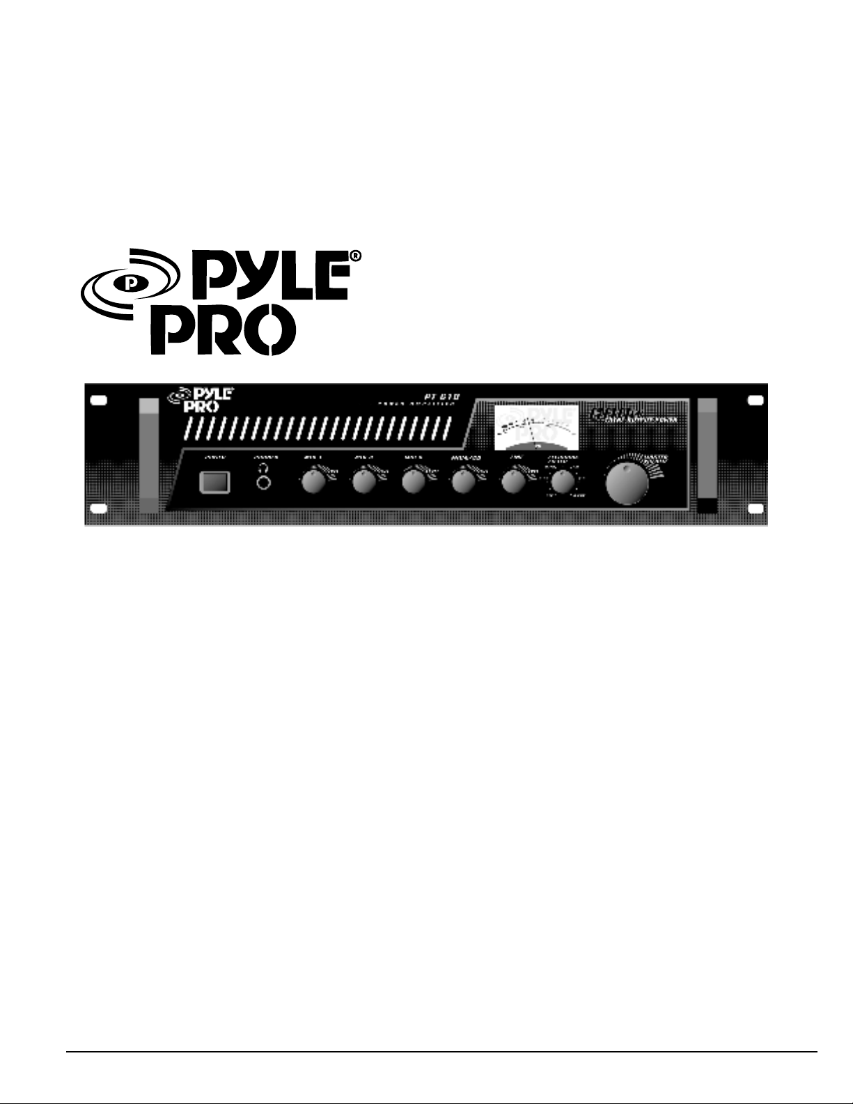
PT610 Amplifier
Page 2

Your new Pyle Pro PT-610 600 Watt
P.A. Amplifier gives you the power and
versatility you need in a professional
sound system. The amplifier’s wide
frequency response makes it suitable
for amplifying music or vocal program
material. It can be used for live bands,
office paging systems, public
annoucement systems, or a variety of
other installations.
TABLE OF CONTENTS
1
Features and controls
2
Installation Guidelines
2
Input Connections
2
Connecting a CD or tape player or tuner
2
Connecting an additional CD sound source
2
Connecting an equalizer or signal processor
2
Connecting microphones
2
Speaker connections
2
Connector options
2
System 1: Single speaker system
3
System 2: Two speakers in series
3
System 3: Two speakers in parallel
3
System 4: Four speakers in series/parallel
4
System 5: Connecting speakers with transformers
4
Using headphones
4
Connecting to AC power
4
Mounting the amplifier
5
Turning the amplifier on
5
Using the power meter
5
Using the master volume control
5
About the internal clip circuitry
5
About the internal protection circuitry
5
About the feedback filter
6
Limited warranty
6
Specifications
Please read this manual thoroughly before you attempt to set up and use the amplifier. It contains a range of
installation suggestions as well as instructions to ensure safe usage. Installed properly, you can expect years of
trouble-free service from this product.
PYLE PRO PT610 Amplifier Owner’s Manual
Page 3

Power Meter
Indicates the output signal level
FEATURES AND CONTROLS
FRONT PANEL
Power On/Off
Phone Jack
Lets you connect a pair of stereo
headphones for private listening
or cueing (monitoring) sound prior
to “airing” it.
Five Input Sources Mixing Controls
Controls the sound level for each of
the audio input sources.
Mic4/CD Input allows you to select
and connect an alternative high level
audio sound for musical and special
effects.
Clip Circuit and Indicator
This special circuitry protects
the amplifier and speaker
system from being damaged
by overdriving power levels.
Indicator lights remind the
user to reduce the volume
when amplifier output is
execessive.
Feedback Filter
Controls the audio freqency.
Master Volume
Lets you adjust the overall sound level
Protection Indicator
This LED is illuminated when a
thermal overload condition is
present.
REAR PANEL
110
110
FUSEFUSE
FUSEFUSE
COM 4Ω 8Ω 16 Ω 70V
COM 4Ω 8Ω 16 Ω 70V
8Ω
8Ω
8Ω GND
8Ω GND
+
+
MIC4 MIC3 MIC2 MIC1
IN
–
–
IN
OUT LINE CD
OUT LINE CD
L
L
R
R
CD MIC
MIC4 MIC3 MIC2 MIC1
Four Microphone Inputs
Allows you to connect up to four balanced or
unbalanced of 6.35mm or XLR type.
Mic4/CD Input
Allows you to select and connect an alternative
high level audio sound for musical and special
effecs.
PYLE PRO PT610 Amplifier Owner’s Manual – 1
Page 4

INSTALLATION GUIDELINES
FUSEFUSE
110
8Ω
+
–
COM 4Ω 8Ω 16 Ω 70V
8Ω GND
IN
OUT LINE C
Input connections
The PT610 accepts a broad range of input sources, including:
Compact Disc (CD) player
Cassette, Reel-to-Reel or other tape player
Radio Tuner
Microphones (up to 4 simultaneously)
Equalizer
Signal Processor
Connecting a CD or tape player or tuner
In a normal installation, one would use the LINE JACK for
connecting a CD player, tape player or tuner
FUSEFUSE
COM 4Ω 8Ω 16 Ω 70V
8Ω
8Ω GND
110
+
IN
–
OUT LINE CD
MIC4 MIC3 MIC2 MIC1
L
R
CD PLAYER
Connecting an additional CD sound source
In this situation, use the MIC4 JACK, and set the MIC4/CD
SELECTOR switch to the CD position.
Switch in “CD” position.
FUSEFUSE
COM 4Ω 8Ω 16 Ω 70V
8Ω
8Ω GND
110
+
IN
–
OUT LINE CD
MIC4 MIC3 MIC2 MIC1
L
R
Speaker connections
One or more speakers (4, 8 or 16 Ohm) speakers can be
connected to the amplifier with or without transformers.
However, before you connect any speakers to the amplifier,
the total speaker impedance must be calculated in order
to avoid damage to the amplifier. A total speaker impedance
greater than 16 Ohms or less than 4 Ohms can cause this
damage to occur.
To begin with, in order to ensure equal volume from each
speaker, all connected speakers should have the same
impedance.
A proper total impedance within the 4 to 16 Ohm range can
be acheived by combining series and parallel speaker
connections. Please see the diagrams which follow which
explain how to accomplish this.
Finally, always use the shortest length of speaker wire
possible of proper gauge. Usually, 18 gauge wire is adequate
for lengths under 25 feet, while 16 gauge is used for greater
lengths.
Connector options
The PT-610 offers several different connection points for
speaker hookups. These include screw terminals, a 6.3mm
jack, and a pair of banana plug connectors.
It is not proper or recommended to connect all the speaker
outputs simultaneously. In addition, please note that when
the 6.3mm jack is used, all the screw terminal and RCA
signal outputs are disconnected.
System 1: Single speaker system
CD PLAYER
Connecting an equalizer or external signal processor
Connect the processor’s OUT to the amplifier’s IN, and the
processor’s IN connector to the amplifier’s OUT.
FUSEFUSE
COM 4Ω 8Ω 16 Ω 70V
8Ω
8Ω GND
110
+
IN
–
OUT LINE CD
MIC4 MIC3 MIC2 MIC1
L
R
EQ OR MIXER
Connecting microphones
The MIC IN jacks permit you to connect up to 4 low impedance
microphones. The microphones can be used with either a
6.35mm plug, or a 3-pin XLR type plug.
FUSEFUSE
COM 4Ω 8Ω 16 Ω 70V
8Ω
8Ω GND
110
+
IN
–
OUT LINE CD
MIC4 MIC3 MIC2 MIC1
L
R
1. Connect the speaker (-) terminal to the amplifier COMMON
terminal.
2. Depending on the speaker being used, connect the speaker
(+) terminal to the amplifier 4 Ohm, 8 Ohm or 16 Ohm
amplifier terminal.
THIS EXAMPLE SHOWS A
4 OHM SPEAKER
6.3mm or 3-pin XLRJack
2 – PYLE PRO PT610 Amplifier Owner’s Manual
MIC
Page 5

System 2: Two (or more) speakers in series
FUSEFUSE
110
8Ω
+
–
COM 4Ω 8Ω 16 Ω 70V
8Ω GND
IN
OUT LINE C
FUSEFUSE
110
8Ω
+
–
COM 4Ω 8Ω 16 Ω 70V
8Ω GND
IN
OUT LINE C
FUSEFUSE
110
8Ω
+
–
COM 4Ω 8Ω 16 Ω 70V
8Ω GND
IN
OUT LINE C
System 4: Four speakers in series/parallel combination
1. Connect the LEFT SPEAKER (-) to the amplifier COMMON
terminal.
2. Connect the LEFT SPEAKER (+) to the RIGHT SPEAKER (-).
3. Connect the RIGHT SPEAKER (+) to the amplifier’s 4 Ohm,
8 Ohm or 16 Ohm terminal, depending on the TOTAL
IMPEDANCE of the two speakers. If each speaker has an
impedance of 8 Ohms, the total speaker impedance in this
series configuration is 16 Ohms.
LEFT speaker RIGHT speaker
NOTE: ADDITIONAL SPEAKERS MAY BE INCLUDED IN SERIES, BUT IT IS NECESSARY
TO CALCULATE TOTAL IMPEDANCE, AND CONNECT THE SPEAKER CIRCUIT TO
A TERMINAL OF APPROPRIATE IMPEDANCE. FOR EXAMPLE, IF THREE SPEAKERS
OF 4 OHMS ARE USED, TOTAL IMPEDANCE IS 12 OHMS – YOU SHOULD CONNECT
TO THE 16 OHM TERMINAL.
THIS EXAMPLE SHOWS
4 OHM SPEAKERS, TOTAL
IMPEDANCE IS 8 OHMS
System 3: Two (or more) speakers in parallel
1. Connect the LEFT SPEAKER (-) to the RIGHT SPEAKER (-).
2. Connect both the LEFT SPEAKER (-) and the RIGHT SPEAKER
(-) to the amplifier COMMON terminal.
3. Connect the LEFT SPEAKER (+) to the RIGHT SPEAKER (+).
4. Connect both the LEFT SPEAKER (-) to the RIGHT SPEAKER
(+) to the amplifier 4 Ohm, 8 Ohm or 16 Ohm terminal,
depending on the TOTAL IMPEDANCE of the two speakers. If
each speaker has an impedance of 8 Ohms, the total speaker
impedance in this parallel configuration is 4 Ohms.
1. Group the four speakers in two pairs.
2. Connect one pair of speakers in series (see system 2,
above). Note total impedance in chart below.
3. Connect one pair of speakers in parallel (see system 3,
above). Note total impedance in chart below.
4. Connect the speakers’ (-) terminals to the amplifier
COMMON terminal.
5. Connect the speakers’ (+) terminals to amplifier’s 4 Ohm,
8 Ohm or 16 Ohm terminal, depending on the TOTAL
IMPEDANCE of the four speakers. See the chart below for
some sample system suggestions:
PARALLEL
speaker pair
(net impedance
for pair)
8Ω∗ 8Ω
∗ 4Ω∗
8Ω∗ 8Ω
∗ 4Ω∗
16Ω∗ 16Ω
∗ 8Ω∗
16Ω∗ 16Ω
∗ 8Ω∗
SERIES
speaker pair
(net impedance
for pair)
16Ω∗ 16Ω
PARALLEL
LEFT speaker
NOTE:
This diagram is
for THE FIRST THREE
examples
in chart.
In this case, 4 Ohm
terminal is used.
Your system
impedance may vary
depending on the
impedances of
the individual
speakers, and may
require hookup to
the8or16Ohm
terminals.
8Ω∗ 8Ω
∗ 16Ω∗
∗ 32Ω∗
4Ω∗ 4Ω
∗ 8Ω∗
8Ω∗ 8Ω
∗ 16Ω∗
TOTAL
IMPEDANCE
in this type
system
3.∗Ω
3.∗Ω
∗Ω
∗.∗Ω
SERIES
RIGHT speaker
Use this
amp
terminal
4Ω
4Ω
4Ω
8Ω
PARALLEL
RIGHT speaker
SERIES
LEFT speaker
LEFT speaker RIGHT speaker
THIS EXAMPLE SHOWS
8 OHM SPEAKERS, TOTAL
IMPEDANCE IS 4 OHMS
Series/parallel variations
Although the description above is for combining a series pair and a parallel pair
in a parallel hookup, you may also elect to combine two series pairs in a parallel
hookup. Simply be sure you have properly calculated the total impedance, and
attach the (+) speaker circuit wire to the proper amp terminal. For example,if
you use two pairs of 8 Ohm speakers in series each pair, the impedance for each
pair is 16 Ohms. Connected in parallel to the amp terminals, the TOTAL impedance
is 8 Ohms, so you should connect these to the 8 Ohm terminal.
PYLE PRO PT610 Amplifier Owner’s Manual -3
Page 6

Limited Warranty
All PYLE PRO products are carefully constructed and tested before
shipment. Units purchased in the USA are warranted to be free of
defects in material and workmanship for five (2) years from the date
of purchase. This warranty is limited to the original retail purchaser
of the amplifier.
Should the unit fail due to factory defects in material or workmanship,
your unit will be repaired or replaced at the sole discretion of PYLE.
To obtain warranty service, you must first call our Consumer Return
Hotline at (718) 236-6948 to obtain a Return Authorization Number.
This R.A. # must appear on the outside of your package and on all
paperwork relating to your return.
When returning the unit to us for warranty service, it must be carefully
packed and shipped, prepaid, to:
PT610 Specifications
Output Power
at THD 2%, 8-Ohm Load, 1 kHz
Maximum Power, 8-Ohm Load
Maximum Output, 4-Ohm Load
THD at 70W, 8-Ohm Load, 1 kHz, w/bandpass filter
MIC (phone/XLR jack)
CD
Line
Frequency Response
MIC (phone/XLR jack)
CD
Line
(at 1 Watt, +/- 3 dB)
75 Hz–20 kKz
60 Hz–20 kHz
60 Hz–20 kKz
100W
200W
600W
0.35%
0.20%
0.20%
R.A.#: _____________
PYLE PRO Service Center
1600 63rd Street
Brooklyn, NY 11204
You must also include the following items with your return:
• A copy of your sales receipt or other proof of purchase
• A brief letter, indicating the problem you are experiencing
with the product
• Include in your letter your return address, daytime phone
number and R.A. number
• Also include a check or money order for $15.00 for return
shipping, handling and insurance, or provide your Visa/MC
number with expiration date.
Our obligation under this warranty is limited to the repair or replacement
of the defective unit when it is returned to us prepaid. This warranty
will be considered void if the unit was tampered with, improperly
serviced or subject to misuse, neglect or accidental damage.
Name
Address
Purchased at:
Catalog Merchandiser
Music Products Store
Date of Purchase
Model No. Serial #
City, State ZIP
within 10 days.
warranty, please mail this card
product. To activate your
Thank you for purchasing this PYLE
Input Sensitivity
(at 2% THD, 1 kHz)
MIC
CD
Line
Signal-to-Noise Ratio
MIC
CD
Line
Notch Filter Effect
Range
Depth
Noise Level
(with inputs shorted)
Power Requirement
Power Fuse
Dimensions
(mm)
HxWxD,inches
Weight, lbs (kg)
1mV
150 mV
150 mV
60 dB
73 dB
73 dB
300 Hz–3 kHz
–12 dB
0.75 mV
120V AC, 60 Hz
3A/250V
4 3/16 x19x12
(100 x 483 x 306)
22.3 (10.1)
Other
Sound Contractor/Installer Mail Order
PYE PRO AMPLIFIERS
warranty registration card
(if available)
PYLE PRO PT610 Amplifier Owner’s Manual – 6
 Loading...