

Page 1
Owner’s Manual
PYLE PRO AMPLIFIERS
warranty registration card
Thank you for purchasing this PYLE
product. To activate your
warranty, please mail this card
within 10 days.
Name
Address
City, State ZIP
Model No. Serial # (if available)
Date of Purchase
Purchased at:
Music Products Store
Catalog Merchandiser
Sound Contractor/Installer Mail Order
Other
Please complete warranty card, detach and return
All PYLE PRO products are carefully constructed and tested before
shipment. Units purchased in the USA are warranted to be free of
defects in material and workmanship for two (2) years from the date
of purchase. This warranty is limited to the original retail purchaser
of the amplifier.
Should the unit fail due to factory defects in material or workmanship,
your unit will be repaired or replaced at the sole discretion of PYLE.
To obtain warranty service, you must first call our Consumer Return
Hotline at (718) 236-6948 to obtain a Return Authorization Number.
This R.A. # must appear on the outside of your package and on all
paperwork relating to your return.
When returning the unit to us for warranty service, it must be carefully
packed and shipped, prepaid, to:
R.A.#: _____________
PYLE PRO Service Center
1600 63rd Street
Brooklyn, NY 11204
You must also include the following items with your return:
• A copy of your sales receipt or other proof of purchase
• A brief letter, indicating the problem you are experiencing
with the product
• Include in your letter your return address, daytime phone
number and R.A. number
• Also include a check or money order for $20.00 for return
shipping, handling and insurance, or provide your Visa/MC
number with expiration date.
Our obligation under this warranty is limited to the repair or replacement
of the defective unit when it is returned to us prepaid. This warranty
will be considered void if the unit was tampered with, improperly
serviced or subject to misuse, neglect or accidental damage.
Limited Warranty
www.pyleaudio.com
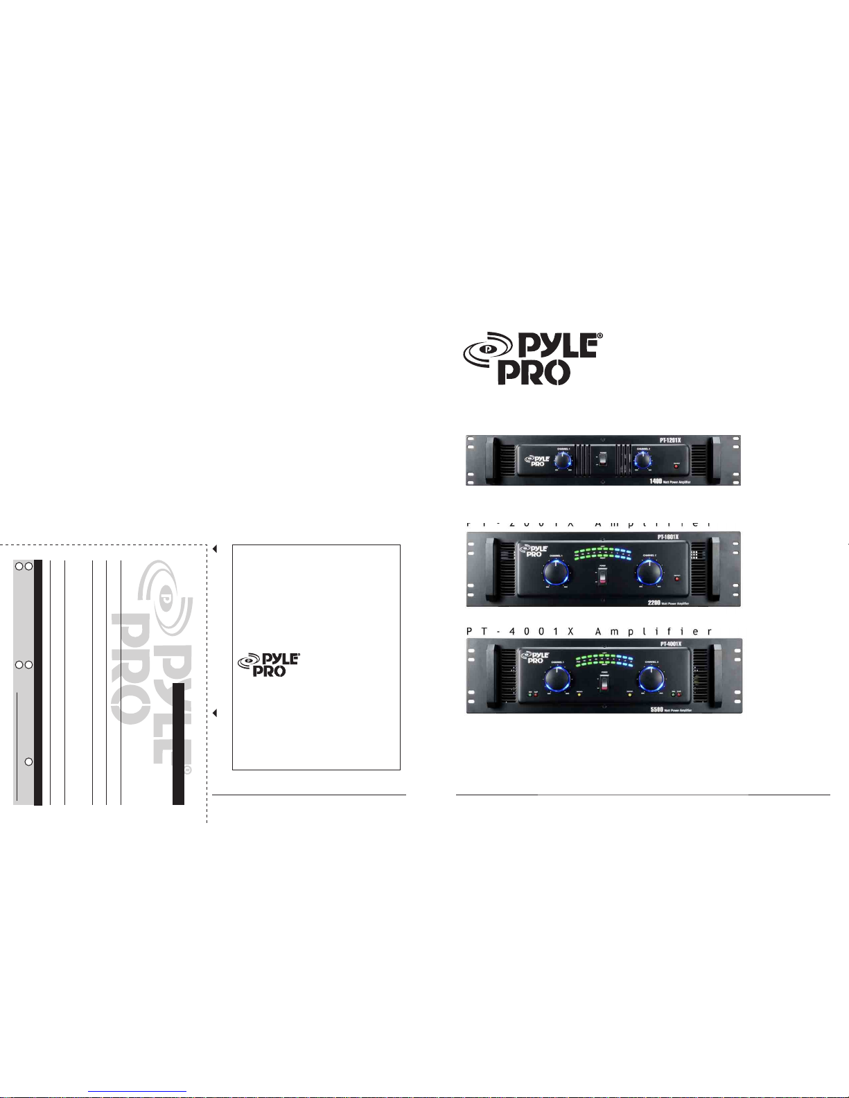
PT-1201X Amplifier
PT-4001X Amplifier
PT-1601X Amplifier
PT-2001X Amplifier
Page 2
FEATURES AND CONTROLS
1 Features and Controls, PT-1201X/1601X and PT-2001X/4001X
3 Installation Guidelines
3 Input Connections
3 Connecting a CD, DVD or tape player or tuner
3 Connecting an equalizer or signal processor
4 Stereo or Mono Inputs
4 Speaker connecitons
5 Bridged Mode Operation
6 Connecting to standard AC power
6 Mounting the amplifier
6 Turning the amplifier on
6 Using the power LED meter
6 Caring for your Pyle Pro Amplifier
6 Using the channel1 and channel2 output level controls
6 About the internal clip circuitry
7 Specifications
7 Limited warranty
TABLE OF CONTENTS
Please read this manual throughly before you attempt to set up and use the amplifier. It contains a
range of installation suggestions as well as instructions to ensure safe usage. Installed properly, you
can expect years of trouble-free service from this product.
i PYLE PRO PT-1201X/1601X/2001X/4001X Amplifier Owner’s Manual
FEATURES AND CONTROLS
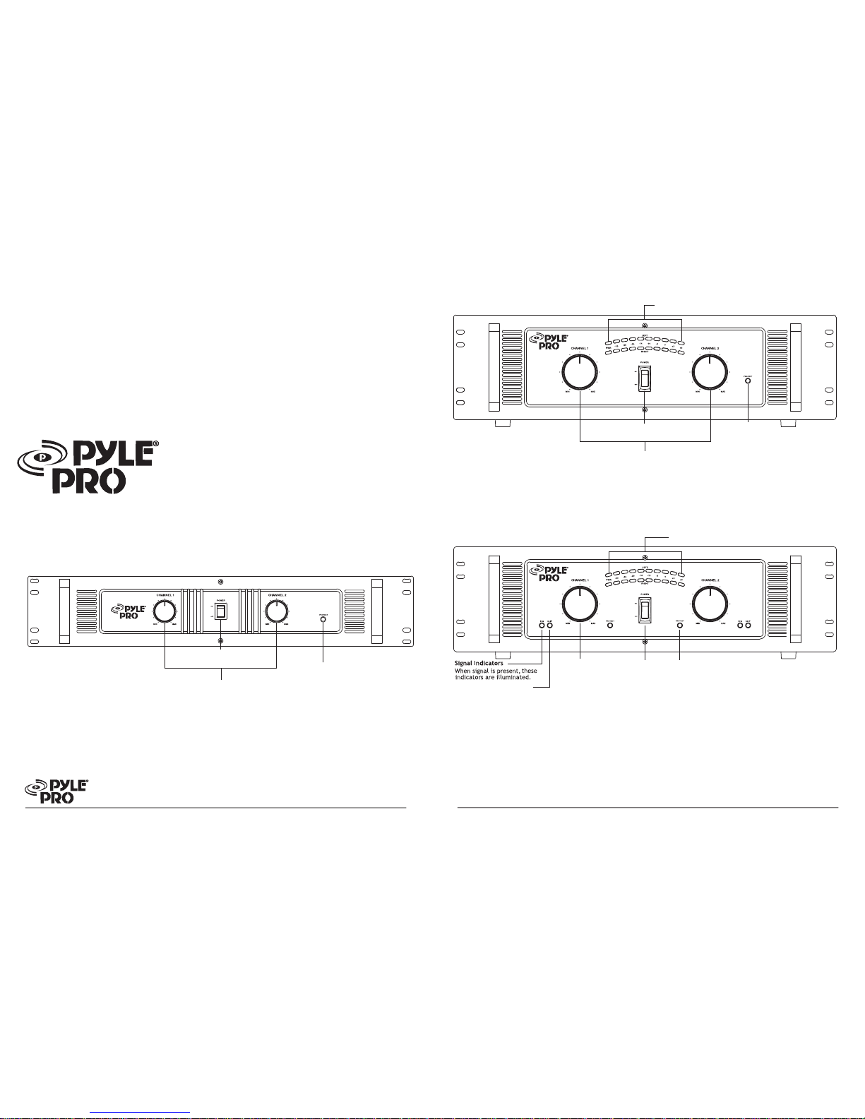
Protection Circuit and Indicator
The indicator will be illuminated when
the amplifier is powered on and at turnon delay status; the indicator will be
turned off after internal outputs are
connected. The indicator will also be
illuminated when the amplifier has
abnormal problems, such as overload
or excessive heat.
FRONT PANEL, PT-1201X
Channel 1 and Channel 2
Output Level Controls
Lets you adjust the sound levels
for each channel.
Power On/Off
Your New Pyle Pro PT series PA
Amplifier gives you the power and
versatility you need in a professional
sound system.
The amplifier's wide frequency
response makes it suitable for
amplifying music or vocal program
material. It can be used for live bands,
office paging systems, public
announcements, or a variety of other
installations.
1-PYLE PRO PT-1201X/1601X/2001X/4001X Amplifier
Owner’s Manual
FRONT PANEL, PT-1601X/2001X
Protection Circuit and Indicator
The indicator will be illuminated when
the amplifier is powered on and at turnon delay status; the indicator will be
turned off after internal outputs are
connected. The indicator will also be
illuminated when the amplifier has
abnormal problems, such as overload
or excessive heat.
Channel 1 and Channel 2
Output Level Controls
Lets you adjust the sound levels
for each channel.
Power On/Off
Channel 1 and Channel 2 Power LED Display
Indicate the output signal level for each channel.
FRONT PANEL, PT-4001X
Protection Circuit and Indicator
The indicator will be illuminated when
the amplifier is powered on and at turnon delay status; the indicator will be
turned off after internal outputs are
connected. The indicator will also be
illuminated when the amplifier has
abnormal problems, such as overload
or excessive heat.
Channel 1 and Channel 2
Output Level Controls
Lets you adjust the sound levels
for each channel.
Clip Circuit and Indicator
This special circuitry protects the amplifier and speaker system
from being damaged by overdriving power levels. Indicator lights
remind the user to reduce the volume when amplifier output is
excessive.
Power On/Off
Channel 1 and Channel 2 Power LED Display
Indicate the output signal level for each channel.
Page 3

LOW CAPACITANCE SHIELDED WIRE
GROUND
SCREW
EQ OR MIXER
3 – PYLE PRO PT-1201X/1601X/2001X/4001X Amplifier Owner’s Manual
INSTALLATION GUIDELINES
Connecting the GND (GROUND) screw terminal Connecting
a mixer or preamplifier may cause excessive noise or hum
in the amplifier output. To prevent this, connect one end
of a low-capacitance shield wire to the amplifier's ground
screw (on the rear panel). Then connect the other end of
this wire to the ground terminal on the mixer or preamplifier
enclosure.
PREAMP OR MIXER
LOW CAPACITANCE SHIELD WIRE
GROUND SCREW
Input connections
These amplifiers accept a board range of input sources,
including Compact Disc (CD,DVD) players; Cassette, Reelto-Reel or other tape players; Radio Tuners; Equalizers;
Signal Processors.
Connecting a CD, DVD, tape player or tuner
In a normal installation, one would use the RCA JACKS for
connecting a CD player, DVD player,tape player or tuner.
Connecting an equalizer or external signal processor
Connect the processor's OUT to the amplifier's IN connector.
PREAMP OR MIXER
LOW CAPACITANCE SHIELD WIRE
GROUND SCREW
REAR PANEL, PT-1201X
Fan Cooling
Cooling system is automatically activated whenever amplifier is turned on.
This forced air cooling system rapidly exhausts interior heat, reducing operating
temperature and aiding performance.
Stereo/Mono Switch
Lets you select conventional
stereo operation with a stereo
input signal or bridged/
mono input mode.
Input Jacks
Let you connect a variety of audio
input sources via the balanced
(XLR/6.35mm phone jack
combinations) or unbalanced (RCA)
inputs.
REAR PANEL, PT-1601X/2001X
Stereo/Mono Switch
Lets you select conventional
stereo operation with a stereo
input signal or bridged/
mono input mode.
Input Jacks
Let you connect a variety of audio
input sources via the balanced
(XLR/6.35mm phone jack
combinations) or unbalanced (RCA)
inputs.
PYLE PRO PT-1201X/1601X/2001X/4001X Amplifier
Owner’s Manual – 2
REAR PANEL, PT-4001X
Fan Cooling
Cooling system is automatically activated
whenever amplifier is turned on. This forced
air cooling system rapidly exhausts interior
heat, reducing operating temperature and
aiding performance.
Stereo/Mono Switch
Lets you select conventional
stereo operation with a stereo
input signal or bridged
/
mono input mode.
Input Jacks
Let you connect a variety of audio
input sources via the balanced
(XLR/6.35mm phone jack
combinations) or unbalanced (RCA)
inputs.
CD PLAYER, DVD , TAPE PLAYER
OR TUNER
use RCA jacks
PREAMP OR MIXER
use XLR/6.35 mm
combo jacks
EQ OR MIXER
CD PLAYER, DVD , TAPE PLAYER
OR TUNER
EQ OR MIXER
use RCA jacks
use XLR/6.35 mm
combo jacks
EQ OR MIXER
EQ OR MIXER
use RCA jacks
use RCA jacks
use XLR/6.35 mm
combo jacks
EQ OR MIXER
CD PLAYER, DVD , TAPE PLAYER
OR TUNER
use RCA jacks
use XLR/6.35 mm
combo jacks
EQ OR MIXER
use XLR/6.35 mm
combo jacks
Page 4

CAUTION:
FOR CONTINUED PROTECTION AGAINST RISK OF FIRE
REPLACE ONL
Y WITH SAME TYPE FUSE.
DISCONNECT SUPPLY CORD BEFORE CHANGING FUSE.
CAUTION:
EQ OR MIXER
EQ OR MIXER
SWITCH IN “STEREO” POSITION
STEREO OPERATION
STEREO SIGNAL SOURCE
CH 2
CH 1
Bridged Mode Operation
This amplifier can operate in a mono bridged output mode, if
your speakers can handle the following power output levels:
As shown in the diagram below, connect the speaker's positive
(+) to the amplifier's red speakers left (1/2) terminals and
negative (-) to red speakers right (1/2) terminals.
The speaker right (+) on the amplifier is used as a negative (-)
terminal for a bridged connection.
NOTE: The extra amplifier output of 6.35mm phone
jacks can not be used for the bridged connection. It can only
be used in normal (non-bridged) operation as a stereo speaker
output.
MONO SIGNAL SOURCE
USE
CHANNEL 1
INPUT ONLY
CH 2
CH 1
MONO SIGNAL SOURCE
USE
CHANNEL 1
INPUT ONLY
SWITCH IN “BRIDGED” POSITION
MONO BRIDGED OPERATION
DO NOT USE
BLACK TERMINALS
5 - PYLE PRO
PT-1201X/1601X/2001X/4001X Amplifier
Owner’s Manual
SWITCH IN “MONO” POSITION
MONO OPERATION
Speaker connections
You can connect 4 Ohm, 8 Ohm or 16 Ohm speakers to
Channel 1 and/or Channel 2 of the amplifier. If you connect
two pairs of speakers, be sure to follow these guidelines:
• Speakers which are connected to the same channel are
part of a pair, and must be of the same impedance.
• Speakers connected to different channels are NOT part
of a pair, and can be of different impedances.
1. Prepare the speaker wire by removing about 1 inch of
insulation from the end of the speaker wire you intend to
connect to the amplifier. Then twist the exposed wire to
secure all the wire strands.
NOTE: Use 16-gauge speaker wire for lengths up to25
feet; 14-gauge wire for lengths over 25 feet. It is
recommended that you use the shortest length of wire
possible.
2. Connect the speaker wires to the speaker's positive and
negative terminals.
NOTE: Most speaker terminals are either color-coded
or have a mark that indicates the terminal's polarity.
Usually positive terminals are red or have a plus symbol
(+), and negative terminals are black or have a minus
symbol (-).
3. Connect the speaker wires to the amplifier's left and
right speaker terminals according to the terminal color
polarity.
Stereo or Mono Inputs
Your Pyle Pro amplifier can be operated in Stereo, Mono or
Bridged mode, depending on the input source. If the input
signal is mono, slide the Stereo/Mono/Bridged selector
switch to MONO and the signal will be routed through both
channels. If you wish to run the amplifier in bridged output
mode, slide the switch to Bridged.
PYLE PRO PT-1201X/1601X/2001X/4001X Amplifier Owner’s Manual - 4
CAUTION! Do not use
balanced and unbalanced
inputs simultaneously!!
CH 2
CH 1
CH 2
CH 1
CAUTION! Do not use
balanced and unbalanced
inputs simultaneously!!
MONO SIGNAL SOURCE
USE
CHANNEL 1
INPUT ONLY
CH-2 CH-1
CH-2 CH-1
OUTPUTS
CH-2
GND
CAUTION
TO PREVENT ELECTRIC SHOCK DO NOT USE THIS (POLARIZED)
PLUG WITH
AN EXTENSION CORD RECEPTACLE
OR OTHER OUTLET UNLESS THE BLADES CAN BE FULLY
INSERTED TO PREVENT BLADE EXPOSURE
CAUTION:
BRIDGE
CH-1
GROUND LIFT
GROUND LIFT
INPUTS
MONO
STEREO BRIDGE
12
3
HOT(+)
COLD(
-
)
GND(+)
BALANCED INPUTS
RISK OF ELECTRIC SHOCK
DO NOT OPEN
AC 120V 60HZ
~
CAUTION:
FOR CONTINUED PROTECTION AGAINST RISK OF FIRE
REPLACE ONL
Y WITH SAME TYPE FUSE.
DISCONNECT SUPPLY CORD BEFORE CHANGING FUSE.
CAUTION:
STEREO SIGNAL SOURCE
CAUTION! Do not use
balanced and unbalanced
inputs simultaneously!!
CH 2
CH 1
CH-2 CH-1
CH-2 CH-1
OUTPUTS
CH-2
GND
CAUTION
TO PREVENT ELECTRIC SHOCK DO NOT USE THIS (POLARIZED)
PLUG WITH
AN EXTENSION CORD RECEPTACLE
OR OTHER OUTLET UNLESS THE BLADES CAN BE FULLY
INSERTED TO PREVENT BLADE EXPOSURE
CAUTION:
BRIDGE
CH-1
GROUND LIFT
GROUND LIFT
INPUTS
MONO
STEREO BRIDGE
12
3
HOT(+)
COLD(
-
)
GND(+)
BALANCED INPUTS
RISK OF ELECTRIC SHOCK
DO NOT OPEN
AC 120V 60HZ
~
STEREO SIGNAL SOURCE
CH 2
CH 1
MONO SIGNAL SOURCE
USE
CHANNEL 1
INPUT ONLY
DO NOT USE
BLACK TERMINALS
MONO SIGNAL SOURCE
USE
CHANNEL 1
INPUT ONLY
use RCA jacks
use XLR/6.35 mm
combo jacks
CAUTION:
FOR CONTINUED PROTECTION AGAINST RISK OF FIRE
REPLACE ONL
Y WITH SAME TYPE FUSE.
DISCONNECT SUPPLY CORD BEFORE CHANGING FUSE.
CAUTION:
DO NOT USE
BLACK TERMINALS
MONO SIGNAL SOURCE
USE
CHANNEL 1
INPUT ONLY
CH-2 CH-1
CH-2 CH-1
OUTPUTS
CH-2
GND
CAUTION
TO PREVENT ELECTRIC SHOCK DO NOT USE THIS (POLARIZED)
PLUG WITH AN EXTENSION CORD RECEPTACLE
OR OTHER OUTLET UNLESS THE BLADES CAN BE FULLY
INSERTED TO PREVENT BLADE EXPOSURE
CAUTION:
BRIDGE
CH-1
GROUND LIFT
GROUND LIFT
INPUTS
MONO
STEREO BRIDGE
12
3
HOT(+)
COLD(
-
)
GND(+)
BALANCED INPUTS
RISK OF ELECTRIC SHOCK
DO NOT OPEN
AC 120V 60HZ
~
Page 5
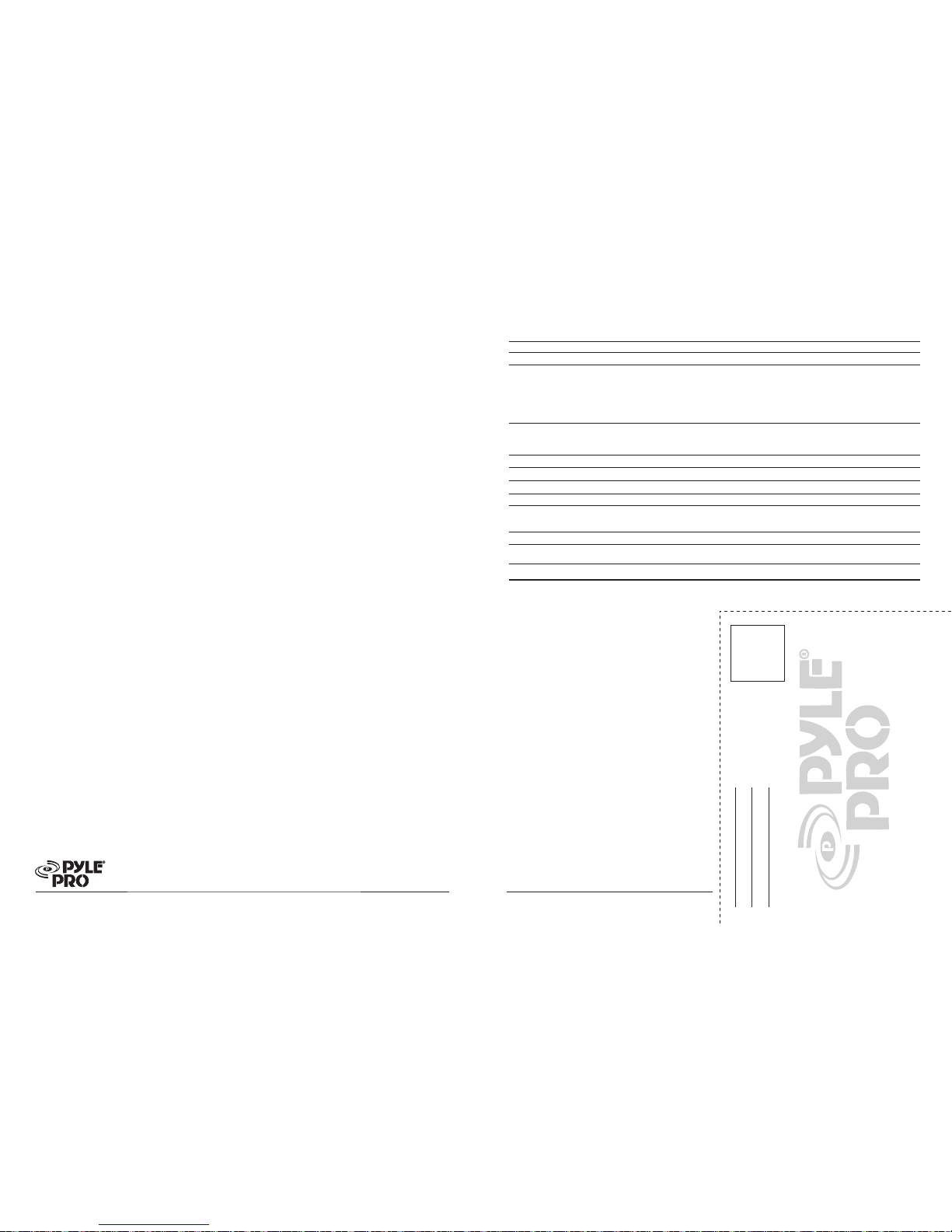
Amplifier Specifications
Input Impedance, balanced (unbalanced)
Continuous Output Power
Stereo Mode
20 Hz to 20 kHz, 8 Ohms
1 kHz, 4 Ohms
Maximum Power, 8 Ohms
Maximum Power, 4 Ohms
Peak Power, 8 Ohms
Bridged Mode
20 Hz to 20 kHz, 8 Ohms
1 kHz, 8 Ohms
Peak Power
THD
at rated output power
Frequency Response +/– 3 dB
Input Sensitivity for rated output power
Signal-to-Noise Ratio A-Weighted
Speaker Impedance
Stereo
Bridged
Power Requirement
Dimensions H x W x D, inches
(mm)
Weight, lbs (kg)
120 VAC, 60 Hz / 230 VAC, 50 Hz 120 VAC, 60 Hz
PYLE PRO
PT-1201X/1601X/2001X/4001X Amplifier
Owner’s Manual - 6 7 - PYLE PRO
PT-1201X/1601X/2001X/4001X Amplifier
Owner’s Manual
PYLE PRO Audio, Inc.
1600 63rd Street
Brooklyn, NY 11204
Place
Stamp
Here
Connecting to standard AC power
After making all other connections, set the POWER switch
to OFF position. Then connect the power cord to a standard
AC outlet.
Mounting the amplifier
This amplifier is designed to accept standard rack mounting
installations. Two slots on each end of the front panel make
it suitable for such an installation.
Tightly secure four mounting screws (not supplied) through
these fours slots and into your standard electronics equipment
rack.
Turning the amplifier on
1. Turn on the audio input source equipment which is
connected to the amplifier INPUT jacks.
2. Set the amplifier’s Channel 1 and Channel 2 output level
gain controls to the minimum level settings.
3. Push in the power switch to turn the amplifier on.
Using the power blue LED meters (without PT1201X)
The meter pointer position indicates the amplifier output
power. For ease of reading in dark environments, the meter
is illuminated.
Using the Channel 1 and Channel 2 Output Level controls
Rotate output level gain clockwise to increase, or counterclockwise to decrease the output power. To get the best
performance with the least sound distortion, always adjust
the output level gain so the meter's pointer does not
continuously exceed the extreme right of the meter's scale.
CAUTION: It is possible to overdrive the amplifier by
setting output level gain too high, which may cause
damage or failure.
About the internal clip circuitry
(without PT-1201X/1601X/2001X)
Special clip circuitry incorporated into your Pyle Pro
amplifier’s design protects the amplifier and speaker system
from being damaged from overdriving power.
Under normal conditions, the amplifier’s clip indicator will
flicker as the output power momentarily exceeds the level
as set by the output level gain selector.
However, under excessive output conditions, the clip
indicator lights remain on continuously, alerting you that
the special clip circuitry has become active. When this
occurs, you should simply reduce the output power level
by rotating the Master Volume control counterclockwise.
20 k-Ohms (10 k-Ohms)
70W x 2
110W x 2
100W x 2
130W x 2
700W x 2
175W x 1
200W x 1
1400W x 1
0.1%
10 Hz to 50 kHz
1.0V
100 dB
4-16 Ohms
8-16 Ohms
3
7/16 x 19 x 10 3/4
(88 x 482 x 273)
18.7 (8.5)
PT-1201X
20 k-Ohms (10 k-Ohms)
120W x 2
170W x 2
160W x 2
210W x 2
1100W x 2
270W x 1
320W x 1
2200W x 1
0.1%
10 Hz to 50 kHz
1.0V
100 dB
4-16 Ohms
8-16 Ohms
5
3/16 x 19 x 12
(132 x 482 x 304)
22.88 (10.4)
PT-1601X
Caring for your Pyle Pro Amplifier
Your Pyle Pro Amplifier is an example of superior design
and craftsmanship. The following suggestions will help you
care for your amplifier so you can enjoy years of use:
• Keep the amplifier dry. If it gets wet, wipe immediately.
• Use the amplifier only in well-ventilated installations.
• Handle the amplifier gently and carefully - do not drop!
• Keep the amplifier away from dust and dirt.
• Wipe occasionally with a damp cloth to keep it looking
new. Do not use harsh chemicals, solvents or
detergents!
20 k-Ohms (10 k-Ohms)
170W x 2
230W x 2
220W x 2
260W x 2
1650W x 2
380W x 1
440W x 1
3300W x 1
0.1%
10 Hz to 50 kHz
1.0V
100 dB
4-16 Ohms
8-16 Ohms
5
3/16 x 19 x 12
(132 x 482 x 304)
24.64 (11.2)
PT-2001X
20 k-Ohms (10 k-Ohms)
260W x 2
400W x 2
300W x 2
450W x 2
2750W x 2
700W x 1
800W x 1
5500W x 1
0.1%
10 Hz to 50 kHz
1.0V
100 dB
4-16 Ohms
8-16 Ohms
5
3/16 x 19 x 13
(132 x 482 x 330)
33 (15)
PT-4001X
 Loading...