

Page 1
PMXU48BT - PMXU68BT
Wireless BT Studio Mixer
Pro Audio Digital DJ Audio Mixer Console
(+48V Phantom Power)
Page 2
One Year Warranty Period
This product is guaranteed for no material or workmanship defects within one
year's period from the purchase date of the original buyer. To ensure the highlevel performance of the property and reliability in the design and manufacture
of this appliance, PLEASE READ THE USER'S MANUAL BEFORE OPERATION.
In case of malfunction, please inform immediately and return the machine with
defects to us, or our authorized agent, and go reparing according to the
following conditions
Within the warranty period
Warranty Conditions
The device must be installed and operated according to the instructions of this
manual. The device hasn't gone through any intentional or unintentional
mistaken uses, neglects or alterations which are described in this manual, or
authorized by us. Any necessary adjustment, correction or repairing should be
carried out by us or any authorized agent of this device.
Please attach the purchase proof with freight prepaid when you return the
defective machine to us or our authorized agent. The machine returned should
be packed well and avoid possible damages on the way of transit. In some area,
these stipulations may vary. Concerning with any possibly adoptive additional
warranty clauses, please contact our sales agent.
NOTICE
To avoid the possibility of malfunction/damage to the product, damage to
data, or damage to other property, follow the notices below.
If there is reason to believe that condensation might have occurred, leave the
device for several hours without turning on the power until the condensation
has completely dried out.
• Avoid setting all equalizer controls and faders to their maximum. Depending
on the condition of the connected devices, doing so may cause feedback and
may damage the speakers.
• Do not apply oil, grease, or contact cleaner to the faders.
Doing so may cause problems with electrical contact or knob motion.
• When turning on the AC power in your audio system, always turn on the power
amplier LAST, to avoid speaker damage. When turning the power o, the
power amplier should be turned o FIRST for the same reason.
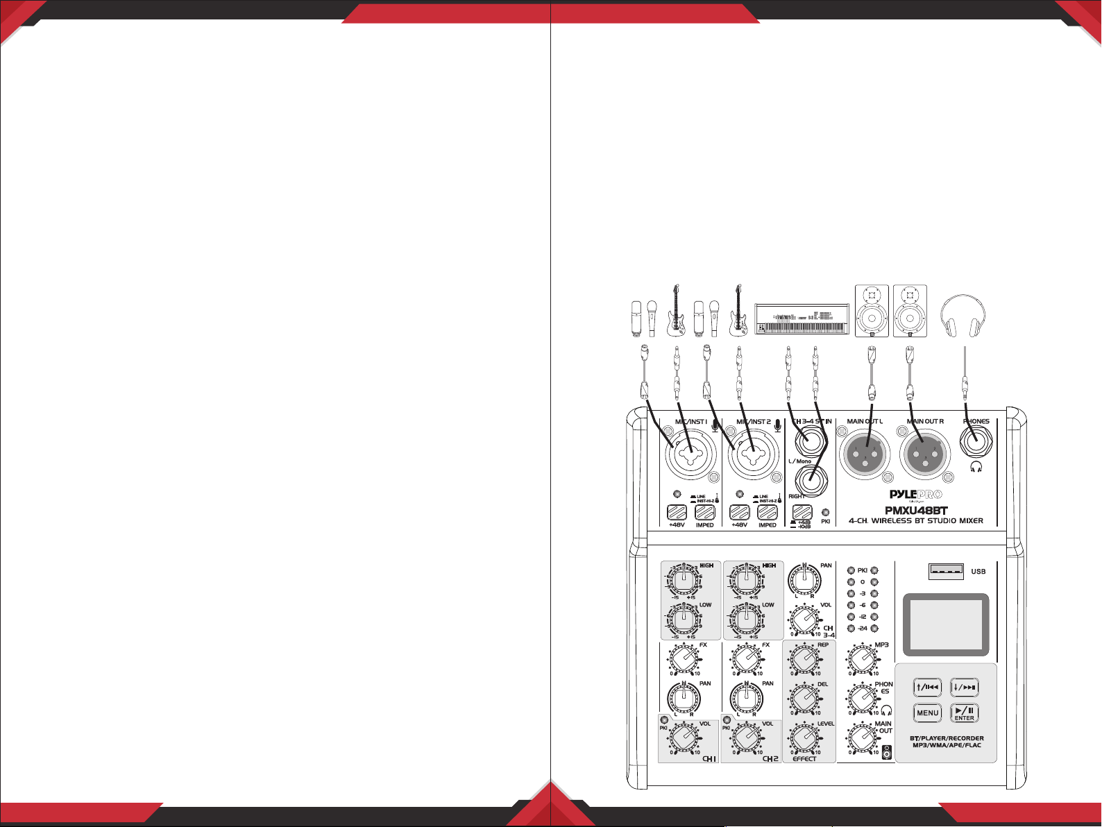
Schematic diagram of equipment connection
Handling and Maintenance
• Do not use the device in the vicinity of a TV, radio, stereo equipment, mobile
phone, or other electric devices. Otherwise, the device, TV, or radio may
generate noise.
• Do not expose the device to excessive dust or vibration, or extreme cold or
heat (such as in direct sunlight, near a heater, or in a car during the day), in
order to prevent the possibility of panel disguration, unstable operation, or
damage to the internal components.
• Do not place vinyl, plastic or rubber objects on the device, since this might
discolor the panel.
• When cleaning the device, use a dry and soft cloth. Do not use paint thinners,
solvents, cleaning uids, or chemical impregnated wiping cloths.
• Condensation can occur in the device due to rapid, drastic changes in ambient
temperature-when the device is moved from one location to another, or air
conditioning is turned on or o, for example. Using the device while conden
sation is present can cause damage.
www.PyleUSA.com
2
www.PyleUSA.com
3
Page 3
Front panel function
Front panel function
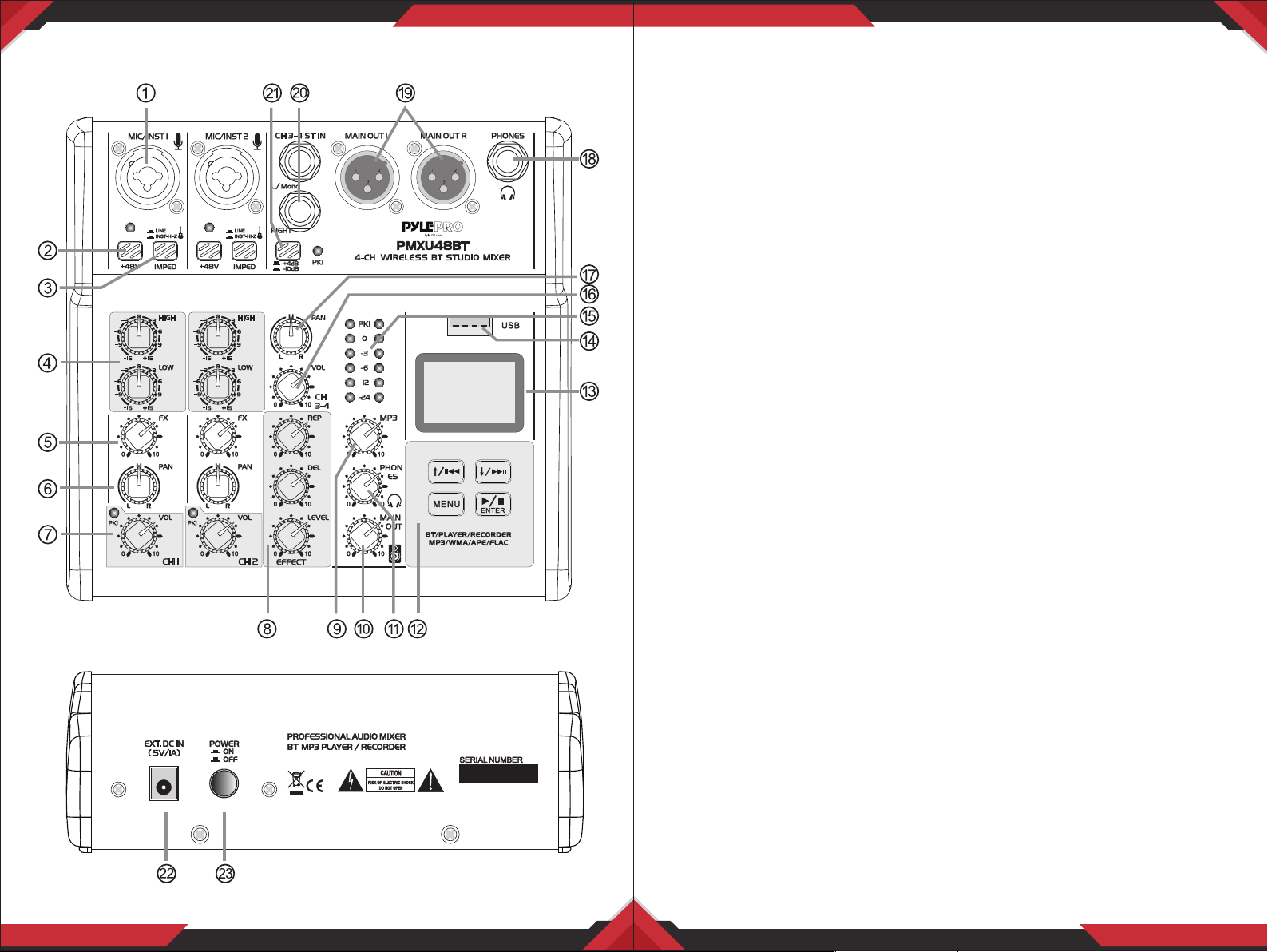
1. Mike/Line/Guitar input jacks of MIC channel: The jacks are used to connect
microphones or other audio devices in support of cannon plugs and 6.35 plugs.
2. +48V phantom switch/LED: When this switch is turned on, the +48V LED
lights and DC +48 V phantom power is supplied to the XLR plug on MIC input
jack.
NOTICE
Be sure to leave this switch o if you do not need phantom power. Follow the
important precautions below, in order to prevent noise and possible damage to
external devices as well as the mixer if you turn this switch on. Be sure to leave
this switch o when you connect a device that does not support phantom power
to channel. Make sure to turn this switch o when connecting/disconnecting a
cable to/from channel. Slide the knob on channel to minimum before turning
this switch on/o.
3. Guitar/Line input shifter: The switch is used to shift the connections to
dierent sound sources of the input channels. Switched up, the input channel
can be connected directly with a high impedance audio device such an electric
guitar or a bass. Switched down, it can be connected to a low-impedance
sound device.
Warning!
In operation of the switch, all level output control (such as channel volume knobs,
monitor output knobs and earphone knobs) should be set up to the minimum
position. Because this operation will cause a sudden impact sound, which can
damage the external devices, and the hearing of the personnel on site.
www.PyleUSA.com
4
4. Mic input CH 2 band EQ: This is a high quality, sensitive, 2 segment equalizer
that adjusts the overall tone of the channel. The adjustment wave form of the
high and low bass equalizer is the shape of the broom, which aects the
frequency of 12KHz and the sound below 80Hz;
5. FX send knob: Adjust the size of the signal sent to the digital eect processor.
The signal transmitting point is located after the volume knob of the channel;
6. PAN knob: Positions the channel signal between L/R in the stereo mix;
7. MIC input volume knob/peak LED: Adjust the volume of the sound input
from the microphone or other source connected to channel. When the peak
light ashes, indicating that the input signal is too high, please turn the
volume knob to the left to reduce the volume. In normal use, please avoid the
peak light for a long time;
www.PyleUSA.com
5
Page 4

8. Digital eect processor adjusts the knob:
REP: adjust how many times the echo repeats;
DEL: adjust the time interval between each echo.
LEVEL: adjust the volume of the eect processor.
9. MP3 audio signal volume knob: Adjust the audio signal level from the MP3
player;
10. MAIN output volume knob
11. Phones output volume knob
12. MP3 Player/Recorder controlled keyboard
13. MP3 Player/Recorder LCD display
14. MP3 Player/Recorder USB port
15. MAIN output level meter
16. The stereo input channel volume knob
17. The stereo input channel balance knob
18. 6.35mm specication for stereo headphone output interrupts
19. MAIN output jacks: XLR balanced output interrupt for the connection of
active speakers, power ampliers or other audio devices.
20. 6.35mm-spec stereo line input jack
21. The stereo line input signal sensitivity selection button, bounce to +4dB,
press 10dB;
22. DC power supply 5V socket
23. Power switch
24. BT/MP3 player/recorder operation instructions:
24.1. Denition of keys
A. Shortly press: the previous one/choose upward or left;
Press and hold: reduce the volume.
B. Shortly press: the next one/choose downward or right;
Press and hold: increase the volume.
C. Menu key;
D. Play/Pause/Conrm key
24.2. System setup: When there is no USB disk inserted, shortly press any
key and enter the main menu items, shortly press the choose key,
select the "system setup" key, press "play conrm key" to do the
system setup.
The list is as follows:
A. Backlight time: After there is not any operation, the backlight will turn o
automatically after some certain time.This selection item is for you to choose
the time you need to turn o. The default is not turn-o.
B. Language selection: English or Chinese menu display.
C. Contrast: Adjust the contrast degree of the display screen, and suit dierent
light environment.
24.3. Start the BT connection: When there is no USB disk inserted, shortly
press any key, and enter the main menu item.
Shortly press the selection key, and select the "BT mode" item.
Press the "Play conrm key" to connect.
The Bluetooth Network Name is ‘PYLEPRO MIXER’
24.4. Music mode: When the USB disk is inserted, it will start to play the
music automatically. Under the interface of playing music, shortly press
"menu" key, a couple of setups under the music mode will pop up.
A. Circulation mode: there are multiple modes such as all circulation,
single circulation and random play to be chosen.
B. EQ mode: there are a couple of balance modes such as nature, rock,
pop and classic modes to be chosen.
C. Master disc directory: do the reading of audio les in the le folder,
you can choose the music promptly.
D. Delete the le: delete the audio le currently playing.
24.5. Record mode: Under the interface of playing music, press and hold the
"menu" key, and enter the recording work mode:
A. Shortly press "Play" key, start the recording or pause the recording;
B. Long press "Play" key, nish the recording and save the recording le,
automatically quit and return to the play interface;
C. Recording le format: MP3/48Khz sampling/128Kbs bit rate.
24.6. Connect the computer: In the main menu, select and conrm the
"Connecting computer" item. Use the USB cord to connect with the
USB port of the computer. It can be used as the USB sound card to play
the music.
24.7. Any setup changes will be stored and memorized at the time of
switch-o.
www.PyleUSA.com
6
www.PyleUSA.com
7
Page 5
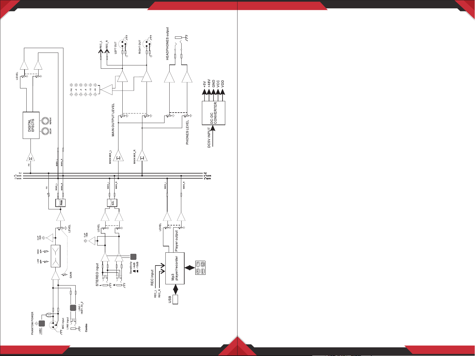
System Block Diagram
PMXU48BT - PMXU68BT
Wireless BT Studio Mixer
Pro Audio Digital DJ Audio Mixer Console (+48V Phantom Power)
PMXU48BT
(2) XLR/14’’ Combo Audio LINE/Microphone Inputs
•
• +48V Phantom Power, Independent Mic Channel
• Audio Mixer Type: 4-Channel
• Total Unit Dimensions (L x W x H): 6.50’’ x 2.59’’ x 6.50’’ -inches
PMXU68BT
(4) XLR/14’’ Combo Audio LINE/Microphone Inputs
•
• +48V Phantom Power Control
• Audio Mixer Type: 6-Channel
• Total Unit Dimensions (L x W x H): 8.70’’ x 2.59’’ x 6.50’’ -inches
Features:
Digital Studio DJ Mixer System
•
• Pro Audio Console Controller
• Multi-Channel Sound Source Mixing
• Microphone, Instrument / Guitar / Keyboard Mix Ability
• Built-in Bluetooth Wireless Streaming Receiver
• USB Interface: MP3 Flash Drive Reader/Computer Connection
• LCD Digital Display & Front Panel Control Center
• ID3 Tag Readout: Display Song Title / Artist
• Connect & Stream Audio from External Devices
• MP3 Digital Audio File Compatibility
• (2) XLR 3-Pin (L/R) MAIN Outputs
• 1/4’’ (6.35mm) Mono / Stereo Inputs
• 1/4’’ (6.35mm) Headphone Jack
• Output Signal Level Indication
• BUS Audio Control, Sound Routing
• Rotary Adjustment Knobs & LED Indicator Lights
• Independent Channel Input Audio Conguration
• Gain, High, Low, FX/Send, Pan Tone Audio Adjustment
• Power ON/OFF Switch
• Used for Professional DJ Studio Applications, Audio Recording, On-Stage
Performances
www.PyleUSA.com
8
www.PyleUSA.com
9
Page 6

What’s in the Box:
• Bluetooth Studio Mixer
• Wall Power Adapter
Wireless Bluetooth Connectivity:
• Hassle-Free Audio Streaming Ability
• Works with All of Today’s Latest Devices
(Smartphones, Tablets, Laptops, Computers, etc.)
• Bluetooth Network Name: ‘PYLEPRO MIXER’
• Bluetooth Version: 2.1
• Wireless Range: Up to 33’+ ft.
Technical Specs:
• CH 1/2 MIC/LINE: Gain: -14+40 dB;
• 2 Band Graphic EQ: 80Hz/12KHz, +15dB
• Audio Level Meter: 2 x 6 Point LED Display
• Max Output Level: 3 Vrms
• System Gain: -14 +40dB
• Frequency Response: +0.5 dB, 20Hz-20kHz
• Dynamic Range: 102 dB
• THD+N @ 1KHz: <0.03%
• Stereo Crosstalk: 92 dB
• Maximum USB Flash Support: Up to 64GB
• USB Digital Audio File Compatibility File-Types: MP3, WMA, APE, FLAC
• Phantom Power Voltage: +48V
• Power Consumption: Max: 5W
• Power Supply: 120/240V, 5V/1A
Questions? Issues?
We are here to help!
Phone: (1) 718-535-1800
Email: [email protected]
PMXU48BT
PMXU68BT
This product can expose you to a chemical or group of checmicals, which may include
“Nickel Carbonate” which is known in the state of California to cause cancer, birth defects,
or other reproductive harm. For more info, go to https://www.p65warnings.ca.gov/.
www.PyleUSA.com
10
www.PyleUSA.com
11
 Loading...