

Page 1
Owner’s Manual
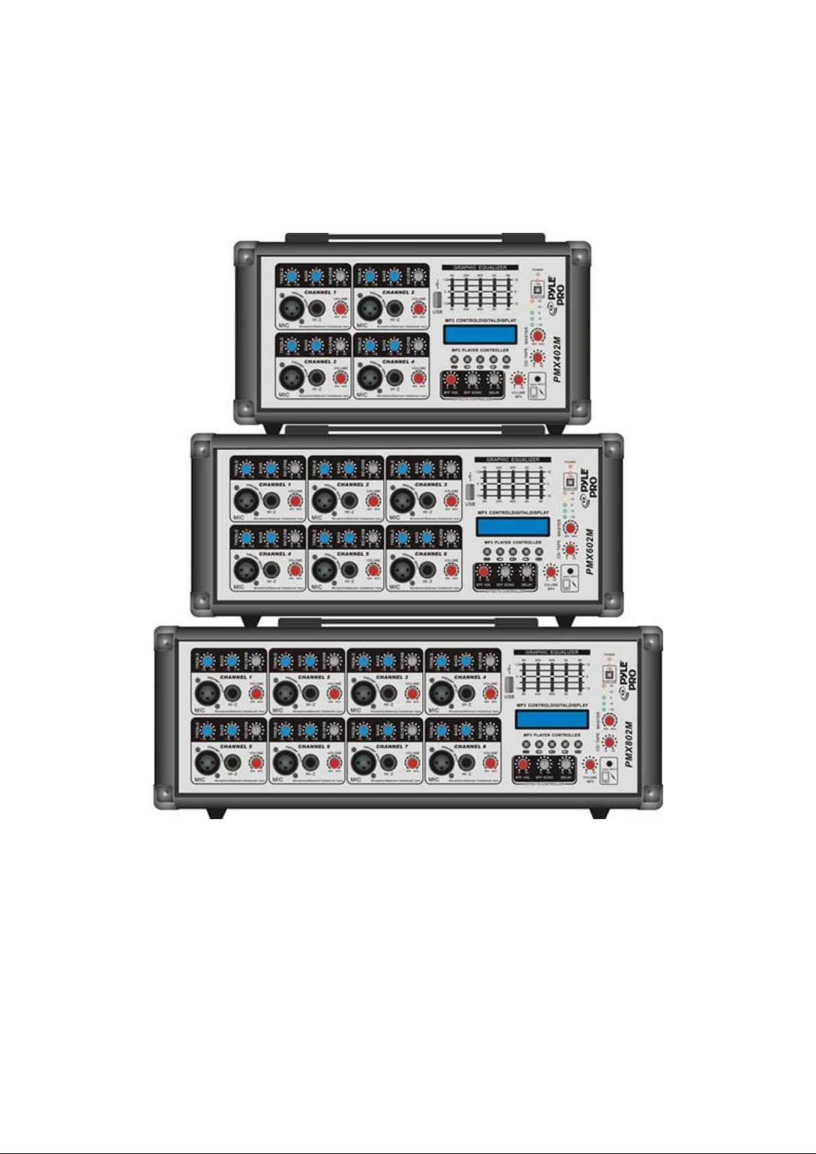
PMX402M 4 CHANNELS
PMX602M 6 CHANNELS
PMX802M 8 CHANNELS
www.pyleaudio.com
1
Page 2
FEATURES
Rugged and easy to operate, PMX402m/602m/802m offers great features and
performance at an extremely affordable price and is ideal for many small venue
applications.
4/6 /8 mono Mic inputs with XLR jacks
4/6/8 ¼” line inputs(CD, Tuner, Tape Deck Etc)
Individual control for each channel
Line out for external amplifier or recording device
Output/Input signals Send/Return for a sound processor or digital
processors
USB Port input with blue LCD display
Shielded internal power supply with 110v 60hz/220v 50hz select switch
SAFETY INSTRUCTIONS
CAUTION: To reduce the risk of electrical shock, do
not remove the cover (or back). No user
serviceable parts Inside; refer servicing to
qualified personnel.
WARNING: To reduce the risk of fire or electrical shock,
do not expose this appliance to rain or
moisture.
This symbol, wherever it
appears, alerts you to the
presence of uninsulated
dangerous voltage.Inside
the enclosure-voltage that
may be sufficient to
constitute a risk of shock.
This symbol, wherever it appears,
alerts you to important operating
and maintenance instructions in
the accompanying literature. Read
the manual.
2
Page 3
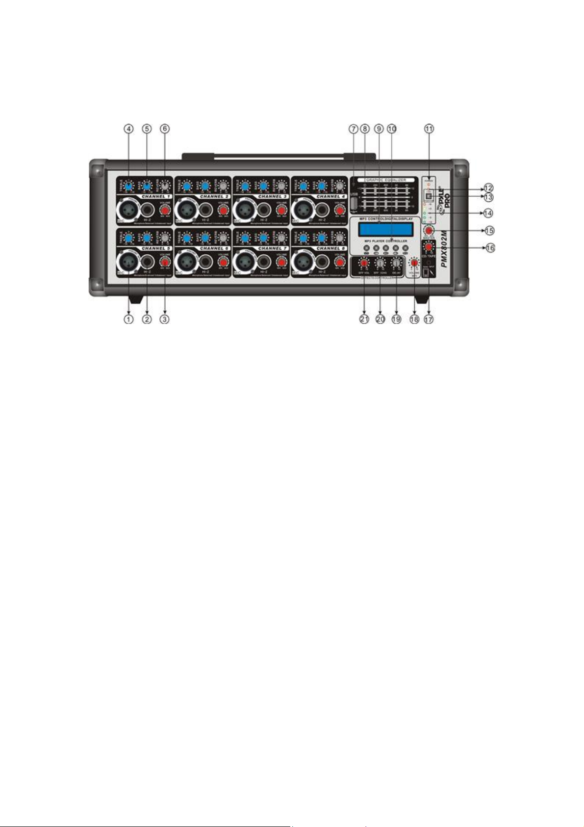
A. FRONT PANEL SECTION FEATURES
1. BALANCED Mic INPUT
Electronic Balanced inputs acceptable a standard XLR male connector. It is designed
to accept a balanced low impedance input signal, Phantom power (15 volts) for
condenser microphones is always on and available. It has an input impedance of 1K
ohm. The connector is wired as: Pin= shield; Pin3= negative (cold).
2. BALANCE INPUT(LINE)
Electronic Balanced inputs acceptable a standard 1/4" jacks connector. It is
designed to accept a balanced high impedance input signal
3. VOLUME
This is function to adjust the volume of a signal connection into each channel and
adjust the volume of output, together with the master fader.
4. TREBLE
This control gives you up to 15 db of boost or cut at 10 kHz and above, and it is also
flat at the detent. Use it to add sizzle to cymbals, and an overall sense of transparency
or edge to key-boards, vocals, guitar, and bacon frying. Turn it down a little to reduce
sibilance, or to hide tape hiss.
5. LOW
This control gives you up to 15 dB boost or cut at 100Hz and below. This circuit is
flat (no boost or cut) at the center detent position. This frequency represents the punch
in bass drums, bass guitar, fat synch patches, and some really serious male singers.
6. EFF
3
Page 4

This is a send control to the reverb bus. It controls the amount of reverberation added
to the input signals.
7. USB PORT
Connect USB disk with MP3 file.
8. GRAPHIC EQUALIZER
5-band equalizer is provided for sound control over each frequency, and for precise
high quality sound by final tone control (60,250,1K,2K,8KHz shelving at +/-12dB).
9. LCD DISPLAY(There are three states show)
a. Machine became the first LCD display screen information trademarks of the
products, USB version, and initial system.
b. The second message is to remind the screen insert USB, or disk is not MP3 format.
c. The third message is the total number of songs in the USB disk, songs of the total
play time ,play time at present, play/pause/ stop sign, symbol cycle, File Format(M
refers to the MP3 file format, W refers to the WMA file format), as well as the EQ.
10. TOUCH BUTTON
Five touch keys, which are single cycle / circle of the total, up, play /pause / stop,
down, EQ option. All of the touch button of this machine are conventional key and
compound key.
a. Symbol cycle (A total of 6 cycle model).
They are All cycle, random play,song cycle , End the end of the single player , cycle
by a player and players here. Through the button to switch modes, according to a time
switch, LCD display the logo.
b. Down.
This is a complex bond, In the state of play, press the button, Will play on a song; In
the state to suspend or stop, press the button, the current song will be re-broadcast;
Press the button for a long time, can adjust the LCD backlight brightness.
c. Play /Pause/ Stop.
This is a conventional bond, the press is a player, next it is time to pause, then it is
stop, while the corresponding LCD display signs. Press for a long time to null and
void
d. Up.
This is a complex bond, In the state of play, press the button, Will play the next song;
Press the button for a long time, can adjust the LCD backlight brightness.
4
Page 5

e. EQ.
This is a conventional keys, press the first choice of a EQ, a total of 11 EQ, are
Natural, Rock, Pop, Class, Jazz, Blue, Hall, Bass, Soft, Country, and Opera.
11. POWER LED
It lights when the power switch turns on.
12. PHANTOM LED
The LED +15V will be turned on when start working.
13. PHANTOM POWER SWITCH
When you press the switch the XLR input will have 15V.
14. OUTPUT LEVEL INDICATOR
This is a level meter which shows output levels.
15. MASTER VOLUME
Use this control, you can adjust signal level of main channel.
16. TAPE
This controls the level of the playback inputs(RCA) jack.
17. IPHONE/AUX INPUT
Portable device input interface. You can plug in a device like an iPhone or
iPod.
18. AUX VOLUME
Use this control, you can adjust the aux input signal level sent to main channel.
19. EFFECTS DELAY
Use this control, you can adjust the delay time interval of echo repeat.
20. EFFECTS REPEAT
Use this control , you can adjust reverberating deepness.
21. EFFECTS LEVEL
Use this control, you can adjust signal levels of echo output.
5
Page 6

B.BACK PANEL SECTION FEATURES
1. SPEAKER JACK
These are 2 conductor 1/4” speaker outputs. Each one is rated at 8 ohm minimum
impedance. Total minimum load for the amplifier is 4 ohms. You may connect either
1-4 ohm,1-8 ohm or 2-8 ohm speaker cabinets. Do not below rated minimum
impedance.
2. SEND/RETURN
Use a stereo ¼” plug to send and return a preamp signal to a sound processor
3-4.TAPE IN AND REC OUT
The TAPE IN allows cassette recorders or CD players to be added to the Main output.
The RECORD OUTPUT, with TAPE RCA jacks, provides signal output to a cassette
deck or Home audio equipment. The impedance is 1K ohms @ -10dBv.
5. FAN
In order to prevent rising the inside temperature, the inside heat is emitted outside.
6. POWER SWITCH
Turns the unit ON or OFF. Always turn level controls down before turning on the
unit.
7. CHANGE-OVER SWITCH
This device is used to 110V/220V or 115V/230V voltage conversion.
8. AC POWER CORD/FUSE HOLDERS
6
Page 7

For selecting the proper voltage (115/230AC) to match the power supply in your area.
Note: To avoid damage to your unit, always make sure this switch is set to the correct
supply voltage. Damage caused by improper use is not covered by the warranty
C. CONNECTIONS
You will need a lot of cables for different purposes – see the following figures to
make sure you have got the right cables. Unbalanced equipment may be connected to
a balanced inputs/outputs. Either use mono 1/4"plugs or connect ring and sleeve of
TRS plugs.
Fig. 5: Balance plug
7
Page 8

Speaker Connections
VERY IMPORTANT — PLEASE READ BEFORE CONNECTING SPEAKERS
One or more speakers (2, 4, or 8 ohm) can be connected to the amplifier with or
without transformers. However, before you connect any speaker to the amplifier, the
total speaker impedance must be calculated in order to avoid damage to the amplifier.
A total speaker impedance greater than 16 ohms or less than 4 ohms can damage your
amplifier. To start, all connected speakers should have the same impedance. Please
refer to the following diagrams for instructions on connecting more than one speaker.
Take special note of the type of connection and the impedance of the connected
speakers.
System type 1: One speaker connection.
8
Page 9

System Type 2: Two or more speakers connected in series.
9
Page 10

System type 2: Two or more speakers connected in series.
10
Page 11

D. APPENDIX
Bandwidth 20Hz to 20kHz±1dB
Input Impedance: Lo-Z Mic 1K ohms
Hi-Z 33K
Mic/Line ohms
Tape 10K
Playback ohms
Input level: Lo-Z Mic -50Db
Hi-Z -20Db
Mic/Line
Tape -10dB
Playback
MODEL NO PMX402M PMX602M PMX802M
CH QTY 4CHANNELS 6CHANNELS 8CHANNELS
DIMENSION 15.75’X12.01’X7.87’ 17.32’X12.01’X7.87’ 20.28X12.01’X7.87’
Specifications:
*With USB 2.0 Terminal and LCD
*5-Band graphic equalizer
*Each channel tone control
*Effect control
*TAPE input, REC output
*Channel tone adjust (high/low+/-15dB)
*AUX/TAPE/effect feedback input
*Effect send
*Master volume control
*Phantom + 15V
Power supply 110V AC 60HZ, SWITCHABLE 220V AC 50HZ
11
 Loading...