

Page 1
Http://www.pyle-pro.com
PEXA Owner's Manual Versio 1.0 01/14/10
PEXA SERIES
PEXA Power Amplifier
Owner's Manual
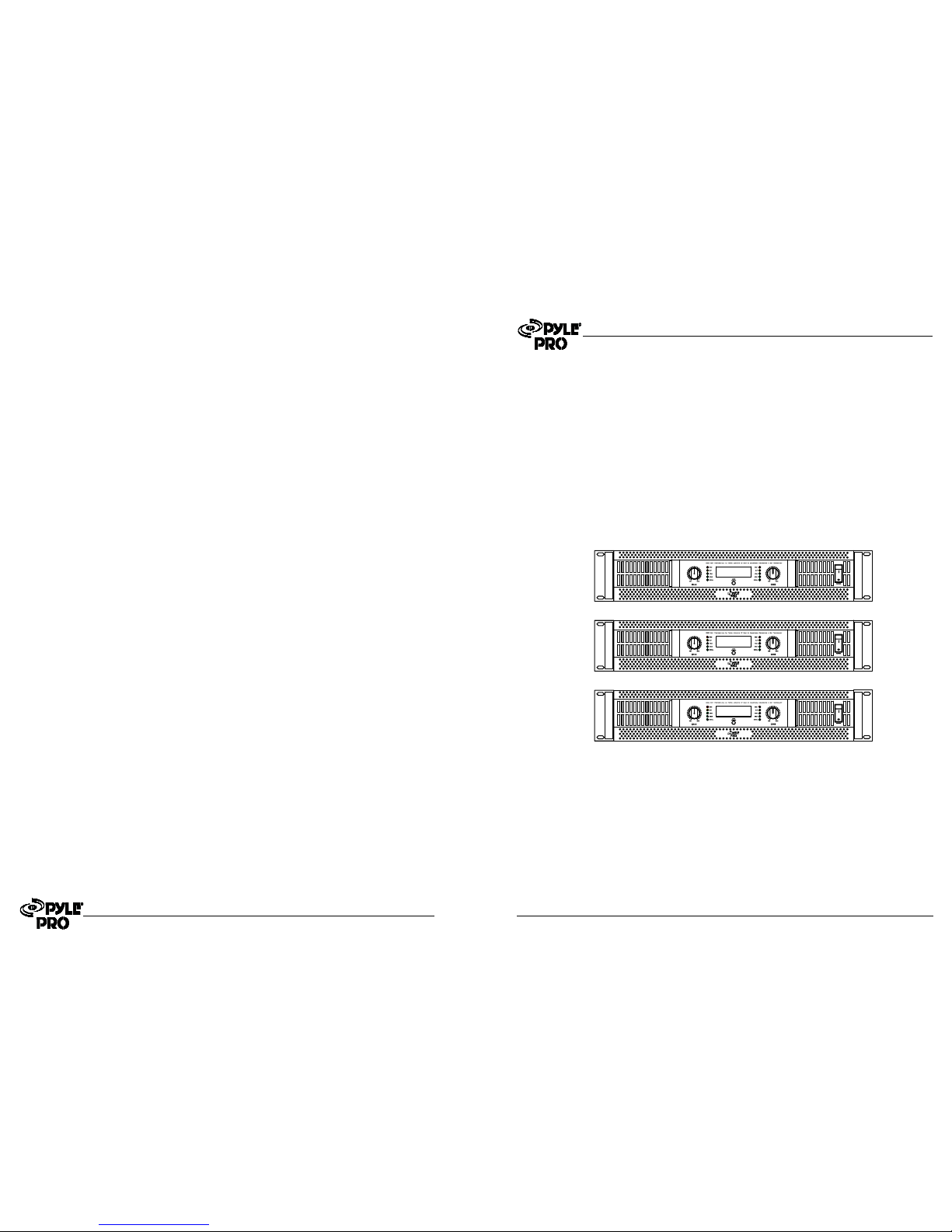
PEXA3000
PEXA8000
PEXA3000
PEXA5000
PEXA5000
PEXA8000
Page 2

Page 1
Table of Contents
2
2
3
4
5
6
7
8
8
Overview
Important SafetyInstructions
Front Panel
Rear Panel
Installation guidelines
Graphic LCDDisplay Screen Explain
TechnicalSpecifications
Generic FaultAnd Solutions
Service
PEXA SERIES
Page 8
PEXA SERIES
FAULT
PROBLEM
SOLUTIONS
No sound
(power
LED off)
AC supply not connected or
switched off
Blown fuse
Check AC connections and switches
Check and replace fuses at plug and IEC
socket. USE ONLY SAME TYPEAND RATING!
NO sound
(Power
LED on)
No input, or input too low
Level controls set too low
Speakers faulty or not connected
Check input is connected, and LED
Increase level controls
Check speakers and speaker connections
Hum or
buzz is
audible
Noise from AC supply is being
picked up in the signal path
There is an earth problem
Use good quality, shielded signal cables and ensure they
are kept away from AC power cables and other AC
powered equipment
Use a mains tester to ensure theAC outlet has a good
earth. Power connected equipment(e.g mixer and amp)
from the sameAC outlet where possible.
Distortion
is audible
Excessive signal level somewhere
in signal chain.
Damaged or poor quality
cables
Sound cuts
out or is I
ntermittent
Damaged or poor quality cables or
connectors,connectors not properly
inserted, amp overheating
Use only high quality cables of the appropriate type,
protect them from damage and regularly check
connections.
Use the LED to ensure the AC outlet has a good earth.
Power connected equipment from the same AC outlet
where possible
Check all cables and connections, refer to above
sections regarding distortion and temp warning light
Generic Fault And Solutions
Service
All PYLE PRO products are thoroughly examined and tested before leaving the factory, and if
used correctly will give you many years of excellent service. However, if a problem arises,
proceed as follows:
(A) contact the retailer from whom the unit was purchased and describe the symtoms of the
fault.
(B) if the retailer connot help, return the equipment to the national distributor for your
country. Use the original packaging to protect the product from damage. Include a note with
the equipment stating your name and address, details of the problems, date code and date
and place of purchase.
Page 3
Technical Specifications
Model
PEXA
3000
4Ohms
8Ohms
8Ohms
Stereo Mode
(Both channels driven)
1KHz
Bridge Mono Mode
1KHz
250W X 2
150W X 2
500W
500W X 2
350W X 2
1000W
FREQUENCY RESPONSE 10 Hz~50 Khz -1.5 dB
INPUT IMPEDANCE 10k Unbalanced/ 20k Balanced
ÙÙ
S/N ratio
(full power at 4
Ù)
>90dB >100dB
CROSSTALK
(full power at 4
Ù)
>80dB >80dB
DAMPING FACTOR
(1kHz at 4
Ù)
>350 >350
THD+N
(rated power, 4 /1kHz
Ù)
<0.01% <0.01%
SLEW RATE
>65V/us >65V/us
PROTECTIONS
Full short circuit,open circuit,thermal, ultrasonic,and RFprotection
stable into reactiveor mismatchedloads, turnON/OFF muting,tried
crowbar,Limter,DCprotection,soft start
CONTROLS
Front:AC switch,Input levelcontrol foreach channel,Loadselector
Rear: Mode selectorswitch, Groundselector,LIMITER ON/OFF switch,
COOLING
Variablespeed DC fans
IDLE CURRENT DRAW (120V)
0.5A 0.5A
POWER SUPPLY
Available for 110-120 V or 220~240 V AC, 50/60 Hz
DIMENSIONS
482(W)X350(D)X88(H)mm
GROSS WEIGHT
10.5kg 13.5kg
NET WEIGHT
10kg 13kg
LED INDICATORS
(per channel)
Protect,Clip,Signal
Page 7
Overview
Important Safety Instructions
WARNING-usingelectric product, basic precautions should always be followed, including the
following:
(1)Readall the Important Safety Instructions before using the product
(2)Toreducethe risk of injury, close supervision is necessary when the product is used near
children.
(3)Donot use this product near water-for example, near a bathtub, washbowl, kitchen sink, in a
wetbasement or near a swimming pool or the like.
(4)Thisproduct is capable of producing sound levels that could cause permanent hearing loss.
DONOT operate for a long period of time at high volume or at a level that is uncomfortable. If you
experienceany hearing loss or ringing in the ears, you should consult an audiologist.
(5)Thisproduct should be located so that its location or position does not interfere with its proper
ventilation.
(6)Thisproduct should be located away from heat sources such as radiators, heat registers or
otherproducts that produce heat.
(7)Theproduct should be connected to a power supply only of the type described on the
operatinginstructions or as marked on the product.Always ensure that a good quality mains lead
isused applicable
foryour country.
(8)Ifthe mains fuse need be replaced, DISCONNECT THE PRODUCT FROM THE MAINS
SUPPLY.The fuse is above the mains IEC socket, and must be replaced with a fuse of the type and
ratingstated on the rear panel. If a replacement fuse fails immediately, contact your local service
agent.DO NOT replace with a higher value.
(9)Thepower-supply cord of the product should be unplugged from the outlet when left unused
fora long period of time. When unplugging the power-supply cord, DO NOT pull on the cord, but
graspit is the plug.
(10)Ensurethe mains isolation switch is readily accessible when the product is in use.
(11) Care should be taken so that objects do not fall and liquids are not spilled into the enclosure
throughopenings.
(12) The product should be serviced by qualified service personnel when:
A.The power-supply cord or the plug has been damaged; or
B.Object have fallen, or liquid has been spilled into the product; or
C.The product has been exposed to rain; or
D.The product does not appear to operate normally or exhibits a marked change in
performance;or
E.The product has been dropped or the enclosure damaged.
(13) DO NOT attempt to service the product beyond that described in the user maintenance
instructions.All other servicing should be referred to qualified service personnel.
(14) WARNING-DO NOT place objects on the product s power cord or place it in a position
whereanyone could trip over, walk on or roll anything over it. DO NOT allow the product to rest on
orto be installed over power cords of any type. Improper installations of this type create the
possibilityof fire hazardand/or personal injury.
PEXAseries amplifiersare our higher class amplifiers which meet the requirements from
high end field. Unique diagram and SMT technology make the amplifiers have superior sound
qualityand incredible reliability.
PEXAseries amplifier has full-protect function, including:
.Soft start function to prevent wave-shock at switch power on
.Delay function for preventing shock at switch power on
.DC protection
.Over-electric current protection
.Cut-wave protection
.Over heat protection
Page 2
PEXA SERIES PEXA SERIES
PEXA
5000
1200W X 2
800W X 2
2400W
>110dB
>80dB
>600
<0.01%
>65V/us
1.4A
26.5kg
26kg
PEXA
8000
482(W)X410(D)X88(H)mm
Page 4
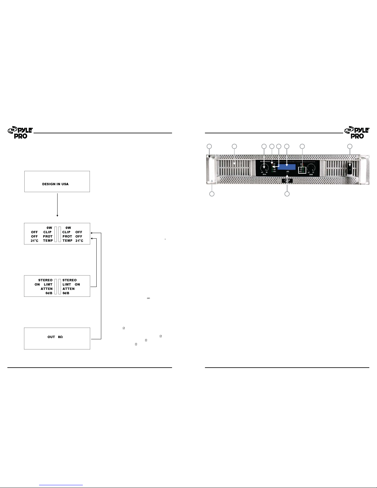
Second Screen
Third Screen
Fourth Screen
Andthen display:
displaysLeft and Right channel
outputsPOWR(0W), displays Left and
Rightchannel CLIP(ON/OFF),
displaysLeft and Right channel
PROT(ON/OFF),displaysLeft and
Rightchannel heat sink TEMP(oC)
anddisplays left and right channel
outputlevel meters, you can view the
valuesof the output signal and view
howmany power output.
Ifstereo/bridge switch or limiter switch
orpotentiometer action, and then you
canview this screen, you can view
stereo/bridgeworking mode and
limiterswitch set position ,and shows
leftand right channel output
attenuationhistogram, and read the
valueof the output attenuation,output
attenuationrange from - to 0dB.After
afew seconds return to second screen .
Press4/8 tact switch ,you can view
thisscreen, after a few seconds return
tosecond screen.If you select 8 the
outputpower value is 8 ,else show
outputpower is 4 .
Page 6
Graphic LCD Display Screen Explain
First Screen
OpeningScreen: On power-up,the
LCDControl Screen displays the
"PYLEPRO...".After a few
seconds,thenthe "Second Interface"WorkingStatus screen appears.
PEXA SERIES
PYLE PRO
Front Panel
1
9
2 3 6
10
4 5 7 8
1.Rack Mounting Ears
2.Fan Outlet Grill
3.Channel Level attenuators
4.Protect LEDS
5.CLIP LEDS:
6.Graphic LCD display:
7.LEVEL LEDS
8.Power switch
9.Optional Rack Handles.
Two front-panel mounting holes are provided on each mounting ear.
Series amplifiers are cooled by fan.Cool air flows over the heat sink and exhausts
through the front grill.Make sure this outlet remains clear to allow unrestricted airflow.
Two input attenuators adjust level for their respective amplifier channels. In Bridged Mono
modes, the channel A attenuator controls overall signal level (see rear panel mode switch
description).
This Red LED indicates that the amp channel is in Protect mode.During Power up, the amp
briefly goes into protect mode in order to prevent any loud speakers from being fed the
speakers. After a few seconds the amp comes out of protect mode and is ready for normal
operation. If the amp stays in Protect mode, this indicates that there may be a problem internal
to the amp. If the amp goes into Protect mode during operation this indicates that either a
problem has developed internal to the amp or the amp is being over-stressed and needs to
cool down. After a Protect condition, the amp must be reset by cycling the power off and then
on again in order to continue using it.
When the output power exceeds the safe working range of the amplifier,the CLIP LED are lit.
LCD display as: Company name/logo, detailed power at 2ohm/4ohm/8ohm,Limiter,Working
mode, Protection(L/R), Level(L/R), Temperature(L/R heatsink), Clip(L/R), Gain(L/R),Detail
wiring diagram you can refer to .
SIGNAL LEDS inintensity inresponse to signals up to -30dB.-20dB to -10dB LEDS indicate
output levels.
This switch turns the amp on and off.
Availablefrom your authorized Crest Audio supplier.
PEXA
Graphic LCD Display Screen Explain
Page 3
PEXA SERIES
Page 5
10.Loaded Select.
Press4/8 tact switch ,you can view this screen, after a few seconds return to second screen.If
youselect 8 the output power value is 8 ,else show output power is 4 .
11.XLRBalanced Input Connectors
13. Output Mode Selector Switch
EachChannel features balanced XLR and 1/4" jack sockets wired in parallel. The Balanced
signalsare less sensitive to hum noise generated by AC.
Thestereo power amplifier presents two operating modes:
-Stereo Mode
Inthis mode, channel A and channel B operate independently (as a normal stereo amplifier). The
ChannelAinput signal will be output from the channel A output connector,and channel B input
signalwill be output from the channel B output connector.
-Parallel Mono Mode
Inthis mode, channel A input signal will be output from the output connectors of both channels.
12.LIMITER Switch
Ifa very high level signal is driven into the amplifier, the output signal will "CLIP", that is the peaks
ofthe waveform will be flattered. The Clip Limiter circuit automatically reduces the gain to prevent
theoverdrive. Youcan switch the Clip Limiter circuit ON and OFF via the (11)switch on the rear
panelof your LA series. If you use full range speakers, the Clip Limiter circuit will reduce the high
frequencydistortion and it will also protect the high frequency drivers. However, some Users
preferto switch the Limiter OFF to get more punch from Kick Drums and other sounds in the low
frequenciesarea.
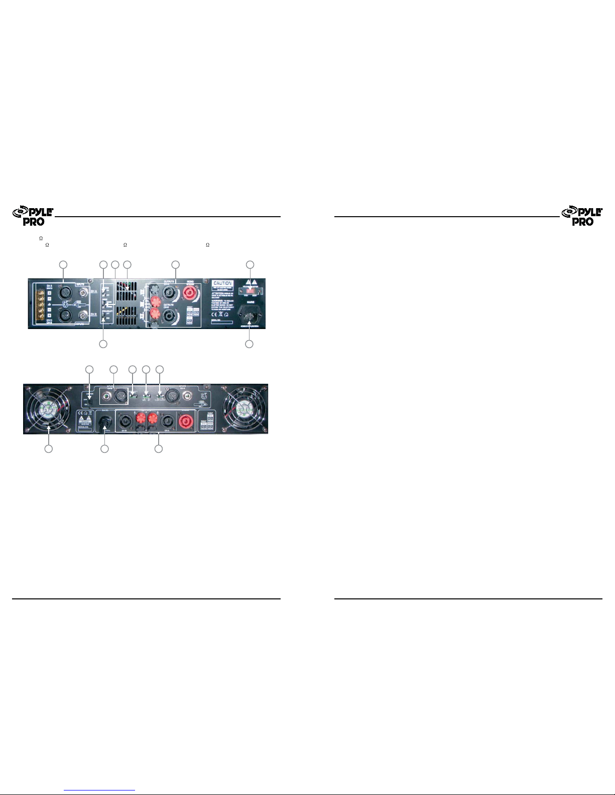
PEXA3000,PEXA5000 Rear Panel
Page 5Page 4
18
11 1512 1413
17
16
PEXA SERIESPEXA SERIES
-Bridged Mode
Inthis mode, channel A input signal will be output from the bridge-mono output Connector.
Thisfan secures enough cooling for your PEXA3000,PEXA5000 amplifier.
SPEAKONconnectors are specifically designed to connect high power speakers. The correct
polarityis secured automatically, they prevent shock hazard and they lock-in securely.
Pleasemake sure to respect the speaker polarity when using binding post.
Caution:turnoff the unit before connecting an audio signal to the binding post to avoid any electric
shock!
Pleasemake sure that your local voltage matches the voltage indicated on the unit.
SignalGround lift switch is used to lift the balanced input connectors'ground/shield from the
amplifier'sground. When the signal ground lifted, the sound source disconnects from the
amplifier'sground preventing ground loops which can generate hum and noise. See the signal
groundlift switch instructions for more detail.
Thepower amplifier must be connected only with the attached three-wire safety power cord with
protectiveconductor (nonfused earthed conductor).
Thisamplifier is made for use with te mains voltage labelled on the back of the amplifier only.
Checkthe label on the back panel of the amplifier for the appropriate voltage. Make sure the
voltageof your mains outlet is correct. The power voltage is factory set as labelled on the back
paneland cannot be change afterwards. Damage caused by connecting the amplifier to
ImproperAC voltage voids the warranty.
Allowsselection of 0.775V,1.0V or 1.40V sensitivity.
Thisfan secures enough cooling for your PEXA8000 amplifier.The airflow is front-to-rear.Thefan
speedis electronically regulated depending on the temperature of the power devices.
*DOnot use these amplifiers in damp or high humidity environments. Do not use outdoors or
anywherewhere liquids could fall or splash onto the amplifier.
*Ensurethe amp is adequately ventilated, with free airflow to the front and rear panels. Keep
awayfrom other heat sources. If the amps are mounted in a rack with other amps, ensure there is
adequatecool air flow front and rear. Note that air is drawn in through the back panel, and
exhaustedthrough the front panel.
*Nevercover the amplifiers, as they may overheat.
*PYLEPRO power amplifiers are designed to fit standard 19U racks, with a 2U height and 17
depth.We recommend the use of rear rack supports, especially if the rack is to be mobile. Use
shakeproof washers or thread lock adhesive to prevent mounting bolts becoming loose in transit.
*Ensurethat the AC power supply is correct for your amplifier. The required AC supply is stated
onthe rear panel next to the AC power input.
*Ensurethat you use the correct type of mains lead for your equipment and country. This must be
freefrom damage and easily accessible during use.
14.Cooling Fan Window
15.SPEAKONAnd BINDING POST Outputs
16.VoltageSelector
17. Signal Ground Lift Switch.
18.Power Connection
19.SENSITIVITYSelector Switch
20.Cooling Fan
Installation guidelines
20
12 11 17 1913
18 15
PEXA8000 Rear Panel
 Loading...