

R
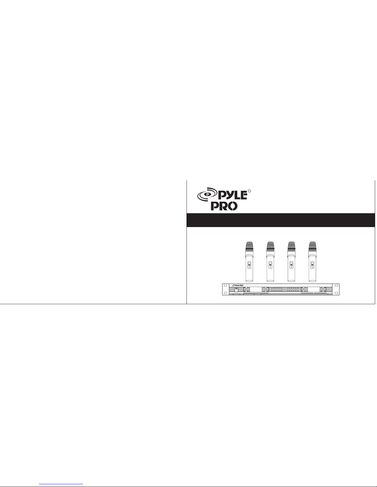
PDWM5500
OPERATING INSTRUCTIONS
WIR ELESS M ICROP HONE SY S TEM
POWER
PWMA5 00 0 P ROF ES SI ON AL W IR EL ES S M ICR OP HO NE SY STE M

..... ....S PECIF IC ATIO N.. .. ... ..
1) Carrier Frequency:.................... VHF 160-280MHz
2) Frequency Stability:.....................0.005%
3) Modulation mode:.....................VHF
4) Audio Frequency Response:................60Hz-16KHz
5) Signal to Noise Ratio:...................>60dB
6) Maximum Sound Pressure Level:..............>100dB
7) Distortion:........................<0.5%
8) Operating Range:.....................Approx 240 ft.
Sys tem Spe cific ation s
1) RF Output Power: .....100mW MAX
2) Harmonic Suppression:...................40dB
3) Antenna:.........................Builtin
4) Power Supply:.......................1.5V(AA) x3
5) Nominal Current Drain:...................Approx. 15mA
6) Battery Life:........................Approx. 12 hours
................
Tran smitt er
1) Receive Mode:......................Crystal Frequency Lock
2) Sensitiity:.........................40dBu(S/N=60dB)
3) SignaltoNoise Ratio:....................>60dB
4) Audio Output Level:....................400mV Max
5) Power Supply:.......................AC110V/220V(.10%) DC12v-18v/500mA
Rec eiver
- 4 -
Thank you for selecting the PDWM5500 4 Mic VHF Wireless System. Before operating please read this instruction manual carefully
and thoroughly in order to understand the correct operating procedures and achieve the best results.
1) Plug the included audio cable into the receiver's mixed output connector, and the other end into a mixer or power amplifier system.
Extend the two antennas fully to the vertical position. Switch on the receiver. The POWER ON light will illuminate.
2) Open the battery cover of the microphone and install the batteries inside the compartment properly. Replace the cover.
3) Position the transmitter power switch to ON. The indicator light will illuminate. The microphone features a 3-way power switch. The
middle position (standby) functions as a mute switch.
4) The receiver's corresponding channel light will illuminate, indicating reception.
5) Adjust the volume knobs of the receiver and power amplifier.
6) When the transmitter power indicator dims, it indicates low battery power. Replace the batteries.
- 1 -
..... ..... .PREFA CE ... .. ... .. .
FEAT URES:
SYS TEM SET UP
ALC circuit to eliminate distortion:
Frequency compressing/expanding (companding) circuitry to lower noise and increase the dynamic range.
Superior squelch and high signal to noise ration.
Near zero noise output when on standby.
Wide frequency response range and low distortion.
Convenient operation status indicators.
LED Displays.
Multiple HF and MF narrowband filters to eliminate interfering signal.
Low power consumption components to ensure longer battery life.
Special impact wave eliminating circuit for microphone switch.
Long transmitting distance-up to 240 ft. in ideal circumstances.
 Loading...