

R
PDWM5000
OWNER S MANUAL
PROF ESSION AL SERIES W IRELESS M ICROPH ONE SYST EM
R
Py le Au di o. co m
71 8. 53 5. 180 0 71 8. 23 6. 24 00 (f ax )
16 00 63 rd S tr ee t, B roo kl yn N Y 11 204
.........SP ECI FIC ATION........ .
1) Frequency Range:...... .............. VHF 160-280MHz
2) Fre que ncy Sta bil ity :.. ... ... ... ... ... ... .. ..0 .00 5%
3 ) Mo d ul at io n m od e: .. .. .. .. .. .. .. .. .. .. .. .. .. VH F
4) Mod ula tio n De via tio n:. ... ... ... ... ... ... ... .20 KHz
5) Audio Frequency Response:...................40Hz-20KHz
6) S ign alt oNo is e R ati o: ... ... ... .. ... ... ... .. ..> 60d B
7) Maximum Sound Pressure Level:..................>100dB
8 ) D i st o r ti o n: . . .. . .. . .. . . .. . .. . . .. . .. . .. . . .0 . 5%
9) Operating Range:................80m (under typical conditions)
10) Operation Temperature Range:.................10.~+50.
Sys tem Spe citic ation s
1) RF Out put Po wer: ...... ..100mW MAX
2) Ha rmon ic Su ppre ssio n:.. .... .... .... .... .... ..40 dB
3 ) A nt e nn a :. . .. . .. . .. . .. . .. . .. . .. .. . .. . .. B ui l ti n
4) Pow er R equireme nt:..... ........ ........ ...9V Ba ttery
5) Nominal Current Drain:..................Approximately 15mA
6) B att er y Li fe :.. .. ... .. ... .. ... .. ... ... .. .12 h ou rs
...... ..........
Tran smitt er
1) Receive Mode:....................Crystal Frequency Lock
2) S ensit iity: ..... ...... ..... ..... ....4 0dBu( S/N=6 0dB)
3) S ignal toNoi se R atio: ..... ..... ..... ..... .....> 60dB
4) Audio Output Level:....................0~400mV Max
5) Power Supply:.....................AC110V/220V(.10%)
6) Dimension:.............. .......WxDxH=485x240x52mm
Tran smitt er
- 4 -
Thank you for buying our excellent wireless microphone series products. Before you use our products, please read this Owner's
manual for vour corrective operation, Please keep this manual in a safety place for your future reference.
VHF series professional wireless microphone systems introducesa number of advanced techniques and components, including
the efficient lowconsumption RF transmission, impact elimination, slowcontrolled output, superiorssensitivity VHF narrowband HF
and MF filters and 15ppm Crystal Frequency Lock etc. Online simulation EDA and strict quality control are applied to ensure
each system withexcellent function.
Introducing a special ALC circuit to ensure nondistortion;
lntroducing frequency compressingexpanding technique to lower the
noise and enlarge the dynamic range.
Superior squelch and high signaltonoise ratio.
Aimost zero noise output when standby.
Broad frequency response range, super low distortion.
Perfect operation status indications.
1) Plug the provided audio cable into the receiver's ALL output connector, and the other end into a mixer or power amplifier system.
Extend the two antennas fully to the vertical position.Switch on the receiver, the POWER ON light will glow indicating the machine
standby. (Better keep distances between the receiver and floor to ensure good receiving signals).
2) Open the battery cover of microphone and install the batteries inside the compartment properly, then replace the cover.
3) Position the transmitter power switch to ON, indicator light will glow (wid position is MUTE ). Now the receiver's corresponding
.
channel light will also glow, indicating that the receiver has already received the effective signals from the transmitter. Adjust the
volume knobs of the receiver and power amplifier to ensure the suitable volume for the system. Speak with microphone to check the sound.
4) When the transmitter power indicator dardens, it indicates low battery power. Please change with new batterles in time. (Note to not
mix new and old batteries together)
5) When using multiple systems at the same time, it is necessary to use machines of different frequency.
System Tumon Process: Receiver .Mixer or Pre Amplifier .Power Amplifier (Opposite when Tumoff)
- 1 -
........... PRE FACE ... ... ... ..
FEAT URES:
SYS TEM SET UP
Introducing multiple HF and MF narrowband filters to eliminate
interfering signal.
Introducing low power consumption components to ensure the longer
battery life.
Special impact wave eliminating circuit for handheld microphone switches.
Long practical distance. Over 80m in ideal circumstances; practiacal
20m radius incomplex circumstances;
Multiple frequency design. Be able to use two microphones at the
same time withoutmutual interference;
Applicable for medium & small stages, karaoke halls, and home
entertainment etc.
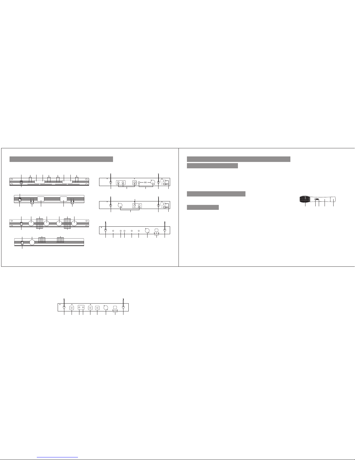
1) Power lndicator;
2) Power Switch;
3) CH. A Volume Control;
4) CH. A Receiving lndicator;
5) CH. B Receiving lndicator;
6) CH. B Volume Control;
1) Cartridge Grille;
2) LED Power lndicator.;
3) Power Switch; 4) Mic Body;
5) Battery Compartment
1) Read Carefully: Read all safety and operat ion directio n carefully befor e using this product.
2) Keep the Manua: Keep this Owner's Manual in a safety place for future referen ce.
3) Mind the Cautions: Please follow all the cautio ns indicated on the machine or in the manual.
4) Follow the lnstruction: Plea se follow all the operatio n process and operatio n instructio n.
5) Safety Environment: Don't put the machine in the place of high humidity, high electro magnetic field strong sun light and high temperature.
6) Attention when Stop Using: When stop using for a long time, please unpug the AC cord and remove the mic batteries.
7) Cleaning: Before cleani ng, please turn off the system power. Don't clean it with liquid or sprayer. It is suitable to use wet cloth.
8) Accessories: Only use the provided access ories or other certifi cated products.
9) Power supply: The machine is only applicable to the indica ted power supply. Please confirm wheth er it is suitable for your district.
10) Main taining: To avoid the risk of el ectric shock, do n't open or remove the co ver to repair the mac hine by yourself . Ask a qualif ied
repairman to repair it.
11) Replacing Componen ts: Before replace any componen, the repair man should check carefully to confirm wheth er the machine is in
safe position.
12) Adjustment: When the machine is broken down, to avoid the great damages, don't adjust any adjustable component by yourself. You
should ask an expert to repair it. Or you can also contact with the dealer and we will try all our best to help you.
ON
(1) (2) (3) (4) (5)
- 3 -
.....RECEIV ER AND TR ANSMITTER.. ...
POS ITION S KETCH O F RECEI VER
POS ITION S KETCH O F TRANS MITTE R
SAF ETY DIR ECTIO N
7) CH. C Volume Control;
8) CH. C Receiving lndivator;
9) CH. D Receiving lndicator;
10) CH. D Volume Control;
11) CH. B Antenna Connector;
12) lndividual Audio Output;
13) Mixed Audio Output;
14) CH. A/B Antenna Connector;
15) AC Power lnput (voltage selectable);
16) CH. A Antenna Connector;
17) CH. C/D Antenna Connector.
REAR PAN EL OF RECEIV ER
17 12
13
14
15
11
13 16 15
12
FRON T PANEL OF R ECEIV ER
1 3 4 5 6 7 8 9 10
2
POWER
PWMA5000 PR OFE SSI ONA L WI REL ESS M ICR OPH ONE SYS TEM
DOWN UP CHA CHA DOWN UP DOWN UP CHA CHA DOWN U P
1
2 3 4 5 6
POWER
1
2
3
4 6 7 8 10
PWMA2000 PR OFE SSI ONA L WI REL ESS M ICR OPH ONE SYS TEM
POWER
C A VOLUM EH C VOLUMEHB C VOLUMEHC C VOLUMEHD
9
1
2
3
4 4
POWER
C A VOLUM EH
PWMA2000 PR OFE SSI ONA L WI REL ESS M ICR OPH ONE SYS TEM
- 2 -
.....RECEIV ER AND TR ANSMITTER.. ...
OUT D
OUT C
ANT.CD
OUT B
DC13V/50 0mA
++
ANT.AB
MIX OUT OUT A BALACEDN
OUT D
OUT C
ANT.C&D
OUT B
DC13V/50 0mA
++
ANT.C&D
MIX OUT OUT A BALNACED
 Loading...