

Page 1

Specifications
PYD2200
Input Sensitivity/Impedance
Mic 1-2
Phono 1-2
Line 1-9
Output Level
Amp
Booth
Record
Frequency Response
S/N Ratio (at 1 kHz)
Mic
Phono
Line
Distortion
Mic
Phono
Line
Limited Warranty
All PYLE PRO products are carefully constructed and tested before shipment.
Units purchased in the USA are warranted to be free of defects in material
and workmanship for two (2) years from the date of purchase. This warranty
is limited to the original retail purchaser of the mixer.
Should the unit fail due to factory defects in material or workmanship, your
unit will be repaired or replaced at the sole discretion of PYLE.
To obtain warranty service, you must first call our Consumer Return Hotline
at (718) 236-6948 to obtain a Return Authorization Number. This R.A. # must
appear on the outside of your package and on all paperwork relating to your
return.
When returning the unit to us for warranty service, it must be carefully
packed and shipped, prepaid, to:
Please complete warranty card, detach and return
Thank you for purchasing this PYLE
product. To activate your
warranty, please mail this card
within 10 days.
1.5 mV/600 Ohms, bal/unbal
3.0 mV/50K Ohms
150 mV/27K Ohms
2.0 V/10kOhms
2.0 V/10kOhms
150mV/10kOhms
20Hz – 20kHz +/- 3 dB
>60 dB/1.5mV input
>70 dB/3.0mV input
>80 dB/150 mV input
0.20%
0.05%
0.03%
warranty registration card
High
Mid
Low
MIC Tone Control
High
LOW
Talkover Attenuation
Power Source
Dimensions, inches
(mm)
R.A.#: _____________
PYLE PRO Service Center
1600 63rd Street
Brooklyn, NY 11204
You must also include the following items with your return:
• A copy of your sales receipt or other proof of purchase
• A brief letter, indicating the problem you are experiencing with the product
• Include in your letter your return address, daytime phone number and R.A. number
• Also include a check or money order for $18.00 for return
shipping, handling and insurance, or provide your Visa/MC number with expiration date.
Our obligation under this warranty is limited to the repair or replacement
of the defective unit when it is returned to us prepaid. This warranty will
be considered void if the unit was tampered with, improperly serviced or
subject to misuse, neglect or accidental damage.
10kHz; +12/-12dB
1 kHz; +12/-12dB
100Hz; +12/-12dB
10kHz; +10/-10dB
100Hz; +10/-10dB
-16dB
120 VAC, 60Hz/230 VAC, 50 Hz
19.0 x 4 x 7
(482 x 101.6 x 177.8)
PYD 2200
5 channel
professional
mixer
Name
Address
City, State ZIP
Model No. Serial #
Date of Purchase
Purchased at:
Music Products Store
Catalog Merchandiser
PYLE PRO MIXERS
Sound Contractor/Installer Mail Order
Other
(if available)
pro series
www.pyleaudio.com
9 – Pyle Pro Mixer Owner’s Manual
Page 2

Your PYLE PRO Series Performance Mixer
is a sophisticated control center, perfect for mixing sound from multiple playback sources such as
microphones, tuners, CD players, turntables or the audio outputs from a VCR. This mixer is ruggedly
constructed for home or professional use. Wide range volume controls permit you to adjust sound levels
accurately to achieve just the right mix for playing through your speaker system or for recording.
Please read this manual thoroughly before you attempt to set up and use the mixer. It contains a
range of suggestions and instructions to insure safe usage. Set up and used properly, you can expect
years of trouble-free service from this product.
Owner’s Manual Table of Contents
i
Input/Output Features
1
Features and Controls: PYD 2200
2
Presetting Controls Before Use
Connecting the Mixer Inputs
4
Using the Gain Controls
Connecting the Mixer’s Outputs
to Amplifiers
to Recorders
to Booth Speakers
5
Using Headphones
6
Using the Mixer Controls
Turning On the Mixer
Monitoring (”Cueing”) Inputs
Mixing Inputs
7
Adding Equalization to the Mix
Using the MicrophoneTalkover Mode
Microphone Tone and Level Controls
Using the Crossfader w/Assign Switches
8
Troubleshooting
Care and Maintenance
9
Specifications
Warranty
Input/Output Features:
Stereo Line Inputs let you connect
most high-level audio sources, such as
CD players, tape deck, tuner or VCR.
VOLTAG E
~AC IN PU T
FUSE F 50 0m A 25 0V
Output Jacks to connect the mixer to a
receiver or amplifier – choose to use cables
with either 1/4” plugs or RCA plugs.
Booth Output Jacks to connect the mixer
to a second receiver or amplifier powering
speakers in the DJ booth or in a remote
location
Record Output Jacks to connect the
mixer to a tape deck for recording the
mixed program
OUTPUT
BALANCED
Master Booth Rec
L
LR
R
CH 5 CH 4 CH 3 CH 2 CH 1
L
L
R
R
Line 9 Line 8 Line 7 Line 6 Line 5Line 5 Phono 2
Dual Purpose Stereo Inputs for
using a turntable with a magnetic
cartridge OR a high level input
source
Input Select Switches – set these
switches based on what is plugged
into Phono1/Line2 and Phono2/Line4
input jacks
R
LN 4 PH 2 Line 3 Phono 1
/Line 4
INPUT
LRLRL
LL
R
LN 2 PH 1 Line 1
/Line 2
Ground Screw
for turntables
MIC2 Microphone
connector permits
you to connect a
balanced or
unbalanced low
impedance microphone
with 1/4” plug.
GND
MIC 2
Features and Controls: PYD2200 Mixer
MIC 1 Combo Input Jack For
connecting a balanced or unbalanced
low impedance microphone with XLRtype or 1/4” plug
MIC 1
+3
MIC 2 Line 1
0
Gain
-
5
-
10
MIC 1 Volume
MIN MAX
-10 +10
-10 +10
MIC Talkover Allows you to lower the
level of the input sources so you can talk
them using the DJ Mic
MIC1 Tone Controls
MIC1 Level Controls Lets you control the
MIC levels as they enter the mix
MIN MAX
-
15
Cue Cue Cue Cue Cue
High
High
-10 +10
Low
Mid
-10 +10
Low
TALKOVER
ON
-10 +10
OFF
CH 3
CH 2
CH 1
ASSIGN A ASSIGN B
Phono 1
+3
Line 2
0
-
5
-
10
-
15
High
10
CH
9
-10 +10
8
Mid
7
6
5
1
4
-10 +10
3
Low
2
1
0
-10 +10
CH 4
CH 5
MIN MAX
Gain
2
+3
Line 3
0
-
5
-
10
-
15
10
CH
9
-10 +10
8
7
6
5
4
-10 +10
3
2
1
0
-10 +10
CROSSFADER
Phono 2
+3
Line 5
Line 4
0
Gain
-
5
-
10
MIN MAX
-
3
15
High
10
CH
9
-10 +10
8
Mid
7
6
5
4
-10 +10
3
Low
2
1
0
-10 +10
High
Mid
Low
+3
Line 7 Line 9
Line 6 Line 8
0
Gain
-
5
-
10
MIN MAX
-
15
High
10
CH
9
-10 +10
8
Mid
7
6
5
4
4
-10 +10
3
Low
2
1
0
-10 +10
CH 3
CH 4
CH 2
CH 1
CH 5
Channel Gain Control Lets you adjust the gain of the input source
Channel Input Selector Lets you choose the input source to play
for each channel
Channel CUE Switch Allows you to monitor the selected audio
input source and prepare it prior to mixing it in.
Dual VU Meter Indicates the levels of Left and Right Master Channels
Gain
MIN MAX
Headphone CUE/PGMControl Allows you to listen simultaneously
or separately to the CUE material or the active program
3-Band Equalizer Allows you to tailor the mixer output to suit your
taste or performance environment. Each frequency range can be
cut or boost by up to 12dB.
Crossfader Slider Control Allows you to smoothly switch between
the input sources assigned to Channel A and Channel B
Channel Level Slider Control
Channel Assign Switch Lets you select the input source to be
mixed by the Crossfade Slider Control
5
+6
+3
0
-
5
-
10
10
CH
9
-
15
8
7
-
20
6
5
-
25
4
3
-
30
2
1
PWR
0
CUE PGM
POWER
Balance
+6
+3
Master Balance Control
0
LR
Master
-
5
Master Level Control
-
10
Headphones
-
15
-
20
-
25
-
30
PWR
Lets you control mixer’s
overall volume level
Booth Level Control Lets
you control the mixer’s
overall BOOTH volume level,
if you set up remote speakers
or DJ booth monitors
Headphone Level Control
Headphone Jack
Accepts headphones with
1/4” plug
010
Booth
010
Cue Level
010
Mix
Pyle Pro Mixer Owner’s Manual – 1i – Pyle Pro Mixer Owner’s Manual
Page 3
LL
R
L
R
L
R
PH 2 Line 3 Phono 1
/Line 2
LN 2 PH 1 Line 1
CH 2 CH
NPUT
LL
R
L
R
L
R
PH 2 Line 3 Phono 1
/Line 2
LN 2 PH 1 Line 1
CH 2 CH
NPUT
Presetting the Controls Before Use
Since sudden high output levels from your Pyle Pro mixer can damage not only audio devices connected
to the mixer output but your hearing as well (especially if you are using headphones), please adjust
the mixer’s controls BEFORE connecting AC power or turning on the unit.
Set up the mixer controls like this before you start:
CONTROL SETTING
Power On/Off
Balance
Gain
Tone Controls, High, Mid & Low
MIC 1, CH 1/2/3/4/5, Master & Cue Levels
Crossfader
Connecting the Mixer Inputs
This mixer permits connection of up to nine (9) audio input sources,and two microphones. Such a
system might include, for example:
Two Microphones
Two Turntables
Seven CD players
Please observe
the following:
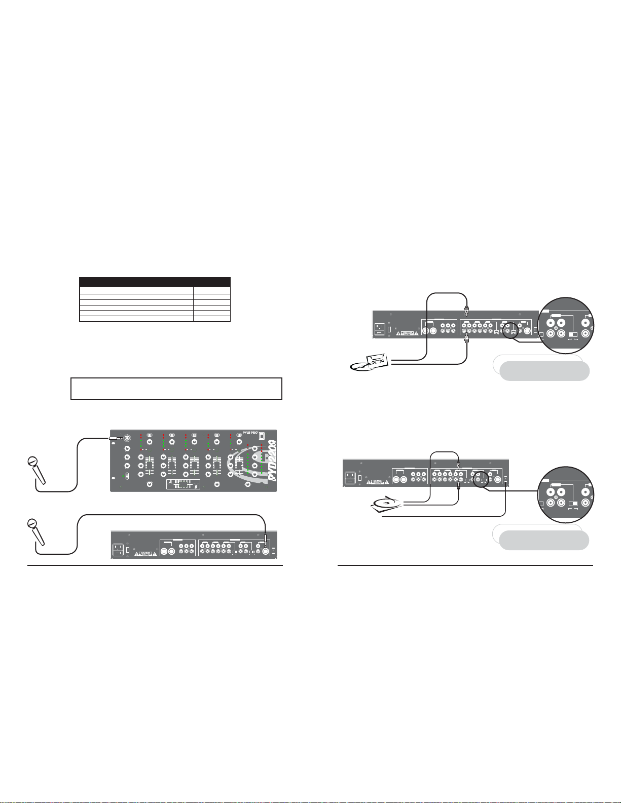
Connecting Microphones
Microphone 1. Connect a balanced/unbalanced low impedance (600 Ohm) XLR type MIC OR a low
impedance MIC with a 1/4” plug to the MIC 1 jack in the upper left corner of the mixer control panel.
MIC 1
Microphone 2. Connect a high quality balanced/unbalanced low impedance (600 Ohm) microphone
with a 1/4” plug to the MIC 2 jack on the lower left corner of the mixer’s back panel.
Two Microphones
Nine CD players
Do not connect any audio source with a HIGH LEVEL OUTPUT to the
LOW LEVEL PHONO 1 or PHONO 2 mixer audio input jacks (an audio
source output with a volume control is HIGH LEVEL).
Use 1/4” or
XLR-type jack
Two Microphones
Two Turntables
Four CD players
Three Cassette Decks
MIC 1
MIC 1 Volume
MIN MAX
High
-10 +10
Low
-10 +10
TALKOVER
ON
OFF
+3
+3
MIC 2 Line 1
0
0
Gain
-
5
-
5
-
10
-
10
MIN MAX
-
15
-
15
Cue Cue Cue Cue Cue
High
High
10
CH
9
-10 +10
-10 +10
8
Mid
Mid
7
6
5
1
4
-10 +10
-10 +10
3
Low
Low
2
1
0
-10 +10
-10 +10
CH 3
CH 4
CH 2
CH 1
CH 5
ASSIGN A ASSIGN B
MIC 2
VOLTAGE
~ACIN PU T
FUSE F 5 00m A 25 0V
BALANCED
OFF
MID
MID
0
0
CENTER
Two Microphones
Two Turntables
Four CD players
One Rhythm Synth
Two Cassette Deck
Phono 1
Phono 2
+3
Line 3
Line 2
Line 4
0
Gain
Gain
-
5
-
10
MIN MAX
MIN MAX
-
15
High
10
CH
9
-10 +10
8
Mid
7
6
5
3CH4
2
4
-10 +10
3
Low
2
1
0
-10 +10
CROSSFADER
OUTPUT
Master Booth Rec
L
L
LR
R
R
+3
+3
Line 5
Line 7 Line 9
Line 6 Line 8
0
0
Gain
Gain
-
5
-
5
-
10
-
10
MIN MAX
MIN MAX
-
15
-
15
High
High
10
10
CH
9
9
-10 +10
-10 +10
8
8
Mid
Mid
7
7
6
6
5
5
4
-10 +10
3
Low
2
1
0
-10 +10
CH 5 CH 4 CH 3 CH 2 CH 1
L
R
Line 9 Line 8 Line 7 Line 6 Line 5Line 5 Phono 2
5
4
-10 +10
3
Low
2
1
0
-10 +10
CH 3
CH 4
CH 2
CH 1
CH 5
Use 1/4”
jack
INPUT
R
LN 4 PH 2 Line 3 Phono 1
/Line 4
10
CH
9
8
7
6
5
4
3
2
1
0
CUE PGM
/Line 2
POWER
Balance
+6
+6
+3
+3
0
0
LR
Master
-
5
-
5
-
10
-
10
010
-
15
-
15
Booth
-
20
-
20
-
25
-
25
010
-
30
-
30
Cue Level
PWR
PWR
010
Mix
Headphones
GND
LRLRL
LL
MIC 2
R
LN 2 PH 1 Line 1
Connecting High Level Output Audio Sources
Connect up to 9 such sources (tuner, cassette deck, CD Player, camcorder or VCR) to the input jacks
for Line 1 , Line 2(if not being used as Phono 1 input), Line 3, Line 4(if not being used as Phono 2
input), Line 5, Line 6, Line 7, Line 8 and Line 9. Please note that Phono 1 and Line 2 (as well as
Phono 2 and Line 4) use the same jacks. The selector switch(e)s below the jacks should be set to
Line position if the jacks are used for the High Level input sources described here.
Use RCA type
patch cables
VOLTAGE
~ACIN PU T
FUSE F 5 00m A 25 0V
High Level Output
Audio Source
CD player, cassette deck, camcorder, VCR, etc.
LEFT output
RIGHT output
OUTPUT
BALANCED
Master Booth Rec
L
L
L
LR
R
R
R
Line 9 Line 8 Line 7 Line 6 Line 5Line 5 Phono 2
INPUT
CH 5 CH 4 CH 3 CH 2 CH 1
LRLRL
R
LN 4 PH 2 Line 3 Phono 1
LN 2 PH 1 Line 1
/Line 4
/Line 2
NOTE!
If you use a High Level Output Audio Source(s)
in the Phono1/Line2 (and/or Phono2/Line4)
input jack(s), be sure to place the Input Select
switch in the LINE2 (and/or LINE4) position(s)!
GND
LL
MIC 2
R
Connecting Turntables and Other Level Output Audio Sources
Connect up to 2 turntables to the Phono 1 and Phono 2 input jacks. Please note that Phone 1 and
Line 2 (as well as Phono 2 and Line 4) use the same jacks. The selector switch below the jacks should
be set to Phono position if the jacks are used for phono inputs.
When using a turntable, you should also securely connect its ground wire (usually green or black)
to the Ground screw on the input panel of the mixer.
Use RCA type
patch cables
VOLTAGE
~ACIN PU T
FUSE F 5 00m A 25 0V
Magnetic cartridge turntable
OUTPUT
BALANCED
Master Booth Rec
L
L
LR
R
R
LEFT output
RIGHT output
GROUND wire from turntable
L
R
Line 9 Line 8 Line 7 Line 6 Line 5Line 5 Phono 2
/Line 4
R
LN 4 PH 2 Line 3 Phono 1
/Line 2
INPUT
CH 5 CH 4 CH 3 CH 2 CH 1
GND
LRLRL
LL
MIC 2
R
LN 2 PH 1 Line 1
NOTE!
If you use a Turntable in the Phono1/Line2
(and/or Phono2/Line4) input jack(s), be sure
to place the Input Select switch in the PHONO1
(and/or PHONO2) position(s)!
Pyle Pro Mixer Owner’s Manual – 32 – Pyle Pro Mixer Owner’s Manual
Page 4
Using the Channel Input Gain Controls
Adjusting the Gain controls for each channel permits you to fine tune the level of each of the audio
inputs, since input levels usually vary. Rotate the Gain controls clockwise to increase levels. After
you preset the gain levels for each input, it is recommended that you do not adjust them further,
as you can cause sound level imbalances during a mix.
Connecting the Mixer Outputs
Output to an Amplifier
To play the mixer’s output signal through your speaker system (for events such as parties, dances,
conferences, etc.) connect an audio patch cord (not supplied) from the mixers AMP L and R jacks
to your receiver amplifier’s left and right input jacks.
This mixer features two kinds of output jacks for you to choose from: RCA style and 1/4” type. DO
NOT USE BOTH SIMULTANEOUSLY.
Output to a Tape or Digital Audio Recorder
To play the mixer’s output signal through your speaker system (for events such as parties, dances,
conferences, etc.) connect an audio patch cord (not supplied) from the mixers REC L and R jacks
to your receiver/amplifier’s left and right input jacks.
Booth Output
To monitor the mixer output to a second set of speakers in the DJ booth (or in a remote location)
connect an audio patch cord (not supplied) from the mixers BOOTH L and R jacks to your secondary
amplifier’s left and right input jacks.
CAUTION: In order to avoid sudden unpleasant sound output,
adjust the output devices controls to these settings before you
connect the mixer’s output jacks to these devices’ input jacks.
OUTPUT DEVICE SETTINGCONTROL
Tape Deck
Amplifier/Receiver
POWER
POWER
TONE
OFF
OFF
FLAT
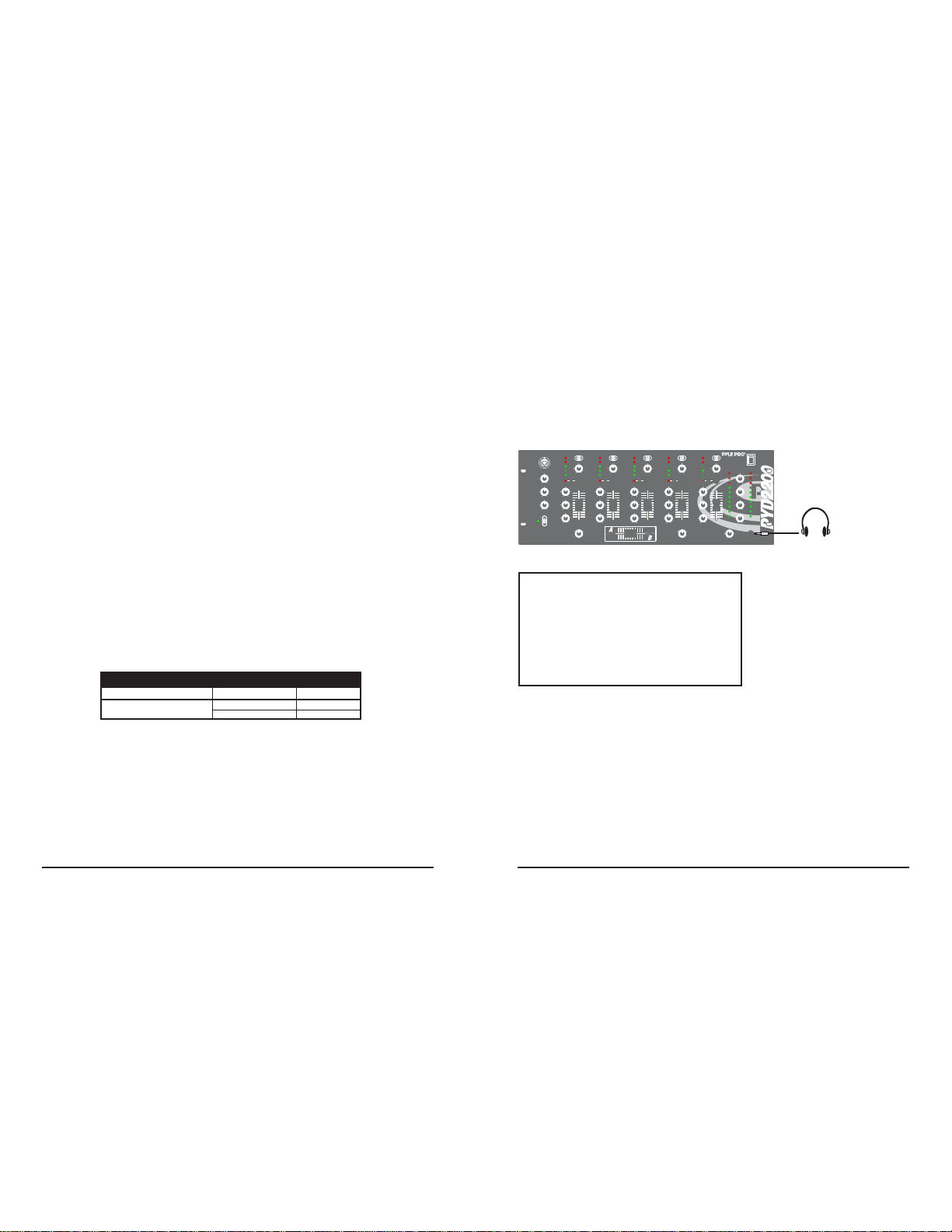
Using Headphones
Plug a pair of stereo headphones (not supplied) with a 1/4” jack into the Phones input. Using
headphones not only affords you the opportunity to listen privately, but also enables you to monitor
(”cue”) the incoming audio sources so you can locate an exact passage or section before mixing it
in. It also gives you the opportunity to set up the relative volume level of the upcoming passage
before it joins the mix.
Phono 1
MIC 1
+3
MIC 2 Line 1
0
Gain
-
5
-
10
MIC 1 Volume
MIN MAX
-
15
Cue Cue Cue Cue Cue
MIN MAX
High
High
10
CH
9
-10 +10
-10 +10
-10 +10
8
Low
Mid
7
6
5
1
4
-10 +10
3
Low
2
1
0
TALKOVER
ON
-10 +10
OFF
CH 3
CH 4
CH 2
CH 1
CH 5
ASSIGN A ASSIGN B
Listen Safely! Please observe the following:
Do not listen at extremely high volume levels. Extended,
high-volume listening can lead to permanent hearing loss.
Follow these guidelines to protect your hearing, especially
when using headphones.
Always start by setting the volume level to the lowest
possible level before listening.
Put headphones on, and then gradually increase the
volume as necessary.
Once you set the volume level do not increase it. Over
a period of time, your ears adapt to a volume level and there
is a temptation to increase it. Even though such an increase
may not cause discomfort, it might still damage your hearing.
Phono 2
+3
+3
Line 3
Line 2
0
-
5
-
10
-
15
High
-10 +10
Mid
-10 +10
Low
-10 +10
Line 5
Line 4
0
Gain
Gain
-
5
-
10
MIN MAX
MIN MAX
-
15
High
10
CH
9
-10 +10
8
Mid
7
6
5
3CH4
2
4
-10 +10
3
Low
2
1
0
-10 +10
CROSSFADER
10
9
8
7
6
5
4
3
2
1
0
+3
Line 6 Line 8
0
Gain
-
5
-
10
MIN MAX
-
15
High
-10 +10
Mid
-10 +10
Low
-10 +10
CH 3
CH 2
CH 1
+3
Line 7 Line 9
0
-
5
-
10
MIN MAX
-
15
High
10
CH
9
-10 +10
8
Mid
7
6
5
4
-10 +10
3
Low
2
1
0
-10 +10
CH 4
CH 5
Gain
POWER
Balance
+6
+6
+3
+3
0
0
LR
Master
-
5
-
5
-
10
-
10
10
CH
9
010
-
15
-
15
8
Booth
7
-
20
-
20
6
5
5
-
25
-
25
4
010
3
-
30
-
30
Cue Level
2
1
PWR
PWR
0
010
Mix
CUE PGM
Headphones
Stereo Headphones
Pyle Pro Mixer Owner’s Manual – 54 – Pyle Pro Mixer Owner’s Manual
Page 5

Using the Mixer Controls
Turning on the Mixer
1. Turn on the output amplifier and temporarily set its volume to the minimum setting.
2. On the mixer, turn ON the power switch. The power LED will illuminate.
3. Turn on the audio input sources you wish to mix, and set them to play (or talk continuously into
the microphone).
4. To monitor the audio input sources so that you can decide when to mix in each input, see
“Monitoring
‘Cueing’ the Inputs.”
5. To mix the audio input sources so that you can play them through your amplifier system or record
them on your tape deck, see “Mixing the Inputs.”
Monitoring (”Cueing”) the Inputs
1. Set the CUE ASSIGN switch of the input source (CH1, CH2, CH3,CH4 or CH 5) you wish to
monitor.
2. Adjust the Headphone Level control to a comfortable listening level.
3. The Headphone CUE/PGM control permits you to switch easily from listening to CUE material to
the playing PROGRAM sound. You can also listen to both simultaneously by moving the Headphone
CUE/PGM control to a point midway between the two ends.
Mixing the Inputs
There are a maximum of ten input sources available at one time, including two microphone inputs.
Both microphone input sources are always available as part of the mix, if desired. Each of the four
audio channels can be linked to two different input sources, and one of these sources for each channel
is available for mixing.Turn on all the available audio sources and be sure they are providing sound
before continuing.
1. Select the Channel Input Selectors for each channel, choose the audio sources you want to mix
for each channel (i.e., choose PHONO1/LINE2 or LINE3).
2. Set the Mic and Channel Level controls all to within the 8 - 10 range.
3. Rotary the MASTER volume control toward 10 until you get an average reading of 0 on both Output
Level LED Meters. The output level displayed in the meters represents the TOTAL output from all
the channels supplying audio to the mix. NOTE: Once you set this level, we suggest you do not
change it!
4. If you add or change input sources, adjust the corresponding MIC1 or CH1, CH2, CH3, CH4 or CH5
level control(s) to maintain the average reading of 0 on the LED meters.
5. To change the overall sound level, adjust the RECEIVER/AMPLIFIER (NOT THE MIXER) volume
control to the desired volume.
Adding Equalization to the Mix
These high, mid and low 3 band equallzation controls, permit you to tailor the tone frequency of
the each channels inputs processed through themix. left in their center positions, the sound is
unaffected.
Using the Microphone
Incorporating Voice into the Mix
To blend voice from the microphones with the audio program material, first be sure the MIC/TALKOVER
switch is set to the ON position. (In this position, the MIC channel is mixed into the program like
any other audio input source.)
Then adjust the corresponding MIC level controls to increase or decrease the microphone level (this
will not affect the main volume inputs). When a microphone is not in use, set the MIC/TALKOVER
switch to OFF.
Talkover Mode
Talkover mode allows a voice to be heard clearly through the microphone by attenuating all the
other audio input sources. This mode is engaged by setting the Talkover Switch to the TALKOVER
position.
Microphone Tone Controls
These HIGH, and LOW controls, permit you to tailor the tone frequencies of the MIC inputs processed
through the mix. Left in their center positions, the sound is unaffected (”flat”).
Microphone Level Controls
The independent MIC1 controls permit you to increase or decrease the levels of these microphones
within the mix.
Using the Crossfader with the Assign Switches
For crossfading effects, you can assign any of the five channels to either A or B sides of the crossfader
mix using the Crossfader assign knobs.
When the crossfade slider is in the center position, the two assigned channels play equally. Sliding
the control towards the A position will increase the level of A and fade out B proportionally to the
distance from center. Likewise, sliding the control towards the B position will increase the level of
B and fade out A.
Pyle Pro Mixer Owner’s Manual – 76 – Pyle Pro Mixer Owner’s Manual
Page 6

Troubleshooting
Your mixer should require very little maintenance. If you have problems, refer to the chart below
for possible solutions. If you cannot solve the problem, contact a qualified technician for assistance.
PROBLEM POSSIBLE SOLUTION
Nothing works • Check the AC connection. Make sure the AC outlet is “live.”
No signal from an
audio input
source
Hum from PHONO
Hum from other
source
Feedback is
present
• Check the power connection to the rest of the system (receiver/amplifier, etc.)
• Check the control setting
• Check the connection between the mixer and the input source
• Check that the turntable’s ground wire (usually black or green) is fastened securely to the GROUND
SCREW on the mixer input panel
• Make sure there are no low level inputs connected to the LINE input jacks
• Move the microphone further away from the output speakers, or use a directional microphone
Care and
Maintenance
Your Pyle Pro Mixer is an example
of superior design and
craftsmanship. The following
suggestions will help you care for
your mixer so you can enjoy years
of use:
• Keep the mixer dry. If it gets wet,
wipe immediately.
• Use the mixer only in well-
ventilated installations.
• Handle the mixer gently and
carefully - do not drop!
• Keep the mixer away from dust
and dirt.
• Wipe occasionally with a damp
cloth to keep it looking new. Do not
use harsh chemicals, solvents or
detergents!
Please complete warranty card, detach and return
PYLE PRO Audio, Inc.
1600 63rd Street
Brooklyn, NY 11204
8 – Pyle Pro Mixer Owner’s Manual
Place
Stamp
Here
 Loading...