

Page 1

Thank you for choosing our productThank you for choosing our product
Pyle Audio
1600 63rd st , Brooklyn, NY, 11204
(718)236-8000
Warning
This product contains small items that could be a choking hazard if swallowed. Keep
these items away from young children
1.Make sure these instructions are read and completely understood before attempting
installation. If you are unsure of any part of this installation, contact a professional
installer for assistance.
2.The wall or mounting surface must be capable of supporting the combined weight of
the mount and the display; otherwise the structure must be reinforced
3.Safety gear and proper tools must be used. A minimum of two people are required
for this installation. Failure to use safety gear can result in property damage, serious
injury or death.
!
.
INSTALLATION GUIDE
Item No.:
Item No.:
TV Size Range: 32 ~55
Maximum Weight Capacity: 30kg/66lbs
Locking by locking bar on the bottom
This product was designed to be installed on wood stud walls and solid concrete walls.
Before installing make sure the supporting surface will support the combined load of the
equipment and hardware. Never exceed the Maximum Load Capacity. This product is
intended for indoor use only. Use of this product outdoors could lead to product failure or
personal injury.
PSWLE59
PSWLE59
""
CAUTION
www pyleaudio com..
-8-
Page 2

Hardware Kit:Hardware Kit:
014°°-
3
2
5
Wall
Wall
1
A-E
ID Description
Qty
1
2
31
4
5
A
B
F
Wall plate
1
1
Left bracket
Right bracket
1
Locking bar
Rotating rod
1
4
M4 mm×12 bolt
4
M4 mm×16 bolt
G
TV
TV
4
H
I
ID
Qty
4
C
4
D
4
E
4
F
G
4
H
4
I
4
Description
M5× mm16 bolt
M6× mm16 bolt
M8×16mm bolt
Square washer
Long bolt
Wall anchor
Long bolt washer
-2-
-7-
Page 3
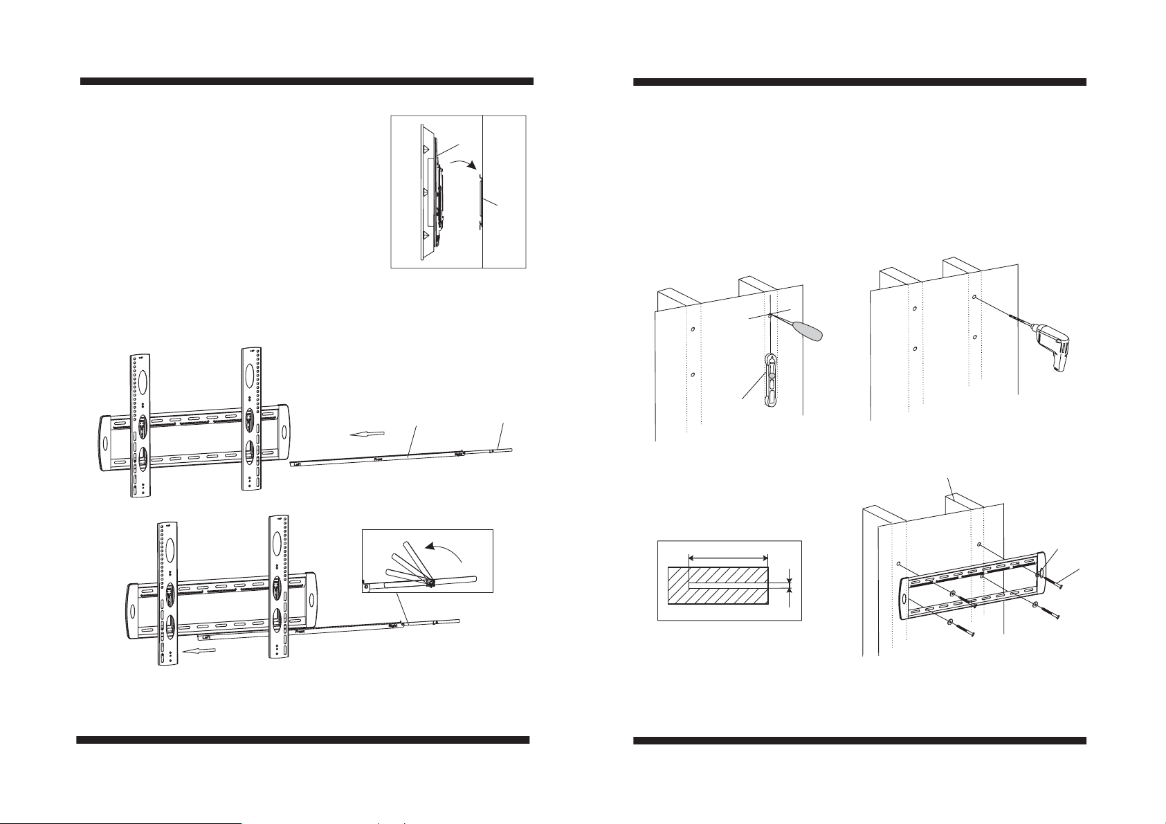
Part 3-Mounting the flat panel screen
Part 3-Mounting the flat panel screen
2,3
Hook the top of brackets onto the top flange
(2,3)
of wall plate(1). Then swing the screen down.
NOTE:
NOTE:
Always use an assistant or mechanical
1
lifting equipment to safely lift and position
heavy equipment.
Use the Locking bar(4) to prevent the TV from being removed or
accidentally knocked off of the wall plate.When the locking bar half
insertes into the wall plate , you can use the rotating rod(5) to make it
fully inserted.
Part 1a-Wood Stud Mounting
Part 1a-Wood Stud Mounting
Usewallplate(1)asatemplate,makesureitislevel,andmarkfourmounting
holes along the center lines of the wood studs. Drill four 3/16
””(5mm)dia
.
holes 2 (50mm) deep. Level wall plate(1) and attach to wall with four long
bolts(G and four washers(I . Tighten screws firmly Do not overtighten
)) . .
-6-
4
5
Stud finder
Wood stud
2 (50mm)”
I
G
Φ3/16 (5mm)”
-3-
Page 4
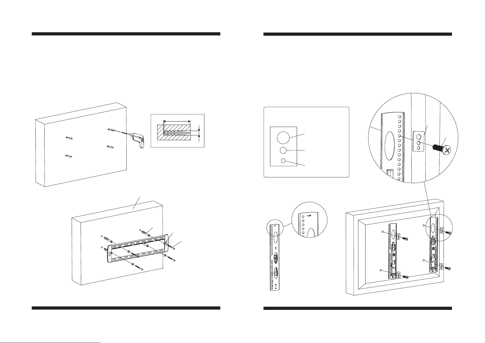
Part 1b-Concrete Wall Mounting
Part 1b-Concrete Wall Mounting
Part 2a-Attaching Brackets To Screen With Flat Back
Part 2a-Attaching Brackets To Screen With Flat Back
Level wall plate(1) and use wall as a template to mark four holes. Drill four 3/8
(10mm) dia. holes 2 (50mm) deep. Insert four anchors(H) into holes and
”
secure wall plate with four long bolts(G) and four washers(I).Tighten screws
firmly. Do not overtighten
.
2(” 50mm)
Φ3/8 (10mm)”
Concrete Wall
H
I
G
”
Center brackets vertically on back of screen. Select the small(A or B),
medium(C or D) or large(E) screws. Attach brackets to screen using four
selected screws and four square washers(F) at the top and bottom of each
bracket. Tighten screws firmly. Do not overtighten
.
Square washer(F)
F
Large hole for
M8 screws
Medium hole for
M5andM6screws
Small hole for
M4 screws
A-E
-4-
-5-
 Loading...