

Page 1

Brick, Concrete and Stone wall(Fig 2c):
Brick, Concrete and Stone wall(Fig 2c):
Using the wall mount as template to mark 6 holes location on the wall. There holes are
located at the top row of the slots and three more arelocatedatthebottomrow. The
outer holes must be fall to the left and right of the two holes in the middle of the
mount. Please make sure these holes are level and at least 6” between any two lines.
Pre-drill these holes with a 10mm drill bit to at least 80mm deep hole. Insert Wall
anchors(P) into each of these holes. Attach the wall mount to the wall using 6 Long
bolts(O) and washers(Q).
1
Q
O
Fig 2b
Step 3: Hanging display
Step 3: Hanging display
Firstly lift the bracket mounted display over the wall mount. And then hook the
brackets over the top of the wall mount. Rotate the display let the bottom of the
brackets hook over the bottom of wall mount, as shown in Fig.3a. Then put safe
bolts into the bottom of the brackets and lock it, as shown in Fig.3b.
Warning: Some TV require two people to lift, as we are not responsibleforany
Warning:
personal injury or product damage due to mishandling.
2,3
1
4
Fig 2c
Fig 3a Fig 3b
Fixed Flat Panel TV Bracket
Multifunctional double deck wall mount
INSTALLATION GUIDE
Item No.:PSW112Item No.:PSW112
Easy installing: Just hang up the display
Safety: locking by spining bolt on the bottom
Max load capacity:75kg(165lbs
TV size range: 36 ~55
,
""
)
-8-
IMPORTANT: If don’t understand about right install ways, please
IMPORTANT:
consult to normal installing specialist.
Page 2

Hardware List:Hardware List:
Step 2: mount to wall
AttachStep 2: Attach mount to wall
2
A-M
ID Description
Qty
1
2
3
42
A
B
C
D
E
F
G
H
1
1
1
4
4
4
4
4
4
4
4
N
Wall mount
Left bracket
Right bracket
Safe bolt
M4 mm×12 bolt
Mmm5×12 bolt
M× mm6 12 bolt
M× mm8 12 bolt
M× mm4 25 bolt
M× mm5 25 bolt
M6× mm25 bolt
M× mm8 25 bolt
3
1
4
ID
P
Qty
I
J
K
L
M
N
O
P
Q
R
S
O
Q
Description
4
M× mm4 40 bolt
4
M5×40mmbolt
4
M6×40mmbolt
4
M8×40mmbolt
4
1/4 -20×5/8 bolt""
4
Square washer
6
Long bolt
6
Wall anchor
6
Long bolt washer
8
9/16 Spacer"
8
1/2 Spacer"
R
S
First, determine the height of stand
The best height of stand is parallel to eyelevel of a person who sitting on a couch.
Normally, the horizontal distance of eyelevel is about 4’ from ground level.
The following two conditions are for determining the perfect height of stand:
1) the distance between wall and couch(Fig 2a).
2) the distance of eyelevel from ground level plus the distance measured from
eyelevel of a person sitting on couch with viewingangle of 15 (Fig 2a).
For example:
1) the distance of ‘a’ is 5’-7’, the distance of ‘b’ is about 1’
2) the distance of ‘a’ is 8’-13’, the distance of ‘b’ is about 3’
3) the distance of ‘a’ is 14’-17’, the distance of ‘b’ is about 4’
The perfect height of stand centre will be anywhere within b, where you feel
comfortable for viewing.
15 degree
viewing angle
°
b
eyelevel
a
Fig 2a
After determining the height of stand, follow the installation instructions in below
to install wall mount to different kinds of wall -wooden, brick, concrete and stone.
Woodenwall(Fig 2b):
Woodenwall(Fig 2b):
Using a awl or nail to make wherethenails are located,as shown as fig.2b.Distance
between two nails for fixing wall mount must not less than 12”. Pre-drill these holes
with a 5mm drill bit to a at least 80mm in deep hole. Please make sure these holes are
level and located at center. Use wall mount as a template to mark the location of other
three holes and drill the same holes. Fix the wall mount to the wall with 4 long bolts(O)
and washers(Q).
-2-
-7-
Page 3
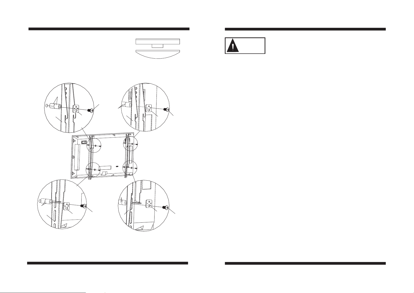
3. For display with protruding HDTV tune or deeply
curved backs(Fig b), two 9/16” spacers(R) or two
½” spacers(S) should be used. Stack two spacers
and then install them between display and the
bracket. As shown in Fig 1c.
R
I
R
3
N
WARNING
Fig b
M5 Fig bitM4 Fig bit
2
N
J
S
We are not responsible for any personal injury or product damage due to mishandling,
incorrect mounting, incorrect assembly or incorrect use of this product.
The supplied wall mounting hardware is not for use on steel stud walls or cold
Note:
cinder block walls. If you are uncertain about the nature of your wall, please consult a
qualified contractor. If the hardware you required is not included please contact your
local hardware store or the nearest Circuit City Stores.
Caution:This Product LCD /Plasma Wall Mount Bracket is intended for use only
Caution:
with the maximum weights indicated .See apparatus instructions .Use with products
heavier than the maximum weights indicated may result in instability causing possible
injury .
Step 1: Attach bracket to TV
Step 1: Attach bracket to TV
CheckyourTVmanualtoconfirmthediameterofbolttobeusedorchoosean
appropriate bolt according to size, height and position of the holes on your TV. See
pages 4-6 of these instructions for examples.
For correct installing, make sure that hook of every bracket must facing down. Use
selected bolt, spacers and washer for installing bracket at the back of display.
Adjust two brackets to equal heights and level. Once aligned, tightly secure the
bolts.
-6-
R
3
M6 Fig bit
IMPORTANT:
N
K
2
N
L
IMPORTANT
equipments and injure of person. Don't use electric drill to fasten any bolts.
Don't force the bolt into the hole, which will cause a damage of
M8 Fig bit
Fig 1c
-3-
Page 4
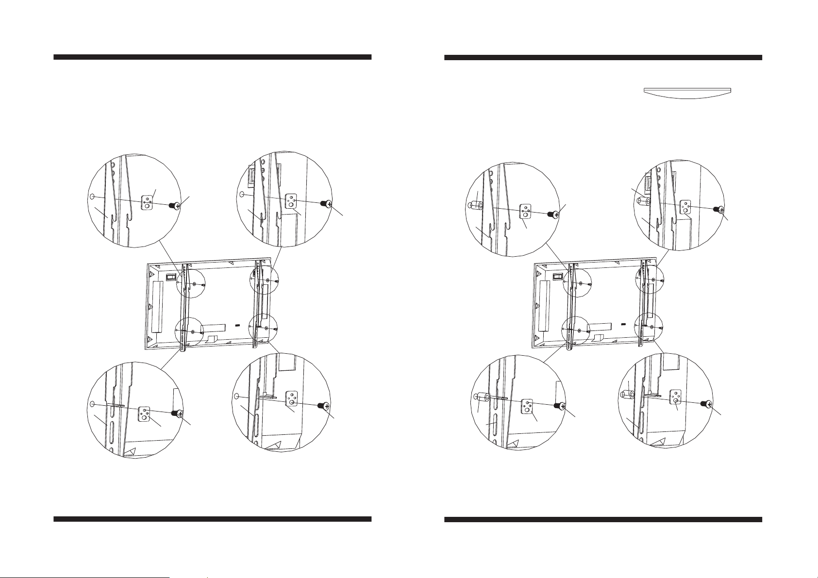
Following examples shows how to use bolts, spacers and square washers.
1.Somedisplays have vertical backs. No spacer is required. Install the bracket directly
to the back of display by using bolts and square washers provided. As shown in Fig.1a.
M4 Fig bit M5 Fig bit
2. Some displays have curved backs with
recessed mounting lands(Fig.a). It will
require the use of spacer. For this display,
install a 9/16” spacer(R) or ½”spacer(S)
between display and the bracket. As
shown in Fig 1b.
Fig a
M5 Fig bitM4 Fig bit
N
3
A
2
N
B
R
E
3
N
R
2
N
F
S
2
3
N
C,M
N
D
R
3
N
G
2
M8 Fig bitM6,1/4 -20 5/8 Fig bit""
N
H
M8 Fig bitM6 Fig bit
-4-
Fig 1a
Fig 1b
-5-
 Loading...