

Page 1

7000U /
Rev.:
D1
P/N:
19370902010
(PP-7000II / PP-7200L / PP-
PP-7200U) THERMAL PRINTER
Aura Series
USER’S MANUAL
FCC Notes:
This equipment generates, uses, and can radiate radio frequency energy and, if not installed and
used in accordance with the instructions manual, may cause interference to radio communications.
It has been tested and found to comply with limits for a Class A digital device pursuant to subpart
J of Part 15 of FCC Rules, which are designed to provide reasonable protection against
interference when operated in a commercial environment. Operation of this equipment in a
residential area is likely to cause interference in which case the user at his own expense will be
required to take whatever measures to correct the interference.
CE manufacturer’s Declaration of Conformity
(EC Council Directive 89/336/EEC of 3 May 1989)
This product has been designed and manufactured in accordance with the International Standards
EN50081-1/01.92 and EN50082-1/01.92 following the provisions of the Electro Magnetic
Compatibility Directive of the European Communities as of May 1989
Warranty Limits:
Warranty terminates automatically when any person other than the authorized technicians opens
the machine. The user should consult his/her dealer for the problem happened. Warranty voids if
the user does not follow the instructions in application of this merchandise. The manufacturer is by
no means responsible for any damage or hazard caused by improper application.
About This Manual:
Posiflex has made every effort for the accuracy of the content in this manual. However, Posiflex
will assume no liability for any technical inaccuracies or editorial or other errors or omissions
contained herein, nor for direct, indirect, incidental, consequential or otherwise damages, including
without limitation loss of data or profits, resulting from the furnishing, performance, or use of this
material.
This information is provided “as is” and Posiflex Technologies, Inc. expressly disclaims any
warranties, expressed, implied or statutory, including without limitation implied warranties of
merchantability or fitness for particular purpose, good title and against infringement.
The information in this manual contains only essential hardware concerns for general user and is
subject to change without notice. Posiflex reserves the right to alter product designs, layouts or
drivers without notification. The system integrator shall provide applicative notices and
arrangement for special options utilizing this product. The user may find the most up to date
information of the hardware from web sites: http://www.posiflex.com or
http://www.posiflex.com.tw or http://www.posiflexusa.com
All data should be backed-up prior to the installation of any drive unit or storage peripheral.
Posiflex will not be responsible for any loss of data resulting from the use, disuse or misuse of this
or any other Posiflex product.
All rights are strictly reserved. No part of this documentation may be reproduced, stored in a
retrieval system, or transmitted in any form or by any means, electronic, mechanical, photocopying,
or otherwise, without prior express written consent from Posiflex Technologies, Inc. the publisher
of this documentation.
© Copyright Posiflex Technologies, Inc. 2008
All brand and product names and trademarks are the property of their respective holders.
Part 1
Page 2

GETTING STARTED
CONGRATULATION
You have made a very wise decision by purchasing the easy loading;
low noise; high resolution; light weight; high reliability thermal printer Aura
(PP-7000II, PP-7200L, PP-7000U & PP-7200U) series of Posiflex products.
This series of printers has been elegantly designed for a Point-Of-Sale, kitchen
& kiosk application. The PP-7000U complies with UPOS (Unified POS) 1.8
standards and the rest models comply with UPOS 1.7 standards under Posiflex
UPOS driver support. The manufacturer of this printer not only wishes to take
this opportunity to congratulate your smart investment on buying this printer
but also likes to express the wishes for your prosperous future by using it.
PRODUCT BRIEFING
The Aura PP-7000II, PP-7200L, PP-7000U & PP-7200U series
printer uses thermal sensitive paper in form of a roll at a width of 80 mm
(standard) or 58 mm (option). These Aura series printers serve the stand-alone
desktop application as well as the application within a Posiflex integrated POS
system equally perfect.
The Aura PP-7000II series support two types of interface input
through different sub-codes to the model number. The interfaces are RS232 for
serial interface and Centronics for parallel interface. The Aura PP-7200L series
connects to a LAN port of Posiflex POS systems. The Aura PP-7000U series
connects to an USB port of Posiflex POS systems and simulates a RS232
device through driver and performs thermal printing particularly designed for
POS applications. The Aura PP-7000U series is already WEPOS (Windows
Embedded for Point Of Service) certified. The Aura PP-7200U series is a
similar model to PP-7000U redesigned particularly for high performance in
graphic application under Windows environment by removing the internal
serial communication limitations. Aura printer of different model number subcodes utilizes different cabinet color and accessory cable and switch setting to
accommodate the requirement of different interface.
The Aura PP-7000II, PP-7200L, PP-7000U & PP-7200U support a
guillotine type auto cutter for paper partial cut and a manual cut mechanism.
The Aura series also supports user’s company’s LOGO downloading for
superior performance. It even supports some enhancement capability for
reminder function to persons around. It can be used to drive a separately
purchased kitchen bell for such reminder function in noisy environment. This
printer also supports application in different countries of various kinds of
power systems by changing the power cord to the power adaptor. It offers
outstandingly high printing speed. This series make beeping sound as response
to Paper End or Paper Near End signals.
Part 2
Page 3

UNPACKING
Followings are items you may find when you carefully unpack the
carton that delivers Aura series printer. If there is any discrepancy or problem,
contact your dealer immediately. Be sure to save the packing materials in
case the printer needs to be shipped at some point in the future.
1). The printer itself
2). Thermal paper test roll 80 mm wide
3). One piece of spacer plate
4). One of the interface cables:
a.. Serial cable with 9 pin D sub Female to 9 pin D sub Male
connectors for Aura PP-7000II serial model
b.. Parallel cable with 25 pin D sub Male to 25 pin D sub
Female connectors for Aura PP-7000II parallel model
c.. No interface cable for PP-7200L
d.. USB cable for Aura PP-7000U / PP-7200U
e.. Option powered USB cable (P/N: 21863256800) for Aura
PP-7000U / PP-7200U
Length of the interface cable depends on whether the order includes
the power adaptor. When power adaptor is included, the interface cable is 6 ft
long for stand alone application. When the power adaptor is not included in the
order, the interface cable is a shorter one for integrated application in Posiflex
POS system.
5). One of the power sources:
a.. Power adaptor + power cord (depend on country type
ordered)
b.. Power supply cable (when no power adaptor and no
powered USB cable ordered)
6). This User’s Manual
7). One cable cover
OPTIONS
• 58 mm paper guide adaptor (can be modified at distributor’s site only)
• Kitchen bell
• Wall mount kit
• Model select: Standard, European, Arabian, Baltic, Bulgarian, Greek, Thai
and Latin II model
• Language to add to standard model: Japanese Kanji, Korean, Simplified
Chinese or Traditional Chinese
Part 3
Page 4

3 4 1
PP-7000
U
6 7 4 10
PP-7200U
1
Power LED
PP-7000
II
3 1 4 5 8 4 3 1
PP-7200L
Window Plate
Top Cover
Hood Release
PRODUCT PICTURES
Top View
Top Hood
Error LED
Paper Out LED
FEED Switch
Cutter Cover
Bottom Cover
Power Switch
Front View Bottom View
Front View Bottom View
Cable Cover Screw Hole
Screw
Power Switch
Setup Window
Rear View
2
9
3
Screws
7
6
Part 4
Page 5

The numbered items above are:
1). Power Connector
2). Parallel Connector
3). Frame Ground
4). Peripheral Connector
5). Serial Connector
6). Interface Bracket Screw
7). USB Connector
8). LAN Connector
9). Reset Pin Hole
10). Service Serial Port
Cable Cover
INDICATORS
• Power LED: green
• Error LED: red
• Paper Out LED: red
Tenon
Screw Hole
Tenon
Cable Cover
Part 5
Page 6

PP-7000
II PP-7200L PP-
7000
U
Pix. 2
Release Button
Pix. 1
Pix. 3
PP-7200U
QUICK START-UP
LOADING PAPER
Desk Top Application
1. Slide the hood lock toward the front of the
printer to release the hood as in Pix. 1.
2. Raise the released hood
wide open manually as in
Pix. 2.
3. Drop the thermal paper roll
inside the printer in
orientation as shown in Pix. 2.
4. Close the hood back leaving
the tail of the paper roll
coming out of the opening
between the hood and the top
cover as in Pix. 3. Tear off excessive paper.
When to Replace Paper
Whenever the printer gives paper out signal or a red line appears on
the thermal paper, it is the proper timing for replacing the paper. Do not wait
till the print engine is dragging the paper roll at the very end. Remove the
leftover and replace a new paper roll as illustrated above to prevent excessive
paper dust in the printer and consequently possibility for paper jam.
for PP-7000II. The serial connector is a 9-PIN D sub Female connector at the
CONNECTING CABLES
Connection Area Pictures
Serial Connection
All the external connectors are in the recessed area at the rear bottom
Part 6
Page 7
Close Up View
of
Normal
Printer End Plugs in
right in the picture above. Apply the male connector of RS232 cable to this
port for serial application. Please note that when serial connection is used,
there must be no cable connection at the parallel port on the printer. The
default protocol used in serial connection is 19200 bps, none parity, 8 data bits,
1 stop bit. Set in setup window the switch positions both 1, and 2 to OFF
leaving the rest unchanged as factory default setting
Parallel Connection
The parallel connector is a 25-PIN D sub Male connector at the
leftmost location in the connector area for PP-7000II. Apply the female end of
the parallel cable at this port for parallel application. Please note that when
parallel connection is used, there must be no cable connection at the serial port
on the printer. Please also note that to keep parallel interface in fast operation,
please adjust in setup window the switch positions both 1, and 2 to ON
leaving the rest unchanged as factory default setting.
LAN Connection
The LAN connector is a 8-PIN RJ45 connector in middle left of the
connector area for PP-7200L. Please use a LAN cable of CAT 5 with proper
length to connect the LAN connector on the printer to the LAN HUB as
appropriate. Please also note that to keep LAN interface operative, please
adjust in setup window the switch positions both 1, and 2 to OFF leaving
the rest unchanged as factory default setting. DO NOT CONNECT THE
PERIPHERAL DEVICE TO THIS PORT!! The LAN port is 10/100BaseT
compliant.
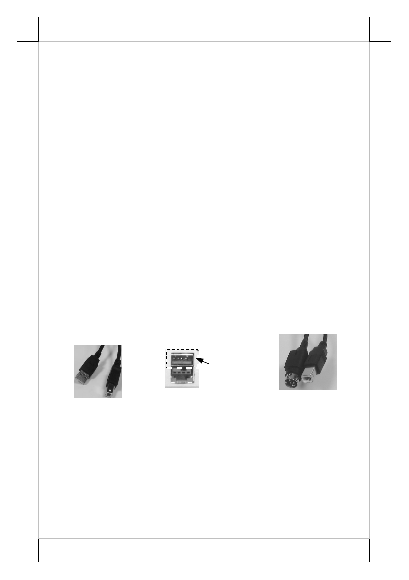
Type A
Normal USB Plugs
input namely a Normal USB interface and a + 24V Powered USB interface.
The cable for normal USB connection has a type A normal USB connector at
one end that is a more or less flat shape 4-PIN connector and a type B normal
USB connector at the other end that is a more or less square shape connector
as in picture above. The Powered USB Cable (P/N: 21863256800) has 3 plugs:
a + 24V Powered USB plug at one end, a type B normal USB plug and a 3PIN power plug at the other end.
USB Connection
Type B
USB
Portion
Powered USB Port
Powered USB Cable
The Aura PP-7000U/7200U series support two types of USB interface
Part 7
Page 8

Use the normal USB Cable (P/N: 21863250800) to connect to a
normal USB port or the normal USB portion of the powered USB connector of
host system. The power adaptor is required in this normal USB application.
Use the powered USB cable to connect a +24V Powered USB port of Posiflex
POS system with the powered USB plug, and connect to the USB port in PP7000U/7200U with the type B normal USB plug and the 3-PIN power plug to
the 3-PIN power jack in PP-7000U/PP-7200U. The power adaptor can be
deleted in this powered USB application. Please always press the locking strap
first before disconnecting the Powered USB cable. Please visit our web site
http://www.posiflex.com or http://www.posiflex.com.tw for detailed
information of the USB driver installation if required. Set in setup window the
same way as in serial connection, i.e. switch positions both 1, and 2 to OFF
leaving the rest unchanged as factory default setting.
Peripheral Connection
The peripheral controller is a 6 pin RJ11 type modular jack. With use
of Posiflex cash drawer cable 21863018010 (CCBLA-180-1) come with cash
drawer, this port can control a Posiflex cash drawer CR3100 or CR3200 or
CR4000 or CR4100 or CR-6310. If a Posiflex special split cable 21863023800
(CCBLA-238) is used instead, this port can control two cash drawers of above
models.
When the printer is used as a kitchen printer, please use this port for
kitchen bell connection instead.
Power Connection
The power connector is a 3-PIN jack between the peripheral
connector and the parallel connector for PP-7000II or between the peripheral
connector and the B type USB connector for PP-7200U and is at the rightmost
for PP-7000U & PP-7200L. Either a Posiflex supplied power adaptor or a
printer power cable from a Posiflex POS system can be connected to this
connector to supply power for this printer. During insertion of the power plug,
be sure to hear the click to obtain a firm contact.
CAUTION: Before doing the insertion or extraction of the power plug, be
sure to pull the outer sleeve of the plug backward to release the
internal latch. Failure to do this could damage the power plug. Such
damage is considered as an artificial destruction and is not covered
by the warranty.
Part 8
Page 9
Sensor Head
Install Cable Cover
Check the bottom view of the printer, the 4
screws for the printer itself are in quite deep holes. Insert
the tenons of the cable cover into the 2 printer screw
holes nearest to the connection area. Apply a cable cover
fixing screw at the matched screw holes as circled in the
bottom view picture at right.
Power On
When all the above cable connections are made
correctly, you may connect your power adaptor to the
wall outlet. Make sure that the type of power cord and
the voltage requirement of the power adaptor meet the local power conditions.
Now the printer is ready for power on.
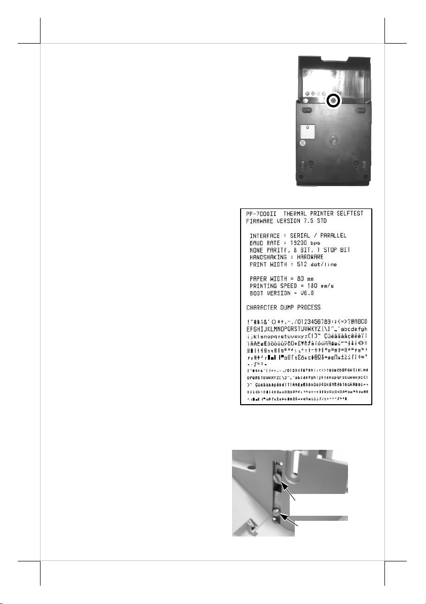
Self Test
Press and hold down the feed
button while turning the on / off switch on.
The printer will then perform a self-test. A
sample slip of self-test result is printed as in
the sample at right. Please note that both
serial and parallel interfaces are indicated.
That means the printer is working on an
auto-sensing and auto-select algorithm.
The header is printed in text mode
and the rest part of this slip is printed in
page mode. If FEED button is pressed at
this moment, a font table will be printed in
text mode again. To exit the test printing,
please turn the printer off and on again.
SPECIAL ADJUSTMENTS
Paper Near End Sensor
The near end sensor for paper
roll in the printer is able to have the
printer work with paper rolls of several
bobbin sizes. Please refer to the picture at
right from inside the paper roll
compartment that there are a fixing screw
and a sensor head in the wall. Slightly
release the fixing screw to adjust the
Fixing Screw
Part 9
Page 10
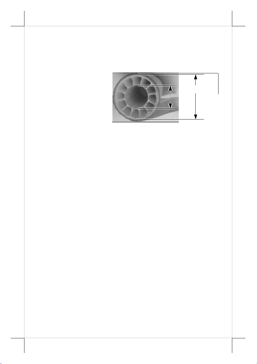
Bobbin I.D.
Bobbin O.D.
Thermal
position of sensor head. The acceptable paper roll bobbin outer diameter is
between 18 and 22mm. This adjustment allows sensor activation on paper roll
overall diameter between 21 and 23.6 mm unless for too light bobbins.
Remember, for smaller roll diameter, the sensor head should go higher.
Paper Roll Replacement
When the paper roll
to put (back) in is already
nearly used up, the paper roll
must be placed in the way that
the paper roll touches the
sensor head from the outer
surface but never allow the
Paper
Surface
sensor head to ride on the
bobbin body between the inner and outer diameter of the paper roll bobbin nor
to go into the inner diameter of the paper roll bobbin. It is also noticed that
some market available paper roll has extremely light bobbin, easily causing the
paper roll to go off position when paper feeding with low remaining paper. In
this case, the paper near end sensor may function abnormally and it would be a
good solution to set in the setup window to have the printer to send busy only
when input buffer is full and not based on every off line signal.
Spacer Plate
If the paper roll is of width less than the standard 80 / 58 mm, it may
run away from the paper near end sensor during application resulting in an
error status. In this case, please stick the spacer plate to the wall opposite to the
paper near end sensor in the paper roll compartment. Each spacer plate
compensates 1 mm paper roll width shortage. There will be 1 spacer plate in
the accessory of the printer. If the user uses narrower paper roll and requires
more spacer plates, it can be purchased from Posiflex.
Paper Cutting
The paper advance after a protective cut is set to 12 mm. In case the
user uses direct cut instead of protective cut to have something like a logo
printed on top of each slip, it is also highly suggested to print the logo and
necessary paper feeding to make 12 mm paper advance right after each cut to
prevent curling up and jamming of paper front edge inside the paper exit slot.
Wall Mount Application
In wall mount application, the paper near end sensor will not work
properly and it is suggested to set in the setup window to have the printer to
send busy only when input buffer is full and not based on every off line signal.
Part 10
Page 11

INSTALLING DRIVER
There will always be a Posiflex Product Information CD or a separate
CD of similar nature but specifically created for the product delivered. Please
find the appropriate subfolder from the non-specific Posiflex Product
Information CD and check the information file like “readme” or installation
guide or application guide and follow the instructions inside.
LAN PRINTER SPECIFIC ISSUES
Web Manager
The default static IP for the PP-7200L is 192.168.192.168 and default
listen port is 9100. User may set his own IP to the same network segment and
use any browser to connect to the printer IP to configure the LAN setup of the
PP-7200L including changing the printer IP for application according to his
network administrator’s request. However, DHCP is not supported.
Reset Pin Hole
As the LAN setup for the PP-7200L can be set freely, if the changes
are not well registered some troubles could be introduced. Therefore, in PP7200L, there is a “Reset pin hole” near the LAN connector. Use something like
a ball pen tip or straightened end of paper clip to push and hold for at least 5
seconds into this hole will reset the LAN setup of the printer back to the
default values at delivery so the user may re-do all setup. The LAN setup can
be viewed in second paragraph of self-test printout for the PP-7200L.
LAN POS Printer Manager
This utility can be used to manage multiple PP-7200L’s connected in
same network under Windows as long as there is no conflicting IP in the
network. This utility can assign to each LAN printer a different device name
for easy recognition. In case of confusion, please check the MAC addresses
listed in this utility against the MAC address label you can find under each
printer.
Printer Driver Setup
Any PC connected in same network can use TCP/IP to use PP-7200L
in the way like a directly connected local printer. So, for direct I/O control by
tools like “HyperTerminal” all commands applicable to the serial or parallel
interface model can work on PP-7200L in the same way as PP-7000II except
the port must be TCP/IP with the IP address of the printer. Similarly, for
Windows printer driver setup, please “Add Printer” and select for “Local
printer” and select port “TCP/IP” with the printer IP address then use the same
Windows printer driver of PP-7000II for PP-7200L.
Part 11
Page 12
OPERATION GUIDE
MAINTENANCE GUIDE LINES
• Always turn off and disconnect power before opening the cover.
• The areas around the print head and motor become very hot during and just
after printing, DO NOT touch them.
• When handling the interior of the thermal printer, please pay attention not
to be hurt by any sharp edge of the metal parts.
GENERAL CLEANING
Please use soft hairbrush or compressed air to clear away any dust or
paper scraps accumulation inside the printer. Check also the area of the autocutter regularly.
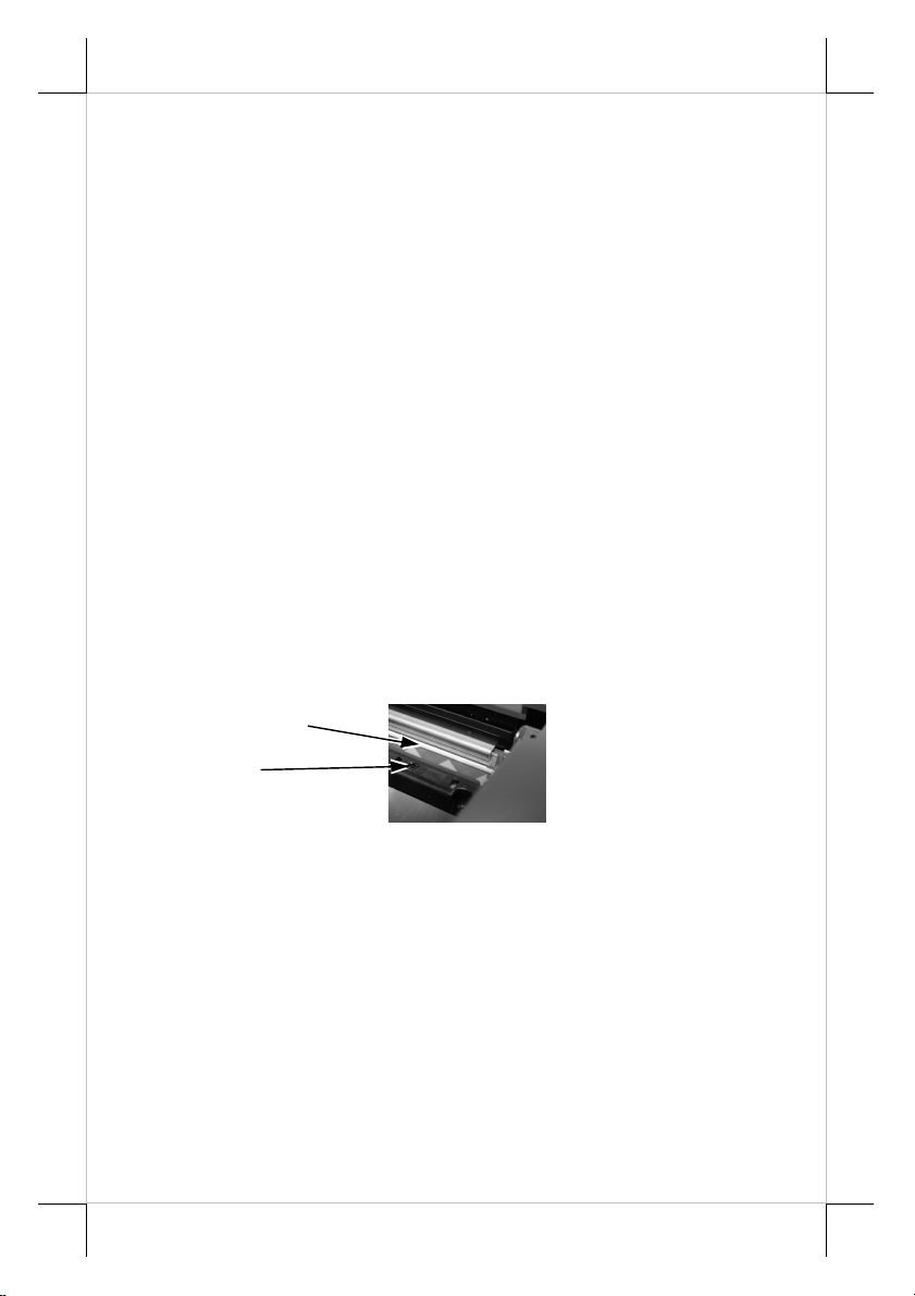
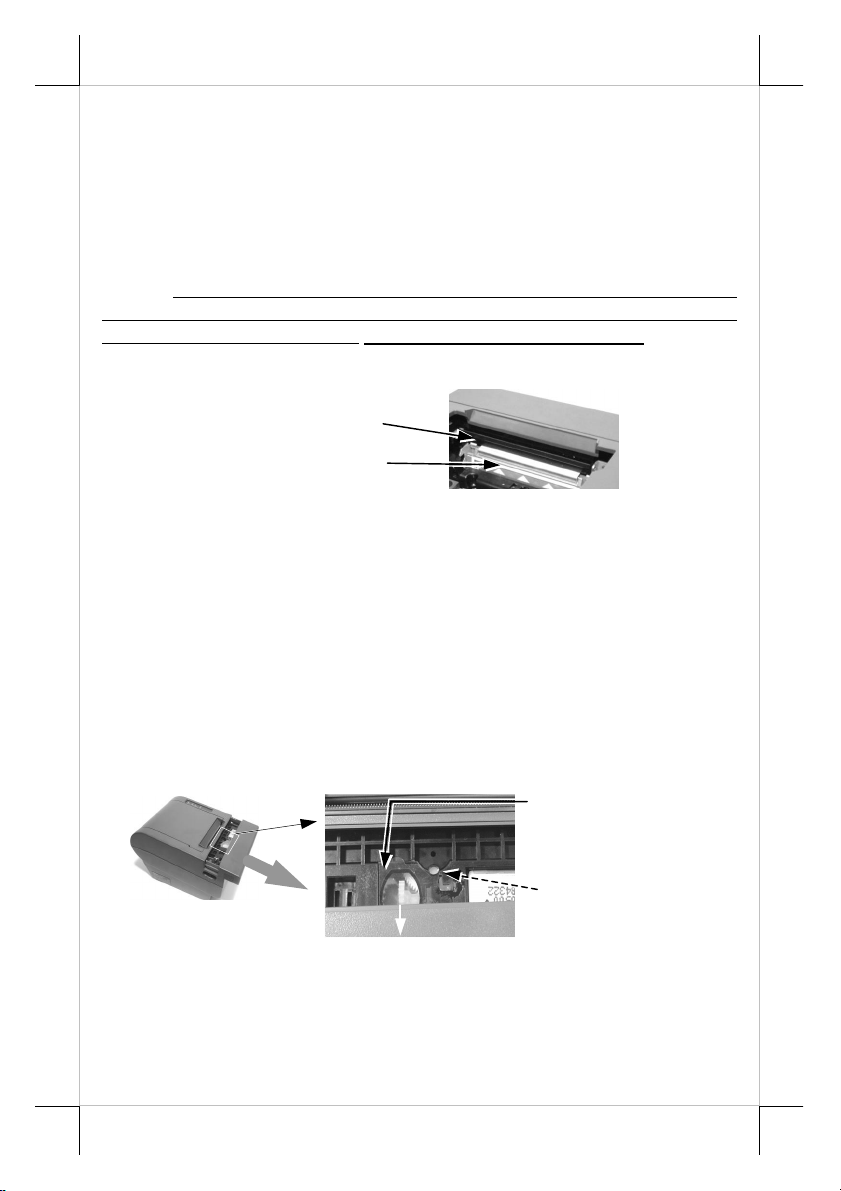
PRINT HEAD CLEANING
The print head is located underneath the roll paper passage at the exit
as in the picture below. You can clean the thermal elements of the print head
and paper sensor gently using a cotton swab moistened with isopropyl alcohol
solvent.
NOTE: Never do this when print head is still hot
Do not touch the print head thermal elements
Do not scratch the print head
Thermal Elements
Paper Sensor
Before putting back the paper roll for printing, alcohol solvent must
be dried completely.
TROUBLE SHOOTING
This section gives solutions to some printer problems you may have.
General Problems
No LED lights up on control panel when switched on –Make sure
that the power supply cables are correctly plugged into the printer, the power
adaptor and to the power outlet. Make sure that power is supplied to the power
outlet. If the outlet is controlled by a switch or timer, try use another outlet
Printing Problems
Nothing can be printed with ERROR LED flashing – Most
Part 12
Page 13

possible cause for the flashing Error LED is that the printer has been printing
for quite a period of time and the print head temperature become too high.
After few minutes under normal ventilation, the print head should be able to
cool down and the Error LED will stop flashing. Printing will resume after
cooled down. If this is not the case, contact a qualified service person.
Nothing can be printed with ERROR LED ON – Check the Paper
Out LED. If it is ON, most probably either the paper roll is not installed or the
paper roll is at or near the end. Install a new paper roll. If the Paper Out LED is
OFF, please check if the print hood is properly closed. There are 2 internal
check points inside the printer to assure the locking of the hood for a decent
printing. Therefore any dislocation of the hood may cause an error status and
inhibition to printing. Press down the hood at middle of the opening when
closing it till it audibly clicks into place. If both situations are not the cause,
please try pulling the hood lock forward. If the top hood won’t release
automatically, check for paper jam described in next item.
If there is no paper jam and the print head is not overheated, turn off
the printer and wait for half a minute then turn it back on. If the problem still
remains, contact a qualified service person.
Nothing can be printed with ERROR LED OFF – Try to run selftest according to previous chapter to check if the printer itself works properly.
If the self-test passes, check the following:
1). Check the connection of the interface cable at both the
printer and computer ends. Also make sure that this cable
meets the specification required for both the printer and the
computer.
2). Check the printer data communication settings against the
computer. The printer settings can be found easily on the
self-test print out.
If the problem remains or the self-test fails, contact your dealer or a
qualified service person.
Poor printing quality – Contaminants like paper scraps and dusts on
the thermal print head can lower the print quality drastically. Clean the print
head as described in previous section.
Printer trembles when printing – Since PP-7000II series prints at
180 mm / sec that is extremely high speed, the printer may tremble due to
frequent engagement of the brake and acceleration of the motor. Such situation
in turn can be consequences of very complicated printer operation command or
heavily dense printing (like in inverse printing) in print content or irregular /
insufficient data flow received from the host. When this happens, the print
speed will be dragged down drastically since the motor has to be stopped
frequently. Avoiding such drawbacks can free the printer from trembling and
degraded performance. As a common practice, increasing the communication
Part 13
Page 14
baud rate could be a smart decision to this situation. (No need to change baud
rate if no trembling occurs to eliminate possible data error rate.)
Paper Jam Problems
Paper is jammed inside the printer – Turn off the printer and open
the print hood by releasing the hood lock. Remove the jammed paper and
reinstall the paper roll. Close the hood properly and firmly. Then turn on the
printer for operation.
If the auto cutter is jammed, the print hood will be locked. Please first
resolve the auto cutter problems per description in next item and then come
back to deal with the paper jam. Never force open the print hood. Please also
clear away any contaminants accumulated in the cutter track above the thermal
elements.
Auto Cutter Track
Thermal Elements
Auto Cutter Problems
In case any foreign materials like a staple or paper clip or excessive
paper scraps fall into the auto cutter mechanism the auto cutter may lock up
and so does the print hood. In such case, please pull the cutter cover forward to
expose the cutter mechanism. Apply some mechanical assistance in below
procedures to help resetting the cutter blade back to its home position. Please
lift up if exist a transparent protective cover over the adjustment wheel with
the printer powered off. Turn this wheel downward for 4 or 5 strokes. Aim the
guide of the cutter cover and push it back to position to close the cutter cover
and turn the printer power on to see if the auto cutter lock up problem is
resolved.
Lift transparent
protective foil
Open Cutter Cover
when hood locked
Turn the wheel downward for few strokes.
Alignment window
If the problem is not automatically resolved by above procedures,
please power off the printer and open the cutter cover again. Check in the
alignment window while turning the gear downward as above or with a small
Part 14
Page 15
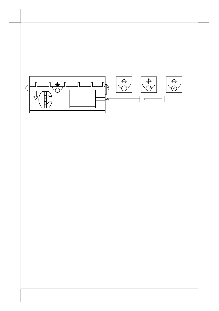
Diagram C shows the correct alignment
Phillips screwdriver at the right side of the print mechanism. When the cutter
blade returns to its standard position, a hole in the plastic gear will show up in
the window as illustrated in diagram C below. Close the cutter cover when
finish. The lock up of the print hood can then be released after this problem
solved.
Please use manual cutter as temporary alternative measure once the
auto cutter malfunctioned.
Alignment Window
Advanced Analysis Tool
This printer supports Hexadecimal Dump for experienced user to
view exactly what data is received by the printer. This can be useful in finding
software problems.
To start the dump mode: Turn off printer; Open print hood; Hold
down FEED button while turning printer on; Close the hood.
To stop the dump mode: Press the FEED button to print out the last
line; Turn off the printer.
During dump mode: All commands except DLE EOT and DLE ENQ
are disabled.
A B C
position to release the top cover.
USEFUL TIPS
• Please note that only those qualified technicians may adjust several
jumpers for some technical settings. Please visit our web site
http://www.posiflex.com or http://www.posiflex.com.tw for details of the
technical information such as driver installation, DIP switch settings and
command sets etc. if required.
• Place the printer on a sturdy, level surface.
• Choose a place that is well ventilated and free of excessive dust, smoke or
fume.
• Do not put the printer under direct sunlight or near a heater.
• Ideal room temperature is from 5ºC to 40ºC. Ideal humidity is from 20% to
85% RH (no condensation).
Part 15
Page 16

• Do not set any liquid or drinks such as coffee on the printer case.
• Do not touch any metal part to avoid possible electrostatic damage.
• Do not touch the areas around the print head and motor during or right after
printing. It can be very hot.
• Do not allow the cut receipt to slide back into the cutter during the
operation. As this would lead to multiple cutting at the lower edge of a
receipt and the multiple cut thin slips tend to cause mechanical malfunction.
• Use a grounded AC power outlet with only the power cord and power
adaptor furnished with the printer.
• Do not use a power outlet of a circuit shared with any equipment that uses
a lot of power or causes great electrical noises, such as a copier, electric
motors or a coffee maker.
• Do not use thermal paper containing Sodium (Na+), Potassium (K+) and
Chlorine (Cl-) ions that can harm the print head thermal elements.
• If the surface of thermal paper is scratched with a hard object such as a nail,
the paper may become discolored.
• If thermal paper touches diazzo copy paper immediately after copying, the
printed surface may be discolored.
• Use only water paste, starch paste, polyvinyl paste or CMC paste when
gluing thermal paper.
• If thermal paper touches anything containing phthalic acid ester plasticizer
for a long time, the image formation ability may be reduced or the printed
image may fade.
• Use of volatile organic solvents such as alcohol, ester and ketone or some
adhesive tapes on thermal paper can cause discoloration.
• Thermal paper must not be stored with the printed surfaces against each
other as the printing may be transferred between the surfaces.
• Since the paper roll is highly thermal sensitive, please keep them in a dark
place that is 20º and 65% RH when not installed in the printer. Avoid
extended exposure to direct light. Use only products made from
polyethylene, polypropylene or polyester for storage of thermal paper.
Part 16
Page 17
SPECIFICATIONS
PRINTER
ITEM SPECIFICATION
Printing method Thermal sensitive line dot method
Effective printing width 64 mm
Thermal head configuration 512 dots / line
Printing speed 180 mm /sec.
Paper feed method Friction auto-feed
Paper load method Drop and use
Auto-cutter capability Partial cut (1 point at center left)
Manual cutter Saw tooth blade
Dot Pitch 0.125 x 0.125 mm
Input power type DC
Input voltage 24 V + / - 5 %
Dimension (mm) 148 (W) x 199 (D) x 144 (H)
Weight 1.35 Kg net
PAPER
PAPER TYPE THERMAL ROLL PAPER
Paper roll formation External side is heat-sensitive side
Paper width 80 (or 58) + 0 / - 1 mm
Paper roll outer diameter 83 mm max.
Paper roll inner diameter 12 + 1 / - 0 mm
Paper thickness 60 ~ 80 um
POWER ADAPTOR
ITEM REQUIREMENT
Input voltage 100 V AC ~ 240 V AC
Input frequency 50 ~ 60 HZ
Input current 1.8 A MAX. @ 115 V AC
Output voltage + 24 V DC
Output power 60 W
Static load 0 A ~ 2.5 A
Output regulation + / - 5 %
MTBF 30,000 HRS
EMI standards VDE – A, FCC – A, VCCI – A
Part 17
Page 18
SERVICE WINDOW SETUP
PRINTER
On bottom cover of the Aura series thermal printer, there is screwed a
metal plate for setup window. In this window, there is a 8 position DIP switch
for printer setup. Please use proper tool to change the switch setting when
necessary. The switch position counting starts from the nearest edge of printer.
The ON direction points to the connector area of the printer. The OFF
direction points to the power switch. The functions of each position may
evolve with the revisions of the firmware. The information below applies to
the latest version to the date of print of this manual.
This 8 position DIP switch works as following:
Switch
position
1
2
3
4
5
6
7
8
parity check set according to position 3, number of data bits always set to 8,
and stop bit set to 1. When the interface used is anything other than RS232,
please set these 2 switches only at exactly the specified combination.
SW Pos. 1
SW Pos. 2
Baud rate or
Interface
In Aura, it is selectable between even and none.
When it is set to ON, the printer transmits an “XOFF” for busy and sends an
“XON” for not busy. When it is set to OFF, the printer signifies the busy status
over hardware signals that can be detected by the host as “DSR” or “CTS”.
When parallel interface is used, both switch positions 3 and 4 should be set to
OFF.
to host only when input buffer is full. When it is set to OFF, busy signal is sent
RS232 baud rate definition or Parallel interface definition
Even parity None parity
XON handshaking Hardware handshaking
Busy on “buffer full” Busy on “off line”
Immediate cut Protective cut
CR code effective CR code ineffective
Factory internal setting Application standard mode
Effect of positions 1 & 2 on baud rate is defined as in table below with
ON OFF ON OFF
ON ON OFF OFF
38400 bps
(Parallel)
Switch position 3 defines the parity check regulation in serial interface.
Switch position 4 defines the handshaking method in serial interface.
For switch position 5, if the switch is set to ON, the busy signal is sent
ON OFF
(ref. separate table below)
4800 bps 9600 bps
19200 bps
(RS232/LAN/USB)
Part 18
Page 19
interface w/ auto
to host whenever an off line status occurs. Therefore, signals including the
paper near end detect will generate busy signal to the host. Consequently, the
printing may be stopped even when there is still a long way to go before the
paper roll is actually exhausted. Taking the paper out beep into consideration,
the printer will keep on beeping at Paper End (completely no paper) till paper
is replaced when S1-5 is ON. Yet when S1-5 is OFF, the printer will keep on
beeping every 3 seconds at Paper Near End (still long paper in replace) till
paper is replaced.
For switch position 6, when it is set to OFF, there will be a 20 mm paper
feed before cutting when software does not define this point and there will be
further 10 mm paper after cutting to prevent paper jam. Before setting this
switch to ON, please make sure that your software will take care of enough
paper feed for the paper jam prevention issue.
For switch position 8, when it is set to ON in the field, the printer maybe
subject to unpredictable damages and must be strictly prevented.
The factory default for each position is listed below:
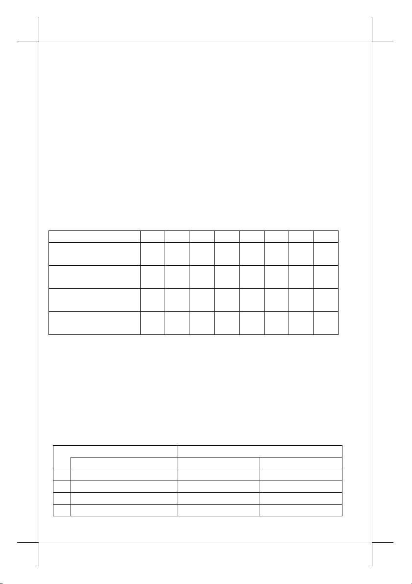
Switch Position 1 2 3 4 5 6 7 8
Serial interface w/
auto cutter
Parallel interface w/
auto cutter
USB interface w/ auto
cutter
LAN
cutter
OFF OFF OFF OFF OFF OFF OFF OFF
ON ON OFF OFF OFF OFF OFF OFF
OFF OFF OFF OFF OFF OFF OFF OFF
OFF OFF OFF OFF OFF OFF OFF OFF
more technical settings. To access these setup, please first turn off the printer
power and disconnect every cable from the printer. Remove 4 screws from
bottom of printer and remove the plastic bottom cover with the power switch
pressed. The 4 position DIP switch seats beside the 8 position DIP switch for
setup window with the switch position counting starts from the nearest side to
the 8 position DIP switch.
ê
1
2
3
4
INTERNAL SWITCH
There is an extra internal 4 position DIP switch in PP-7000II series for
This 4 position DIP switch works as following:
Switch position Setting Effect
Function ON OFF
Factory internal setting Disable Default
Paper width 58 mm 80 mm
Line format 576 dots / line 512 dots / line
Reserved N. A. N. A.
Part 19
Page 20
在居住的環
可能會造成射頻干
使用者會被要
T31454
The Switch position 1 default set to ON. The print speed is fixed at 42.5
lines/sec.
Switch position 2 is usually set to OFF for use with 80 mm paper width.
When the printer is installed with the 58 mm paper guide adaptor for use with
the paper roll of 58 mm width, the switch should be set to ON.
Switch position 3 is usually set to OFF for ESC/POS command
application that prints at 512 dots / line. Only technical users shall set this
switch to ON and make the printer work in the 576 dots / line format.
SERIVCE SERIAL PORT
There is an extra 9 pin female D sub connector for PP-7200U model in
connection area. This port is designed for technical service only. DO NOT
connect it for other purpose!
警告使用者
這是甲類的資訊產品,
境中使用時,
擾,在這種情況下 ,
求採取某些適當的對策。
Part 20
 Loading...