


7INCH WIDE TFT LCD MONITOR

Precautions
Please read this manual completely and carefully prior to attempting to install your new car video
equipment. Install correctly, your new equipment will provide you with year of enjoyable and safe usage.
Installation of this equipment in any portion of a vehicle which impairs or distracts the driver is improper
and dangerous. We assumes no liability whatsoever for failure to follow the proper installation of this
products.
1.Do not operate this equipment while driving-safe driving should always be your highest priority.
2.Do not install components in areas which are susceptible to rain, moisture direct sunlight, extreme
heat or cold, excessive dust, dirt or humidity.
3. Immediately unplug the power cord and send the monitor to your local dealer or service center as
soon as possible:
a) if there is smoke or any peculiar odor present during use
b) if there is damage to any of the internal components
4. To avoid damage to the monitor and risk of electronic shock, do not permit any of this equipment to
become damp or wet from water or liquid. If this does occur, immediately unplug the power cord and
send the monitor to your local dealer or service center as soon as possible.
5. Do not attempt to repair, open or dissemble any of the components. Dangerous high voltages are
present which may result in electric shock.
6. Use only a power source with 12 volts DC (negative ground).
7. Do not place objects on or suspend objects from the power cord, as this may damage the cord.
8. Do not twist or place the power cord near any source of heat in the vehicle.
9. Do not attempt to repair a damaged, broken or faulty power cord. Replace it with a new one immediately.
10. Avoid dropping any metal objects or inflammable items into the monitor ventilation slots.
1 1. After the monitor is installed, do not arbitrarily pull it down or strike it. This may loosen the mounting
screws and cause it fall down.
1.

Control and layout for the monitor
2
Notice: some functions are work by remote control.
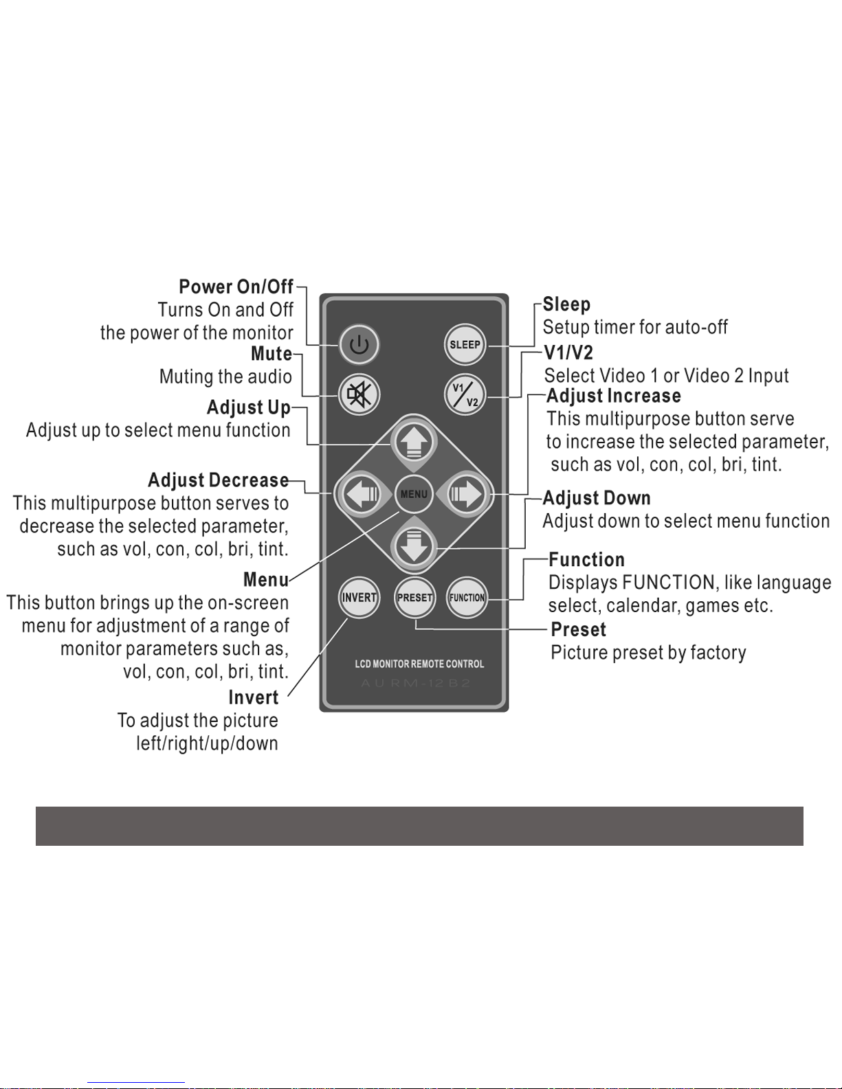
Control and layout for the remote control
3
Notice: If the monitor does not have the function, the button would not be work.
2.
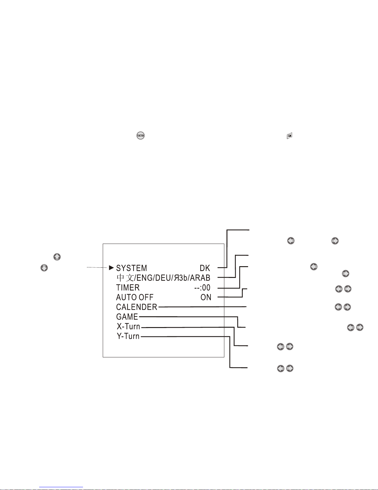
Function
Press FUNCTION button< > on the remote or press manual button< > twice from
the monitor to call out the function menu.
FUNCTION
PRESS UP < > OR
DOWN < > BUTTON
TO SELECT
Fixed
Press left < > or right < >
button to select your favorite
display language
Press left button < >to adjust
hours & press right button < >to
adjust minute
Press left or right button < >
to call out the calender
Press the left or right button < >
to call out the game
Press left or right button < >
to select auto on/off
Press < > to invert the
picture left or right
Press < > to invert the
picture up or down

Games
Press < > to enter the games.
Start --Menu Button < >
Move --Down Button < >
Roll --Up Button < >
Exit --Mute Button < >
Level --AV Button < >
Pause --Menu Button < >
Move Left --Volume Button < >
Move Right --Volume Button < >
Calendar
Press FUNCTION < >to call out the function menu,
then Press < > to select CALENDAR and
press left or right to < > to call out the CALENDAR
Adjust increase of year, press < > button
Adjust decrease of year, press < > button
Adjust increase of month, press < > button
Adjust decrease of month, press < > button

Installation
Video 2 input (yellow)
Ground (black)
DC 12V power input (red)
Remote Control replacing batteries
PULL OUT
PUSH
1) Always use new batteries when replacing the old set.
2)Do not attempt to charge, short-circuit, disassemble, heat or burn used batteries.
3)Battery replacement is necessary when remote control acts sporadically or stops
operating.
4)Do not drop, apply shock or step on the remote control
5)Do not spill water on the remote control
6) Do not place objects between the remote control and remote sensor.
7)Do not use remote controls for other equipments at the same time.
8)If the MONITOR does not operate even when operating the remote control from
a close range, it is time to replace the batteries (use CR-2025), refer to the label
on back of the basic control.
Video 1 input (red)
Power Cord
(Female)
4

Step of install headrest housing
6
Setup work
remove the headrest and set it in an uncluttered
work area. Take the appropriate precautions to
ensure that it is not damaged during the installation.
Unscrew it and takeaway the back cover before
install to headrest housing or sun-visor housing
CAUTION: make sure the screw are not long
enough to go through the headrest!
If you have any doubts about this type of
installation, please consult your local mobile
electronics retailer. Cutting and make holes in
the headrest will cause damage which is
expansive to repair.

Remove foam & obstructions
Carefully peel back the material. Set the
adjustable blade to one inch depth and cut
around the edges of the hole, staying 1/4 inch
inside the edge. Pull up one corner of the foam
and use the blade to cut underneath. Remove
small section at a time, using the pull up and
cut method for uniform depth. Use a dremel or
other appropriate tool to remove other
obstructions. Insert the monitor to measure the
fit and make adjustments if necessary
7
Measurements
Push on the headrest with your fingers to make
sure there are no obstructions that would hinder
the installation. Use the paper template to mark
the area to be cut.
Cut the headrest
using an adjustable-depth blade, start
your cut 1/4 inch inside one corner and
cut diagonally across, stopping 1/4 inch in
from the other corner. Repeat the procedure
for the other two corners.


Step of install sun-visor housing
Measurements
Push on the headrest with your fingers to make
sure there are no obstructions that would hinder
the installation. Use the paper template to mark
the area to be cut.
Setup work
remove the visor and set it in an uncluttered
work area. Take the appropriate precautions to
ensure that it is not damaged during the installation.
Cut the visor
using an adjustable-depth blade, start
your cut 1/4 inch inside one corner and
cut diagonally across, stopping 1/4 inch in
from the other corner. Repeat the procedure
for the other two corners.
9

Remove foam & obstructions
Carefully peel back the material. Set the
adjustable blade to one inch depth and cut
around the edges of the hole, staying 1/4 inch
inside the edge. Pull up one corner of the foam
and use the blade to cut underneath. Remove
small section at a time, using the pull up and
cut method for uniform depth. Use a dremel or
other appropriate tool to remove other
obstructions. Insert the monitor to measure the
fit and make adjustment if necessary
Install the sun-visor housing
Pull the connecting cable through the center of
the housing as shown in diagram, and secure with
correct fasteners
Route the cable through the visor
Run the supplied cable through the opening
and out the top of the visor. If possible,
conceal the wires using a shaft covering.
Connect the power, ground and video leads to
test the MONITOR.
Before connecting the monitor, pull the
connecting cable assembly through the
visor housing as shown in diagram. Place
visor housing into the opening and secure with
correct fasteners.
10


Technical parameters
LCD Drive Method: TFT Active Matrix
Display Size: 7 Inch Wide Screen (Diagonal)
Aspect: 16:9
Display Format: 480 x RGB x 234
Number of Pixels: 1440 x 234
Video System Input: NTSC/PAL Auto-select
Back Light: High Brightness Type U Shaped CCFT
Power Source: DC12V
Current Consumption: 8W
Dimension (H x W x D): 113 x 182 x 25 (mm) Stand Style
Dimension (H x W x D): 128 x 195 x 24 (mm) Headrest Style
Dimension (H x W x D): 127 x 236 x 25 (mm) Sun Visor Style
 Loading...