

Page 1
AF
CH 02: 801 . 50MHz
MAX
RECEIVER
RF
CH.A
MIN
LCD
MAX
POWE
R
UHF
PROFESSIONAL
WIRELESSMICROPHONE
AF
CH 02: 801 . 50MHz
RECEIVER
RF
LCD
CH.A
MIN
PDWM9000 User’s Manual
Page 2
Introduction
Thank you for selecting th PLL
e PDWM9000 Dual UHF
Synthesized Diversity System. Before operating please read this
instruction manual carefully and thoroughly in order to understand the
correct operating procedures and achieve the best results.
The PDWM9000 is an UHF wireless
advanced PLL synthesized
system. Designed for professional applications, it has a 1U rackmount
receiver
, balanced XLR and unbalanced 1/4” connections.
This system includes the following accessories:
Audio Output Cable
Antennas (2)
Instruction Manual
AC Power Cable
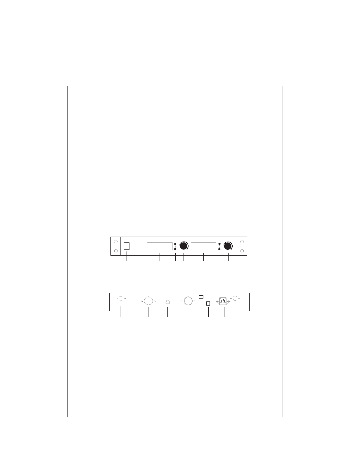
1. Parts Name and Functions
A. Front Panel
POWE
(2)
PROFESSIONAL
UHF
WIRELESSMICROPHONE
R
AF
RF
CH 02: 801 .50MHz
LCD
RECEIVER
CH.A
(3) (5) (3) (5)(4) (4)
MIN
AF
CH 02: 801 .50MHz
MAX
RECEIVER
RF
CH.A
MIN
LCD
MAX
Fig. 1
B. Rear Panel
ANT B ANT A
(1) (6) (7) (6) (8) (1)(9)
OUT B MIX OUT OUT A DC12
(1) Antenna Connector
(2) Power Switch & LED Indicator
(3) Channel Selector
(4) LCD Display
(5) Volume Control
(6) Individual Balanced Audio Output Jacks
(7) Mixed Unbalanced Audio Output Jack
(8) DC 12V Power Input Jack
(9) AC Power Input Jack
(10) Voltage Selector
1
AC:110/220V 50/60Hz
(10)
Fig. 2
Page 3
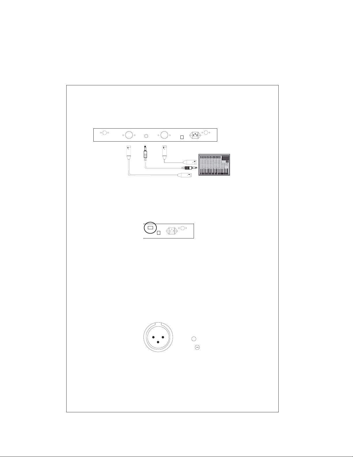
2. Installation of the Receiver
ANT B ANTA
OUT B MIX OUT OUTA DC12
AC: 110V/220V50/60Hz
Fig. 3
1. Power Connection
Connect the AC power cable to the 110/220V AC jack (9) and the other end
into an AC outlet. Check the voltage selector (10) as shown in Fig. 4.
DC12
AC: 110/220V50/60Hz
ANTA
Fig. 4
2. Audio Output Connection:
(A) 1/4” Unbalanced Output: Connect from the unbalanced
output jack (7) of the receiver the input jack of the amplifier,
as shown in Fig. 3.
This outputs the sound from both microphones
to mixer or
a 1/4” cable
together.
(B) XLR Balanced Output: Connect an XLR cable from the balanced
output jack (8) of the receiver to the input jack of the mixer or amplifier,
as shown in Fig.3. There are two individual outputs corresponding to
the two microphones.
12
3
2
1:GND
2:HOT
3:COLD
+
Fig.5
Page 4

3. Extend antennas A & B. Make them perpendicular with the
machine.
4. Push the power switch to turn on the unit.
5. Adjust the volume using the control knobs on the receiver.
Receiver Location
• The receiver should be placed more than 3 ft. above the floor and
3 ft. away from the wall.
• Antennas should be fully extended for best reception.
3. Parts Name And Function (Microphone)
01:08 1.25
MHZ
CH
1 3 45
1. Grill
2. Three position switch (on top).
3. LCD Display
4. Channel Selectors
5. Battery Housing
2
Fig. 6
Page 5

4. Operation of the Microphone
1. Screw the battery box cover counter clockwise. Insert a 9v battery
(check the polarity).
2. Turn on the microphone.
3. The microphone features a three position switch. Place the switch in
Stand By (middle position) to mute the sound without turning off the mic.
Frequency & Channel Listing
Mic B
Mic A
NO. Frequency Range NO. Frequency Range
1
790.75MHz 1 801.25MHz
2 791.15MHz 2 801.55MHz
3 791.55MHz 3 801.85MHz
4 791.95MHz 4 802.15MHz
5 792.35MHz 5 802.45MHz
6 792.75MHz 6 802.75MHz
7 793.15MHz 7 803.05MHz
8 793.55MHz 8 803.35MHz
9 793.95MHz 9 803.65MHz
10 794.35MHz 10 803.95MHz
11 794.75MHz 11 804.25MHz
12 795.15MHz 12 804.55MHz
13 795.55MHz 13 804.85MHz
14 795.95MHz 14 805.15MHz
15 796.35MHz 15 805.45MHz
16 796.75MHz 16 805.75MHz
3
Page 6

5. Troubleshooting
1. Unit does not turn on.
• Make sure the power cable is connected properly.
• Check the fuse.
• Check the voltage selector
2. AF display moves, but there is no sound output.
• Check volume level.
• Check audio cable.
• Check the settings on your amplifier
3. The effective receiving distance decreases.
• Change batteries.
• Check for any devices that may be causing interference.
4. Sound Quality Deteriorates
• Change Batteries.
• Check for any devices that may be causing interference.
• Do not use two machines with the same frequency at the
same time.
Caution:
Do not open the unit. There are no user serviceable parts
inside. Refer service to a qualified technician.
6. Specifications
System Specifications
Carrier Frequency: UHF 790-806MHz
Frequency Stabilization < 30ppm
Dynamic Range: More Than 90dB
Total Harmonic Distortion: Less Than 0.5%
Frequency Response: 40HZ-15KHZ 3dB
Audio Output Level: Unbalanced Out: 0 400mV
......................
................
........................
............
...................
....................
±
±
Balanced Out: 0 ±
–
–
±
200mV
Receiver Specifications
Power Supply: AC 11 220V 50 DC12V
Power Consumption: 5 Watts
S/N Ratio: 90 B
Image & Spurious Rejection: 80d
Border Upon Channel Rejection: 80d
Receiving Sensitivty: 10dBuV(SINAD=30dB)
...........................
....................
................................
..........
......
....................
0 60HZ/ HZ or
>d
>B
>B
<
5
Page 7

Microphone Specifications
Transmitter Power: ......
Modulation Type: .......
Max Deviation: .........
Spurious Emission: ......
Battery Voltage: ........
Battery Life: ...........
Noise Control:..........
60H
0dB
40H 300H 1K 5K 10K 14K 20K 30K
8.5mW
FM, F3F
+25Khz
>40dB (with carrier)
9V
Approx. 8 Hours
Advanced Noise Reduction Circuitry
14KH
Diagram of AF Frequency Response
Attention:
1. For best reception, always maintain line of site between the
transmitter and receiver.
2. Avoid direct sunshine or rain and distance the unit as far as
possible from magnetic fields.
6
 Loading...