

Page 1
Thank you for choosing our productsThank you for choosing our products
Pyle Audio
1600 63rd st , Brooklyn, NY, 11204
(718)236-8000
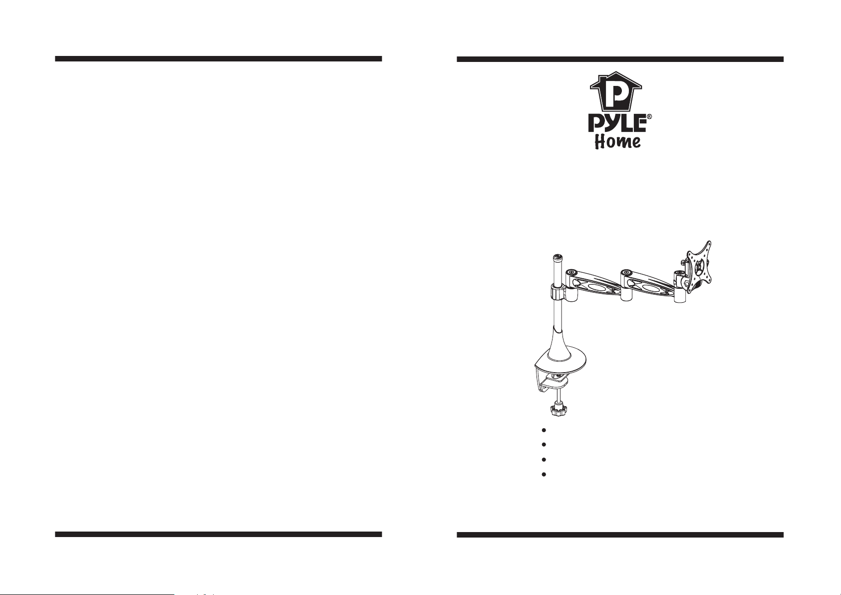
Desktop Bracket
INSTALLATION GUIDE
Item No.:PDLB372Item No.:PDLB372
TV Size Range:10 24""~
Max load capacity 15Kg/33lbs
Integrated Cable management
Angle Adjustable
:
www pyleaudio com..
MADE IN CHINA
-8Important: If don't understand about right install ways,
Important:
please consult to normal installing specialist.
Page 2

Parts:
Display Adjustments
Display Adjustments
Control
Roll Control
6
Roll
Function -Horizontal leveling of the display.
5
3
4
2
Operation -Grasp the sides of the display, and roll it into the desired
position. Then adjusting Roll Tension .
Angle adjusting
Angle adjusting
1 Adjusted with the TV plate .
.
With circumvolve the wall Plate ,TV can adjust in the direction of left
right up and down Vertical Adjusting Angle is from 5° to 20°.
,. -
Level Adjusting Angle is 20°
.
,
Choose the desired angle and turn clockwise the Tension Knob on the right
Hardware List:
ID Description
Qty
Base
1
1
2
3
4
5
6
A
B
C
D
1
A
B
E
C
1
Arm Assembly
Tube Cover
1
TV Plate
1
1
4x4mm Wrench
1
5x5mm Wrench
4
M4×8mm bolt
4
M ×12mm4 bolt
4
M ×8mm5 bolt
4
M5×12mm bolt
4
M5 washer
D
E
of the arm.
2 Adjusted with the arms.
.
With circumvolve the arms, TV can turning to two sides of the base
support until touch the vertical tube. First joint adjusting angle is ±90°,
second is ±90°,third is ±135° .
Vertical height adjustment
Vertical height adjustment
Y
ou can adjust the arm assembly up without any other action, but before
you lower the arm assembly, you should push the plastic button first.
0~110mm vertical height adjustment.
Caution The turning
Caution:
angleisnottoolarge.
:
-520°~ °
±°90
±°90
±135°
Or it may result in
personal injury or
product damage.
Use to adjust the degree
Wrench
of those joints.
Has correctional function: f the wall plate were
I
Tension Knob
20°
Plastic
button
installed imbalance, you can adjust the TV plate
to lever off t
he assembly. Adjust angle is 10
°.
Fig 7
-2-
-7-
Page 3

Step 6 Using Cable Management
Step 6 Using Cable Management
Choose fitting position on the desk.
Step1
Choose fitting position on the desk.Step1
The mount include a cable management function, where cables can be
routed along the length of the arm assembly.
To install cables, you’ll first need to remove the cable covers and set all
parts aside.
Route the cables along one side of the Inner Arm (nearest the wall plate).
With cables in place, loosely secure the Inner Arm cable covers back in place.
Next, route the cables along the opposite side of the Outer Arm. Be sure to
leave slack in the cable where it transitions between two sides of the Arm
Assembly. With cables in position, loosely secure the Outer Arm cable
covers back in place.
Note:
For best system performance, route the AC power cable separately
Note:
from the signal cables.
With all cables in place, pull the display in and out and check that the
arm assembly moves freely, without stretching or damaging the cables,
andthensecurethecablecovers.
Important:
Important:
pressure with your finger.
Cable cover
Fig 5
DO NOT use a hex wrench on the cable covers, only apply
Fig 6
Choose the position that the Base you want installed.
Important: Make sure there is enough space to spread display, considering
the show size.
Step2 Attach
Attach Base
Step2
The thinkness of the table should be smaller than 55mm
We are not responsible for any personal injury or
product damage due to mishandling, incorrect
mounting, incorrect assembly or incorrect use of
this product.
Base
Fig 1
.
.
WARNING
-6-
-3-
Page 4

Step 3
Arm AssembleStep 3 Arm Assemble
Installing the LCD
Step4 Installing the LCD
Remove the T
Adjust the arm assembly to the height then free the Plastic Button.
Recover the tube cover.
ube Cover. Push the Plastic Button down and assemble the Arm.
desired
Plastic Buttom
Arm
Fig 2
According LCD hole's size, deep, position to choose bolts. Using chose
bolts(A-D) and washers(E) to install the LCD on the panel. As shown
in Fig3.
Carefully:
Carefully:
avoiding damage to people and instrument.
Don't use electronics drill to fasten screw
Caution : This Product LCD /Plasma
Caution :
Wall Mount Bracket is intended for use only
with the maximum weights indicated .See
apparatus instructions .Use with products
heavier than the maximum weights indicated
instability causing possible injury .
Step5 Hang the display
Step5 Hang the display
Firstly lift up the TV plate installed the LCD, making the trough on the
arm fit to the trough on it ,according trough to embed the TV plate into
the wall plate.
Once the TV is positioned in place,
fasten the Tighten Bolts on Receiving
Joint clockwise to secure the display
to the Arm Assembly.
Don't force the bolt to LCD hole,
A-D
E
TV Plate
Fig 3
Tighten bolt
-4-
Warning: Some TV require two people
Warning:
to lift, as we are not responsible for any
personal injury or product damage due
to mishandling.
Fig 4
-5-
 Loading...