

Page 1

HD VIDEO SYSTEM
SYSTÈME VIDÉO HAUTE DÉFINITION
HD-V9000
Operating Instructions
Mode d’emploi
Page 2
English
Thank you for buying this Pioneer product. Please read through these operating instructions so you will know how to operate your model
properly. After you have finished reading the instructions, put them away in a safe place for future reference.
In some countries or regions, the shape of the power plug and power outlet may sometimes differ from that shown in the explanatory drawings. However the method of connecting and operating the unit is the same.
IMPORTANT
CAUTION
RISK OF ELECTRIC SHOCK
DO NOT OPEN
The lightning flash with arrowhead symbol,
within an equilateral triangle, is intended to
alert the user to the presence of uninsulated
“dangerous voltage” within the product’s
enclosure that may be of sufficient
magnitude to constitute a risk of electric
shock to persons.
CAUTION:
TO PREVENT THE RISK OF ELECTRIC
SHOCK, DO NOT REMOVE COVER (OR
BACK). NO USER-SERVICEABLE PARTS
INSIDE. REFER SERVICING TO QUALIFIED
SERVICE PERSONNEL.
Information for users on collection and disposal of old equipment and used batteries
The exclamation point within an equilateral
triangle is intended to alert the user to the
presence of important operating and
maintenance (servicing) instructions in the
literature accompanying the appliance.
D3-4-2-1-1_A1_En
Symbol for
equipment
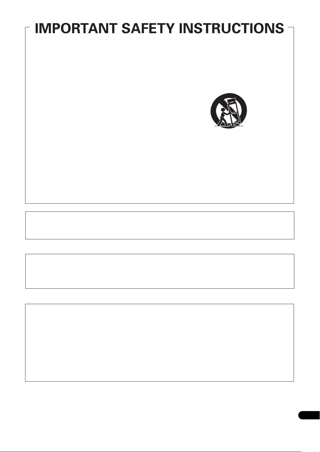
These symbols on the products, packaging, and/or accompanying documents mean
that used electrical and electronic products and batteries should not be mixed with
general household waste.
For proper treatment, recovery and recycling of old products and used batteries,
please take them to applicable collection points in accordance with your national
legislation.
By disposing of these products and batteries correctly, you will help to save valuable
Symbol examples
for batteries
resources and prevent any potential negative effects on human health and the
environment which could otherwise arise from inappropriate waste handling.
For more information about collection and recycling of old products and batteries,
please contact your local municipality, your waste disposal service or the point of sale
where you purchased the items.
These symbols are only valid in the European Union.
For countries outside the European Union:
If you wish to discard these items, please contact your local authorities or dealer and
ask for the correct method of disposal.
Pb
K058a_A1_En
[For USA models]
NOTE:
This equipment has been tested and found to comply with the limits for a Class B digital device, pursuant to Part 15
of the FCC Rules. These limits are designed to provide reasonable protection against harmful interference in a
residential installation. This equipment generates, uses, and can radiate radio frequency energy and, if not installed
and used in accordance with the instructions, may cause harmful interference to radio communications. However,
there is no guarantee that interference will not occur in a particular installation. If this equipment does cause
harmful interference to radio or television reception, which can be determined by turning the equipment off and on,
the user is encouraged to try to correct the interference by one or more of the following measures:
— Reorient or relocate the receiving antenna.
— Increase the separation between the equipment and receiver.
— Connect the equipment into an outlet on a circuit different from that to which the receiver is connected.
— Consult the dealer or an experienced radio/TV technician for help.
D8-10-1-2_A1_En
2
En
Page 3
Read these instructions.
1)
Keep these instructions.
2)
Heed all warnings.
3)
Follow all instructions.
4)
Do not use this apparatus near water.
5)
Clean only with dry cloth.
6)
Do not block any ventilation openings. Install in
7)
Only use attachments/accessories specified by
11)
the manufacturer.
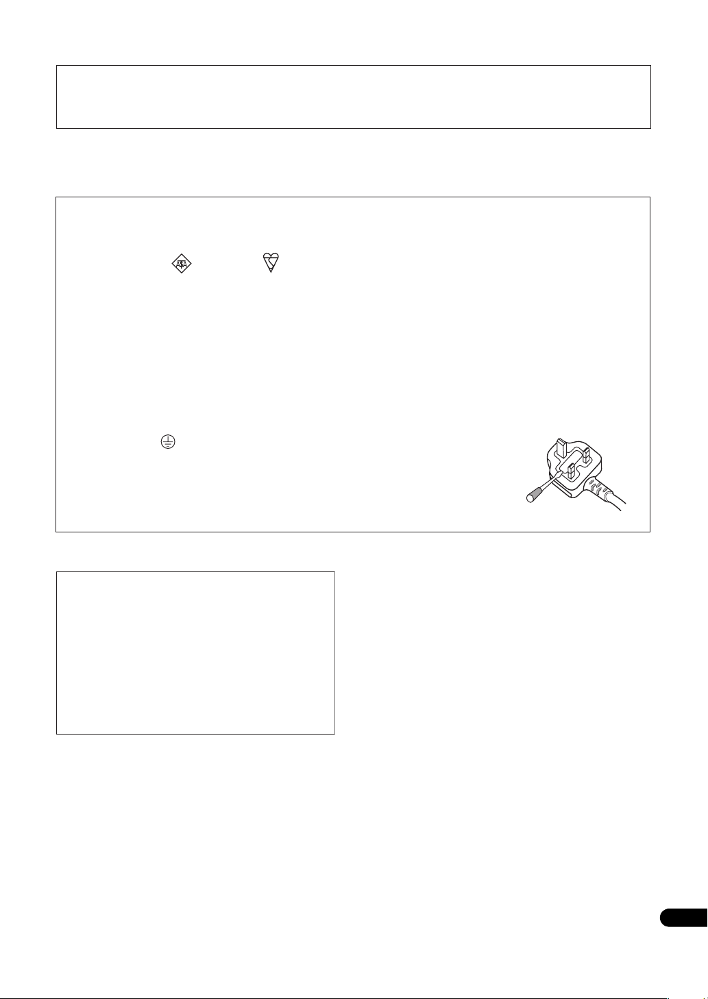
Use only with the cart, stand, tripod, bracket, or
12)
table specified by the manufacturer, or sold with
the apparatus. When a cart is used, use caution
when moving the cart/apparatus combination to
avoid injury from tip-over.
accordance with the manufacturer’s instructions.
Do not install near any heat sources such as
8)
radiators, heat registers, stoves, or other apparatus
(including amplifiers) that produce heat.
Do not defeat the safety purpose of the polarized
9)
or grounding-type plug. A polarized plug has two
blades with one wider than the other. A
grounding type plug has two blades and a third
grounding prong. The wide blade or the third
prong are provided for your safety. If the provided
plug does not fit into your outlet, consult an
electrician for replacement of the obsolete outlet.
Protect the power cord from being walked on or
10)
pinched particularly at plugs, convenience
receptacles, and the point where they exit from
the apparatus.
Information to User
Alterations or modifications carried out without appropriate authorization may invalidate the user’s right to operate
the equipment.
Unplug this apparatus during lightning storms
13)
or when unused for long periods of time.
Refer all servicing to qualified service personnel.
14)
Servicing is required when the apparatus has
been damaged in any way, such as power-supply
cord or plug is damaged, liquid has been spilled
or objects have fallen into the apparatus, the
apparatus has been exposed to rain or moisture,
does not operate normally, or has been dropped.
P1-4-2-2_En
D8-10-2_A1_En
[For USA models]
CAUTION
This product satisfies FCC regulations when shielded cables and connectors are used to connect the unit to other
equipment. To prevent electromagnetic interference with electric appliances such as radios and televisions, use
shielded cables and connectors for connections.
D8-10-3a_A1_En
[For USA models]
FEDERAL COMMUNICATIONS COMMISSION DECLARATION OF CONFORMITY
This device complies with part 15 of the FCC Rules. Operation is subject to the following two conditions: (1) This
device may not cause harmful interference, and (2) this device must accept any interference received, including
interference that may cause undesired operation.
Product Name: HD VIDEO SYSTEM
Model Number: HD-V9000
Responsible Party Name: PIONEER ELECTRONICS (USA) INC.
SERVICE SUPPORT DIVISION
Address: 1925 E. DOMINGUEZ ST. LONG BEACH, CA 90810-1003, U.S.A.
Phone: 1-800-421-1404
URL: http://www.pioneerelectronics.com
D8-10-4*_C1_En
3
En
Page 4

WARNING
This equipment is not waterproof. To prevent a fire or
shock hazard, do not place any container filled with
liquid near this equipment (such as a vase or flower
pot) or expose it to dripping, splashing, rain or
moisture.
D3-4-2-1-3_A1_En
WARNING
Before plugging in for the first time, read the following
section carefully.
The voltage of the available power supply differs
according to country or region. Be sure that the
power supply voltage of the area where this unit
will be used meets the required voltage (e.g., 230 V
or 120 V) written on the rear panel.
D3-4-2-1-4*_A1_En
WARNING
This product equipped with a three-wire grounding
(earthed) plug - a plug that has a third (grounding) pin.
This plug only fits a grounding-type power outlet. If you
are unable to insert the plug into an outlet, contact a
licensed electrician to replace the outlet with a properly
grounded one. Do not defeat the safety purpose of the
grounding plug.
D3-4-2-1-6_A1_En
WARNING
To prevent a fire hazard, do not place any naked flame
sources (such as a lighted candle) on the equipment.
D3-4-2-1-7a_A1_En
VENTILATION CAUTION
When installing this unit, make sure to leave space
around the unit for ventilation to improve heat radiation
(at least 5 cm at top, 5 cm at rear, and 5 cm at each
side).
WARNING
Slots and openings in the cabinet are provided for
ventilation to ensure reliable operation of the product,
and to protect it from overheating. To prevent fire
hazard, the openings should never be blocked or
covered with items (such as newspapers, table-cloths,
curtains) or by operating the equipment on thick carpet
or a bed.
D3-4-2-1-7b*_A1_En
Operating Environment
Operating environment temperature and humidity:
0 °C to +45 °C (+32 °F to +113 °F); less than 85 %RH
(cooling vents not blocked)
Do not install this unit in a poorly ventilated area, or in
locations exposed to high humidity or direct sunlight (or
strong artificial light)
D3-4-2-1-7c*_A1_En
If the AC plug of this unit does not match the AC
outlet you want to use, the plug must be removed
and appropriate one fitted. Replacement and
mounting of an AC plug on the power supply cord of
this unit should be performed only by qualified
service personnel. If connected to an AC outlet, the
cut-off plug can cause severe electrical shock. Make
sure it is properly disposed of after removal.
The equipment should be disconnected by removing
the mains plug from the wall socket when left unused
for a long period of time (for example, when on
vacation).
D3-4-2-2-1a_A1_En
CAUTION
The STANDBY/ON switch on this unit will not
completely shut off all power from the AC outlet.
Since the power cord serves as the main disconnect
device for the unit, you will need to unplug it from the
AC outlet to shut down all power. Therefore, make
sure the unit has been installed so that the power
cord can be easily unplugged from the AC outlet in
case of an accident. To avoid fire hazard, the power
cord should also be unplugged from the AC outlet
when left unused for a long period of time (for
example, when on vacation).
D3-4-2-2-2a*_A1_En
POWER-CORD CAUTION
Handle the power cord by the plug. Do not pull out the
plug by tugging the cord and never touch the power
cord when your hands are wet as this could cause a
short circuit or electric shock. Do not place the unit, a
piece of furniture, etc., on the power cord, or pinch the
cord. Never make a knot in the cord or tie it with other
cords. The power cords should be routed such that they
are not likely to be stepped on. A damaged power cord
can cause a fire or give you an electrical shock. Check
the power cord once in a while. When you find it
damaged, ask your nearest PIONEER authorized
service center or your dealer for a replacement.
S002*_A1_En
[For USA models]
WARNING: Handling the cord on this product or
cords associated with accessories sold with the
product may expose you to chemicals listed on
proposition 65 known to the State of California and
other governmental entities to cause cancer and
birth defect or other reproductive harm.
Wash hands after handling.
D36-P5_B1_En
[For Canada models]
This Class B digital apparatus complies with
Canadian ICES-003.
D8-10-1-3_A1_En
4
En
Page 5
[For USA models]
IMPORTANT NOTICE
THE MODEL NUMBER AND SERIAL NUMBER OF THIS EQUIPMENT ARE ON THE REAR OR BOTTOM.
RECORD THESE NUMBERS ON YOUR ENCLOSED WARRANTY CARD AND KEEP IN A SAFE PLACE FOR FUTURE
REFERENCE.
D36-AP9-1_A1_En
[For UK models]
Replacement and mounting of an AC plug on the power supply cord of this unit should be performed only by qualified
service personnel.
IMPORTANT: THE MOULDED PLUG
This appliance is supplied with a moulded three pin mains plug for your safety and convenience. A 13 amp fuse is fitted in this plug. Should
the fuse need to be replaced, please ensure that the replacement fuse has a rating of 13 amps and that it is approved by ASTA or BSI to
BS1362.
Check for the ASTA mark or the BSI mark on the body of the fuse.
If the plug contains a removable fuse cover, you must ensure that it is refitted when the fuse is replaced. If you lose the fuse cover the plug
must not be used until a replacement cover is obtained. A replacement fuse cover can be obtained from your local dealer.
If the fitted moulded plug is unsuitable for your socket outlet, then the fuse shall be removed and the plug cut off and disposed of
safely. There is a danger of severe electrical shock if the cut off plug is inserted into any 13 amp socket.
If a new plug is to be fitted, please observe the wiring code as shown below. If in any doubt, please consult a qualified electrician.
WARNING: THIS APPARATUS MUST BE EARTHED.
IMPORTANT: The wires in this mains lead are coloured in accordance with the following code:
As the colours of the wires in the mains lead of this appliance may not correspond with the coloured markings identifying the terminals in
your plug, proceed as follows;
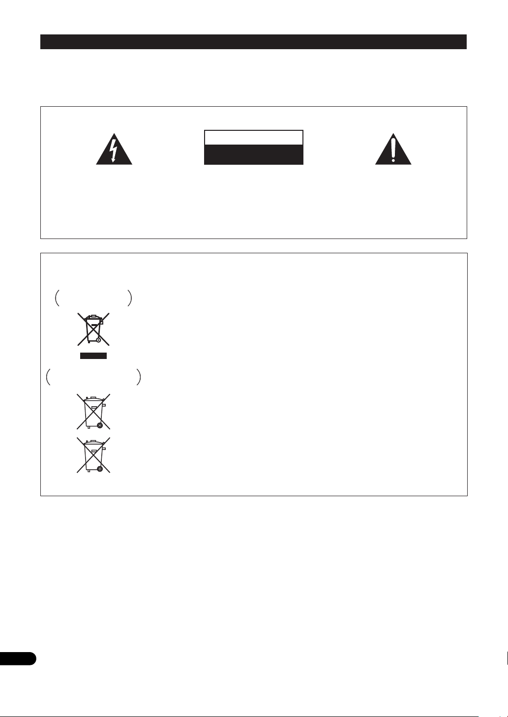
The wire which is coloured GREEN-AND-YELLOW must be connected to the terminal in the plug which is marked with the letter E or by
the earth symbol or coloured GREEN or GREEN-AND-YELLOW.
The wire which is coloured BLUE must be connected to the terminal which is marked with the
letter N or coloured BLACK.
The wire which is coloured BROWN must be connected to the terminal which is marked with the
letter L or coloured RED.
How to replace the fuse: Open the fuse compartment with a screwdriver and replace the fuse.
Green & Yellow : Earth Blue : Neutral Brown : Live
D3-4-2-1-2-1*_A1_En
[For UK models]
Compliance with these directives implies conformity
to the following European standards
( EN 60065 : Product Safety
( EN 55103-1: Electromagnetic Interference
(Emission)
( EN 55103-2: Electromagnetic Susceptibility
(Immunity)
This product is intended for use in the following
electromagnetic environment(s):
E2 (commercial and light industrial)
D44-9-7-1*_A1_En
5
En
Page 6
Français
Nous vous remercions d’avoir acquis un produit Pioneer. Veuillez lire attentivement ce mode d’emploi afin de connaître la manière
d’utiliser l’appareil comme il convient. Cela fait, conservez le mode d’emploi de façon à pouvoir vous y référer en cas de nécessité.
Dans certains pays ou certaines régions, la forme de la fiche d’alimentation et de la prise d’alimentation peut différer de celle qui figure sur
les schémas, mais les branchements et le fonctionnement de l’appareil restent les mêmes.
IMPORTANT
ATTENTION
DANGER D´ELECTROCUTION
NE PAS OUVRIR
Ce symbole de l’éclair, placé dans un
triangle équilatéral, a pour but d’attirer
l’attention de l’utilisateur sur la présence, à
l’intérieur du coffret de l’appareil, de
“tensions dangereuses” non isolées d’une
grandeur suffisante pour représenter un
risque d’électrocution pour les êtres
humains.
ATTENTION :
POUR ÉVITER TOUT RISQUE
D’ÉLECTROCUTION, NE PAS ENLEVER LE
COUVERCLE (NI LE PANNEAU ARRIÈRE).
AUCUNE PIÈCE RÉPARABLE PAR
L’UTILISATEUR NE SE TROUVE À
L’INTÉRIEUR. CONFIER TOUT ENTRETIEN À
UN PERSONNEL QUALIFIÉ UNIQUEMENT.
Information à destination des utilisateurs sur la collecte et l’élimination des
équipements et batteries usagés
Marquage pour les
équipements
Exemples de marquage
pour les batteries
Pb
Ces symboles qui figurent sur les produits, les emballages et/ou les documents
d’accompagnement signifient que les équipements électriques et électroniques et
batteries usagés ne doivent pas être jetés avec les déchets ménagers et font l’objet
d’une collecte sélective.
Pour assurer l’enlèvement et le traitement appropriés des produits et batteries
usagés, merci de les retourner dans les points de collecte sélective habilités
conformément à la législation locale en vigueur.
En respectant les circuits de collecte sélective mis en place pour ces produits, vous
contribuerez à économiser des ressources précieuses et à prévenir les impacts
négatifs éventuels sur la santé humaine et l’environnement qui pourraient résulter
d’une mauvaise gestion des déchets.
Pour plus d’information sur la collecte et le traitement des produits et batteries
usagés, veuillez contacter votre municipalité, votre service de gestion des déchets
ou le point de vente chez qui vous avez acheté ces produits.
Ces symboles ne sont valables que dans les pays de l’Union Européenne.
Pour les pays n’appartenant pas à l’Union Européenne :
Si vous souhaitez jeter ces articles, veuillez contacter les autorités ou revendeurs
locaux pour connaître les méthodes d’élimination appropriées.
Ce point d’exclamation, placé dans un
triangle équilatéral, a pour but d’attirer
l’attention de l’utilisateur sur la présence,
dans les documents qui accompagnent
l’appareil, d’explications importantes du
point de vue de l’exploitation ou de
l’entretien.
D3-4-2-1-1_A1_Fr
K058a_A1_Fr
6
Fr
Page 7
P1-4-2-2_Fr
[Pour modèle du Canada]
Cet appareil numérique de la Classe B est conforme
à la norme NMB-003 du Canada.
D8-10-1-3_A1_Fr
[Pour les modèles UK]
La conformité à ces directives implique la conformité
aux normes européennes suivantes :
&EN 60065 : Sécurité du produit
& EN 55103-1: Interférences électromagnétiques
(Émission)
& EN 55103-2: Susceptibilité électromagnétique
(Immunité)
Ce produit est destiné à être utilisé dans les
environnements électromagnétiques suivants :
E2 (commercial et industriel léger)
D44-9-7-1*_A1_Fr
7
Fr
Page 8

AVERTISSEMENT
Cet appareil n’est pas étanche. Pour éviter les risques
d’incendie et de décharge électrique, ne placez près de
lui un récipient rempli d’eau, tel qu’un vase ou un pot
de fleurs, et ne l’exposez pas à des gouttes d’eau, des
éclaboussures, de la pluie ou de l’humidité.
D3-4-2-1-3_A1_Fr
AVERTISSEMENT
Avant de brancher l’appareil pour la première, lisez
attentivement la section suivante.
La tension de l’alimentation électrique disponible
varie selon le pays ou la région. Assurez-vous que
la tension du secteur de la région où l’appareil sera
utilisé correspond à la tension requise (par ex. 230
V ou 120 V), indiquée sur le panneau arrière.
D3-4-2-1-4*_A1_Fr
AVERTISSEMENT
Cet appareil est muni d’une fiche de mise à la terre
(masse) à trois fils. Comme la fiche présente une
troisième broche (de terre), elle ne peut se brancher
que sur une prise de courant, prévue pour une mise à
la terre. Si vous n’arrivez pas à insérer la fiche dans la
prise de courant, contactez un électricien qualifié pour
faire remplacer la prise par une qui soit mise à la terre.
N’annulez pas la fonction de sécurité que procure cette
fiche de mise à la terre.
D3-4-2-1-6_A1_Fr
AVERTISSEMENT
Pour éviter les risques d’incendie, ne placez aucune
flamme nue (telle qu’une bougie allumée) sur
l’appareil.
D3-4-2-1-7a_A1_Fr
PRÉCAUTION DE VENTILATION
Lors de l’installation de l’appareil, veillez à laisser un
espace suffisant autour de ses parois de manière à
améliorer la dissipation de chaleur (au moins 5 cm sur
le dessus, 5 cm à l’arrière et 5 cm de chaque côté).
AVERTISSEMENT
Les fentes et ouvertures du coffret sont prévues pour la
ventilation, pour assurer un fonctionnement stable de
l’appareil et pour éviter sa surchauffe. Pour éviter les
risques d’incendie, ne bouchez jamais les ouvertures et
ne les recouvrez pas d’objets, tels que journaux, nappes
ou rideaux, et n’utilisez pas l’appareil posé sur un tapis
épais ou un lit.
D3-4-2-1-7b*_A1_Fr
Si la fiche d’alimentation secteur de cet appareil ne
convient pas à la prise secteur à utiliser, la fiche doit
être remplacée par une appropriée. Ce
remplacement et la fixation d’une fiche secteur sur le
cordon d’alimentation de cet appareil doivent être
effectués par un personnel de service qualifié. En cas
de branchement sur une prise secteur, la fiche de
coupure peut provoquer une sérieuse décharge
électrique. Assurez-vous qu’elle est éliminée
correctement après sa dépose.
L’appareil doit être déconnecté en débranchant sa fiche
secteur au niveau de la prise murale si vous prévoyez
une période prolongée de non utilisation (par exemple
avant un départ en vacances).
D3-4-2-2-1a_A1_Fr
ATTENTION
L’interrupteur STANDBY/ON de cet appareil ne
coupe pas complètement celui-ci de sa prise secteur.
Comme le cordon d’alimentation fait office de
dispositif de déconnexion du secteur, il devra être
débranché au niveau de la prise secteur pour que
l’appareil soit complètement hors tension. Par
conséquent, veillez à installer l’appareil de telle
manière que son cordon d’alimentation puisse être
facilement débranché de la prise secteur en cas
d’accident. Pour éviter tout risque d’incendie, le
cordon d’alimentation sera débranché au niveau de
la prise secteur si vous prévoyez une période
prolongée de non utilisation (par exemple avant un
départ en vacances).
D3-4-2-2-2a*_A1_Fr
NOTE IMPORTANTE SUR LE CABLE
D’ALIMENTATION
Tenir le câble d’alimentation par la fiche. Ne pas
débrancher la prise en tirant sur le câble et ne pas
toucher le câble avec les mains mouillées. Cela risque
de provoquer un court-circuit ou un choc électrique. Ne
pas poser l’appareil ou un meuble sur le câble. Ne pas
pincer le câble. Ne pas faire de noeud avec le câble ou
l’attacher à d’autres câbles. Les câbles d’alimentation
doivent être posés de façon à ne pas être écrasés. Un
câble abîmé peut provoquer un risque d’incendie ou un
choc électrique. Vérifier le câble d’alimentation de
temps en temps. Contacter le service après-vente
PIONEER le plus proche ou le revendeur pour un
remplacement.
S002*_A1_Fr
Milieu de fonctionnement
Température et humidité du milieu de fonctionnement :
De 0 °C à +45 °C (de +32 °F à +113 °F) ; Humidité
relative inférieure à 85 % (orifices de ventilation non
obstrués)
N’installez pas l’appareil dans un endroit mal ventilé ou
un lieu soumis à une forte humidité ou en plein soleil
(ou à une forte lumière artificielle).
8
Fr
D3-4-2-1-7c*_A1_Fr
Page 9

9
Fr
Page 10

Deutsch
Vielen Dank, dass Sie sich für dieses Pioneer-Produkt entschieden haben. Bitte lesen Sie diese Bedienungsanleitung gründlich durch, um
sich mit der Bedienung des Geräts vertraut zu machen. Nachdem Sie die Bedienungsanleitung gelesen haben, legen Sie sie griffbereit zum
Nachschlagen ab.
In manchen Ländern oder Verkaufsgebieten weichen die Ausführungenvon Netzstecker oder Netzsteckdose u.U. von den in den
Abbildungengezeigten ab; die Anschluß- und Bedienungsverfahren des Gerätes sind jedoch gleich.
WICHTIG
CAUTION
RISK OF ELECTRIC SHOCK
DO NOT OPEN
Das Blitzsymbol in einem Dreieck weist den
Benutzer darauf hin, dass eine
Berührungsgefahr mit nicht isolierten Teilen
im Geräteinneren, die eine gefährliche
Spannung führen, besteht. Die Spannung
kann so hoch sein, dass sie die Gefahr eines
elektrischen Schlages birgt.
ACHTUNG:
UM SICH NICHT DER GEFAHR EINES
ELEKTRISCHEN SCHLAGES
AUSZUSETZEN, DÜRFEN SIE NICHT DEN
DECKEL (ODER DIE RÜCKSEITE)
ENTFERNEN. IM GERÄTEINNEREN
BEFINDEN SICH KEINE VOM BENUTZER
REPARIERBAREN TEILE. ÜBERLASSEN SIE
REPARATUREN DEM QUALIFIZIERTEN
KUNDENDIENST.
Informationen für Anwender zur Sammlung und Entsorgung von Altgeräten und
gebrauchten Batterien
Symbol für
Geräte
Symbolbeispiele
für Batterien
Pb
Diese Symbole auf den Produkten, der Verpackung und/oder Begleitdokumenten
bedeuten, dass gebrauchte elektrische und elektronische Produkte und Batterien
nicht über den Haushaltsmüll entsorgt werden dürfen.
Zur richtigen Handhabung, Rückgewinnung und Wiederverwertung von Altprodukten
und gebrauchten Batterien bringen Sie diese bitte zu den gemäß der nationalen
Gesetzgebung dafür zuständigen Sammelstellen.
Mit der korrekten Entsorgung dieser Produkte und Batterien helfen Sie dabei,
wertvolle Ressourcen zu schonen und vermeiden mögliche negative Auswirkungen
auf die Gesundheit und die Umwelt, die durch eine unsachgemäße Behandlung des
Abfalls entstehen könnten.
Weitere Informationen zur Sammlung und Wiederverwertung von Altprodukten und
Batterien erhalten Sie von Ihrer örtlichen Gemeindeverwaltung, Ihrem Müllentsorger
oder dem Verkaufsort, an dem Sie die Waren erworben haben.
Diese Symbole gelten ausschließlich in der Europäischen Union.
Für Länder außerhalb der Europäischen Union:
Wenn Sie diese Gegenstände entsorgen wollen, wenden Sie sich bitte an Ihre
lokalen Behörden oder Händler und fragen Sie dort nach der korrekten
Entsorungsweise.
Ein Ausrufezeichen in einem Dreieck weist
den Benutzer auf wichtige Bedienungs- und
Wartungsanweisungen in den Dokumenten
hin, die dem Gerät beiliegen.
D3-4-2-1-1_A1_De
[Für Großbritannien-Modelle]
Die Erfüllung dieser Richtlinien setzt Konformität mit
den folgenden europäischen Normen voraus
,EN 60065 : Produktsicherheit
, EN 55103-1: Elektromagnetische Störungen
(Emission)
, EN 55103-2: Elektromagnetische Störanfälligkeit
(Störfestigkeit)
Dieses Produkt ist zur Verwendung in den folgenden
elektromagnetischen Störumgebungen gedacht:
10
E2 (Gewerbe- und Leichtindustriegebiete)
De
K058a_A1_De
D44-9-7-1*_A1_De
Page 11

WARNUNG
Dieses Gerät ist nicht wasserdicht. Zur Vermeidung der
Gefahr von Brand und Stromschlag keine Behälter mit
Flüssigkeiten (z.B. Blumenvasen und -töpfe) in die
Nähe des Gerätes bringen und dieses vor Tropfwasser,
Spritzwasser, Regen und Nässe schützen.
D3-4-2-1-3_A1_De
WARNUNG
Vor dem erstmaligen Anschluss des Gerätes an das
Stromnetz bitte den folgenden Hinweis sorgfältig
beachten.
Die Netzspannung ist je nach Land verschieden.
Vor der Inbetriebnahme des Gerätes sicherstellen,
dass die örtliche Netzspannung mit der auf dem
Typenschild an der Rückwand des Gerätes
angegebenen Nennspannung (z.B. 230 V oder 120
V) übereinstimmt.
D3-4-2-1-4*_A1_De
WARNUNG
Das Netzkabel dieses Gerätes ist mit einem dreipoligen
(einschließlich Erdungsstift) Netzstecker ausgestattet,
der ausschließlich für den Anschluss an eine (geerdete)
Schuko-Steckdose vorgesehen ist. Falls der Netzstecker
aufgrund einer abweichenden Ausführung nicht an die
Netzsteckdose angeschlossen werden kann, muss ein
Elektriker mit der Installation einer vorschriftsmäßigen
Netzsteckdose beauftragt werden. Beim Erdungsstift
handelt es sich um eine Sicherheitsvorrichtung, die auf
keinen Fall umgangen oder außer Kraft gesetzt werden
darf.
D3-4-2-1-6_A1_De
Falls der Netzstecker des Netzkabels dieses Gerätes
nicht in die Zusatzsteckdose einer anderen
Komponente passt, muss er gegen einen Netzstecker
der geeigneten Ausführung ausgewechselt werden.
Ein derartiger Austausch des Netzsteckers muss vom
Kundendienstpersonal vorgenommen werden. Wenn
der vom Netzkabel abgeschnittene ursprüngliche
Netzstecker in eine Netzsteckdose eingesteckt wird,
besteht akute Stromschlaggefahr! Daher ist
unbedingt dafür zu sorgen, dass der abgeschnittene
Netzstecker sofort vorschriftsmäßig entsorgt wird.
Vor einem längeren Nichtgebrauch des Gerätes,
beispielsweise während des Urlaubs, sollte der
Netzstecker aus der Netzsteckdose gezogen werden,
um das Gerät vollständig vom Netz zu trennen.
D3-4-2-2-1a_A1_De
ACHTUNG
Der STANDBY/ON-Schalter dieses Gerätes trennt
das Gerät nicht vollständig vom Stromnetz. Um das
Gerät vollständig vom Netz zu trennen, muss der
Netzstecker aus der Netzsteckdose gezogen werden.
Daher sollte das Gerät so aufgestellt werden, dass
stets ein unbehinderter Zugang zur Netzsteckdose
gewährleistet ist, damit der Netzstecker in einer
Notsituation sofort abgezogen werden kann. Um
Brandgefahr auszuschließen, sollte der Netzstecker
vor einem längeren Nichtgebrauch des Gerätes,
beispielsweise während des Urlaubs, grundsätzlich
von der Netzsteckdose getrennt werden.
D3-4-2-2-2a*_A1_De
WARNUNG
Keine Quellen offener Flammen (z.B. eine brennende
Kerze) auf dieses Gerät stellen.
D3-4-2-1-7a_A1_De
VORSICHTSHINWEIS ZUR BELÜFTUNG
Bei der Aufstellung dieses Gerätes muss für einen
ausreichenden Freiraum gesorgt werden, um eine
einwandfreie Wärmeabfuhr zu gewährleisten
(mindestens 5 cm oberhalb des Gerätes, 5 cm hinter
dem Gerät und jeweils 5 cm an der Seite des Gerätes).
WARNUNG
Im Gerätegehäuse sind Ventilationsschlitze und andere
Öffnungen vorgesehen, die dazu dienen, eine
Überhitzung des Gerätes zu verhindern und einen
zuverlässigen Betrieb zu gewährleisten. Um
Brandgefahr auszuschließen, dürfen diese Öffnungen
auf keinen Fall blockiert oder mit Gegenständen (z.B.
Zeitungen, Tischdecken und Gardinen) abgedeckt
werden, und das Gerät darf beim Betrieb nicht auf
einem dicken Teppich oder Bett aufgestellt sein.
D3-4-2-1-7b*_A1_De
Betriebsumgebung
Betriebstemperatur und Betriebsluftfeuchtigkeit:
0 °C bis +45 °C, 85 % rel. Feuchte max.
(Ventilationsschlitze nicht blockiert)
Eine Aufstellung dieses Gerät an einem unzureichend
belüfteten, sehr feuchten oder heißen Ort ist zu
vermeiden, und das Gerät darf weder direkter
Sonneneinstrahlung noch starken Kunstlichtquellen
ausgesetzt werden.
D3-4-2-1-7c*_A1_De
VORSICHT MIT DEM NETZKABEL
Fassen Sie das Netzkabel immer am Stecker. Ziehen Sie
nicht am Kabel selbst, und fassen Sie das Netzkabel
niemals mit nassen Händen an, da dies einen
Kurzschluss oder elektrischen Schlag verursachen
kann. Stellen Sie nicht das Gerät, Möbelstücke o.ä. auf
das Netzkabel; sehen Sie auch zu, dass es nicht
eingeklemmt wird. Machen Sie niemals einen Knoten
in das Netzkabel, und binden Sie es nicht mit anderen
Kabeln. Das Netzkabel sollte so gelegt werden, dass
niemand darauf tritt. Ein beschädigtes Netzkabel kann
einen Brand oder elektrischen Schlag verursachen.
Prüfen Sie das Netzkabel von Zeit zu Zeit. Sollte es
beschädigt sein, wenden Sie sich an Ihre nächste
autorisierte PIONEER-Kundendienststelle oder Ihren
Händler, um es zu ersetzen.
S002*_A1_De
11
De
Page 12

Italiano
Vi ringraziamo per avere acquistato questo prodotto Pioneer. Vi preghiamo di leggere queste queste istruzioni per l’uso in modo da sapere
usare correttamente il proprio modello. Dopo aver letto queste istruzioni, riporle in un luogo sicuro per poterle consultare di nuovo al
momento del bisogno.
I modelli disponibili in alcuni paesi o regioni possono avere la forma della spina del cavo d’alimentazione e della presa ausiliaria di corrente
diversa daquella mostrata nelle illustrazioni, ma il loro modo di collegamento e funzionamento è lo stesso.
IMPORTANTE
CAUTION
RISK OF ELECTRIC SHOCK
DO NOT OPEN
Il simbolo del lampo con terminale a forma
di freccia situato all’interno di un triangolo
equilatero serve ad avvisare l’utilizzatore
della presenza di una “tensione pericolosa”
non isolata nella struttura del prodotto che
potrebbe essere di un’intensità tale da
provocare scosse elettriche all’utilizzatore.
ATTENZIONE:
PER EVITARE IL RISCHIO DI SCOSSE
ELETTRICHE, NON RIMUOVERE IL
COPERCHIO (O IL RETRO). NON CI SONO
PARTI INTERNE LA CUI MANUTENZIONE
POSSA ESSERE EFFETTUATA
DALL’UTENTE. IN CASO DI NECESSITÀ,
RIVOLGERSI ESCLUSIVAMENTE A
PERSONALE DI SERVIZIO QUALIFICATO.
Informazioni per gli utilizzatori finali sulla raccolta e lo smaltimento di vecchi
dispositivi e batterie esauste
Simbolo per
il prodotto
Esempi di simboli
per le batterie
Pb
Questi simboli sui prodotti, confezioni, e/o documenti allegati significano che vecchi
prodotti elettrici ed elettronici e batterie esauste non devono essere mischiati ai rifiuti
urbani indifferenziati.
Per l’appropriato trattamento, recupero e riciclaggio di vecchi prodotti e batterie
esauste, fate riferimento ai punti di raccolta autorizzati in conformità alla vostra
legislazione nazionale.
Con il corretto smaltimento di questi prodotti e delle batterie, aiuterai a salvaguardare
preziose risorse e prevenire i potenziali effetti negativi sull’ambiente e sulla salute
umana che altrimenti potrebbero sorgere da una inappropriata gestione dei rifiuti.
Per maggiori informazioni sulla raccolta e il riciclaggio di vecchi prodotti e batterie
esauste, contattate il vostro Comune, il Servizio di raccolta o il punto vendita dove
avete acquistato l’articolo.
Questi simboli sono validi solo nell’Unione Europea.
Per i paesi al di fuori dell’unione Europea:
Se volete liberarvi questi oggetti, contattate le vostre autorità locali o il punto vendita
per il corretto metodo di smaltimento.
Il punto esclamativo in un triangolo
equilatero serve ad avvisare l’utilizzatore
della presenza di importanti istruzioni di
funzionamento e manutenzione riportate nel
libretto allegato al prodotto.
D3-4-2-1-1_A1_It
[Per i modelli per la GB]
La conformità con queste direttive implica quella con i
seguenti standard europei:
(EN 60065 : Sicurezza dei prodotti
( EN 55103-1: Interferenze elettromagnetiche
(emissioni)
( EN 55103-2: suscettibilità elettromagnetica
(immunità)
Questo prodotto è inteso per l’uso nei seguenti
ambienti elettromagnetici:
E2 (commerciali e dell’industria leggera)
12
It
K058a_A1_It
D44-9-7-1*_A1_It
Page 13

ATTENZIONE
Questo apparecchio non è impermeabile. Per prevenire
pericoli di incendi o folgorazioni, non posizionare nelle
vicinanze di questo apparecchio contenitori pieni di
liquidi (quali vasi da fiori, o simili), e non esporre
l’apparecchio a sgocciolii, schizzi, pioggia o umidità.
D3-4-2-1-3_A1_It
ATTENZIONE
Prima di collegare per la prima volta l’apparecchio alla
sorgente di alimentazione leggere attentamente la
sezione che segue.
La tensione della sorgente di elettricità differisce
da Paese a Paese e da regione a regione. Verificare
che la tensione di rete della zona in cui si intende
utilizzare l’apparecchio sia quella corretta, come
indicato sul pannello posteriore dell’apparecchio
stesso (ad es.: 230 V o 120 V).
D3-4-2-1-4*_A1_It
Se la spina del cavo di alimentazione di questo
apparecchio non si adatta alla presa di corrente
alternata di rete nella quale si intende inserire la
spina stessa, questa deve essere sostituita con una
adatta allo scopo. La sostituzione della spina del cavo
di alimentazione deve essere effettuata solamente da
personale di servizio qualificato. Dopo la sostituzione,
la vecchia spina, tagliata dal cavo di alimentazione,
deve essere adeguatamente eliminata per evitare
possibili scosse o folgorazioni dovute all’accidentale
inserimento della spina stessa in una presa di
corrente sotto tensione.
Se si pensa di non utilizzare l’apparecchio per un
relativamente lungo periodo di tempo (ad esempio,
durante una vacanza), staccare la spina del cavo di
alimentazione dalla presa di corrente alternata di
rete.
D3-4-2-2-1a_A1_It
ATTENZIONE
Questo apparecchio è dotato di una spina con messa a
terra, cioè di una spina con un terzo spinotto (per la
messa a terra). Questo tipo di spine si inserisce
solamente in prese di corrente dello stesso tipo, cioè
con attacco per messa a terra. Se non si riesce ad
inserire la spina nella presa di corrente di casa,
rivolgersi ad un elettricista qualificato per far sostituire
la presa alla parete con una dotata di attacco per la
messa a terra. Non annullare la scopo di sicurezza della
spina con messa a terra.
D3-4-2-1-6_A1_It
ATTENZIONE
Per evitare il pericolo di incendi, non posizionare
sull’apparecchio dispositivi con fiamme vive (ad
esempio una candela accesa, o simili).
D3-4-2-1-7a_A1_It
AVVERTENZA PER LA VENTILAZIONE
Installare l’apparecchio avendo cura di lasciare un
certo spazio all’intorno dello stesso per consentire una
adeguata circolazione dell’aria e migliorare la
dispersione del calore (almeno 5 cm sulla parte
superiore, 5 cm sul retro, e 5 cm su ciascuno dei lati).
ATTENZIONE
L’apparecchio è dotato di un certo numero di fessure e
di aperture per la ventilazione, allo scopo di garantirne
un funzionamento affidabile, e per proteggerlo dal
surriscaldamento. Per prevenire possibili pericoli di
incendi le aperture non devono mai venire bloccate o
coperte con oggetti vari (quali giornali, tovaglie, tende o
tendaggi, ecc.), e l’apparecchio non deve essere
utilizzato appoggiandolo su tappeti spessi o sul letto.
D3-4-2-1-7b*_A1_It
Condizioni ambientali di funzionamento
Gamma ideale della temperatura ed umidità
dell’ambiente di funzionamento:
da 0 °C a +45 °C, umidità relativa inferiore all‘85 %
(fessure di ventilazione non bloccate)
Non installare l’apparecchio in luoghi poco ventilati, o
in luoghi esposti ad alte umidità o alla diretta luce del
sole (o a sorgenti di luce artificiale molto forti).
D3-4-2-1-7c*_A1_It
AVVERTENZA
L’interruttore principale (STANDBY/ON)
dell’apparecchio non stacca completamente il flusso
di corrente elettrica dalla presa di corrente alternata
di rete. Dal momento che il cavo di alimentazione
costituisce l’unico dispositivo di distacco
dell’apparecchio dalla sorgente di alimentazione, il
cavo stesso deve essere staccato dalla presa di
corrente alternata di rete per sospendere
completamente qualsiasi flusso di corrente.
Verificare quindi che l’apparecchio sia stato installato
in modo da poter procedere con facilità al distacco
del cavo di alimentazione dalla presa di corrente, in
caso di necessità. Per prevenire pericoli di incendi,
inoltre, il cavo di alimentazione deve essere staccato
dalla presa di corrente alternata di rete se si pensa di
non utilizzare l’apparecchio per periodi di tempo
relativamente lunghi (ad esempio, durante una
vacanza).
D3-4-2-2-2a*_A1_It
AVVERTIMENTO RIGUARDANTE IL FILO DI
ALIMENTAZIONE
Prendete sempre il filo di alimentazione per la spina.
Non tiratelo mai agendo per il filo stesso e non toccate
mai il filo con le mani bagnati, perchè questo potrebbe
causare cortocircuiti o scosse elettriche. Non collocate
l’unità, oppure dei mobili sopra il filo di alimentazione e
controllate che lo stesso non sia premuto. Non
annodate mai il filo di alimentazione nè collegatelo con
altri fili. I fili di alimentazione devono essere collocati in
tal modo che non saranno calpestati. Un filo di
alimentazione danneggiato potrebbe causare incendi o
scosse elettriche. Controllate il filo di alimentazione
regolarmente. Quando localizzate un eventuale danno,
rivolgetevi al più vicino centro assistenza autorizzato
della PIONEER oppure al vostro rivenditore per la
sostituzione del filo di alimentazione.
S002*_A1_It
13
It
Page 14
Español
Le damos las gracias por la adquisición de este producto Pioneer. Lea a fondo estas instrucciones de utilización para que aprenda a utilizar
correctamente su modelo. Después de haber terminado de leer estas instrucciones, guárdelas en un lugar seguro para, en caso de ser
necesario, consultarlas en el futuro.
En algunos países o regiones, la forma de la clavija de alimentación y del enchufe de corriente pueden ser diferentes de la mostrada en las
ilustraciones de explicación. Sin embargo, el método de conexión y operación del aparato es el mismo.
IMPORTANTE
CAUTION
RISK OF ELECTRIC SHOCK
DO NOT OPEN
La luz intermitente con el símbolo de punta
de flecha dentro un triángulo equilátero.
Está convenido para avisar el usuario de la
presencia de “voltaje peligrosa” no aislada
dentro el producto que podría constituir un
peligro de choque eléctrico para las
personas.
ATENCIÓN:
PARA PREVENIR EL PELIGRO DE CHOQUE
ELÉCTRICO NO REMOVER LA TAPA NI LAS
PARTES DENTRO NO UTILIZADAS,
LLAMAR UNA PERSONA CUALIFICADA.
Información para los usuarios en la recogida y tratamiento de los equipos al final de
su vida y de las pilas y baterías usadas.
Símbolo para
equipos
Símbolo para
pilas y baterías
Pb
Estos símbolos en los productos, embalaje, y/o en los documentos que los
acompañan significa que los productos eléctricos y electrónicos al final de su vida, las
pilas y baterías no deben mezclarse con los residuos generales de su hogar.
Para el tratamiento adecuado, recuperación y reciclado de los productos viejos y las
pilas usadas, por favor deposítelos en los puntos de recogida de acuerdo con su
legislación nacional.
Mediante el tratamiento correctamente de estos productos y pilas, ayudará a preservar
los recursos y prevenir cualquier efecto negativo en la salud humana y el medioambiente que podría surgir por una inadecuada manipulación de los desperdicios.
Para más información sobre recogida y reciclado de los productos viejos, pilas y
baterías, por favor contacte con su municipio, sobre localización de los puntos limpios
o diríjase al punto de venta donde compró los productos.
Estos símbolos sólo son válidos en la Unión Europea.
Para países fuera de la Unión europea:
Si desea eliminar estos artículos, por favor contactar con las autoridades locales o el
distribuidor y pida por el método correcto de tratamiento.
El punto exclamativo dentro un triángulo
equilátero convenido para avisar el usuário
de la presencia de importantes
instrucciones sobre el funcionamiento y la
manutención en la libreta que acompaña el
aparato.
D3-4-2-1-1_A1_Es
[Para modelos del Reino Unido]
Cumplir con estas directrices da a entender que se
está de acuerdo con las normas europeas siguientes:
'EN 60065 : Seguridad de Productos
' EN 55103-1: Interferencia Electromagnética
(Emisión)
' EN 55103-2: Vulnerabilidad Electromagnética
(Inmunidad)
Este producto ha sido diseñado para ser usado en los
entornos electromagnéticos siguientes:
E2 (comerciales y de industria ligera)
14
Es
K058a_A1_Es
D44-9-7-1*_A1_Es
Page 15

ADVERTENCIA
Este aparato no es impermeable. Para evitar el riesgo
de incendio y de descargas eléctricas, no ponga ningún
recipiente lleno de líquido (como pueda ser un vaso o
un florero) cerca del aparato ni lo exponga a goteo,
salpicaduras, lluvia o humedad.
D3-4-2-1-3_A1_Es
ADVERTENCIA
Antes de enchufar el aparato a la corriente, lea la sección
siguiente con mucha atención.
La tensión de la red eléctrica es distinta según el
país o región. Asegúrese de que la tensión de la
alimentación de la localidad donde se proponga
utilizar este aparato corresponda a la tensión
necesaria (es decir, 230 V ó 120 V) indicada en el
panel posterior.
D3-4-2-1-4*_A1_Es
ADVERTENCIA
Este producto está provisto de una clavija de tres
conductores con toma de tierra (puesta a tierra) cuya
tercera patilla es la de toma de tierra. Esta clavija sólo
se adapta en una toma de corriente del tipo de toma de
tierra. Si no puede insertar la clavija en la toma de
corriente, llame a un electricista profesional para que le
reemplace la toma de corriente por otra con toma de
tierra que sea adecuada. No elimine el dispositivo de
seguridad de la clavija con toma de tierra.
D3-4-2-1-6_A1_Es
ADVERTENCIA
Para evitar el peligro de incendio, no ponga nada con
fuego encendido (como pueda ser una vela) encima del
aparato.
D3-4-2-1-7a_A1_Es
PRECAUCIÓN PARA LA VENTILACIÓN
Cuando instale este aparato, asegúrese de dejar
espacio en torno al mismo para la ventilación con el fin
de mejorar la disipación de calor (por lo menos 5 cm
encima, 5 cm detrás, y 5 cm en cada lado).
ADVERTENCIA
Las ranuras y aberturas de la caja del aparato sirven
para su ventilación para poder asegurar un
funcionamiento fiable del aparato y para protegerlo
contra sobrecalentamiento. Para evitar el peligro de
incendio, las aberturas nunca deberán taparse ni
cubrirse con nada (como por ejemplo, periódicos,
manteles, cortinas) ni ponerse en funcionamiento el
aparato sobre una alfombra gruesas o una cama.
D3-4-2-1-7b*_A1_Es
Entorno de funcionamiento
Temperatura y humedad del entorno de funcionamiento
0 °C a +45 °C; menos del 85 % de humedad relativa
(rejillas de refrigeración no obstruidas)
No instale este aparato en un lugar mal ventilado, ni en
lugares expuestos a alta humedad o a la luz directa del
sol (o de otra luz artificial potente).
D3-4-2-1-7c*_A1_Es
Si la clavija del cable de alimentación de CA de este
aparato no se adapta a la toma de corriente de CA
que usted desea utilizar, deberá cambiar la clavija por
otra que se adapte apropiadamente. El reemplazo y
montaje de una clavija del cable de alimentación de
CA sólo deberá realizarlos personal de servicio
técnico cualificado. Si se enchufa la clavija cortada a
una toma de corriente de CA, puede causar fuertes
descargas eléctricas. Asegúrese de que se tira de la
forma apropiada después de haberla extraído.
El aparato deberá desconectarse desenchufando la
clavija de la alimentación de la toma de corriente
cuando no se proponga utilizarlo durante mucho
tiempo (por ejemplo, antes de irse de vacaciones).
D3-4-2-2-1a_A1_Es
PRECAUCIÓN
El interruptor de la alimentación STANDBY/ON de
este aparato no corta por completo toda la
alimentación de la toma de corriente de CA. Puesto
que el cable de alimentación hace las funciones de
dispositivo de desconexión de la corriente para el
aparato, para desconectar toda la alimentación del
aparato deberá desenchufar el cable de la toma de
corriente de CA. Por lo tanto, asegúrese de instalar
el aparato de modo que el cable de alimentación
pueda desenchufarse con facilidad de la toma de
corriente de CA en caso de un accidente. Para evitar
correr el peligro de incendio, el cable de
alimentación también deberá desenchufarse de la
toma de corriente de CA cuando no se tenga la
intención de utilizarlo durante mucho tiempo seguido
(por ejemplo, antes de irse de vacaciones).
D3-4-2-2-2a*_A1_Es
PRECAUCIONES CONCERNIENTES A LA
MANIPULACIÓN DEL CABLE DE
ALIMENTACIÓN
Tome el cable de alimentación por la clavija. No
extraiga la clavija tirando del cable. Nunca toque el
cable de alimentación cuando sus manos estén
mojadas, ya que esto podría causar cortocircuitos o
descargas eléctricas. No coloque la unidad, algún
mueble, etc., sobre el cable de alimentación.
Asegúrese de no hacer nudos en el cable ni de unirlo a
otros cables. Los cables de alimentación deberán ser
dispuestos de tal forma que la probabilidad de que
sean pisados sea mínima. Una cable de alimentación
dañado podrá causar incendios o descargas eléctricas.
Revise el cable de alimentación está dañado, solicite el
reemplazo del mismo al centro de servicio autorizado
PIONEER más cercano, o a su distribuidor.
S002*_A1_Es
15
Es
Page 16

Contents
01 Before you start
What’s in the box . . . . . . . . . . . . . . . . . . . . . . . . . . . . . . . 17
Putting the batteries in the remote control. . . . . . . . . 17
Updating the firmware . . . . . . . . . . . . . . . . . . . . . . . . . 17
Website concerning this unit. . . . . . . . . . . . . . . . . . . . 17
Playable file formats . . . . . . . . . . . . . . . . . . . . . . . . . . . . 18
About file names . . . . . . . . . . . . . . . . . . . . . . . . . . . . . . 18
Video formats. . . . . . . . . . . . . . . . . . . . . . . . . . . . . . . . . 19
Audio formats . . . . . . . . . . . . . . . . . . . . . . . . . . . . . . . . 19
Image formats . . . . . . . . . . . . . . . . . . . . . . . . . . . . . . . . 19
Video output formats . . . . . . . . . . . . . . . . . . . . . . . . . . 20
About SD memory cards. . . . . . . . . . . . . . . . . . . . . . . . . 20
Cautions on using SD memory cards . . . . . . . . . . . . . 21
SD memory card folder structure . . . . . . . . . . . . . . . . 22
About USB storage devices . . . . . . . . . . . . . . . . . . . . . . 23
Cautions on using USB storage devices. . . . . . . . . . . 23
Part Names and Functions . . . . . . . . . . . . . . . . . . . . . . . 24
Remote Control . . . . . . . . . . . . . . . . . . . . . . . . . . . . . . . 24
Front Panel. . . . . . . . . . . . . . . . . . . . . . . . . . . . . . . . . . . 25
Rear Panel . . . . . . . . . . . . . . . . . . . . . . . . . . . . . . . . . . . 26
02 Installation
Cautions on use . . . . . . . . . . . . . . . . . . . . . . . . . . . . . . . . 27
Cautions on Installation . . . . . . . . . . . . . . . . . . . . . . . . 27
Cautions on moving this unit . . . . . . . . . . . . . . . . . . . . 28
Condensation. . . . . . . . . . . . . . . . . . . . . . . . . . . . . . . . . 28
Cleaning this unit . . . . . . . . . . . . . . . . . . . . . . . . . . . . . 28
Mounting on a rack . . . . . . . . . . . . . . . . . . . . . . . . . . . . . 28
External Dimensions/Weight . . . . . . . . . . . . . . . . . . . . . 30
03 Connections
Connecting the HDMI OUT terminal . . . . . . . . . . . . . . . 31
About HDMI. . . . . . . . . . . . . . . . . . . . . . . . . . . . . . . . . . 31
Attaching the HDMI retaining cover . . . . . . . . . . . . . . 31
Connecting to a display . . . . . . . . . . . . . . . . . . . . . . . . 32
Connecting to an amplifier. . . . . . . . . . . . . . . . . . . . . . 32
Connecting the VIDEO OUT and AUDIO OUT terminals
Connecting to a display . . . . . . . . . . . . . . . . . . . . . . . . 32
Connecting the DIGITAL AUDIO OUT terminal . . . . . 33
Connecting the LAN (10/100) port . . . . . . . . . . . . . . . . . 33
Connecting to an Ethernet hub . . . . . . . . . . . . . . . . . . 33
Connecting USB storage devices. . . . . . . . . . . . . . . . . . 34
Connecting the power cord. . . . . . . . . . . . . . . . . . . . . . . 34
04 Display
Main unit display . . . . . . . . . . . . . . . . . . . . . . . . . . . . . . . 35
Displaying the playing status . . . . . . . . . . . . . . . . . . . . 35
Monitor OSD . . . . . . . . . . . . . . . . . . . . . . . . . . . . . . . . . . 36
On Screen Display . . . . . . . . . . . . . . . . . . . . . . . . . . . . . . 36
05 Basic Operation
Loading the SD memory card . . . . . . . . . . . . . . . . . . . . . 37
Removing the SD memory card from this unit. . . . . . 37
Basic operation of the settings and menu screens . . . 38
Inputting numbers . . . . . . . . . . . . . . . . . . . . . . . . . . . . 38
Inputting characters . . . . . . . . . . . . . . . . . . . . . . . . . . . 39
Playing files from the Navigator screen. . . . . . . . . . . . . 39
Various operations during playback. . . . . . . . . . . . . . . . 40
Forward/reverse scanning . . . . . . . . . . . . . . . . . . . . . . 40
Skipping content . . . . . . . . . . . . . . . . . . . . . . . . . . . . . . 40
Playing in slow motion . . . . . . . . . . . . . . . . . . . . . . . . . 41
Step forward and step reverse . . . . . . . . . . . . . . . . . . . 41
Playing repeatedly (Repeat Play) . . . . . . . . . . . . . . . . . 41
Playing from a specific position
16
(Time Search/Frame Search) . . . . . . . . . . . . . . . . . . . . 42
En
. . . . 32
Switching the resolution . . . . . . . . . . . . . . . . . . . . . . . . . 43
Displaying the firmware version and serial number
Measuring the SD memory card’s transfer speed . . . . 44
. . . . 43
06 Settings
Setting Menu . . . . . . . . . . . . . . . . . . . . . . . . . . . . . . . . . . 45
Video Settings . . . . . . . . . . . . . . . . . . . . . . . . . . . . . . . . 45
Audio Settings . . . . . . . . . . . . . . . . . . . . . . . . . . . . . . . . 45
Initial Settings . . . . . . . . . . . . . . . . . . . . . . . . . . . . . . . . 46
Network Settings. . . . . . . . . . . . . . . . . . . . . . . . . . . . . . 49
Play Menu. . . . . . . . . . . . . . . . . . . . . . . . . . . . . . . . . . . . . 49
Advanced setting menu (ADV. Setting Menu) . . . . . . . 50
Loading and saving settings (Load/Save) . . . . . . . . . . 50
File management (File Management) . . . . . . . . . . . . . 51
Information Menu . . . . . . . . . . . . . . . . . . . . . . . . . . . . . . 52
Information display (System Information) . . . . . . . . . 52
Power On Start setting . . . . . . . . . . . . . . . . . . . . . . . . . . 53
07 Playlists
Creating playlists using the Simple Create . . . . . . . . . . 54
Changing the order of registered files. . . . . . . . . . . . . 54
Deleting registered files . . . . . . . . . . . . . . . . . . . . . . . . 55
Creating playlists using the Create/Edit . . . . . . . . . . . . 55
Basic Playlist Creation Screen. . . . . . . . . . . . . . . . . . . 55
Creating a new playlist . . . . . . . . . . . . . . . . . . . . . . . . . 56
Editing playlists . . . . . . . . . . . . . . . . . . . . . . . . . . . . . . . 56
Displaying still pictures superimposed over the
video (Image Overlay) . . . . . . . . . . . . . . . . . . . . . . . . . . 57
Displaying text superimposed over the video (Text Crawl)
Type Select setting . . . . . . . . . . . . . . . . . . . . . . . . . . . . 58
Line editing commands . . . . . . . . . . . . . . . . . . . . . . . . 59
Playing playlists . . . . . . . . . . . . . . . . . . . . . . . . . . . . . . . . 61
Playing in the desired order (Recall) . . . . . . . . . . . . . . 61
Power On Start . . . . . . . . . . . . . . . . . . . . . . . . . . . . . . . 62
Playing from an external device. . . . . . . . . . . . . . . . . . 62
. . . . 57
08 Schedules
Setting times for turning the power on and off
automatically . . . . . . . . . . . . . . . . . . . . . . . . . . . . . . . . . . 63
09 Communications/Control
About the Communications Interface User’s Manual
Serial interface specifications . . . . . . . . . . . . . . . . . . . . 64
Control functions. . . . . . . . . . . . . . . . . . . . . . . . . . . . . . 64
Serial control specifications. . . . . . . . . . . . . . . . . . . . . 65
Connection to a computer . . . . . . . . . . . . . . . . . . . . . . 65
LAN interface specifications. . . . . . . . . . . . . . . . . . . . . . 65
Control specifications . . . . . . . . . . . . . . . . . . . . . . . . . . 65
Commands and statuses . . . . . . . . . . . . . . . . . . . . . . . . 66
List of usable commands . . . . . . . . . . . . . . . . . . . . . . . 66
Command mnemonics . . . . . . . . . . . . . . . . . . . . . . . . . 67
Arguments . . . . . . . . . . . . . . . . . . . . . . . . . . . . . . . . . . . 67
Setting the extend terminal button functions . . . . . . . . 67
Connection to a controller (switch interface) . . . . . . . 68
Settings upon purchase . . . . . . . . . . . . . . . . . . . . . . . . 69
About network functions . . . . . . . . . . . . . . . . . . . . . . . 70
. . . . . 64
10 Others/Troubleshooting
Updating the firmware . . . . . . . . . . . . . . . . . . . . . . . . . . 72
Licenses . . . . . . . . . . . . . . . . . . . . . . . . . . . . . . . . . . . . . . 72
Troubleshooting . . . . . . . . . . . . . . . . . . . . . . . . . . . . . . . . 77
During playback . . . . . . . . . . . . . . . . . . . . . . . . . . . . . . 77
SD memory card . . . . . . . . . . . . . . . . . . . . . . . . . . . . . . 78
USB . . . . . . . . . . . . . . . . . . . . . . . . . . . . . . . . . . . . . . . . 78
Others. . . . . . . . . . . . . . . . . . . . . . . . . . . . . . . . . . . . . . . 79
Specifications. . . . . . . . . . . . . . . . . . . . . . . . . . . . . . . . . . 81
Page 17
Chapter 1
Before you start
01
What’s in the box
•Remote control x 1
• AA/R6 batteries x 2
•Power cord x 1
• Rack mount brackets x 2
• HDMI retaining cover x 1
• Screws (black) x 8
•Warranty
• Operating instructions (this document)
A large Philips screwdriver ( No. 2) is required to mount
the rack mount bracket. Please procure one.
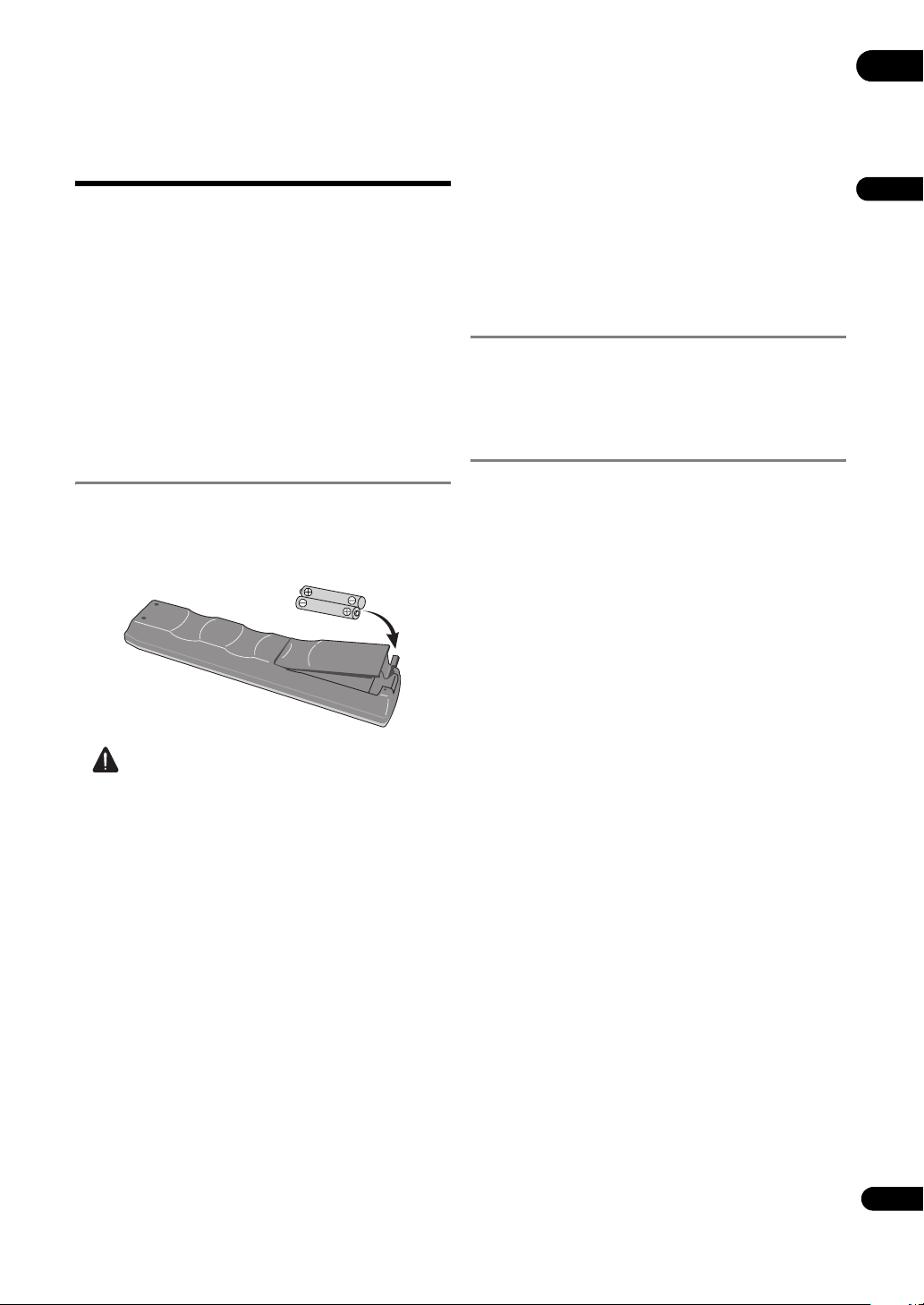
Putting the batteries in the remote control
1 Open the rear cover and insert the included
batteries (AA/R6 x 2).
Insert as indicated by the and marks in the battery
compartment.
• When disposing of used batteries, please comply with
governmental regulations or environmental public
institution’s rules that apply in your country/area.
• Do not use or store batteries in direct sunlight or
other excessively hot place, such as inside a car or
near a heater. This can cause batteries to leak,
overheat, explode or catch fire. It can also reduce the
life or performance of batteries.
Updating the firmware
When the software is updated, information concerning
this product may be published on the Pioneer website
(see below). Check the update or service information
concerning this product on the site.
Website concerning this unit
In order to allow users to take maximum advantage of this
unit’s functions, a “Communications Interface User’s
Manual” and Windows application (HD PILOT) are
available on the Pioneer website. In addition to reading
this manual, please also visit the Pioneer website.
http://www.pioneerelectronics.com/PUSA/Products/
BusinessProducts/ProfessionalVideo
(For USA and Canadian models)
http://www.pioneerprovideo.eu
(For European model)
English
Caution
• Do not use any batteries other than the ones
specified. Also, do not use a new battery together with
an old one.
• When loading the batteries into the remote control,
set them in the proper direction, as indicated by the
polarity marks ( and ).
• Do not heat batteries, disassemble them, or put them
into flames or water.
• Batteries may have different voltages, even if they look
similar. Do not use different kinds of batteries
together.
• To prevent leakage of battery fluid, remove the
batteries if you do not plan to use the remote control
for a long period of time (1 month or more). If the fluid
should leak, wipe it carefully off the inside of the case,
then insert new batteries. If a battery should leak and
the fluid should get on your skin, flush it off with large
quantities of water.
17
En
Page 18
Playable file formats
01
The file formats playable on this unit are shown below.
• Pioneer does not guarantee that all files (including those combining video and audio) created in the formats below
will operate. Check the file’s playback operation before using it.
• Check the Pioneer website for information on encoding software and settings whose operation Pioneer has
verified.
About file names
Only file names input in ASCII character code (0x20-0x7E) can be identified on this set. Other files will not operate
properly.
About the display
Up to 14 characters of file names are displayed.
• If the file name includes 15 to 120 characters, it is displayed with an abbreviated name (ex.: First 9 characters + ~
(tilde) + “.extension”)
• For file names including 121 characters or more, --- is displayed and the file cannot be played.
Note
• If the extension includes 4 or more characters, only the first 3 are displayed. (Ex.: 0123456789.mpg2
0123456789.mpg)
• Do not use the characters listed below in file names. Files including these characters may not operate or display
properly.
$, “, `, @, ~ (tilde), [ or ]
About extensions
Use the extensions below, according to the purpose.
Purpose Usable extensions
Video files
Time map table files
Bitmap files for Image Overlay “.bmp”
Text files for Text Crawl “.txt”
System files “.sch”, “.plt”, “.ust”, “.err” and “.lst” (one part of a divided file)
1. Files with other extensions cannot be played. (They are only displayed on the Navigator screen.)
2. A double extension with “.map” assigned to the video file name.
1
2
“.mpg”, “.m2t”, “.mpeg”, “.ts”
“.map”
18
En
Page 19
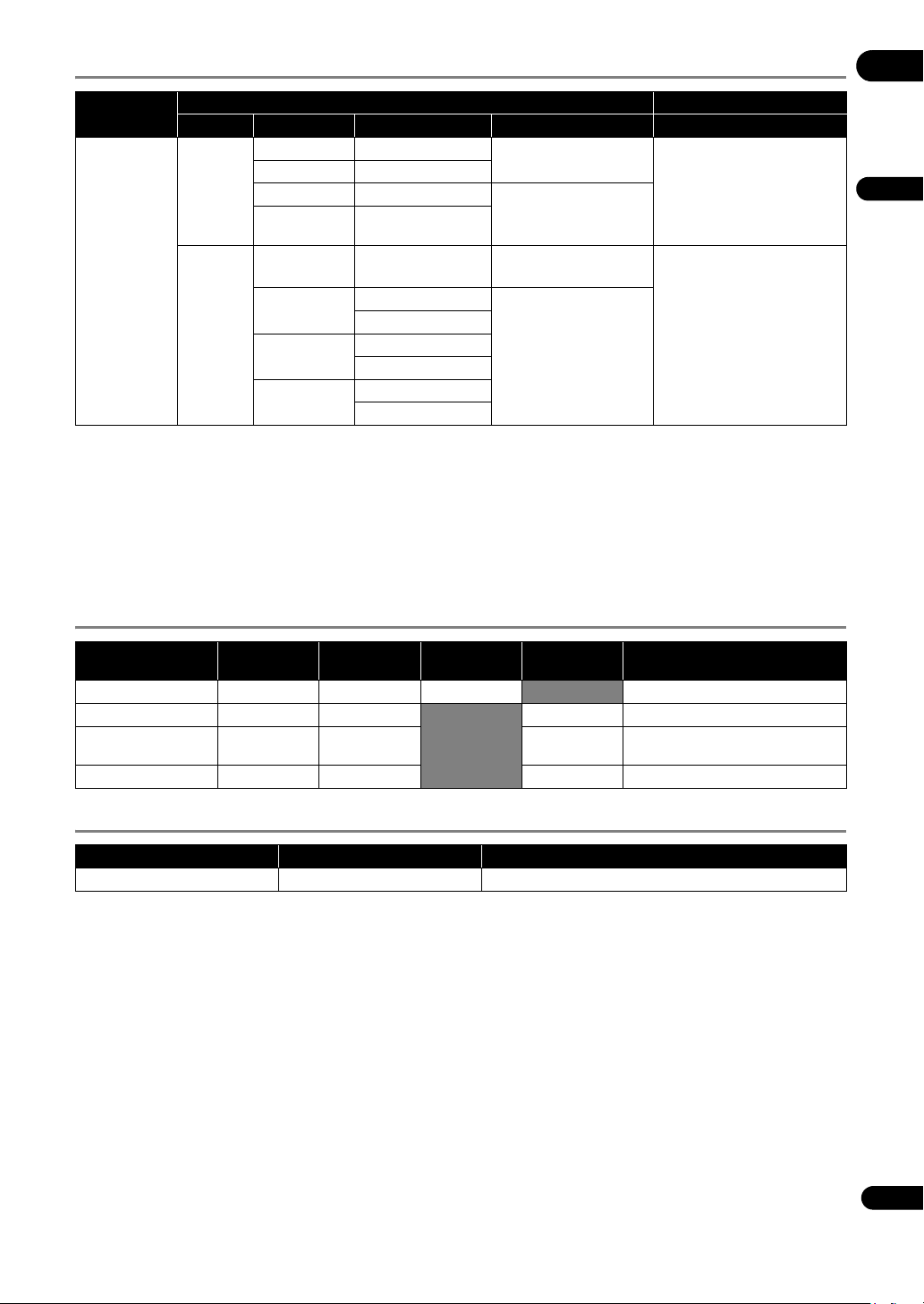
Video formats
01
Container
MPEG-2 TS
Codec Profile@Level Bit rate (max) Format Codec
MP@ML 15 Mbps
MPEG-2
(ISO/IEC
13818-2)
H.264/AVC
(ISO/IEC
14496-10)
422@ML 50 Mbps
MP@HL 60 Mbps 1280 x 720/50p, 59.94p
422p@HL 60 Mbps
MP@L3.1 14 Mbps
MP@L4.1
HP@L4.1
H422@L4
Video Audio
720 x 480/59.94i
720 x 576/50i
MPEG-1 Audio Layer-2 (MP2)
1440 x 1080/50i, 59.94i
1920 x 1080/50i, 59.94i
720 x 480/59.94i
720 x 576/50i
50 Mbps (CAVLC)
30 Mbps (CABAC)
50 Mbps (CAVLC)
30 Mbps (CABAC)
50 Mbps (CAVLC)
20 Mbps (CABAC)
1280 x 720/50p, 59.94p
1440 x 1080/50i, 59.94i
1920 x 1080/50i, 59.94i
MPEG-1 Audio Layer-2 (MP2)
AAC (MPEG-4 AAC LC)
LPCM
Dolby Digital
LPCM
Dolby Digital
• Manufactured under license from Dolby Laboratories. “Dolby” and the double-D symbol are trademarks of Dolby
Laboratories.
• When menu operations, network connections or other such operations are performed while playing video files with
a high bit rate, the picture or sound may sometimes stop or be disturbed. Furthermore, regardless of the video file’s
bit rate, the picture or sound may stop or be disturbed if SD memory card operations (copying, deleting, etc.) are
performed during playback.
• When video contents of different formats are used together, it may happen that the beginning of the contents
cannot be played.
Audio formats
English
Codec No. channels
LPCM 2CH 48 kHz 16 bits Conforming to SMPTE 302M-2002
MPEG-1 Audio Layer-2 2CH 48 kHz 384 kbps ISO/IEC 11172-3
Dolby Digital 2CH 48 kHz 448 kbps
AAC (MPEG-4 AAC LC) 2CH 48 kHz 288 kbps ISO/IEC 14496-3
Sampling
frequency
Quantization
bit no.
Bit rate (max.) Remarks
Dolby Digital Decoder
Implementation kit Version 3.0
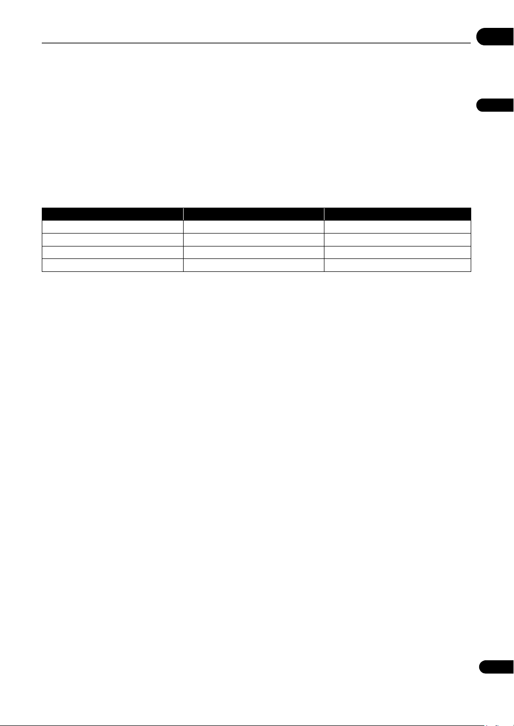
Image formats
Format Compression format Resolution
Windows bitmap Non-compressed 640 x 360 (fixed)
19
En
Page 20
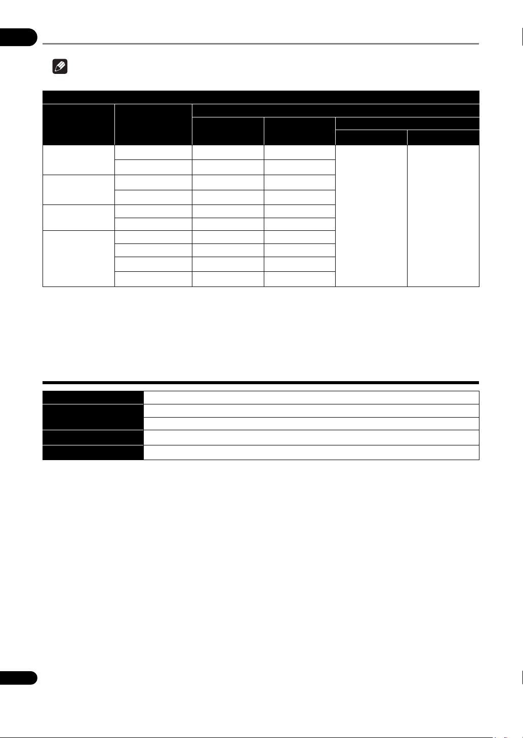
Video output formats
01
Note
• Settings in bold indicate the factory defaults.
Scaler Setting settings
Output Terminal
Resolution
720 x 480
720 x 576
1280 x 720
1920 x 1080
1. Only the resolution can be set at Scaler Setting (page 46). The frame rate is determined by the playback format.
2. TV SYSTEM switch setting (page 26)
3. When different from the video content’s frame rate, the video signals are not properly output.
4. The noise reduction function cannot be used with 1080p outputs (page 45).
Frame rate
1
3
59.94i
3
59.94p
3
50i
3
50p
59.94p
50p
59.94i
50i
4
59.94p
4
50p
COMPONENT
VIDEO OUT
HDMI OUT
• When using the external sync function, set the external synchronizing signal, playback file and Scaler Setting
(page 46) settings to the same resolution.
VIDEO OUT
2
NTSC
720 x 480/59.94i 720 x 576/50i
PAL
2
About SD memory cards
SD specifications Conforming to SD Specifications Part 2 File System Specification Version 2.00
Supported cards
File formats
Speed class
1. CPRM is not supported. Operation, transfer speed and reliability are not guaranteed on this unit.
2. • Video files on SD memory cards formatted in NTFS can be played, but their reading time will be slow, and for this reason the transfer rate
is not guaranteed.
• Formatting in NTFS is not possible on this unit.
• The NTFS format is not a format recommended by SD standards for SD memory cards. Note that for some SD memory cards, formatting
the card in NTFS may compromise reliability.
1
1
1
• SDHC memory cards can be used with devices supporting SDHC memory cards. They cannot be used with devices
that only support SD memory cards. Also, Pioneer does not guarantee that all SD memory cards will operate on
this unit.
• When using SD memory cards of 4 GB or greater, use SD memory cards on which the SDHC logo is indicated.
• SD memory cards are shipped from the manufacturer in the standard FAT16 or FAT32 format. If a non-formatted
SD memory card is loaded, SD CARD FORMAT ERROR is displayed and the card cannot be used.
• It may not be possible to use cards formatted on a computer, digital camera, etc.
• It is also possible to format SD memory cards on this unit (page 51).
• On SD memory cards formatted in FAT32, the maximum size per file is 4 GB. To play a file larger than 4 GB, divide
the file using the application (HD PILOT).
• SDHC Logo is a trademark of SD-3C, LLC.
SD memory cards: 8 MB/16 MB/64 MB/128 MB/256 MB/512 MB/1 GB/2 GB
SDHC memory cards: 4 GB/8 GB/16 GB/32 GB
FAT16/FAT32, NTFS
Class 2/4/6/10 for SDHC
2
20
En
Page 21
Cautions on using SD memory cards
• SD memory cards are precision electronic devices. Handle them with care. Bending, dropping or subjecting SD
memory cards to strong forces or shocks could damage them. Also, do not use or store SD memory cards in
environments where static electricity or electric noise tends to be produced. We recommend periodically making
copies of valuable data.
• Please note that Pioneer will accept no responsibility whatsoever for loss of data recorded by the customer on SD
memory cards or other direct or indirect problems resulting from connection to this unit.
• After ejecting SD memory cards, store them in their dedicated case, etc.
• SD memory cards may not always provide the expected performance.
• If a file name has more than 15 characters, the file name displayed on this unit is abbreviated.
• The speed of transfer from the SD memory card can be measured on this unit (page 44).
• The speed class indicates the minimum guaranteed transfer speed as defined by SD specifications. The table
below shows the transfer speed guaranteed by SD specifications and the approximate playback bit rate on this unit
for the different speed classes. These values do not indicate guaranteed operation on this unit. Be sure to check
the SD memory card’s playback operation before using it.
Speed class Guaranteed transfer speed Approx. playback bit rate
CLASS 2 2 MB/s (16 Mbps) 10 Mbps or less
CLASS 4 4 MB/s (32 Mbps) 25 Mbps or less
CLASS 6 6 MB/s (48 Mbps) 40 Mbps or less
CLASS 10 10 MB/s (80 Mbps) 60 Mbps or less
01
English
21
En
Page 22
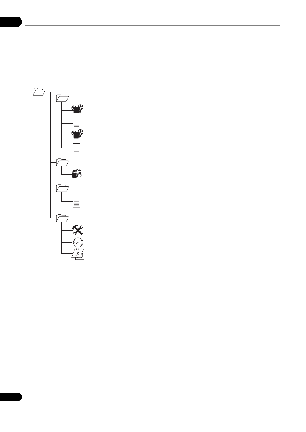
SD memory card folder structure
01
The folders video, picture, text and system are created in the root directory. The files stored in the different folders
are as shown below. Only store the specified files in the different folders. Storing a file in the wrong folder may lead to
malfunction.
• video: Video files (.mpg, .m2t, .mpeg and .ts), time map table file (.map) and one part of a divided file (.lst)
• picture: Still picture files (.bmp)
• text: Text crawl file (.txt)
• system: Settings file (.ust), playlist settings file (.plt) and schedule settings file (.sch)
Root directory
video*
001OPEN.mpg Video file
00:00
001OPEN.mpg.map Time map table file
0000f
002CLOSE.mpg
00:00
002CLOSE.mpg.map
0000f
picture*
LOGO.bmp Still picture file
text*
(one such file with the same name as the video file is created)
ABC
add.txt Text crawl file
system*
20100101000000.ust Settings file
summer.sch Schedule settings file
display.plt Playlist settings file
* For the NTFS format, only use small letters for the directory name.
22
En
Page 23

About USB storage devices
The USB storage devices that can be connected to this unit are as shown below.
• USB memory devices and HDDs (hard disk drives) supporting USB 2.0
• File system: FAT16, FAT32 or NTFS
01
Note
• This unit’s settings, playlists and schedules can be saved on and loaded from USB storage devices and the error
history saved on USB storage devices. Video files, still picture files and text crawl data stored on USB storage
devices can be played if they are copied on SD memory cards (page 51).
• USB storage devices formatted in file systems other than the ones above cannot be used.
• If multiple partitions are set on the USB storage device, the device may not be recognized.
• Some USB storage devices may not operate properly.
• Operation of connected USB storage devices (USB memories, external HDDs, etc.) is not guaranteed.
Furthermore, this unit does not support low speed devices.
Cautions on using USB storage devices
• Please note that Pioneer will accept no responsibility whatsoever for damage to USB storage devices
caused by connection of this unit, loss of data recorded on USB storage devices or loss of this unit’s setting
data, etc.
• Only files in the root directory can be loaded. Also, files saved on USB storage devices with this unit are placed in
the root directory.
• If a file name has more than 15 characters, the file name displayed on this unit is abbreviated.
• It is not possible to use two or more USB storage devices simultaneously.
• Be sure to delete any unnecessary files that are unrelated to this unit from USB storage devices before using them.
Pioneer will accept no responsibility whatsoever for loss of or damage to files on USB storage devices. Files cannot
be deleted on this unit. Delete the files using a computer.
• Do not disconnect the USB storage device while files are being read or saved.
• If an error occurs while files are being read or saved, disconnect then reconnect the USB storage device and try
again. If the error occurs again, format the USB storage device in FAT format on a computer.
• When saving, if a file with the same name already exists, the old file is overwritten.
English
23
En
Page 24
Part Names and
01
Functions
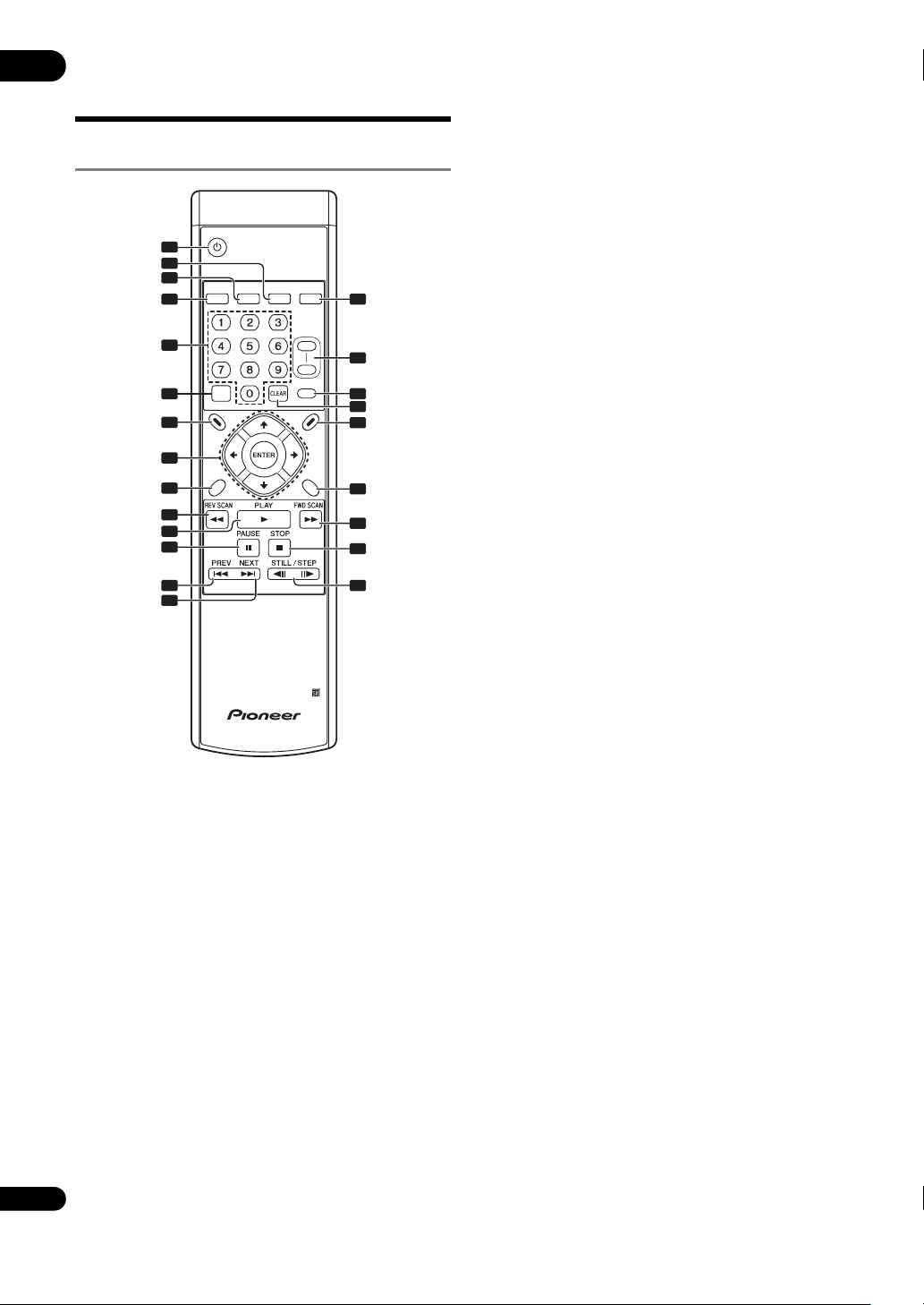
Remote Control
STANDBY/ON
1
2
3
SEARCH
4
5
FRM
6
/TIME
7
NAVI-
GATOR
8
SETUP RETURN
9
10
11
12
13
14
REPEAT MEMORY RECALL
OUTPUT
RESOLUTION
+
-
DISPLAY
PLAY
MODE
15
16
17
18
19
20
21
22
23
1 STANDBY/ON (page 37)
Press to turn the power on and off (to the standby mode).
2MEMORY (page 55)
The playlist Create/Edit screen is displayed.
3 REPEAT (page 41)
4SEARCH (page 42)
5 Number buttons
Use these to input numbers at setting menus, etc.
6FRM/TIME (page 42)
7 NAVIGATOR (page 39)
8 /// – Use these to select items, change
settings, etc. Also use them to move the cursor.
ENTER – Press this to execute the selected item or
enter a setting that has been changed, etc.
9SETUP (page 38)
10 REV SCAN (page 40)
11 PLAY (page 39)
12 PAUSE (page 39)
13 PREV (page 40)
14 NEXT (page 40)
15 RECALL (page 61)
16 OUTPUT RESOLUTION (+, –) (page 43)
17 DISPLAY (page 36)
18 CLEAR
Press to clear if you have input the wrong number.
19 PLAY MODE (page 42)
20 RETURN
Press to return to the previous screen.
21 FWD SCAN (page 40)
22 STOP (page 39)
23 STILL/STEP (page 41)
24
En
Page 25
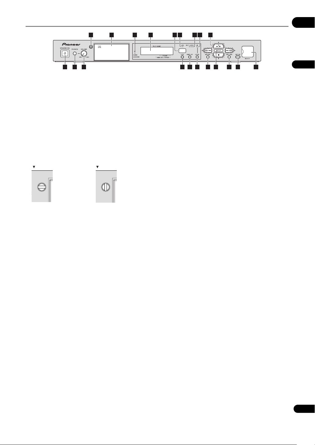
Front Panel
01
4 125 6 7 8 10 119
1 3 13 1714 15
2
1 STANDBY/ON
Press to turn the power on and off (to the standby mode).
The indicator lights green when the power is on, orange
when the power is off (in the standby mode).
2PHONES
Connect headphones here.
3 VOLUME (MAX, MIN)
Adjusts the volume of the sound output from the
headphones.
4Door lock key
Locks the SD memory card insertion slot.
Locked Unlocked
Groove is
horizontal
Groove is
vertical
5 SD memory card insertion slot (page 37)
Press PUSH OPEN to open the door, then insert the SD
memory card. To close (or lock) the door, check that the
door lock key is unlocked.
Never eject the SD memory card or unplug the power
cord while the ACCESS indicator is flashing. Doing so
may destroy the data.
6 CARD ACCESS indicator
This flashes when the SD memory card is being read or
written.
7 Main unit display
The main unit display’s backlight turns off automatically
if no operation is performed for three minutes, then lights
when an operation is performed.
16
18
19
20
8 Remote control sensor
Point the remote control towards this sensor and operate
it within a range of about seven meters (23 ft.).
The unit may have trouble capturing remote control
signals if there is a fluorescent light nearby. If this
happens, move the unit away from the fluorescent light.
9LAN indicator
This flashes when signals are being exchanged with a
device connected to the LAN port.
10 KEY LOCK indicator
This lights when the front panel’s buttons are locked. The
indicator flashes if main unit buttons are operated while
they are locked.
11 IR LOCK indicator
This lights when remote control buttons are locked. The
indicator flashes if remote control buttons are operated
while they are locked.
12 – Press to start playback. When pressed during
playback, the pause mode is set. When the SETUP
indicator is lit, operates as the button, moving the
cursor upward.
/ – Press to skip to the beginning of the
previous file. Press and hold to start reverse scanning
(page 40). When the SETUP indicator is lit, operates
as the button, moving the cursor to the left.
/ – Press to skip to the beginning of the next
file. Press and hold to start forward scanning
(page 40). When the SETUP indicator is lit, operates
as the button, moving the cursor to the right.
– Press to stop playback. When the SETUP
indicator is lit, operates as the button, moving the
cursor downward.
English
25
En
Page 26
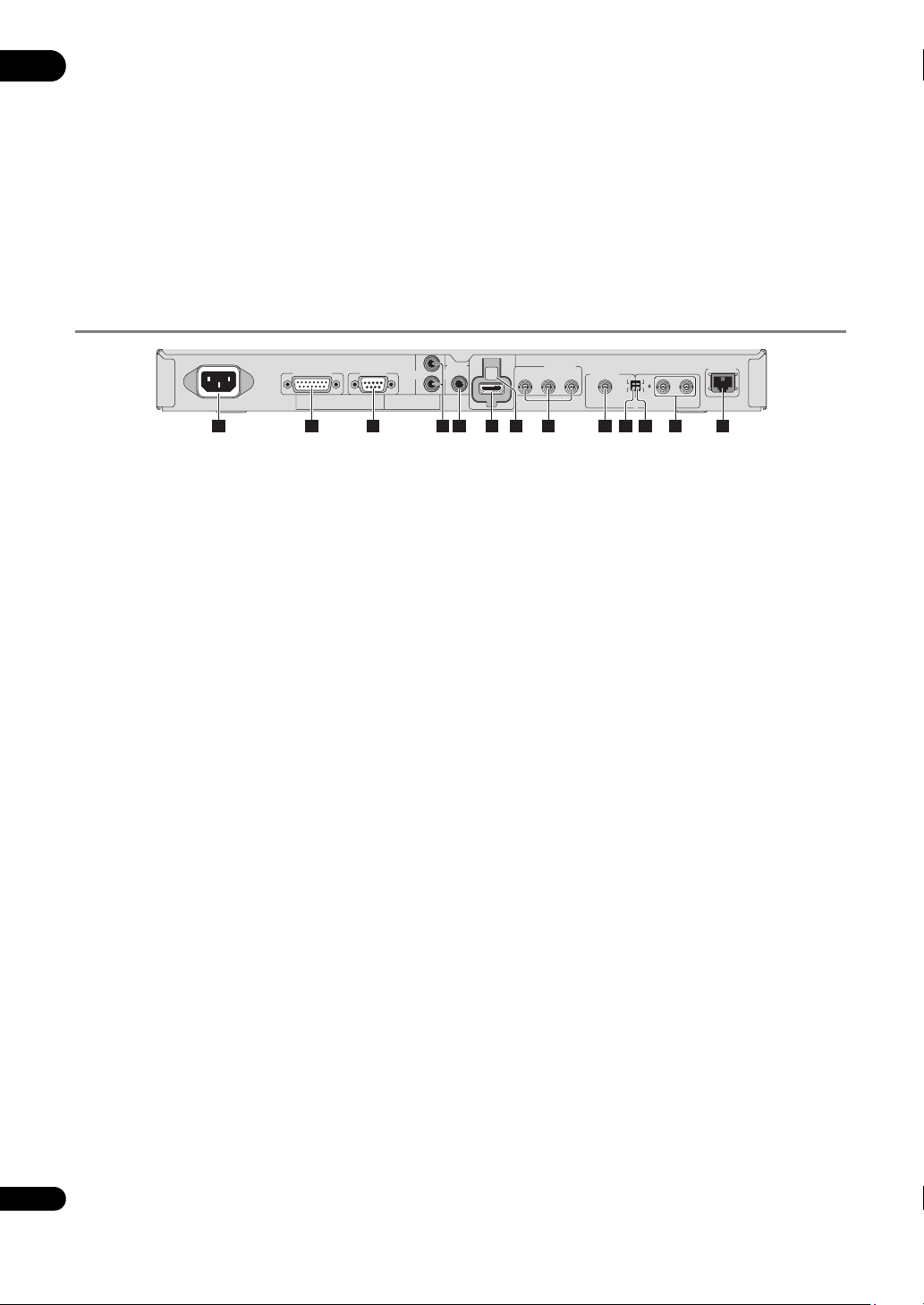
13 LCD (page 35)
01
Press to switch the liquid crystal display. When pressed
while the main unit display’s backlight is off, the backlight
turns on. (When pressed after the backlight has turned
on, switches the display.)
14 DISPLAY (page 36)
15 LOCK
Press to lock the remote control buttons. When pressed
again, the buttons are unlocked.
Rear Panel
16 ENTER
Use this to execute the selected item, enter settings that
have been changed, etc.
17 SETUP indicator (page 38)
This lights when this unit is in the SETUP mode.
18 RETURN
Press to return to the previous screen.
19 SETUP (page 38)
Press to display the SETUP screen.
20 USB ports (MEMORY) (page 34)
USB storage devices can be connected here.
AC IN
RS-232CEXT TERMINAL
L
AUDIO
OUT
R
1 2 3 9 12 135 64 10 118
1AC IN (page 34)
2 EXT TERMINAL (page 67)
An external switch can be connected here to operate this
unit. This can also be used as an RS-232C interface.
3 RS-232C (page 64)
A computer can be connected here for serial control of
this unit.
4 AUDIO OUT (L, R) (page 32)
5 DIGITAL AUDIO OUT (page 33)
6 HDMI OUT (page 31)
7 HDMI holder (page 31)
Use this to fasten the HDMI cable in place when
attaching the included HDMI retaining cover.
8 COMPONENT VIDEO OUT (Y, CB/PB, CR/PR)
(page 32)
HDMI
DIGITAL
AUDIO
OUT
COMPONENT
OUT
VIDEO OUT
VIDEO OUT
C
R
/ PRCB / PBY
SYSTEM
ON
NTSC
TV
75
OFF
PAL
EXT SYNC IN
LAN(10/100)
7
9VIDEO OUT (page 32)
10 TV SYSTEM (NTSC, PAL) (page 33)
Switches the TV system for the VIDEO OUT terminal
(composite output). This also switches the refresh rate
when HDMI and component output starts (NTSC: 59.94
Hz, PAL: 50 Hz). Upon purchase, the switch is set to NTSC
(USA and Canadian models)/PAL (European model).
11 75 Ω (ON, OFF) (page 48)
This switch is for terminating the external synchronizing
signal. Upon purchase, the switch is set to ON.
12 EXT SYNC IN (page 48)
This is the external synchronizing signal input/output
terminal.
13 LAN (10/100) (page 33)
LINK indicator (yellow): This lights when the link is
established with the device connected to the LAN
terminal.
LAN indicator (green): This flashes when signals are
being exchanged with the device connected to the LAN
terminal.
26
En
Page 27

Chapter 2
Installation
02
Cautions on use
• Please note that Pioneer will accept no responsibility
whatsoever for loss of business opportunities or other
damages due to breakdown of this unit or other such
causes.
• Please note that Pioneer will accept no responsibility
whatsoever for problems resulting from the use of
this unit, regardless of the method of installation.
• Please note that Pioneer will accept no responsibility
whatsoever for loss of data resulting from use or
breakdown of this unit, or for any direct or indirect
damages incurred thereby.
Cautions on Installation
Place of installation
• Select a stable, flat place to install this unit. Do not
place it in an unsteady, unstable place or a place
exposed to heavy vibrations.
• Avoid the following types of places:
– On top of TVs or color monitors
– Near cassette decks or other components easily
affected by magnetism.
– Places exposed to direct sunlight or strong artificial
light
– Places subject to vibration
– Places exposed to strong electromagnetic or
magnetic forces
– Places in which there is much electrical noise
– Places in which electrostatic noise tends to be
generated
– Humid or poorly ventilated places
–Closed racks
– Extremely hot or cold places
– Places in which there is much dust or cigarette
smoke
– Places exposed to soot, steam or heat (in kitchens,
etc.)
Surrounding temperature and
humidity during use
This unit should be used within a surrounding
temperature range of 0 °C to 45 °C and a relative humidity
of 85 % or less. When stacking units of this unit (up to
three units), the upper limit for the surrounding
temperature should be about 35 °C. Furthermore, when
mounting on a rack or in any other closed place, or when
installing near devices that generate heat, the
temperature around this unit should be 45 °C maximum.
• The unit may be set to the standby mode or playback
may stop if the internal temperature rises. If this
happens, change the place of installation, usage
conditions, etc.
Do not place objects on top
Do not place other products, display devices, etc., on top
of this unit.
Do not obstruct the ventilation
holes
Do not use this unit on a shaggy rug, bed, or sofa, and do
not cover this unit with a cloth, etc. Doing so will prevent
heat dissipation and could lead to damage.
Keep away from heat
Heat may lead to unstable operation or fire.
• When installing this unit, make sure to leave space
around the unit for ventilation to improve heat
radiation (at least 5 cm at top, 5 cm at rear, and 5 cm
at each side).
• Install the seat away from other devices.
When installing multiple units
• Up to three units of this unit can be stacked.
• The current will surge if the power to several units of
this unit is turned on or off (to the standby mode)
simultaneously from an external device. For the value
per unit, see page 81.
English
27
En
Page 28

When mounting on a rack
02
Be sure to use the included rack mount brackets. Using
anything else could damage this unit or result in injury.
For details on mounting, see below.
• This unit has a rack mount size of 1U.
• The included rack mount brackets can be used to
mount this unit onto an EIA 19-inch universal pitch or
wide pitch rack.
Cautions on moving this unit
Moving this unit with an SD memory card inside could
damage it. Stop data access to the SD memory card then
eject the SD memory card before moving this unit. Also,
press the STANDBY/ON button, check that the
indicator switches from green to orange, then unplug the
power cord. Unplugging the power cord before the
indicator switches to orange could destroy the data on
the S D memo ry card o r restor e this un it’s set tings to their
factory defaults.
•The STANDBY/ON indicator may remain lit for
several dozen seconds after the power cord is
unplugged. This is not a malfunction. Make sure the
STANDBY/ON indicator has turned off before
moving this unit.
Transporting this unit
When transporting this unit, be sure not to subject it to
vibrations or shocks or to drop it. Do not let this unit be
exposed to heat or water during transportation.
Be sure to remove any SD memory card before
transporting this unit. Transporting this unit with an SD
memory card in it could cause internal damage to this
unit. Also, disconnect cables. Transporting with cables
connected could damage the terminals.
Condensation
If this unit is moved suddenly from a cold place into a
warm room (in winter, for example) or if the temperature
in the room in which this unit is installed rises suddenly
due to a heater, etc., water droplets (condensation) may
form inside. When condensation is present, this unit will
not operate properly and playback is not possible. Let this
unit stand at room temperature for one or two hours with
the power turned on (the time depends on the extent of
condensation). When this unit is kept at room
temperature, the water droplets will dissipate and
playback will become possible.
Condensation can also occur in the summer if this unit is
exposed to the direct wind from an air-conditioner. If this
happens, move this unit to a different place.
Cleaning this unit
Normally, wipe this unit clean with a soft cloth. For tough
dirt, apply some neutral detergent diluted in five to six
parts water to a soft cloth, wring out thoroughly, wipe off
the dirt, then wipe again with a dry cloth.
Note that getting alcohol, thinner, benzene or insecticide
on this unit could cause the print and coating to peel off.
Also, avoid leaving rubber or vinyl products in contact
with this unit for long periods of time, as this could
damage the cabinet.
When using chemical-impregnated wipes, etc., read the
wipe’s cautions carefully.
Unplug the power cord from the power outlet when
cleaning this unit.
Mounting on a rack
Caution
• The rack mount brackets included with this unit allow
this unit to be mounted on universal pitch or wide
pitch racks conforming to EIA 19-inch standards.
• The included rack mount brackets are exclusively for
use with this unit. Never mount them on other devices
or use them for other purposes; doing so is
dangerous. Note that Pioneer will accept no
responsibility whatsoever for any damages due to use
of the rack mount brackets for other purposes, nor for
any loss of business opportunities or other damages
due to installation of this unit.
• Check that the rack has the appropriate strength for
this unit’s weight and usage environment before
mounting.
• The screws for fixing the rack mount brackets to the
rack (indicated as * in page 29) are not included.
Choose screws with the appropriate strength and
length for this unit’s weight and usage environment
to mount this unit on the rack. To ensure that this unit
is fixed securely on the rack, be sure to fasten it with
screws in all four rack mount screw holes.
• For the positions of the rack mount brackets’
mounting screw holes, see page 30.
• The mounting procedure should be performed by at
least two people.
• When mounting, be extremely careful not to get your
fingers, etc., caught between the rack mount
brackets and the rack.
1 Disconnect all cords connected to this unit
(including the power cord).
Before starting, make sure there is no SD memory card in
this unit.
2 Mount the rack mount brackets.
Caution
• Be sure to use the included screws when mounting
the rack mount brackets. Using any other screws
could damage this unit or cause it to fall.
28
En
Page 29
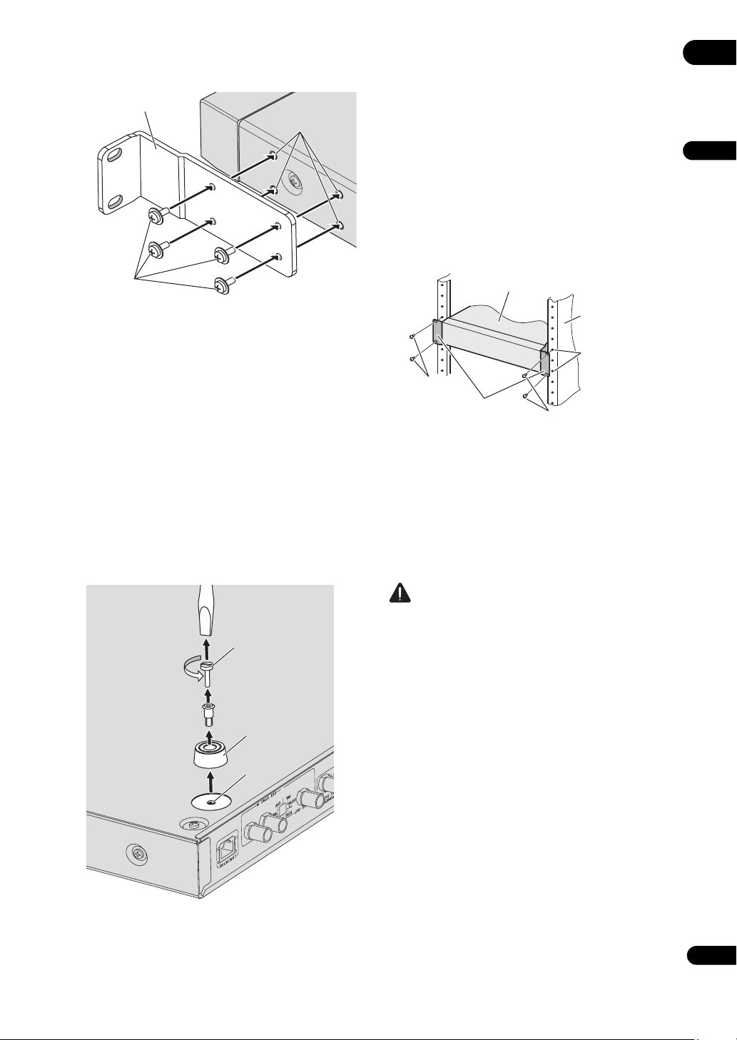
Attach the included rack mount brackets to the screw
holes in the side of this unit using the included screws,
four screws per side.
Rack mount bracket
Screw holes in side
• The feet will be needed again if this unit is installed
without using a rack, so be sure to store them in a
safe place.
• To reinstall the feet on this unit, insert the foot into the
foot fixing hole in this unit, then press the plastic
screw section in.
• Do not mount anything other than the feet that were
removed (including the plastic screw section).
Mounting other feet may damage this unit. If you lose
the feet, contact the after-sales service center
(indicated on the rear panel).
4 Mount this unit on the rack.
Check that the screws fastened in step 2 are securely
tightened.
02
English
Included
screws
• When attaching, first tighten the four included
screws temporarily so that the rack mount bracket
still moves when a light force is applied, check that
the rack mount bracket is properly attached, then
tighten the screws to fasten the rack mount bracket
securely.
• If the rack space in which this unit is to be installed is
only 1U size, proceed to step 3.
• If the rack space in which this unit is to be installed is
greater than 1U size and there is space of more than
10 mm under this unit, proceed to step 4.
3 Turn this unit upside-down and remove the four
feet.
Use a flat-blade screwdriver to turn the “–” part of the
plastic screw section on the foot counterclockwise,
loosen until the plastic screw section’s head comes out of
the foot, then remove the foot from this unit.
Plastic screw
Remove foot
Foot fixing
hole
This unit
Rack
(Conforming to EIA
standards)
Rack mount
mounting screw
Screws (*)
Rack mount
brackets
holes
Screws (*)
5 Check that the screws fastened in step 4 are
securely tightened.
Once this is checked, mounting is completed.
• If the * screws or the rack mount bracket’s screws are
loose, vibrations generated by other products could
cause noise or to lead this unit falling off the rack,
resulting in injury or damage to the equipment. Be
sure to check that the screws are securely fastened.
Caution
• Pay attention to the following when removing this unit
from the rack and moving it:
– Be sure to remove any SD memory card from this
unit.
– Turn this unit’s power off, then disconnect
connected cables, etc.
– Be careful that this unit does not fall when
loosening the screws fastening it to the rack (the
procedure should be performed by at least two
people).
– After removing this unit from the rack, be sure to
place it on a stable surface, such as on a flat table.
• When wiring after installing this unit, fasten the
cables to the rack. If your feet get caught in the
cables, a strong force could be exerted on this unit’s
terminals, damaging this unit.
29
En
Page 30
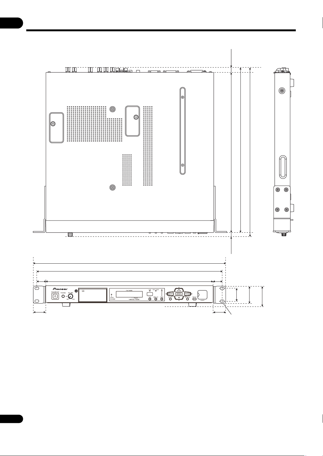
External Dimensions/Weight
02
Unit: mm
(12.1)
(Not including projecting parts)
400
412
422.3
(483)
465
22.5
31.5
420
• For improvement purposes, the above external appearance and specifications
are subject to change without prior notice.
Main unit weight: 5 kg
Rack mount bracket weight: Approx. 0.3 kg (total of left and right brackets)
30
En
22.5
31.5
(10.3)
43.7
31.7
Elongated holed
(6.4 x 10) (4 holes)
51.4
Page 31

Chapter 3
O
O
Connections
03
Be sure to turn off the power (set it to standby) then
unplug the power cord from the power outlet whenever
making or changing connections.
Also refer to the operating instructions of the device
being connected.
Connecting the HDMI OUT terminal
Using a single cable, video and audio signals can be
transmitted to HDMI-compatible equipment as digital
signals with no loss of quality.
Note
• This unit is designed for connection with HDMIcompatible devices. Do not connect DVI devices. This
unit may not operate properly if a DVI device is
connected.
• 1080p video signals may not be output, depending on
the HDMI cable being used.
About HDMI
This unit incorporates High-Definition Multimedia
Interface (HDMI
®
) technology.
Audio signals that can be
transferred with the HDMI OUT
terminal
• Linear PCM (The following linear PCM signals can be
output):
– Sampling frequency: 48 kHz
– No. channels: 2
Attaching the HDMI retaining cover
This unit comes with an HDMI retaining cover for
preventing the HDMI cable from coming loose. Be sure to
attach the cover.
Note
• Depending on type of HDMI cable connected, it may
not be possible to fasten the cable with the HDMI
retaining cover. In this case, fasten in place using the
four fixing holes used when using a binder in step 1
below.
• The connector sizes of HDMI cables which can be
fastened with the HDMI retaining cover are shown
below. However, depending on the shape of the
connector, the position of the cable, etc., it may not be
possible to fasten the cable.
Cable
Ø12 mm or less
18 mm to 21 mm
10 mm to 12 mm
English
• HDMI, the HDMI Logo and High-Definition
Multimedia Interface are trademarks or registered
trademarks of HDMI Licensing, LLC in the United
States and other countries.
Note
• This unit does not support HDCP. HDCP is a standard
for protecting audio and video contents with HDMI or
DVI connections. Copyright-protected contents
cannot be played on this unit.
• This unit does not support Deep Color, xvYCC or CEC.
• For the video output resolutions, see Video output
formats on page 20.
22 mm to 26 mm
Connector sizes of HDMI cables which can be fastened
with the HDMI retaining cover (reference values)
1 Attach the HDMI cable to this unit’s HDMI OUT
terminal.
RS-232C
HDMI retaining cover
Screw
3
AUDIO
L
OUT
R
HDMI screw hole
DIGITAL
AUDIO
OUT
HDMI
OUT
1
2
HDMI cable
HDMI holder
Fixing holes for
binding (4 holes)
COMPONENT
Y
VIDEO OUT
C
B
/ P
B
C
R
/ P
R
VIDEO OUT
NTSC
TV
SYSTEM
PAL
31
En
Page 32

2 Attach the HDMI retaining cover to the HDMI
03
cable.
Mount the HDMI retaining cover so that it retains the
connector securely.
• Depending on the HDMI cable’s connector size, the
gap and positional relationship between the HDMI
retaining cover and HDMI holder may differ.
3 Tighten the HDMI retaining cover’s screw into
the HDMI screw hole to fasten the HDMI cable to this
unit.
Caution
• Do not tighten the screw with excessive force. Doing
so could damage the connector or cable.
•If the HDMI retaining cover is damaged, do not
continue using it. The cable could come loose or the
terminal could be damaged.
• The HDMI retaining cover is only designed to retain
the connector. This does not provide strength against
loads applied when the cable is pulled on, so be sure
to fasten the cable to the rack, etc.
Connecting to a display
When also connecting to an amplifier using the HDMI
cable, see Connecting to an amplifier (below).
Connecting to an amplifier
For instructions on connecting the amplifier and display
or the amplifier and speakers, see the amplifier’s
operating instructions.
Caution
• Hold the connector when connecting and
disconnecting cables.
• Applying excessive force to the connector could
result in faulty contact and prevent video signals from
being output.
Rear panel
L
AUDIO
OUT
R
HDMI cable
(commercially
available)
From HDMI
output
terminal
DIGITAL
AUDIO
OUT
HDMI cable
(commercially
available)
HDMI
OUT
To HDMI
input
terminal
COMPONENT
VIDEO OUT
C
VIDEO OUT
R / PRCB / PBY
Amplifier
LAN(10/100)
ON
NTSC
TV
75
SYSTEM
OFF
PAL
EXT SYNC IN
Direction of signal flow
To HDMI input
terminal
Display
Match the direction
of the plug to the
terminal and insert
the plug straight in.
Caution
• Hold the connector when connecting and
disconnecting cables.
• Applying excessive force to the connector could
result in faulty contact and prevent video signals from
being output.
Rear panel
L
AUDIO
OUT
R
HDMI cable
(commercially
available)
HDMI
DIGITAL
AUDIO
OUT
COMPONENT
OUT
VIDEO OUT
To HDMI
input
ON
75
OFF
EXT SYNC IN
LAN(10/100)
Match the direction
of the plug to the
terminal and insert
the plug straight in.
VIDEO OUT
C
R / PRCB / PBY
NTSC
TV
SYSTEM
PAL
It is also possible to connect this
unit to an amplifier using the
HDMI cable. (See below)
Display
Direction of
signal flow
Connecting the VIDEO OUT and AUDIO OUT terminals
Connecting to a display
Rear panel
L
AUDI O
S-232C
OUT
R
It is also possible to connect
to an amplifier. Use an audio
cable (2-channel) or coaxial
Audio cable
(commercially available)
digital audio cable to
connect (see page 33).
To audio input terminal
Display
Direction of signal flow
HDMI
DIGITAL
AUDI O
OUT
COMPONENT
OUT
VIDEO OUT
To video input terminal
To component
video input
terminals
Connect the VIDEO
OUT terminal or
COMPONENT VIDEO
OUT terminals. Use a
BNC cable with a
characteristic
impedance of 75 Ω.
VIDEO OUT
R / PRCB / PBY
C
ON
NTSC
TV
75
SYSTEM
PAL
OFF
(commercially
available)
EXT SYNC IN
BNC cable
32
En
Page 33

Note
S
• Only video signals with NTSC or PAL resolutions are
output from the VIDEO OUT terminal. Set the output
using the TV SYSTEM (NTSC, PAL) switch on this
unit’s rear panel (page 26).
• Video signals with the resolution set at Setup are
output from the COMPONENT VIDEO OUT terminals
(set to 480/59.94i (USA and Canadian models)/576/50i
(European model) upon shipment from factory). It is
not possible to output signals with a resolution
differing from the HDMI output (page 46).
•When EDID is set to On and HDMI connections are
used, the HDMI output’s resolution setting has
priority, so the output resolution of the signals output
from the COMPONENT VIDEO OUT terminals may
change automatically (page 46).
• When there is a display for monitoring, we
recommend connecting it to the VIDEO OUT
terminal.
Connecting the DIGITAL AUDIO OUT terminal
Rear panel
L
AUDI O
S-232C
OUT
R
2-channel
analog audio
signals can
also be
Video/audio cable
(commercially available)
connected.
To audio input
terminals
Note
• The following linear PCM signals can be output from
this unit’s DIGITAL AUDIO OUT terminal:
– Sampling frequency: 48 kHz
– No. channels: 2
• To switch the picture with the amplifier, also connect
the VIDEO OUT terminal.
HDMI
DIGITAL
OUT
AUDI O
OUT
Coaxial digital
audio cable
(commercially
available)
To coaxial digital
audio input terminal
Amplifier
COMPONENT
VIDEO OUT
C
R / PRCB / PBY
Direction of
signal flow
VIDEO OUT
SYSTEM
ON
NTSC
TV
75
OFF
PAL
EXT
Connecting the LAN (10/100) port
Use this to connect this unit to a hub connected to a
network, etc. For details on this unit’s network functions,
see page 70.
Be sure to connect to an Ethernet hub or router
compatible with 100BASE-TX.
Connecting to an Ethernet hub
This unit can be connected to an Ethernet hub using a
LAN cable.
Caution
• Use an STP cable for the LAN cable. Failure to do so
could result in serious electromagnetic problems.
Rear panel
VIDEO OU
T
ON
NTSC
TV
75
SYSTEM
OFF
PAL
EXT SYNC IN
LAN
Ethernet hub
(router with hub
functionality)
Note
• The LAN indicator on front panel lights when
connected to the network (page 25).
•If DHCP is set to TYPE in the network settings and
there is an available DHCP server on the connected
network, the IP address is obtained automatically. If
no DHCP server is available, set the IP address
manually (page 49).
• Note that Pioneer will accept no responsibility
whatsoever for any communication errors or
malfunctions associated with your network
connection and/or your connected equipment.
Please contact your network device manufacturer.
LAN(10/100)
1
23
LAN cable
(commercially
available)
WAN
03
English
33
En
Page 34

Connecting USB
03
Connecting the power
storage devices
Caution
• Be sure to turn this unit’s power off (to the standby
mode) before connecting or disconnecting USB
storage devices.
• When using an external HDD (hard disk drive) as the
external storage device, be sure to turn on the HDD’s
power before turning on this unit’s power.
• If the USB storage device is write-protected, be sure
to disable the write-protection.
• When connecting the USB cable, hold onto the plug,
set the plug in the proper direction for the port, then
insert it horizontally.
• Placing excessive loads on the plug may result in
faulty contact, making it impossible to read the data
on the USB storage device.
• Do not unplug the power cord when a USB storage
device is connected and this unit’s power is turned
on.
Rear panel
cord
Connect the power cord after all the connections between
the devices have been completed.
Rear panel
Uninterruptible
power supply, etc.
AC IN
Power cable
(included)
EXT TERMINAL
USB
memory,
etc.
Note
• It is not possible to use the two USB ports
simultaneously.
• Devices may not work if connected to the USB port via
a memory card reader or USB hub.
• Use a USB cable with a length of two meters or less.
USB cable
(commercially
available)
Hard disk
drive, etc.
34
En
Page 35

Chapter 4
Display
04
Main unit display
Displaying the playing status
1 Press the LCD button on the main unit’s front
panel.
The main unit display changes as shown below each time
the LCD button is pressed.
1. Frame display (initial display) 2. Time display
3. Repeat/playlist display 4. HDMI/resolution display
5. Video output display 1. Frame display ...
1. Frame display
File name
001OPEN.mpg
0000000
Status Frame
: Play mode
: Pause mode
: Still picture play mode
2. Time display
4. HDMI/resolution display
HDMI connection
On: Enabled
Off: Disabled
HDMI :On
1920X1080/59 .94 i
HDMI video output resolution (page 20)
5. Video output display
Video Out
NTSC
Video output – TV system: NTSC/PAL
Adjusting the main unit display’s
contrast
1 Press the LCD button on the main unit’s front
panel for over one second.
The display switches as shown below, and the contrast
level changes while the button is pressed.
C
ONTRAST ADJUS
Min Ma
2 Release the LCD button when the desired
contrast level is reached.
The contrast is set.
T
x
English
001OPEN.mpg
m0 0000 s00f
SecondsMinutes Frame
3. Repeat/playlist display
Current repeat setting
Off: None
File: Current file only
All: All files
Repeat Off
Playl ist Off
Playlist display:
Off (when not using a playlist)
1 to 20 (when using a playlist)
Checking error messages
When an error occurs, a message appears, as shown
below.
Example of error message
EEPROM ERROR
35
En
Page 36

Monitor OSD
04
On Screen Display
With the Monitor OSD setting, the playback information
is superimposed over the picture of the display connected
to this unit’s VIDEO OUT terminal (page 46).
Ex.: When Monitor OSD is set to Bottom
Normal display
During playback, the information below is displayed.
File name (Characters 9 and over are abbreviated) Codec
02CLOSE.mpg MPEG20
00m18s 000m12s 000m30s0
0000311 0000769
Current time
Current frame Total frames
Total timeRemaining time
Display during frame segment play
When playing playlists with frame control, the
information below is displayed.
When On Screen Display is set to On, the playback
information is displayed on the display connected to this
unit’s COMPONENT VIDEO OUT, HDMI OUT or VIDEO
OUT terminals (page 46).
STANDBY/ON
SEARCH
REPEAT MEMORY RECALL
OUTPUT
RESOLUTION
+
+
-
-
FRM
/TIME
NAVI-
GATOR
SETUP RETURN
DISPLAY
MODE
PLAY
1 Press the DISPLAY button during playback.
The display switches as shown below. The setting
switches between displayed and not displayed each time
the button is pressed.
Display during playback
Current time
Remaining time Total frames
Current frame
Total time
**************
**m**s***m**s***m**
*
ake r=Fr ame 0005800M
***m**
Remaining time to marker
address frame
stoMarker
Marker address
frame
Note
•When Monitor OSD is set to On, error messages are
also displayed.
36
En
status
rate
Playback
mark
Current time
Time 999m99s 999m99s 999m99s
Frame
Playing
Play
Tr.Rate :00.0Mbps
Playing bit
s
Name of
contents
**************
Elapsed Remain Total
9999999 9999999
Current
frame
Total time
Remaining
time
000m00s00f
Repeat/
playlist type
Playlist
Total no.
frames
Page 37

Chapter 5
Basic Operation
05
Loading the SD memory card
Caution
• If the SD memory card is inserted or removed while
this unit’s power is still on, it may not play properly. If
this happens, turn the power off then back on to
reload the SD memory card’s information.
STANDBY/ON
SEARCH
REPEAT MEMORY RECALL
OUTPUT
RESOLUTION
+
-
FRM
/TIME
NAVI-
GATOR
SETUP RETURN
1 Set the groove in the door lock key on the main
unit’s front panel so that it is vertical.
The door is unlocked and can now open.
Unlocked
2 Open the door and load the SD memory card.
Hold the SD memory card with the front facing upwards
and insert it slowly all the way into the slot until it stops.
3 Close the door and set the groove in the door lock
key so that it is horizontal.
The door is locked and no longer opens.
DISPLAY
PLAY
MODE
Groove is
vertical
Locked
Groove is
horizontal
4 Turn on the power.
Press the STANDBY/ON button.
Playback is possible once the POWER ON message
appears. About one minute is required before playback
becomes possible. Take this startup time into account
when controlling the power externally.
Note
• See page 22 for the folder structure of SD memory
cards used on this unit.
Removing the SD memory card from this unit
Caution
• Do not pull the SD memory card out or unplug this
unit’s power cord while the CARD ACCESS indicator
is flashing. Doing so could destroy the data recorded
on the card.
1 Turn off the power.
Press the STANDBY/ON button. After the POWER OFF
message appears, the display turns off and the
STANDBY/ON button’s indicator switches from green
to orange.
2 Set the groove in the door lock key so that it is
vertical.
The door is unlocked and can now open.
3 Open the door, push the SD memory card in so
that it pops out a little, then pull it out horizontally.
• Do not forcibly insert or pull out the SD memory card.
Doing so could damage the SD memory card or lead
to malfunction of this unit.
• Do not insert any objects other than SD memory
cards into the SD memory card insertion slot.
Inserting coins or other metal objects could damage
the internal circuitry and lead to malfunction.
• If the SD memory card is inserted or removed while
this unit’s power is still on, it may not play properly. If
this happens, turn the power off then back on to
reload the SD memory card’s information.
English
37
En
Page 38

Basic operation of the
05
settings and menu
screens
The procedure may differ according to the selected menu
and item.
STANDBY/ON
SEARCH
REPEAT MEMORY RECALL
OUTPUT
RESOLUTION
+
-
FRM
/TIME
NAVI-
GATOR
SETUP RETURN
DISPLAY
MODE
PLAY
3 Select the item you want to set.
Use the /// buttons to select, then press the
ENTER button.
Ex.: Initial Settings screen
Initial Settings
VideoOutput Scaler
Display
Options
EDID
TV Screen
Still Picture
Sync Out
External Sync
1920x1080i
Off
4:3
Frame
Off
Off
4 Change the setting.
Use the /// buttons to select, then press the
ENTER button.
720x480i 720x480p
720x576i 720x576p
1280x720p
1920x1080p
1920x1080i *
5 At the confirmation screen, select OK.
Use the /// buttons to select, then press the
ENTER button.
•If CANCEL is selected, the unit returns to the previous
step.
•If RETURN is pressed, the procedure returns to the
previous level in the menu.
1 Display the Setup screen.
Press the SETUP button. The SETUP indicator on the
main unit’s front panel lights.
ENTER
Setup
ADV.Settings Menu
File Management
Return
RETURN
Play Menu
Navigator
Play Mode
Playlist
Schedule
Load/Save
Exit
SETUP
Setting Menu
Video Settings
Audio Settings
Initial Settings
Network Settings
Information Menu
System Information
Move Select
2 Select the menu you want to set.
Use the /// buttons to select, then press the
ENTER button.
• The cursor can also be moved using the , ,
/ and / buttons on the main unit’s
front panel.
Note
• Items that cannot be changed are displayed in gray.
The items that can be selected depend on the set’s
status.
To close the settings screen
Press SETUP or RETURN.
• If the setting has been changed, be sure to either
close the Setup screen or return to the screen in
step 1. If any other operation is performed, the setting
will not be reflected.
Inputting numbers
1 Input the numbers.
Use the number buttons (0 to 9) to input the numbers.
To clear numbers you have input, press the CLEAR
button.
Ex.: Inputting the time for the Time Search function
Enter The Time
045 00
• To start playing from 45 minutes, input 4, 5, 0 and 0.
• To start playing from 1 hour, 20 minutes, input 8, 0, 0
and 0.
.
38
En
Page 39

Ex.: Inputting the IP address
IP Address
190.000.000
000
.
• Input the IP address three digits at a time. Once you
have finished inputting three digits, press the
button to move the cursor. (If a fourth digit is input,
the first number that was input is cleared.)
• Numbers between 0 and 255 can be input. If an
invalid value is input, the input cannot be entered.
2 Enter the input.
Press the ENTER button.
Inputting characters
1 Input the characters.
Use the /// buttons to select, then press the
ENTER button. To clear characters you have input, press
the CLEAR button.
Ex.: FTP user name input screen
FTP Username 000/000
Playing files from the Navigator screen
Use this procedure to play files stored on SD memory
cards. Place video files in the SD memory card’s video
folder, still picture files in the picture folder (page 22).
STANDBY/ON
SEARCH
REPEAT MEMORY RECALL
OUTPUT
RESOLUTION
+
-
FRM
/TIME
NAVI-
GATOR
SETUP RETURN
DISPLAY
MODE
PLAY
05
English
anbocpd
A
BOCPD
N
01234567 89
BS DEL CLR OKSPACE
gteh
f
rs
R
ij
vwx
u
IJKL
GTE
F
H
S
V
U
q
Q
W
klm
yz
XYZ
M
~
+,.
*
’
=
?
|!“#
-
@
\
:;< >[]
^
_{ }
$%()&
/
`
2Select OK.
Use the /// buttons to select, then press the
ENTER button.
1 Display the Navigator screen.
Press the NAVIGATOR button.
2 Select Video or Picture.
Use the / buttons to select, then press the /ENTER
button.
3 Select the name of the file to be played.
Use the / buttons to select the contents to be played,
then press the ENTER button.
During playback, is lit on the main unit’s display and
the CARD ACCESS indicator flashes.
• To set the pause mode, press the PAUSE button
during playback. When the pause mode is set, is
displayed on the main unit display and the screen set
at Background or Sync Out is displayed (page 46).
• To stop, press the STOP button during playback.
• When Picture is selected at step 2, the selected file is
displayed for about 10 seconds, after which the file
selection screen reappears.
39
En
Page 40

05
Note
• Even without opening the Navigator screen, files can
be played by pressing the PLAY button. Playback
starts from the first file in alphabetical order.
• If the picture or sound is not output properly, see
Troubleshooting (page 77).
• Some time may be required until the picture is
displayed if there are many files. We recommend
deleting any unnecessary files beforehand.
Various operations during playback
STANDBY/ON
SEARCH
REPEAT MEMORY RECALL
FRM
/TIME
OUTPUT
RESOLUTION
+-+
-
DISPLAY
• This unit’s playback functions are shown on the table
below. Whether or not the functions operate depends
on whether or not there is a time map table.
Playback
functions
Play
Pause
Still
Step Fwd
Step Rev
Slow Fwd
Slow Rev
Scan Fwd
Scan Rev
Frame Search
Time Search
1. More time may be required until playback starts if there is
no time map table.
2. : Forward scanning is possible, but at a fixed speed.
With a time map table, the speed can be switched in three
steps.
Time Map Table
No Yes
1
2
NAVI-
GATOR
SETUP RETURN
PLAY
MODE
Caution
• Time map tables are required to use such functions
as playing in reverse direction and searching. A time
map table consists of information on frames, times,
etc., extracted from the video file. Time map tables are
created with the application (HD PILOT). For details
on HD PILOT, see the Pioneer website.
• Store the time map tables in the SD memory card’s
video folder along with the video files.
• When skipping while in the pause, still picture play or
slow play mode, the operation may differ, depending
on whether or not there is a time map table.
• On this unit, images and sound are played in units of
files. Even when continuous play is set for playlists,
the picture/sound will be interrupted when the file
switches.
Forward/reverse scanning
1 During playback, press the REV SCAN or
FWD SCAN button.
• The speed switches each time the button is pressed
(the speed is indicated on the display). The playing
speed changes as follows:
SCAN1 SCAN2 SCAN3 SCAN1 ...
• To perform this operation using the buttons on
the main unit’s front panel, press and hold in the
/ or / button. The playing speed is set
to SCAN1.
To resume normal playback
Press the button on the remote control.
• When performing this operation using the buttons on
the main unit’s front panel, release the / or
/ button.
Skipping content
1 During playback, press the PREV or NEXT
button.
• When the NEXT button is pressed, playback
skips forward to the beginning of the next file.
• When the PREV button is pressed, playback
skips backward to the beginning of the currently
playing file. When pressed twice in a row, playback
skips back to the beginning of the previous file.
• The files are sorted in alphabetical order on the
Navigator screen and played.
40
En
Page 41

Playing in slow motion
1 In the pause or still picture play mode, press and
hold in the or button.
• The speed switches each time the button is pressed.
(The speed is displayed on the on-screen display).
When the STILL/STEP button is pressed during
slow play, the playing speed changes as follows:
1/16 1/8 1/4 1/2 1/16 ...
• Slow playback is not possible using the buttons on
the main unit’s front panel.
To resume normal playback
Press the PLAY button.
Step forward and step reverse
1 In the pause or still picture play mode, press the
or button.
• The picture moves a step forward or backward each
time the button is pressed.
To resume normal playback
Press the PLAY button.
Playing repeatedly (Repeat Play)
To cancel Repeat Play
• Press the REPEAT button and select Repeat Off.
• During playback, press the STOP button.
Note
• It may not be possible to cancel repeat playback even
by selecting Repeat Off. In this case, stop playback,
then set Repeat Mode (page 47).
• When playback is stopped, the setting that has been
changed here is canceled. Set the repeat mode to be
used normally at Repeat Mode (page 47).
• This function cannot be used in the stop mode.
• Repeat All cannot be selected when File Play Mode
is set to Single (page 47).
•If File Repeat is selected when File Play Mode is set
to All, the File Repeat operation is given priority
(page 47).
05
English
Use the procedure below to temporarily change the
repeat mode during playback.
1 Display the play mode screen.
The repeat play mode switches each time this button is
pressed. The types of modes to which the repeat play
mode switches depends on the File Play Mode setting
(page 47).
• Repeat All – Plays all the files repeatedly.
• File Repeat – Plays the currently playing file
repeatedly.
• Repeat Off – Turns the repeat function off.
Switch the repeat mode either by pressing the PLAY
MODE button during playback or by selecting Play Mode
Repeat Mode from the Setup screen.
41
En
Page 42

Playing from a specific
05
position (Time Search/Frame
Search)
Use this procedure to specify the time or frame from
which you want to start playing.
Caution
• Time map tables are required to use the search
functions (page 40).
• The maximum time that can be specified with the
Time Search function is 999m59s.
• The maximum frame number that can be specified
with the Frame Search function is 9999999.
Setting time search/frame search
from the Play Mode screen
1 Display the Play Mode screen.
During playback, press the PLAY MODE button.
• The play mode screen can also be displayed by
selecting Play Mode from the Setup screen.
• To close the Play Mode screen, press the RETURN
button.
2 Select Search Mode Time Search or Frame
Search.
Use the / buttons to select, then press the ENTER
button.
3 Input the time or frame number.
For instructions on inputting, see Inputting numbers on
page 38.
4 Start playback from the specified time or frame.
Press the ENTER button. With the Frame Search function,
the still picture mode is set at the specified frame.
Setting Time Search/Frame Search
from the search screen during
playback
1 Display the time search input screen.
During playback, press the FRM/TIME button. The
display switches as follows each time the button is
pressed:
Frame search input screen Time search input screen
(minutes/seconds) Time search input screen
(minutes/seconds/frames) Frame search input screen
...
2 Input the time or frame number.
For instructions on inputting, see Inputting numbers on
page 38.
3 Searching for a specific time or frame.
Press the ENTER or SEARCH button. The operation after
searching is as shown below.
Frame search – A still picture is set at the specified
frame.
Time search – Playback starts from the specified time.
Note
• The Time Search/Frame Search function will not work
in the following cases (a message is displayed):
–In the stop mode
– When no time map table has been created
– When a time that does not exist in the file is
specified
• For some files, frame searching may not be precise.
42
En
Page 43

Switching the
Displaying the
05
resolution
Use the procedure below to switch the resolution of the
video signals output from COMPONENT VIDEO OUT
terminal, HDMI OUT terminal.
STANDBY/ON
SEARCH
REPEAT MEMORY RECALL
OUTPUT
RESOLUTION
+
-
FRM
/TIME
NAVI-
GATOR
SETUP RETURN
Caution
• With some devices (TVs, AV amplifiers, etc.), the
picture or sound may not be output properly if the
resolution is switched. If this happens, use the
OUTPUT RESOLUTION (+, –) buttons to set a
resolution at which the picture or sound is output
properly.
• When outputting with a resolution of 1920 x 1080p,
1920 x 1080i or 1280 x 720p from the HDMI OUT or
COMPONENT VIDEO OUT terminals, the signals
may be output with a ratio of 16:9, even when TV
Screen is set to 4:3 (page 46).
• The picture may not be displayed for several seconds
when the resolution is switched.
1 Press one of the OUTPUT RESOLUTION (+, –)
buttons.
The resolution switches each time the button is pressed.
• The current resolution setting can be checked on the
main unit display. Press the LCD button on the main
unit’s front panel to switch the resolution display.
• The resolution can also be switched at Scaler Setting
(page 46).
DISPLAY
PLAY
MODE
firmware version and
serial number
STANDBY/ON
SEARCH
REPEAT MEMORY RECALL
OUTPUT
RESOLUTION
+
+
-
-
FRM
/TIME
NAVI-
GATOR
SETUP RETURN
1 With playback stopped, press and hold the
DISPLAY button for over 1 second.
The display switches as shown below.
• The firmware version and serial number can also be
displayed by pressing the DISPLAY button on the
main unit’s front panel.
Ver. 01. 00
SN. JATW01 2345J P
Serial number Serial number – 12 digits are displayed
• To check on the display, see Information display
(System Information) on page 52.
DISPLAY
PLAY
MODE
Version number
English
43
En
Page 44

Measuring the SD
05
memory card’s
transfer speed
The speed at which data on the SD memory card is read
into this unit can be measured.
Caution
• This SD memory card transfer speed is only a rough
measurement, and does not guarantee a playback bit
rate.
• To achieve stable playback operation, use SD memory
cards with a sufficiently high transfer speed with
respect to the playback bit rate.
1 Switch to the transfer speed measurement mode.
Press the SETUP button on the main unit’s front panel or
on the remote control for over one second.
2 Start the measurement.
Press the ENTER button. The following appears on the
main unit’s display:
S
DSpeedTest
ENTER tratto s .
• Use SD memory cards in FAT16, FAT32 or NTFS
format. The measurement is possible even if files are
stored on the SD memory card.
• Check the results of the measurement against
Guaranteed transfer speed under Cautions on using
SD memory cards on page 21.
Te i ng.st
When the measurement is completed, the results are
displayed in the order minimum value average value
maximum value.
x
xx/ xxx/ xxx
Min Av
x
xx/ xxx/ xxx
ENTER:
x
xx/ xxx/ xxx
eM
Ret
ax
est
RETURN t:Exi
• Press the ENTER button to restart the measurement.
• Press the RETURN button to cancel the transfer
speed measurement mode.
• When a display is connected to the VIDEO OUT
terminal, the same contents can be checked on the
display’s screen.
• If measurement is not possible, an error message
appears on the display. Check the SD memory card.
Ex.: When write-protected
WRITE PROTECT or FREE SPACE <100MB
• Several minutes are required to measure the transfer
speed.
44
En
Mb p s
Mb p s
Mb p
s
Page 45

Chapter 6
Settings
Setting Menu
06
For details on operating the settings screen, see page 38.
Note
• Settings in bold are the factory defaults.
Video Settings
1 Select the desired picture quality settings.
Use the / buttons to select, then press the ENTER button. The screen switches to the selected setting.
• Default – Setting upon purchase. When this is selected, the detailed settings cannot be changed.
• Memory 1 to 3 – Video settings can be adjusted and saved here. Detailed Settings? is displayed. Select YES then
press the ENTER button. For a description of the setting items, see below.
Detailed settings for Memory 1, 2 and 3
Settings Description
Recall Settings Calls out the video settings set at Memory 1, 2 or 3.
Noise Reduction Reduces the noise of the brightness (Y) and color (C) signals.
MNR Mode
ACE Level Enhances the contrast in the dark areas.
Edge Level Adjusts the image’s contours.
ICR Mode Expresses a specific color (blue or green) more vividly.
Brightness
Contrast
Sharpness Adjusts the sharpness of the picture.
Hue
Black Setup
1. This setting does not affect the VIDEO OUT terminal’s output.
1
1
1
Reduces the mosquito noise (distortion generated in the contours of the picture during MPEG
compression) in the picture.
Adjusts the picture’s brightness.
Adjusts the ratio of the brightness between the brightest and darkest parts of the picture.
Adjusts the balance between the green and red.
Corrects for excessively strong black in the brightness signal. If the black is too weak due to the
combination with the connected display, select 7.5 IRE.
English
Note
•When the DISPLAY button is pressed while the detailed settings are displayed, the display switches between one
item and all items each time the DISPLAY button is pressed. In the single item display mode, the settings can be
made while checking the picture being played.
• When the video output resolution is set to 1920 x 1080p, 3D or Flesh Tone can be selected at Noise Reduction,
but the noise reduction function does not actually work. The noise reduction function will work if the output
resolution is switched to something other than 1920 x 1080p.
Audio Settings
Digital audio output setting (Digital Audio Out)
Settings Description
Off No audio signals are output from the DIGITAL AUDIO OUT or HDMI OUT terminals.
On Audio signals are output from the DIGITAL AUDIO OUT and HDMI OUT terminals.
45
En
Page 46

Initial Settings
06
Video output settings (Video Output)
Setting item Settings Description
720 x 480i
(default for USA
and Canadian
models)
720 x 480p 720 x 480 pixel progressive signals are output from the video output terminals.
720 x 576i
Scaler Setting
EDID
TV Screen
Still Picture
Sync Out
(During SQ)
External Sync
1. • When EDID is set to Off or when the display is not connected by HDMI cable, an “*” is displayed for the current setting (ex.: 1280 x 720p*).
• When EDID is set to On or when the display is connected by HDMI cable, an “*” is displayed for recommended resolution
(ex.: 1280 x 720p*).
2. • The EDID function automatically changes the Scaler Setting settings. The Scaler Setting settings can be changed manually, but they are
automatically set with the EDID function when the power is turned back on.
• Video signals with the same resolution are output from the COMPONENT VIDEO OUT and HDMI OUT terminals.
• The EDID function may not work properly unless the display’s power is turned on before turning on this unit’s power.
3. Only settable in the stop mode. For some files, the picture will not become sharper even when Still Picture is set to Field.
4. 1920 x 1080p synchronizing signals are not supported.
1
(default for
European model)
720 x 576p 720 x 576 pixel progressive signals are output from the video output terminals.
1280 x 720p 1280 x 720 pixel progressive signals are output from the video output terminals.
1920 x 1080i 1920 x 1080 pixel interlaced signals are output from the video output terminals.
1920 x 1080p 1920 x 1080 pixel progressive signals are output from the video output terminals.
Off
On
4:3 The aspect ratio is set to the conventional size (4:3).
16:9 The aspect ratio is set to wide size (16:9).
3
Field Shaking when playing still pictures is eliminated, and the picture quality is clearer.
Frame This is the normal mode.
Off
On
Off
3
On
720 x 480 pixel interlaced signals are output from the video output terminals.
720 x 576 pixel interlaced signals are output from the video output terminals.
Video signals with the resolution set at Scaler Setting are output from the HDMI OUT
terminal.
Video signals with a resolution appropriate for the connected display are selected
automatically and output from the HDMI OUT terminal.
Video signals are always output, even when not in the play mode and when no menu screen
is displayed and there is no video signal (synchronizing signals are always output). The blue
or black background color is displayed in the pause and stop modes.
No video signal is output when not in the play mode and when no menu screen is displayed
(no synchronizing signals are output).
The output signal is not synchronized with the external synchronizing signal input from the
EXT SYNC IN terminal.
The output signal is synchronized with the external synchronizing signal input from the EXT
SYNC IN terminal. For the external synchronizing signal, input NTSC/PAL Black-Burst
signals or HD tri-level synchronizing signals (page 48).
2
4
Display settings
Setting item Settings Description
On Screen Display
Monitor OSD
Background
5. Only settable in the stop mode.
46
En
5
Off Playback information (page 36) is not displayed on the display.
On Playback information (page 36) is displayed on the display.
Off The monitor’s on-screen display is not superimposed on the VIDEO OUT terminal’s picture.
Top
Bottom
Black Sets the background color in the pause and stop modes to black.
Blue Sets the background color in the pause and stop modes to blue.
The monitor’s on-screen display is superimposed over the top half of the VIDEO OUT
terminal’s picture.
The monitor’s on-screen display is superimposed over the bottom half of the VIDEO OUT
terminal’s picture.
Page 47

Other settings (Options)
Setting item Settings Description
Year/Month/Day/
1
Clock Setting
Front Key
Hour/Minutes/
Seconds
Enable Unlocks operation of the buttons on the main unit’s front panel.
Disable
Single The stop mode is set after one file is played to the end.
File Play Mode
3
All
Off Playback is not repeated.
Repeat Mode
Serial Port
3
On
9Pin
15Pin
2400 Sets the RS-232C terminal’s transfer rate to 2 400 bps.
Baud Rate
4800 Sets the RS-232C terminal’s transfer rate to 4 800 bps.
9600 Sets the RS-232C terminal’s transfer rate to 9 600 bps.
19200 Sets the RS-232C terminal’s transfer rate to 19 200 bps.
Extend Terminal
Standard Sets the EXTEND TERMINAL button function to the preset standard.
User Sets the EXTEND TERMINAL button function to the desired value (page 67).
Disable
Auto Power Off
Enable
3
Initialize
1. This cannot be set when NTP is set to Enable (page 49).
2. • The LCD button always operates (remains unlocked), regardless of the Front Key setting.
• To temporarily unlock operation of the buttons on the main unit’s front panel, press the LCD, ENTER and RETURN buttons on the front
panel simultaneously for over one second. This only enables operation temporarily, and does not change the Front Key setting.
3. This cannot be changed during playback.
4. The 9-pin and 15-pin connectors cannot be used simultaneously for RS-232C signal transfer.
5. The following settings are restored to the defaults set upon purchase.
• All Video Settings items
• All Audio Settings items
• The following Network Settings items
– Network Connection
– Type
– Wakeup On LAN
– NTP
• All Initial Settings items aside from Clock Setting.
No/Yes
Sets the date and time of this unit’s internal clock.
Locks operation of the buttons on the main unit’s front panel.
2
When playback of one of the video files in the video folder on the SD memory card is
finished, the next file in the sorted order is played.
The file(s) is (are) played repeatedly. (Which files are played depends on the File Play Mode
setting.)
Select this when connecting a computer to this unit’s RS-232C terminal using a 9-pin cross
cable (commercially available).
Select this when connecting a computer to this unit’s EXT TERMINAL connector.
The power does not turn off automatically even if no operation is performed for the specified
time.
The power turns off automatically (is set to standby) if no button is operated or there is no
command control or access from the LAN for over 2 hours when no SD memory card is
loaded.
When Yes is selected, this unit’s settings are restored to the defaults set upon purchase.5
Turn the power off then back on.
06
English
4
47
En
Page 48

About the external synchronizing function
06
ON
75
OFF
EXT SYNC IN
0009V-DH0009V-DH0009V-DH
ON OFF OFF
ON
75
OFF
EXT SYNC IN
2nd unitTerminal 1st unit
ON
OFF
75
EXT SYNC IN
Sync generator
With this unit, the video output signal can be synchronized with NTSC/PAL signals or HD tri-level synchronizing signals
(external synchronizing signals) (External Sync function). This makes it possible to set the timing without connecting
a TBC (time base corrector) or other such device, so the picture can be switched without being disturbed.
• To use the external synchronizing function, set External Sync to On and set the input signal format, Scaler Setting
(output resolution) and the synchronizing input signal format to the same setting (page 46).
• When using the external sync function, use one of the following formats:
720 x 480/59.94i, 720 x 576/50i, 1280 x 720/50p, 1280 x 720/59.94p, 1920 x 1080/50i, 1920 x 1080/59.94i
• The refresh rate output when this unit is started up is set by the TV SYSTEM switch (page 26). To use the external
synchronizing function, be sure the external synchronizing signal’s refresh rate and this setting are the same.
• The external sync function does not work if Memory 1, Memory 2 or Memory 3 is selected at Video Settings.
Select Default when using the picture quality adjustment function (page 45).
•The VIDEO OUT terminal has a fixed NTSC or PAL output. The external sync function cannot be used with this
terminal.
• When the external synchronizing function is activated, S.LOCK is displayed at the upper right of the main unit
display.
HDMI : O F F S . LOCK
1920x1080/59.94i
To synchronize one player
Set the 75 Ω (terminating switch) on this unit’s rear panel to ON.
To synchronize two or more players with a sync generator
Set the terminal player’s 75 Ω (terminating switch) to ON, the 75 Ω (terminating switches) of the other players to OFF.
• When two or more players are synchronized and the power of one or more of the players is turned from off to on,
the output picture of the other players will be disturbed.
Caution
• Does not lock to the external synchronizing signal’s subcarrier component.
• The picture output from the VIDEO OUT, COMPONENT VIDEO OUT and HDMI OUT terminals will be disturbed
for about 30 seconds until locking to the external synchronizing signal.
• Input the external synchronizing signal before playing. Synchronizing is not possible if the signal is input after
playback starts. Also, the picture may be disturbed if the external synchronizing signal is interrupted during
playback.
•Be sure to set 75 Ω (the terminating switch) to ON before inputting the external synchronizing signal. If an
excessive external synchronizing signal is input, the external synchronizing function may become unstable.
• For stable operation of the external synchronizing function, turn the power of peripheral devices on before turning
on this unit’s power.
• Depending on the sync generator and cables, the external synchronizing signal may be attenuated when multiple
players are connected, and this may keep the external sync function from operating.
• The external sync function synchronizes with the video signal’s waveform, not with the timing of the picture. To
synchronize with the picture, use a separate controller.
48
En
Page 49

Network Settings
The network settings are made here. If settings are changed, be sure to either close the Setup screen or return to the
top Setup screen, then turn off the power. The settings are reflected when the power is turned back on (aside from the
Wake Up On LAN setting). For details on this unit’s network function, see page 70.
Setting item Settings Description
Network Connection
Type
IP Address
Subnet Mask
Default Gateway
Primary DNS
Secondary DNS
Wake Up On LAN
MAC Address Displays the MAC address.
FTP Username
FTP Password
FTP Port
Remote Port
Proxy Address
Proxy Port
NTP
NTP Server Address
Time Zone
1. For instructions on inputting numbers, see page 38.
2. For instructions on inputting characters, see page 39.
3. The unit’s clock is set automatically at the following times:
– When the unit’s power is turned on
– At intervals of 1 hour after the unit’s power is turned on
– When the NTP-related settings are changed
Disable Select this when not using the LAN function.
Enable Select this when using the LAN function.
Auto IP The IP address is set automatically.
DHCP The network settings are acquired from the DHCP server.
Manual Set the IP address manually.
Input this unit’s IP address.
Input the subnet mask.
Input the default gateway.
Input the primary DNS server’s IP address.
Input the secondary DNS server’s IP address.
Off The Wake Up On LAN function is disabled (page 70).
On
Input the FTP username.2 (Default value: HDVIDEO)
Register the FTP password.1 (Default value: PASS)
Input the FTP port.1 (Default value: 00021)
Sets the remote port.1 (Default value: 10001)
To use the proxy server when connecting to the Internet to use the RSS function, set the address.
Set the proxy server’s port number.1 (Default value: 01234)
Disable This unit’s clock is set to the time set at Clock Setting (page 47).
Enable
Set the NTP server’s IP address or URL.
GMT ± **:**
(GMT ± 00:00)
1
1
1
1
1
The Wake Up On LAN function is enabled (even if Network Connection is set to
Disable).
This unit’s clock is set automatically by acquiring the time information from the
NTP server.3 Clock Setting cannot be set (page 47).
2
Set the offset time with respect to the time acquired from the NTP server (GMT).
2
06
English
Caution
• Prior permission from the distributor is required in order to access NTP servers on the Internet.
Play Menu
For details, see page 39.
49
En
Page 50

Advanced setting menu (ADV. Setting Menu)
06
Loading and saving settings (Load/Save)
Settings can be loaded from a USB storage device or SD memory card. Settings can also be stored on a USB storage
device. This function is convenient when you want to use multiple units of this unit with the same settings.
Setting item Description
Load Setup
Save Setup
Load Playlist
Save Playlist Saves the playlist on the USB storage device.
Load Schedule
Save Schedule Saves the schedule settings on the USB storage device.
Save Error Log
1. Add a letter for identifying the medium at the beginning of the file name of items to be loaded.
2. The settings for all the items below are loaded/stored.
1,2
2
1
1
U: For files saved on USB storage devices
S: For files saved on SD memory cards
• Video Settings
• Audio Settings
• Initial Settings
• Network Settings
Loading/saving settings
Loads this unit’s settings stored on the USB storage device or SD memory card (in a file with the extension
“.ust”).
Saves this unit’s settings on the USB storage device.
Loads the playlist stored on the USB storage device or SD memory card (in a file with the extension “.plt”).
Loads the schedule settings stored on the USB storage device or SD memory card (in a file with the
extension “.sch”).
Saves the error log created on the USB storage device. The error log is stored in a file with the extension
“.err”.
1 Select the load or save item.
Use the / buttons to select, then press the ENTER button. Proceed to step 2 to load, to step 3 to save.
2 Select the files to be loaded.
Use the / buttons to select, then press the ENTER button.
3Select OK.
Use the / buttons to select, then press the ENTER button. When Load Setup is selected, turn the power off then
back on to reflect the setting information.
Note
• If there are more than nine files, the selection moves to the first file on the next page when the button is pressed
at the last file.
• If there are more than nine files, the selection moves to the last file on the last page when the button is pressed
at the first file.
• Some time may be required until the picture is displayed if there are many files. We recommend deleting any
unnecessary files beforehand.
• Do not connect or disconnect USB storage devices while files are being loaded or saved. COMPLETE appears on
the display when loading or saving is completed.
• Only files in the root directory can be loaded. Files saved with this unit are placed in the root directory.
• When saved, the file is given the name “This unit’s serial number (10-digit number).extension”. If a file with that
name already exists, it is overwritten.
50
En
Page 51
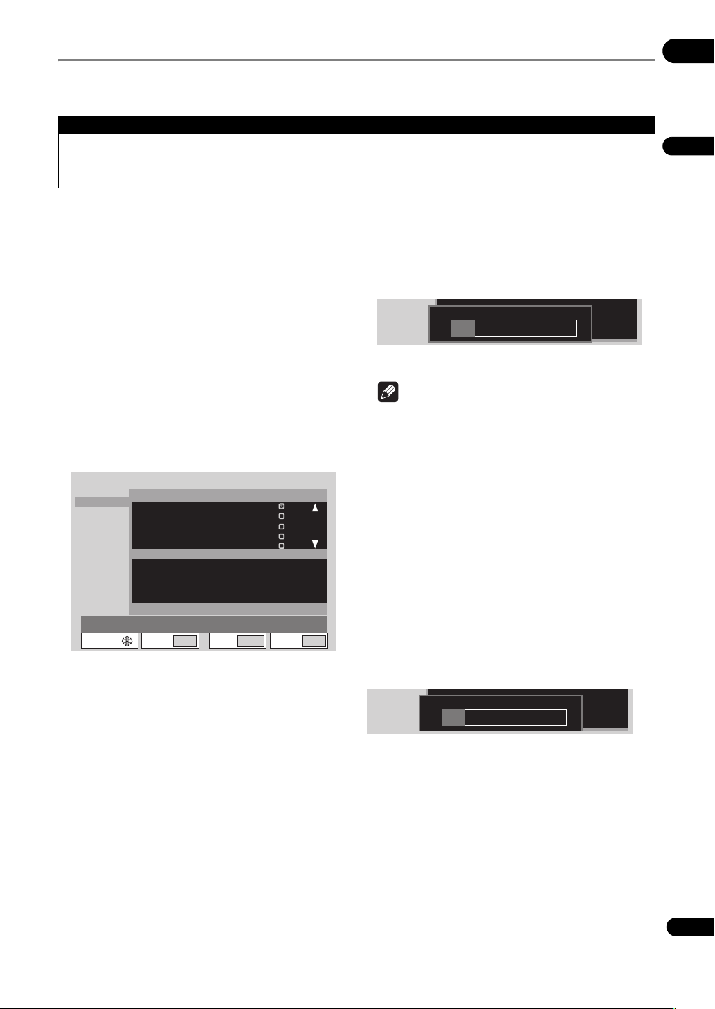
File management (File Management)
Use the procedure below to copy and delete files in the USB storage device’s root directory and in the video, picture
and text folders and to format SD memory cards.
• This procedure can only be performed when all units are in the playback stop mode.
Setting item Description
Copy Copies files.
Delete Deletes files.
Format Formats the SD memory card. Creates video, picture, text and system folders.
06
English
Copying/deleting files
1 Select the Copy or Delete setting item.
Use the / buttons to select, then press the ENTER
button.
2 Select the medium (USB or SD).
Use the / buttons to select, then press the ENTER
button.
• To copy/delete SD memory card files, also select
video, picture or text.
•The video, picture and text folders are always
displayed on the menu screen, even if they do not
exist on the SD memory card. The system folder is not
displayed.
3 Select the file to be copied or deleted.
Use the / buttons to select, then press the ENTER
button.
File Management
Copy
Delete
Format
Move Select
Media : USB
AAAAAAAAAA.mpg
BBBBBBBBB.mpg
CCCC.bmp
bmp
DDDDDDD.bmp
EEEEEE.mpg
Media : SD
Video
Picture
Text
ENTER
Return
RETURN
•A check mark appears in the check box on the right
side. The check mark is turned off when the ENTER
button is pressed again.
• To select more files, use the / buttons to select,
then press the ENTER button.
• When copying files from a USB storage device onto
an SD memory card, bitmap files (.bmp) are copied
into the picture folder, text files (.txt) into the text
folder. Files with other extensions are copied into the
video folder.
• When copying files from an SD memory card onto a
USB storage device, all the files are copied into the
root directory (page 22).
4 Display OK.
Press the button.
Exit
**/**
SETUP
5Select OK.
Press the ENTER button. The file(s) is (are) copied or
deleted. The progress is displayed as shown below.
• When CANCEL is selected with the / buttons
and the ENTER button is pressed, the procedure
returns to step 3.
Text
File Name : AAAAAAAAAA.set
001/000
Note
• Depending on the file size, some time may be
required for processing. Also, if there are many files,
some time may be required until the picture is
displayed. We recommend deleting any unnecessary
files beforehand.
Formatting SD memory cards
1 Select Format.
Use the / buttons to select, then press the ENTER
button.
• When Format is selected, the files stored in the
different folders on the SD memory card can be
checked before formatting by pressing the button
to select Media:SD then pressing the ENTER button.
2Select OK.
Use the / buttons to select, then press the ENTER
button. Formatting begins. The progress is displayed as
shown below.
Text
Media:SD
51
En
Page 52

Information Menu
06
Information display (System Information)
This displays the firmware version, the time for which the power has been on, information on this unit and connected
media, etc.
System Information
Player Information
Firmware Version
Serial No : JATW012345JP
Card Information
Format : Unknown
Protect
Total Capacity
• To display the firmware version on the main unit display, close the Setup screen, then while in the stop mode press
the DISPLAY button for over 1 second (page 43).
• The time displayed between brackets ([ ]) at Power On Time may return to [0], for example when it is reset by
Pioneer service personnel during maintenance.
• The last time the time was acquired from the NTP server (GMT) is displayed at NTP Last Update.
NTP Last Update is not displayed if the NTP setting is invalid or the time has not yet been acquired.
: 01.00
: 000123h35m[000123h35m]Power On Time
: HIDConnect USB
: Success 10-03-31 Wed 00:00:00NTP Last Update
: Yes
: 00.0 GB Used Capacity : 00.0 GB
Return
RETURN
Exit
SETUP
52
En
Page 53

Power On Start setting
This sets the operation after this unit is switched from the
status in which no power is being supplied to the status
in which power is supplied as well as the operation when
this unit’s power is turned on.
STANDBY/ON
SEARCH REPEAT MEMORY RECALL
OUTPUT
RESOLUTION
+
-
FRM
/TIME
DISPLAY
06
English
NAVI-
GATOR
SETUP RETURN
PLAY
MODE
1 Display the Play Mode screen.
Press the PLAY MODE button.
• The play mode screen can also be displayed by
selecting Play Mode from the Setup screen.
2 Select Power On Start.
Use the / buttons to select, then press the ENTER
button.
3 Select the setting.
Use the / buttons to select, then press the ENTER
button.
• Off – The standby mode is set when the power cord is
plugged into an outlet. Select this if you do not want
the power to turn on automatically.
• On – The power turns on when the power cord is
plugged into an outlet. Playback does not start
automatically.
• FilePlay – When the power is turned on, playback
automatically starts from the specified file. After this,
operation is the same as for normal playback.
• Playlist – When the power is turned on, playback
automatically starts from the specified playlist.
If FilePlay or Playlist is selected, select the file or playlist
to be played.
When started from the standby mode, the same operation
is performed whether this is set to Off or On.
53
En
Page 54

Chapter 7
07
Playlists
Playlists can also be created and edited using the HD
PILOT computer application. For details on HD PILOT, see
the Pioneer website.
Time map table files of the video files you want to play
must be created in advance using HD PILOT in order to
create playlists.
Creating playlists using the Simple Create
Use this function to easily create playlists for playing
video files continuously.
STANDBY/ON
SEARCH
REPEAT MEMORY RECALL
OUTPUT
RESOLUTION
+
-
DISPLAY
PLAY
MODE
NAVI-
GATOR
FRM
/TIME
3 Select the files you want to play.
Use / to select, then press ENTER. The specified file
is registered in the playlist. Repeat this procedure to
register more files.
Playlist
Playlist
Simple Create
**********.***
**********.***
**********.***
**********.***
**********.***
**********.***
**********.***
**********.***
**********.***
Move Select
Source 01/02 02/02List 01
ENTER
01
**********.***
02
Return
000m00s
000m00s
000m00s
000m00s
000m00s
000m00s
000m00s
000m00s
000m00s
RETURN
Exit
SETUP
4 Finish creating the playlist.
When SETUP or RETURN is pressed, a confirmation
screen appears. Use / to select OK, then press
ENTER. The playlist settings are saved.
• When SETUP is pressed, the Setup screen turns off.
• When RETURN is pressed, the unit returns to step 2.
• When CANCEL is selected, the unit returns to step 2
without saving the playlist settings.
• When RETURN is selected, the unit returns to step 3.
SETUP RETURN
1 Display the Setup menu.
Press the Setup button.
2 Select Playlist Simple Create Select.
Use /// to select, then press ENTER.
54
En
Note
• Up to 20 playlists can be registered.
• Up to 12 video files can be registered per playlist.
• Video files for which there is no time map table file
cannot be registered.
Changing the order of registered files
1 Display the Setup menu.
Press SETUP.
2 Select Playlist Simple Create Select.
Use /// to select, then press ENTER.
3 Select the file you want to move.
Use to move the cursor to the playlist. Use / to
select the file, then press ENTER. The menu appears.
4 Select Change Position.
Use / to select, then press ENTER. A bar appears.
Page 55

5 Set the bar to the position to which you want to
move the file.
Use / to select, then press ENTER.
000m00sAAAAAAAAA.mp
000m00s
000m00s
000m00s
000m00s
000m00s
000m00s
000m00s
000m00s
Playlist
ENTER
List 01
11.KKKKKKKKK.mpg
12.LLLLLLLLL.mpg
MMMMMMMMM
OOOOOOOOO
RETURN
.mpg
.mpg
Exit
13.
14.NNNNNNNNN.mpg
15.
16.FFFFFFFFF.mpg
17.
OK CANCEL RETURN
Return
Bar
SETUP
Simple Create
BBBBBBBBB.mp
CCCCCCCCC.mp
DDDDDDDDD.mp
EEEEEEEEE.mp
GGGGGGGGG.mp
HHHHHHHHH.mp
IIIIIIIII.mp
JJJJJJJJJ.mp
Move Select
Source 01/02 02/02
6Select OK.
Use / to select, then press ENTER. The selected file
is moved.
•When CANCEL is selected, the unit returns to step 3.
•When RETURN is selected, the unit returns to step 5.
Creating playlists using the Create/Edit
Use this function to create playlists for playing video, still
picture and character string files.
STANDBY/ON
SEARCH
REPEAT MEMORY RECALL
OUTPUT
RESOLUTION
+
-
DISPLAY
MODE
PLAY
NAVI-
GATOR
FRM
/TIME
07
English
Deleting registered files
1 Display the Setup menu.
Press SETUP.
2 Select Playlist Simple Create Select.
Use /// to select, then press ENTER.
3 Select the file you want to delete.
Use to move the cursor to the playlist. Use / to
select the file, then press ENTER. The menu appears.
4 Select Delete One or Delete All.
Use / to select, then press ENTER.
Select Delete One to delete the selected file, Delete All
to delete all the registered files.
5 Delete the file(s).
When the SETUP or RETURN button is pressed, a
confirmation screen appears. Use the / buttons to
select OK, then press the ENTER button. The file(s) is
(are) deleted.
– When the SETUP button is pressed, the Setup
screen turns off.
– When the RETURN button is pressed, the unit
returns to step 2.
– When CANCEL is selected, the unit returns to
step 2 without deleting the file(s).
– When RETURN is selected, the unit returns to
step 3.
SETUP RETURN
Basic Playlist Creation Screen
Type of playback or line
editing command
Line number File name
Playlist
Create/Edit
01 Fileplay
02
03
04
ST:000000 ET:000000List 01
OnePointPic
TBD
Fileplay
TBD
Type Select
List 02
List 03
Move Select
UsedList [01/20]
AAAAAAAAA.mpg
LLLLLLLLL.mpg
BBBBBBBBB.mpg
ENTER
Return
Playlists
Lines (individual files
registered in the list)
Amount of
memory used
Used Memory [
RETURN
Property
Property
Property
Exit
Property
(Settings for
playback)
]
%
***
SETUP
Property
contents
55
En
Page 56

Creating a new playlist
07
1 Display the Setup menu.
Press SETUP.
2 Select Playlist Create/Edit Select.
Use /// to select, then press ENTER. The basic
playlist creation screen appears.
• If not a single line is registered, press the button to
proceed to step 4.
3 Add a playlist.
Press ENTER. The command selection screen appears.
Use / to select Create List, then press ENTER. A new
playlist with the highest number is created.
4 Select the line number.
Use to select 01.
5 Set the type of playback.
Press , select Type Select, then press ENTER. The
settings screen appears. Use / to select the setting,
then press ENTER. For details on the settings, see
page 58.
6 Select the file to be played.
Use to select File Select, then press ENTER. The file
selection screen appears. Use / to select the file, then
press ENTER.
7 Set the details for playback.
Press , select Property, then press ENTER. The details
settings screen appears. Use /// to change the
settings, select OK, then press ENTER. For details on the
contents of the settings, see Property under Type Select
setting on page 58.
Playlist
Create/Edit
01 Fileplay
List 01
List 02
List 03
Property
Audio : Off
0
Video : On
0
Audio Adjust : +00 [dB]
Lip Sync : Off
0
Lip Sync Adjust : +00 [Frame]
Start :
0
End :
OK
Move Select
UsedList [01/20]
LLLLLLLLLL.mp
hms
00 00 00
hms
00 00 00
ENTER
Return
RETURN
• Once registration of a line is completed, Type Select
appears on the next line. Use / to select the next
line, then repeat steps 5 to 7.
8 Finish creating the playlist.
When SETUP or RETURN is pressed, a confirmation
screen appears. Use / to select OK, then press
ENTER. The playlist settings are saved.
•When the SETUP button is pressed, the Setup screen
turns off.
•When RETURN is pressed, the unit returns to step 2.
•When CANCEL is selected, the unit returns to step 2
without saving the playlist settings.
•When RETURN is selected, the unit returns to the
56
En
previous step.
Used Memory [
Property
Exit
***
SETUP
Note
• Up to 20 playlists can be registered.
• Up to 12 video files can be registered per playlist.
• The amount of memory used depends on the number
of files, playing time and type of playback. It is not
possible to set a playlist if the amount of memory
used exceeds 100%.
• The playback operation and file must be selected for
line registration to be completed.
• Video files for which there is no time map table file
cannot be registered.
Editing playlists
Use this procedure to edit existing playlists.
1 Display the Setup menu.
Press SETUP.
2 Select Playlist Create/Edit Select.
Use /// to select, then press ENTER. The basic
playlist creation screen is displayed.
3 Select the playlist.
Use / to select, then press .
4 Select the line you want to edit.
Use / to select.
5 Select the item you want to edit.
Use / to select, then press ENTER.
• When the line number is selected, the line editing
command selection screen appears. For details on
the contents of the settings, see page 59.
• When Type Select is selected, the Type Select
]
%
selection screen appears. For details, see page 58.
• When a file name is selected, the file selection screen
appears.
• When Property is selected, the details settings
screen appears. For details on the contents of the
settings, see pages 58 to 61.
6 Change the setting.
Use /// to change the settings, then press
ENTER.
7 Finish editing the playlist.
When SETUP or RETURN is pressed, a confirmation
screen appears. Use / to select OK, then press the
ENTER button. The playlist settings are saved.
• When SETUP is pressed, the Setup screen turns off.
• When RETURN is pressed, the unit returns to step 2.
• When CANCEL is selected, the unit returns to step 2
without saving the playlist settings.
• When RETURN is selected, the unit returns to the
previous step.
Page 57

Deleting playlists
1 Select the playlist.
Use / to select, then press ENTER.
2 Select Delete List.
Use / to select, then press ENTER.
Displaying still pictures superimposed over the video (Image Overlay)
Bitmap files created on the computer can be
superimposed over video images.
•Create a picture folder in the SD memory card’s root
directory and store the bitmap files in it in advance.
Connect the SD memory card to this unit before
registering the bitmap files in playlists.
• The video file must be registered in the playlist in
advance.
Caution
• The bitmap files below can be displayed.
Image size: 640 x 360
File format: Windows bitmap format (24-bit)
• On displays that have overscan, the edges of the
image may be cut off. If so, arrange the image so that
it fits within about 90% of the display’s inner area.
• Images cannot be overlaid during scrolling with the
Text Crawl function. If still within the image overlay
display time when scrolling stops, the overlay image
is displayed. Check the operation ahead of time.
• With the Text Crawl and Image Overlay functions, it is
not possible to display setting menus and the OSD
simultaneously. The setting menus and the OSD are
displayed with priority.
1 Display the Setup menu.
Press SETUP.
2 Select Playlist Create/Edit Select.
Use /// to select, then press ENTER. The basic
playlist creation screen is displayed.
3 Select the playlist.
Use / to select, then press .
4 Select the video file to be used as the main file.
Use the / buttons to select, then press the ENTER
button.
5 Select Add Image Overlay.
Use / to select, then press ENTER. For details of the
command, see page 59.
6 Play the playlist.
The still image is displayed over the video.
Displaying text superimposed over the video (Text Crawl)
Text files created on the computer with a text editor, etc.,
or text information such as news distributed by RSS sites
can be superimposed over video images.
• Create a text folder in the SD memory card’s root
directory and store the text files in it in advance
(page 22). Connect the SD memory card to this unit
before registering the text files in playlists.
• The video file must be registered in the playlist in
advance.
• For details about the RSS function, see About network
functions on page 70.
Caution
• Only text in “UTF-8” format can be displayed.
• When creating text files, store them with the
character code set to the “UTF-8” format.
• The Text Crawl start time is the time at which
preparations to display the text begin. Depending on
the text content and type (RSS/Text), there may be a
delay between the start time and the time the text is
displayed. Check the operation beforehand.
• When Moving Speed is set to Hold, the beginning of
the text will not be displayed on displays for which the
angle of view is 100% (page 60).
1 Display the Setup menu.
Press SETUP.
2 Select Playlist Create/Edit Select.
Use /// to select, then press ENTER. The basic
playlist creation screen is displayed.
3 Select the playlist.
Use / to select, then press .
4 Select the video file to be used as the main file.
Use the / buttons to select, then press the ENTER
button.
5 Select Add UserTextCrawl or Add RSSTextCrawl.
Use / to select, then press ENTER. For details of the
commands, see page 59.
6 Play the playlist.
The text is displayed over the video.
07
English
57
En
Page 58

About the maximum number of
07
characters
The number of characters displayed differs when
scrolling and when not scrolling. The number of
European characters (1-byte code) is calculated based on
the width of the letter “W”. This number includes spaces.
When scrolling text (rough indication)
Font size European characters Japanese/Korean
Min.
(30 dots)
Small
(35 dots)
Medium
(40 dots)
Large
(45 dots)
178 characters 136 characters
151 characters 117 characters
136 characters 102 characters
120 characters 91 characters
When not scrolling text (rough indication)
Font size European characters Japanese/Korean
Min.
(30 dots)
Small
(35 dots)
Medium
(40 dots)
Large
(45 dots)
24 characters 18 characters
21 characters 16 characters
19 characters 14 characters
16 characters 12 characters
characters
characters
Type Select setting
This sets the type of playback for a new line.
Caution
•Once Type Select is set, it cannot be changed. To
change it, first delete the line using the Delete Line
command, then reset the line.
File Play
Video files are played in units of files.
Property Setting Description
Audio On The audio is output.
Off The audio is not output.
Video On The video is output.
Off The video is not output.
Audio Adjust –10 to 00 The volume is decreased by the
Lip Sync On The audio’s delay time can be
Off The audio’s delay time is
Lip Sync
1
Adjust
Start Time ** h ** m ** s This sets the time for starting
End Time ** h ** m ** s This sets the time for stopping
1. The range that can be set at Lip Sync Adjust is –167 ms to
+267 ms, when converted into time. The setting range differs
according to the content’s frame rate.
–10 to 00 to
+16
set dB value for output.
fine-adjusted at Lip Sync
Adjust.
adjusted automatically.
The video is displayed the set
number of frames before the
audio.
playback. Input the time using
the number buttons.
playback. Input the time using
the number buttons.
58
En
Page 59

Frame Segment Play
Video files are played in units of frames.
Property Setting Description
Audio On The audio is output.
Off The audio is not output.
Video On The video is output.
Off The video is not output.
Audio Adjust –10 to 00 The volume is decreased by the
Lip Sync On The audio’s delay time can be
Off The audio’s delay time is
Lip Sync Adjust –10 to 00 to
Start Time ** h ** m ** s This sets the time for starting
End Time ** h ** m ** s This sets the time for stopping
Search Frame
Mark Frame
1. Set the interval betwee n Search Frame and Mark Frame to at least
31 frames.
1
1
+16
*******
(7-digit
number)
*******
(7-digit
number)
set dB value for output
fine-adjusted at Lip Sync
Adjust.
adjusted automatically.
The video is displayed the set
number of frames before the
audio.
playback. Input the time using
the number buttons.
playback. Input the time using
the number buttons.
This specifies the starting point
for the range to be played, in
frames. Input the point using
the number buttons.
This specifies the end point for
the range to be played, in
frames. Input the point using
the number buttons.
Repeat List
Playback starts from the first line in the playlist.
• Set this at the very last line.
•When Repeat Mode is set to On, the list is played
repeatedly, regardless of this Repeat List setting
(page 47).
Go to List
Playback starts from the first line in the playlist of the
specified number. Input the number using the number
buttons. Numbers 01 to 20 can be input.
• Set this at the very last line.
Note
• The time and number of frames changed at Property
is displayed in the Property contents display section.
Line editing commands
These are used to edit registered lines and add various
functions.
Caution
• The line editing commands cannot be edited once
registration of a line is completed.
Insert File Play
This inserts a command to play video files in units of files.
The video file selected at File Select is played from the
beginning according to the Property settings. For details
on the contents of the Property settings, see File Play
under Type Select setting on page 58.
Insert Frame Segment Play
This inserts a command to play video files in units of
frames. The video file selected at File Select is played
from the beginning of the frame specified at Property
settings. For details on the contents of the Property
settings, see Frame Segment Play under Type Select
setting on page 58.
Add Image Overlay
This plays the specified still picture file superimposed
over the video file according to the settings below.
Property Selection
Transparent
Color
Transparent
Rate
Start Time ** h ** m ** s This sets the time for starting
item
Black This sets black as the
White This sets white as the
Blue This sets blue as the
Green This sets green as the
Yellow This sets yellow as the
Red This sets red as the transparent
0% The specified still picture file’s
25% The specified still picture file’s
50% The specified still picture file’s
75% The specified still picture file’s
Description
transparent color for the
specified still picture file.
transparent color for the
specified still picture file.
transparent color for the
specified still picture file.
transparent color for the
specified still picture file.
transparent color for the
specified still picture file.
color for the specified still
picture file.
transparent color is not
transparent.
transparent color is slightly
transparent.
transparent color is half
transparent.
transparent color is quite
transparent.
playback. Input the time using
the number buttons.
07
English
59
En
Page 60

07
Property Selection
item
End Time ** h ** m ** s This sets the time for stopping
Description
playback. Input the time using
the number buttons.
Note
•When Add Image Overlay is registered, is
displayed at the right of the line number. This
indicates that the line is associated with the video file
on the list. If the video file is deleted, Image Overlay
is also deleted.
Add UserTextCrawl/Add
RSSTextCrawl
This plays the character string file (Text/RSS)
superimposed over the video file according to the settings
below.
Caution
• Pay attention to the copyrights of RSS content. In
particular, for RSS services distributing general
news, etc., permission of the distributor is required to
display the contents of articles.
Setting Description
1,2
URL
Property Selection
Text Line Line 1 The text is displayed at the very
Text Size Size 1 The text is displayed in
60
En
This sets the URL of the RSS site. See page 39
for instructions on inputting characters.
Description
item
bottom of the screen.
Line 2 The text is displayed at a height
approximately 1/5 the distance
from the bottom of the screen.
Line 3 The text is displayed at a height
approximately 1/3 the distance
from the bottom of the screen.
Line 4 The text is displayed at the
center of the screen.
Line 5 The text is displayed at a height
approximately 2/3 the distance
from the bottom of the screen.
Line 6 The text is displayed at a height
approximately 4/5 the distance
from the bottom of the screen.
Line 7 The text is displayed at the very
top of the screen.
minimum size.
Size 2 The text is displayed in small
size.
Size 3 The text is displayed in a size
between Size 2 and Size 4.
Size 4 The text is displayed in large
size.
Property Selection
Text Color Black The text is displayed in black.
Background
Color
Transparent
3
Rate
Moving Speed Hold The character string is fixed.
Start Time ** h ** m ** s This sets the time for starting
End Time ** h ** m ** s This sets the time for stopping
Select Tag1
Select Tag2
item
White The text is displayed in white.
Blue The text is displayed in blue.
Yellow The text is displayed in yellow.
Green The text is displayed in green.
Red The text is displayed in red.
Black The background is displayed in
White The background is displayed in
Blue The background is displayed in
Yellow The background is displayed in
Green The background is displayed in
Red The background is displayed in
0% The background color is not
25% The background color s slightly
50% The background color is half
75% The background color is quite
100% The background color is fully
Slow The character string moves
Normal The character string moves at
Fast The character string moves
1,4
None Not displayed.
<title> The article’s title information is
<description>
<author> The article’s copyright
1,4
None Not displayed.
<title> The article’s title information is
<description>
<author> The article’s copyright
Description
black.
white.
blue.
yellow.
green.
red.
transparent.
transparent.
transparent.
transparent.
transparent.
slowly.
normal speed.
quickly.
playback. Input the time using
the number buttons.
playback. Input the time using
the number buttons.
displayed.
A description of the article is
displayed.
information is displayed.
displayed.
A description of the article is
displayed.
information is displayed.
Page 61

Property Selection
Select Tag3
1. Set for RSS format character string files.
2. Ignored when a space is input.
3. When the transparency is set (to something other than 0%), the
characters may be hard to see.
4. The actual tag name depends on the RSS-compatible format.
item
1,4
None Not displayed.
<title> The article’s title information is
<description>
<author> The article’s copyright
Description
displayed.
A description of the article is
displayed.
information is displayed.
Playing playlists
STANDBY/ON
SEARCH
REPEAT MEMORY RECALL
OUTPUT
RESOLUTION
+
-
FRM
/TIME
DISPLAY
07
English
Note
•When Add UserTextCrawl and Add RSSTextCrawl
are registered, is displayed at the right of the line
number. This indicates that the line is associated with
the video file on the list. If a video file is changed or
deleted, UserTextCrawl and RSSTextCrawl are also
deleted.
Merge List
This combines the playlist with the following number to
the end of the playlist currently being edited. (Subsequent
playlist numbers are each shifted down one number.
Note that the Go To List numbers are not changed.)
Divide List
This registers another playlist after the currently selected
line. This playlist is registered with the number following
the number of the playlist currently being edited
(subsequent playlist numbers are each shifted up one
number).
Delete Line
This deletes the selected line.
NAVI-
GATOR
SETUP RETURN
PLAY
MODE
Note
• Playlist playback is canceled if the following
operations are performed while the playlist is playing:
–Playback stop
– Special playback commands (pause, fast-forward/
reverse, slow play, step forward/reverse, etc.)
– Time search/frame search
Playing in the desired order (Recall)
This functions allows you to specify the desired playlist
number and play it.
Caution
• Depending on the files and commands, it may not be
possible to play the playlist as it was registered.
Store the playlists you have created in advance on an SD
memory card or USB storage device, then load the stored
playlists into this unit before playing them (page 50).
1 Display the playlists.
Press RECALL.
• The playlists can also be displayed by selecting
Playlist Recall from the Setup screen.
61
En
Page 62

2 Select the playlist you want to play.
07
Use / to select.
• With playlists, it is possible to set the file playback
settings, etc., individually. Each of these settings is
called a line. The line can be checked by selecting the
playlist then pressing . Use / to move the
cursor. Playlists cannot be played while a line is being
checked.
3 Play the playlist.
Press ENTER. The playlist is played through the end of the
last registered line.
•When LCD on the main unit’s front panel is pressed
during playlist playback and the display is switched,
Playlist ** (number) is displayed on the main unit
display.
Power On Start
The specified playlist can be played automatically when
the power turns on. See page 53 for details.
Playing from an external device
This unit can be operated and played from an external
device via serial/LAN interface. See page 64 for details.
62
En
Page 63

Chapter 8
Schedules
08
Setting times for turning the power on and off automatically
The schedule function allows you to automatically turn
this unit’s power on and off, or play specific files or
playlists on specific dates or days of the week.
STANDBY/ON
SEARCH REPEAT MEMORY RECALL
OUTPUT
RESOLUTION
+
-
FRM
/TIME
NAVI-
GATOR
SETUP RETURN
Caution
• When using the schedule function, make sure the
time is properly set at Clock Setting (page 47).
• About one minute is required for this unit to start up.
Take this startup time into account when setting
schedules.
1 Display the Setup screen.
Press the SETUP button.
2 Select Play Menu Schedule Enable All.
Use the /// buttons to select, then press the
ENTER button.
• The schedule function will not work if Disable All is
selected.
3 Select Type.
Select the method for specifying the day the schedule
function will operate. Use the / buttons to select, then
press the ENTER button.
• Date – Specify the date.
• Day – Specify the day of the week.
4 Set the date or day of the week.
Use the / buttons to select, then press the button.
•If Date is selected at step 3, set the Month and Day.
•
If
Day
is selected at step 3, set the
DISPLAY
PLAY
MODE
Day
(day of the week).
5 Input the time.
For instructions on inputting, see Inputting numbers
(page 38).
• On – Input the time at which you want the power to
turn on.
• Off – Input the time at which you want the power to
turn off.
Caution
•To set the On and Off times on different days, register
the times in two different lines.
Example: (On) (Off)
1st line: 23:00 --:-2nd line: --:-- 02:00
6Select Mode.
Select the operation after the power turns on. Use the
/ buttons to select, then press the ENTER button.
• -- – Nothing is played when the power is turned on.
• File Play – The specified file is played.
• Playlist – The specified playlist is played.
7 Select Parameter.
•If File Play was selected at step 6, the setting is
completed when the file is selected using the /
buttons and the ENTER button is pressed.
•If Playlist was selected at step 6, the setting is
completed when the playlist number is selected using
the / buttons and the ENTER button is pressed.
To delete a schedule entry
Select the schedule entry you want to delete, then press
the CLEAR button.
To storing schedule entries
When the SETUP or RETURN button is pressed while the
Schedule screen is displayed, a confirmation screen
appears. Press OK then press the ENTER button to store
the entry.
• When the SETUP button has been pressed, the Setup
screen turns off.
• When the RETURN button has been pressed, the
procedure returns to step 2.
• When CANCEL is selected, the procedure returns to
step 2 without storing the entry.
• When RETURN is selected, the procedure returns to
the previous step.
Note
•The Schedule entry must include at least the Type,
Day and the On or Off time.
• Up to eight entries are displayed on the Schedule
screen. Use the /// buttons to switch pages.
• Up to 32 schedule entries can be registered.
English
63
En
Page 64

Chapter 9
09
Communications/Control
About the Communications Interface User’s Manual
For detailed information on the serial/LAN interface
commands, download the “HD-V9000 Communications
Interface User’s Manual” from the Pioneer website.
Serial interface specifications
This unit is equipped with a serial control interface
conforming to RS-232C standards, allowing it to be
connected to a computer with either a 9-pin or a 15-pin
D-Sub connector. The connector to be used can be
switched at Initial Settings Options Serial Port
(page 47).
Caution
• It is not possible to access the 9-pin and 15-pin
connectors simultaneously.
• Both the 9-pin connector and the 15-pin connector
use inch screw threads.
The connectors’ pin layouts are as shown below.
8
15-pin D-Sub connector
Pin no. Pin name Input/
1GND-- ground
2 TxD Output send data
3 RxD Input receive data
4 DTR Output enable data receiving
5 POWER Input external power control
6 SW1 Input Extend Terminal
7 SW2 Input Extend Terminal
8 SW3 Input Extend Terminal
9 SW4 Input Extend Terminal
10 SW5 Input Extend Terminal
11 SW6 Input Extend Terminal
12 SW7 Input Extend Terminal
13 SW8 Input Extend Terminal
14 NC -- NC (not connected on
64
15 STOP_ST Output Stop/Play Status
En
1
915
Output
6
Function
this unit)
9-pin D-Sub connector
Pin no. Pin name Input/
Output
1 DCD Input NC (not connected on
2 RxD Input receive data
3 TxD Output send data
4 DTR Output enable data receiving
5GND-- Ground
6 DSR Input NC (not connected on
7 RTS Output Connected internally to
8 CTS Input Connected internally to
9 RI Input NC (not connected on
Function
this unit)
this unit)
CTS
RTS
this unit)
Control functions
(a) Serial control
TxD, RxD and DTR
Serial control interface conforming to RS-232C
standards.
(b) Extend terminals
SW1, SW2, SW3, SW4, SW5, SW6, SW7 and SW8
This unit can be controlled by connecting switches to the
51
9
exterior of these pins.
(c) External power supply control
This unit’s power can be turned on and off using the
interface connector’s power pin.
Power off control is not possible when operation of the
buttons on the main unit’s front panel or remote control
unit is locked.
• When power is off (in the standby mode): Power
turns on when L signal detected after H signal of
100 msec or greater
• When power is on: Power turns off (to the standby
mode) when L signal detected after H signal of
100 msec or greater
Pin input voltage: ±12 V or less; H signal level: 4.5 V or
higher, L signal level: 0.5 V or lower
Page 65

(d) Playback status output
This unit’s operating status (playing/stopped) can be
detected with the interface connector’s STOP_ST pin.
There are two output modes, settable by command.
(1) Stop status detection mode
When in stop mode “L” is output
When in any other mode “H” is output
(2) Play status detection mode (default)
When in play mode “L” is output
When in any other mode “H” is output
The output is of the open collector type, so pull the voltage
up to a maximum of 12 V (50 mA).
Serial control specifications
(1) Signal level
RS-232C level
(2) Data format
Data length: 8 bits
Stop bits: 1 bit
Parity: None
(3) Communications speed (baud rate)
The communications speed (baud rate) can be selected
from among 2400, 4800, 9600 or 19200 bps. Upon
purchase it is set to 9600 bps (page 47).
Connection to a computer
LAN interface specifications
This unit is equipped with a LAN terminal. It can also be
controlled via LAN cable.
The connector’s pin layout is as shown below.
Modular jack (conforming to RJ-45 standards)
Pin No. Pin Name Input/Output Function
1 TD+ Output LAN line TX+
2 TD– Output LAN line TX–
3 RD+ Input LAN line RX+
4NC
5NC
6 RD– Input LAN line RX–
7NC
8NC
Control specifications
TD+, TD–, RD+, RD–
Ethernet interface conforming to 10BASE-T and
100BASE-TX standards.
(1) Control by same commands as for serial control
See Commands and statuses on page 66.
(2) Wake Up On LAN (remote power control)
(page 70)
09
English
This unit communicates with the computer using pins 2
and 3 of the 9- or 15-pin D-Sub connector for signal
transfer. Pin 5 of the 9-pin connector or pin 1 of the 15-pin
connector is used as the ground.
The computer and set are connected as shown on the
diagram below.
Computer HD-V9000
TxD RxD
RxD TxD
GND GND
This unit can accept commands whenever the power is
on. In addition, it can receive the Power On command
even when the power is off (in the standby mode).
There is no need to connect control lines other than TxD
and RxD.
65
En
Page 66

Commands and
09
statuses
Serial/LAN interface control is performed by the
computer, etc., sending commands and the player
returning the status. When command execution is fully
completed, this unit returns a completion message
(R<CR>). If an error is generated, this unit returns the
error code (for example, E04<CR>).
List of usable commands
No. Mnemonics Command Name
1 RJ Reject
2SA Start
(adrs) PL
(adrs) MF
(adrs) MR
1
Play
1
Multi-Speed Forward
1
Multi-Speed Reverse
3
4PA Pause
5 ST Still
6 SF Step Forward
7 SR Step Reverse
8NF Scan Forward
9 NR Scan Reverse
10 NS Scan Stop
11
12
13 arg SP Speed
14 adrs SE Search
15 adrs SL Search & Play
16 adrs SM Stop Marker
17 LO Lead Out Symbol
18 CL Clear
19 FR Frame
20 TM Time
21 arg AU Select Audio
22 arg AP Select Aspect
23 arg VD Video Control
24 arg DS Display Control
25 arg RF Output Resolution Set
26 arg KL Keylock
27 arg GP Playlist Number Set
28 BU Playlist Data Upload
29 BD Playlist Data Download
30 WU Schedule Data Upload
31 WD Schedule Data Download
32 GS Setup Data Upload
33 PS Setup Data Download
34 RM Repeat Mode
35 arg SK File Skip
36 FI File Name Input
37 arg TD Text Crawl Display
38 TK Text Crawl Display Off
66
En
No. Mnemonics Command Name
39 arg OD Image Overlay On
40 OE Image Overlay Off
41 FD File Delete
42 FC File Copy
43 PN
(arg) PF
(arg) RB
1
44
45
46 ?D File Information Request
47 ?R File Name Request
48 ?T Time Code Request
49 ?F Frame Number Request
50 ?Y Total Frame Request
51 arg RA Register A Set (Display)
52 arg RD Register D Set (TxD Term)
53 arg PR Print Character
54 CS Clear Screen
55 WW Real Time Clock Set
56 arg CM Communication Control Set
57 ?P Player Active Mode Request
58 ?L Player Model Number Request
59 ?X Player Model Name Request
60 ?W Real Time Clock Request
61 ?M CCR Mode Request
62 ?N Input Number Request
63 ?E Error Code Request
64 #I Input Unit Request
65 $A Register A Request
66 $D Register D Request
67 ?Z Firmware Version Request
68 ?O System Property Request
69 ?B File List Request
70 >A ~ >Z General Purpose Register Set
71 _A ~ _Z General Purpose Register Reference
72 <A ~ <Z General Purpose Register Read
73 ?U NTP Status Request
74 arg SS 15pin Status Set
75 #S 15pin Status Request
76 EL Error Log Upload
1. (adrs) and (arg) can be omitted.
2. Serial control only.
Power On
Power Off
1
Reboot
2
Page 67

Command mnemonics
Command mnemonics consist of two-digit ASCII
alphabetic coded characters. Uppercase and lowercase
characters can be used without distinction.
Setting the extend terminal button functions
09
Arguments
(1) Arguments are placed in front of the command.
If a command requiring an argument has no
argument, an error is generated.
(2) Arguments are of the following types:
1. Address:
The address consists of ASCII digit characters for the
frame number and time code, according to the
address mode.
The address mode is determined by the FR and TM
commands.
If a value greater than the maximum value is
attributed, the command will not work normally.
2. Argument:
The argument expresses a parameter for commands
with arguments other than the address (KL, GP, DS,
etc.).
The argument consists of ASCII alphabetic coded
characters and digit characters.
“Extend Terminal” refers to the function for controlling
this unit by turning the switch of a device connected to
the EXT TERMINAL connector on the main unit’s rear
panel on and off.
• SW1 to SW8 on the EXT TERMINAL connector on the
main unit’s rear panel are pulled up to +3.3 V. Assign
functions to combinations of SW1 to SW8.
• For the pin layout, see page 64.
• A maximum of 56 switches can be connected by
combining SW1 to SW8.
• For the switch combinations and functions assigned
upon purchase, see page 69.
1 Display the Setup screen.
Press the SETUP button.
2 Select Initial Settings Options Extend
Terminal User.
Use the /// buttons to select, then press the
ENTER button.
Initial Settings
Currrent (1-30)
01.
02.
03.
04.
05. ENTER
06. LIST01
07. LIST02
08. LIST03
09. LIST04
10. LIST05
LIST01
LIST02
LIST03
LIST04
LIST05
LIST06
LIST07
LIST08
LIST09
LIST10
LIST11
LIST12
LIST13
LIST14
LIST15
LIST16
LIST17
LIST18
LIST19
LIST20
PLAY
PAUSE
STOP
STEP FWD
STEP REV
SCAN FWD
SCAN REV
NEXT
PREV
DISPLAY
English
67
En
Page 68

09
R
R
• The newly assignable functions are as shown below.
Cursor
(four keys)
ENTER RECALL
PLAY SETUP
PAUSE MEMORY
STOP REPEAT
STEP FWD FRM/TIME
Operations
(22 keys)
STEP REV CLEAR
RETURN DISPLAY
SCAN FWD PLAY MODE
SCAN REV NAVIGATOR
NEXT RES. +
(OUTPUT RESOLUTION +)
PREV RES. –
(OUTPUT RESOLUTION –)
Numbers
0 – 9
(10 keys)
List (20 keys) LIST1 – 20
3 Select the button to be newly assigned.
Use the /// buttons to select, then press the
ENTER button.
• The display in the Current column changes to the
newly assigned function.
• It is also possible to set multiple switches to the same
function.
• Press the RETURN button to return to the Setup
screen.
• Press the SETUP button to close the Extend
Terminal screen.
Connection to a controller (switch interface)
The following shows an example of the connection
between a controller and this unit.
When not using a diode matrix
Fewer switches can be assigned (fewer functions can be
used).
SW1
SW2
SW3
SW4
SW5
SW6 LIST 1
SW7 LIST
SW8 LIST
When using a diode matrix (partial)
Up to 56 switches can be assigned.
SW1
SW2
SW3
SW4
SW5
SW6 LIST 1
SW7 LIST
SW8 LIST 3
ENTE
2
3
ENTE
1
2
3
4
5
6
7
8
9
2
To disable this unit’s functions
Use the / buttons to select the function you want to
disable in the Current column, then press the CLEAR
button. The display switches to Nothing.
To restore to the settings upon
purchase
Use the / buttons to select Default Setting in the
Current column, then press the ENTER button.
68
En
Note
• Specifications of switch used in this example
– Contact resistance: 1 Ω or less
– Insulation resistance: 1 MΩ or more
–Non-lock type
• Specifications of diode used in this example
– Forward voltage (VF): 0.7 V or less (IF 1 mA)
– Surge current: 100 mA or less
– Forward current: 10 mA or less (VR = 10 V)
• Serial command control is required for synchronized
playback of this unit by frame precision.
Synchronized playback by frame precision is not
possible with parallel control or control by remote
control.
Page 69

Settings upon purchase
09
The switch combinations and functions assigned upon purchase are shown below. Combinations and functions 1 to
30 can be changed at will (page 67).
• 1: Indicates that the switch is in the on status.
• Nothing: Indicates that the switch is in the off status.
No. SW1 SW2 SW3 SW4 SW5 SW6 SW7 SW8 Function
11
21
31
41
51 ENTER
61LIST 1
71LIST 2
81LIST 3
9111 LIST 4
10 1 1 1 LIST 5
11 1 1 1 LIST 6
12 1 1 1 LIST 7
13111 LIST 8
14 1 1 PLAY
15 1 1 PAUSE
16 1 1 STOP
17 1 1 RES. + (OUTPUT RESOLUTION +)
18 1 1 RES. – (OUTPUT RESOLUTION –)
19 1 1 NAVIGATOR
20 1 1 PLAY MODE
21 1 1 1 0
22 1 1 1
23 1 1 2
24 1 1 3
25 1 1 4
26 1 1 5
27 1 1 6
28 1 1 7
29 1 1 8
30 1 1 9
31 111 STEP FWD
32 1 1 1 STEP REV
33 1 1 1 RETURN
34 1 1 1 SCAN FWD
35 1 1 1 SCAN REV
36 1 1 1 NEXT
37 1 1 1 PREV
38 1 1 1 LIST 9
39 1 1 1 LIST 10
40 1 1 1 LIST 11
41 1 1 1 LIST 12
42 1 1 1 LIST 13
English
69
En
Page 70

09
No. SW1 SW2 SW3 SW4 SW5 SW6 SW7 SW8 Function
43 1 1 1 LIST 14
44 1 1 1 LIST 15
45 1 1 1 LIST 16
46 1 1 1 LIST 17
47 1 1 1 LIST 18
48 1 1 1 LIST 19
49 1 1 1 LIST 20
50 1 1 1 RECALL
51 1 1 1 SETUP
52 1 1 1 MEMORY
53 1 1 1 REPEAT
54 1 1 1 FRM/TIME
55 1 1 1 CLEAR
56 1 1 DISPLAY
About network functions
This unit can be connected to a network (LAN) to use the
functions below.
For details of the functions below, download the
“HD-V9000 Communications Interface User’s Manual”
from the Pioneer website.
–Wake Up On LAN
– Remote monitoring
– Command control by LAN
For details of the function below, download “HD PILOT”
from the Pioneer website and view its help file.
– Remote monitoring
Wake Up On LAN
This is a function for turning on this unit’s power via a
LAN. This unit’s Wake Up On LAN setting to must be set
to On (page 49).
FTP
This is a function for transferring video or still picture files
to the SD memory card or USB storage device connected
to this unit via the LAN. To use it, the FTP items at this
unit’s Network Settings setting must be set (page 49).
Remote monitoring
This is a function for monitoring this unit’s status
remotely. To use it, this unit’s Remote Port setting must
be set (page 49).
RSS
This function is for accessing RSS sites to display text
information (news, etc.) on the screen (Text Crawl).
Check the format of the data distributed by the RSS site.
This unit supports the formats below.
Supported formats: RSS 1.0, RSS 2.0 and Atom
Caution
• A separate contract with/payment to an Internet
service provider is required to use RSS and NTP
services over the Internet.
Command control by LAN
This function is for controlling this unit using the LAN
with the same commands as for serial control (page 65).
NTP
This function is for automatically accessing an NTP
server via LAN to acquire the time information and set
this unit’s time. An Internet connection is required
(page 49).
70
En
Page 71

Settings required for network functions
Before using the network functions, check the related network settings and change them as necessary (page 49).
: Required : As necessary : Not required
Setting item Setting value Network function
Remote
monitoring
Network Connection Disable/Enable
Type Auto IP/DHCP/
Manual
IP Address
Subnet Mask
Default Gateway
Primary DNS
Secondary DNS
Wake Up On LAN Off/On
Mac AddressDisplay only ––––––
FTP Username
FTP Password
FTP Port
Remote Port
Proxy Address
Proxy Port
NTP Disable/Enable
NTP Server Address
Time Zone GMT ± **:**
Wake Up On
LAN
FTP
operations
Command
control by
LAN
NTP RSS
09
English
71
En
Page 72

Chapter 10
10
Others/Troubleshooting
3. All advertising materials mentioning features or use of this software must display the
Updating the firmware
There are three ways to update the firmware: using an SD
memory card, using a USB storage device or using an
FTP server.
For concrete instructions on updating the firmware, see
the documentation included with the firmware to be
updated.
Licenses
The following shows the licenses for the software used in
this unit.
OpenSSL
The OpenSSL toolkit stays under a dual license, i.e. both the conditions of the OpenSSL
License and the original SSLeay license apply to the toolkit.
See below for the actual license texts. Actually both licen ses are BSD-style Open Source
licenses. In case of any license issues related to OpenSSL please contact opensslcore@openssl.org.
OpenSSL License
Copyright © 1998-2007 The OpenSSL Project. All rights reserved.
Redistribution and use in source and binary forms, with or without modification, are
permitted provided that the following conditions are met:
1. Redistributions of source code must retain the above copyright notice, this list of
conditions and the following disclaimer.
2. Redistributions in binary form must reproduce the above copyright notice, this list of
conditions and the following disclaimer in the documentation and/or other materials
provided with the distribution.
3. All advertising materials mentioning features or use of this software must display the
following acknowledgment: “This product includes software developed by the
OpenSSL Project for use in the OpenSSL Toolkit. (http://www.openssl.org/)”
4. The names “OpenSSL Toolkit” and “OpenSSL Project” must not be used to endorse or
promote products derived from this software without prior written permission. For
written permission, please contact openssl-core@openssl.org.
5. Products derived from this software may not be called “OpenSSL” nor may “O penSSL”
appear in their names without prior wr itten permission of the OpenSSL Project.
6. Redistributions of any form whatsoever must retain the following acknowledgment:
“This product includes software developed by the OpenSSL Project for use in the
OpenSSL Toolkit (http://www.openssl.org/)”
THIS SOFTWARE IS PROVIDED BY THE OpenSSL PROJECT “AS IS” AND ANY
EXPRESSED OR IMPLIED WARRANTIES, INCLUDING, BUT NOT LIMITED TO, THE
IMPLIED WARRANTIES OF MERCHANTABILITY AND FITNESS FOR A PARTICULAR
PURPOSE ARE DISCLAIMED. IN NO EVENT SHALL THE OpenSSL PROJECT OR ITS
CONTRIBUTORS BE LIABLE FOR ANY DIRECT, INDIRECT, INCIDENTAL, SPECIAL,
EXEMPLARY, OR CONSEQUENTIAL DAMAGES (INCLUDING, BUT NOT LIMITED TO,
PROCUREMENT OF SUBSTITUTE GOODS OR SERVICES; LOSS OF USE, DATA, OR
PROFITS; OR BUSINESS INTERRUPTION) HOWEVER CAUSED AND ON ANY THEORY
OF LIABILITY, WHETHER IN CONTRACT, STRICT LIABILITY, OR TORT (INCLUDING
NEGLIGENCE OR OTHERWISE) ARISING IN ANY WAY OUT OF THE USE OF THIS
SOFTWARE, EVEN IF ADVISED OF THE POSSIBILITY OF SUCH DAMAGE.
This product includes cryptographic software written by Eric Young
(eay@cryptsoft.com).This product includes software written by Tim Hudson
(tjh@cryptsoft.com).
Original SSLeay License
Copyright © 1995-1998 Eric Young (eay@cryptsoft.com)
All rights reserved.
This package is an SSL implementation written by Eric Young (eay@cryptsoft.com). The
implementation was written so as to conform with Netscapes SSL.
This library is free for commercial and non-commercial use as long as the following
conditions are aheared to. The following conditions apply to all code found in this
distribution, be it the RC4, RSA, lhash, DES, etc., code; not just the SSL code. The SSL
documentation included with this distribution is covered by the same copyright terms
except that the holder is Tim Hudson (tjh@cryptsoft.com).
Copyright remains Eric Young’s, and as such any Copyright notices in the code are not to
be removed. If this package is used in a product, Eric Young should be given attribution
as the author of the parts of the library used. This can be in the form of a textual message
at program startup or in documentation (online or textual) provided with the package.
Redistribution and use in source and binary forms, with or without modification, are
permitted provided that the following conditions are met:
1. Redistributions of source code must retain the copyright notice, this list of conditions
and the following disclaimer.
2. Redistributions in binary form must reproduce the above copyright notice, this list of
conditions and the following disclaimer in the documentation and/or other materials
provided with the distribution.
72
En
following acknowledgemen t: “This product includes cryptographic softwar e written by
Eric Young (eay@cryptsoft.com)”
The word ‘cryptographic’ can be left out if the rouines from the library being used are
not cryptographic related :-).
4. If you include any Windows specific code (or a derivative thereof) from the apps
directory (application code) you must include an acknowledgement: “This product
includes software written by Tim Hudson (tjh@cryptsoft.com)”
THIS SOFTWARE IS PROVIDED BY ERIC YOUNG “AS IS” AND ANY EXPRESS OR
IMPLIED WARRANTIES, INCLUDING, BUT NOT LIMITED TO, THE IMPLIED
WARRANTIES OF MERCHANTABILITY AND FITNESS FOR A PARTICULAR PURPOSE
ARE DISCLAIMED. IN NO EVENT SHALL THE AUTHOR OR CONTRIBUTORS BE LIABLE
FOR ANY DIRECT, INDIRECT, INCIDENTAL, SPECIAL, EXEMPLARY, OR
CONSEQUENTIAL DAMAGES (INCLUDING, BUT NOT LIMITED TO, PROCUREMENT OF
SUBSTITUTE GOODS OR SERVICES; LOSS OF USE, DATA, OR PROFITS; OR BUSINESS
INTERRUPTION) HOWEVER CAUSED AND ON ANY THEORY OF LIABILITY, WHETHER IN
CONTRACT, STRICT LIABILITY, OR TORT (INCLUDING NEGLIGENCE OR OTHERWISE)
ARISING IN ANY WAY OUT OF THE USE OF THIS SOFTWARE, EVEN IF ADVISED OF THE
POSSIBILITY OF SUCH DAMAGE.
The licence and distribution terms for any publically available version or derivative of this
code cannot be changed. i.e. this code cannot simply be copied and put under another
distribution licence [including the GNU Public Licence.]
zlib
This software is based in part on zlib see http://www.zlib.net for information.
SunRPC
Sun RPC is a product of Sun Microsystems, Inc. and is provided for unrestricted use
provided that this legend is included on all tape media and as a part of the software
program in whole or part. Users may copy or modify Sun RPC witho ut charge, but are not
aut hor ize d to lice nse or d istr ibu te i t to anyo ne e lse exc ept a s pa rt o f a p rodu ct o r pr ogr am
developed by the user.
SUN RPC IS PROVIDED AS IS WITH NO WARRANTIES OF ANY KIND INCLUDING THE
WARRANTIES OF DESIGN, MERCHANTIBILITY AND FITNESS FOR A PARTICULAR
PURPOSE, OR ARISING FROM A COURSE OF DEALING, USAGE OR TRADE PRACTICE.
Sun RPC is provided with no support and without any obligation on the part of Sun
Microsystems, Inc. to assist in its use, correction, modification or enhancement.
SUN MICROSYSTEMS, INC. SHALL HAVE NO LIABILITY WITH RESPECT TO THE
INFRINGEMENT OF COPYRIGHTS, TRADE SECRETS OR ANY PATENTS BY SUN RPC OR
ANY PART THEREOF.
In no event will Sun Microsystems, Inc. be liable for any lost revenue or profits or other
special, indirect and consequential damages, even if Sun has been advised of the
possibility of such damages.
Sun Microsystems, Inc.
2550 Garcia Avenue
Mountain View, California 94043
The BSD License
Copyright (c) 1998, Regents of the University of California
All rights reserved.
Redistribution and use in source and binary forms, with or without modification, are
permitted provided that the following conditions are met:
Redistributions of source code must retain the above copyright notice, this list of
conditions and the following disclaimer.
Redistributions in binary form must reproduce the above copyright notice, this list of
conditions and the following disclaimer in the documentation and/or other materials
provided with the distribution.
Neither the name of the <ORGANIZATION> nor the names of its contributors may be
used to endorse or promote products derived from this software without specific prior
written permission.
THIS SOFTWARE IS PROVIDED BY THE COPYRIGHT HOLDERS AND CONTRIBUTORS
“AS IS” AND ANY EXPRESS OR IMPLIED WARRANTIES, INCLUDING, BUT NOT LIMITED
TO, THE IMPLIED WARRANTIES OF MERCHANTABILITY AND FITNESS FOR A
PARTICULAR PURPOSE ARE DISCLAIMED. IN NO EVENT SHALL THE COPYRIGHT
HOLDER OR CONTRIBUTORS BE LIABLE FOR ANY DIRECT, INDIRECT, INCIDENTAL,
SPECIAL, EXEMPLARY, OR CONSEQUENTIAL DAMAGES (INCLUDING, BUT NOT
LIMITED TO, PROCUREMENT OF SUBSTITUTE GOODS OR SERVICES; LOSS OF USE,
DATA, OR PROFITS; OR BUSINESS INTERRUPTION) HOWEVER CAUSED AND ON ANY
THEORY OF LIABILITY, WHETHER IN CONTRACT, STRICT LIABILITY, OR TORT
(INCLUDING NEGLIGENCE OR OTHERWISE) ARISING IN ANY WAY OUT OF THE USE OF
THIS SOFTWARE, EVEN IF ADVISED OF THE POSSIBILITY OF SUCH DAMAGE.
Page 73

GNU GENERAL PUBLIC LICENSE
Version 2, June 1991
Copyright © 1989, 1991 Free Software Foundation, Inc., 51 Franklin Street, Fifth Floor,
Boston, MA 02110-1301 USA
Everyone is permitted to copy and distribute verbatim copies of this license document,
but changing it is not allowed.
Preamble
The licenses for most software are designed to take away your freedom to share and
change it. By contrast, the GNU General Public License is intended to guarantee your
freedom to share and change free software - to make sure the software is free for all its
users. This General Public License applies to most of the Free Software Foundation’s
software and to any other program whose authors commit to using it. (Some other Free
Software Foundation software is covered by the GNU Lesser General Public License
instead.) You can apply it to your programs, too.
When we speak of free software, we are referring to freedom, not price. Our General
Public Licenses are designed to make sure that you have the freedom to distribute copies
of free software (and charge for this service if you wish), that you receive source code or
can get it if you want it, that you can change the software or use piec es of it in new free
programs; and that you know you can do these things.
To pro tect your rights, we need to ma ke restri ctions tha t forbid a nyone to de ny you the se
rights or to ask you to surrender the rights. These restrictions translate to certain
responsibilities for you if you distribute copies of the software, or if you modify it.
For example, if you distribute copies of such a program, whether gratis or for a fee, you
must give the recipients all the rights that you have. You must make sure that they, too,
receive or can get the source code. And you must show them these terms so they know
their rights.
We protect your rights with two steps: (1) copyright the software, and (2) offer you this
license which gives you legal permission to copy, distribute and/or modify the software.
Also, for each author’s protection and ours, we want to make certain that everyone
unde rstan ds that there i s no wa rranty for thi s free s oftwar e. If th e soft ware is modifi ed by
someone else and passed on, we want its recipients to know that what they have is not
the original, so that any problems introduced by others will not reflect on the original
authors’ reputations.
Finally, any free program is threatened constantly by software patents. We wish to avoid
the danger that redistributors of a free program will individually obtain patent licenses, in
effect making the program proprietary. To prevent this, we have made it clear that any
patent must be licensed for everyone’s free use or not licensed at all.
The precise terms and conditions for copying, distribution and modification follow.
TERMS AND CONDITIONS FOR COPYING, DISTRIBUTION AND MODIFICATION
0. This License applies to any program or other work which contains a notice placed by
the copyright holder saying it may be distributed under the terms of this General Public
License. The “Program”, below, refers to any such program or work, and a “work based
on the Program” means either the Program or any derivative work under copyright law:
that is to say, a work containing the Program or a portion of it, either verbatim or with
modifications and/or translated into another language. (Hereinafter, translation is
included without limitation in the term “modification”.) Each licensee is addressed as
“you”.
Activities other than copying, distribution and modification are not covered by this
License; they are outside its scope. The act of running the Program is not restricted,
and the output from the Program is covered only if its contents constitute a work ba sed
on the Program (independent of having been made by running the Program). Whether
that is true depends on what the Program does.
1. You may copy and distribute verbatim copies of the Program’s source code as you
receive it, in any medium, provided that you conspicuously and appropriately publish
on each copy an appropriate copyright notice and disclaimer of warranty; keep intact
all the notices that refer to this License and to the absence of any warranty; and give
any other recipients of the Program a copy of this License along with the Program.
You may charge a fee for the physical act of transferring a copy, and you may at your
option offer warranty protection in exchange for a fee.
2. You may modify you r copy or copies of the Program or any portion of it, thu s forming a
work based on the Program, and copy and distribute such modifications or work under
the terms of Section 1 above, provided that you also meet all of these conditions:
a) You must cause the modified files to carry prominent notices stating that you
changed the files and the date of any change.
b) You must cause any work that you distribute or publish, that in whole or in part
co nta in s or is d er ive d fr om the Pr ogr am or a ny p ar t th ere of , to be lic ens ed as a wh ole
at no charge to all third parties under the terms of this License.
c) If the modified program normally reads commands interactively when run, you must
cause it, when started running for such interactive use in the most ordinary way, to
print or display an announcement including an appropriate copyright notice and a
notice that there is no warranty (or else, saying that you provide a warranty) and th at
users may redistribute the program under these conditions, and telling the user how
to view a copy of this License. (Exception: if the Program itself is interactive but does
not normally print such an announcement, your work based on the Program is not
required to print an announcement.)
These requirements apply to the modified work as a whole. If identifiable sections of
that work are not derived from the Program, and can be reasonably considered
independent and separate works in themselves, then this License, and its terms, do not
apply to those sections when you distribute them as separate works. But when you
distribute the same sections as part of a whole which is a work based on the Program,
the distribution of the whole must be on the terms of this License, whose permissions
for other licensees extend to the entire whole, and thus to each and every part
regardless of who wrote it.
Thus, it is not the intent of this section to claim rights or contest your rights to work
written entirely by you; rather, the intent is to exercise the right to control the
distribution of derivative or collective works based on the Program.
In addition, mere aggregation of another work not based on the Program with the
Program (or with a work based on the Program ) on a volume of a storage or distribution
medium does not bring the other work under the scope of this License.
3. You may copy and distribute the Program (or a work based on it, under Section 2) in
object code or executable form under the terms of Sections 1 and 2 above provided that
you also do one of the following:
a) Accompany it with the complete corresponding machine-readable source code,
which must be distributed under the terms of Sections 1 and 2 above on a medium
customarily used for software interchange; or,
b) Accompany it with a written offer, valid for at least three years, to give any third party,
for a charge no more than your cost of physically performing source distribution, a
complete machine-readable copy of the corresponding source code, to be
distributed under the terms of Sections 1 and 2 above on a medium customarily
used for software interchange; or,
c) Accompany it with the information you received as to the offer to distribute
corresponding source code. (This alternative is allowed only for noncommercial
distribution and only if you received the program in object code or executable form
with such an offer, in accord with Subsection b above.)
The source code for a work means the preferred form of the work for making
modifications to it. For an executable wo rk, complete source code means all the source
code for all modules it contains, plus any associated interface definition files, plus the
scripts used to control compilation and installation of the executable. However, as a
special exception, the source code distributed need not include anything that is
normally distributed (in either source or binary form) with the major components
(compiler, kernel, and so on) of the operating system on which the executable runs,
unless that component itself accompanies the executable.
If distribution of executable or object code is made by offering access to copy from a
designated place, then offering equivalent access to copy the source code from the
same place counts as distribution of the source code, even though third parties are not
compelled to copy the source along with the object code.
4. You may not copy, modify, sublicense, or distribute the Program except as expressly
provided under this License. Any attempt otherwise to copy, modify, sublicense or
distribute the Program is void, and will automatically terminate your rights under this
License. However, parties who have received copies, or rights, from you under this
License will not have their licenses terminated so long as such parties remain in full
compliance.
5. You are not required to accept this License, since you have not signed it. However,
nothing else grants you permission to modify or distribute the Program or its derivative
works. These actions are pr ohibited by law if you do not accept this License. Theref ore,
by modifying or distributing the Program (or any work based on the Program), you
indicate your acceptance of this License to do so, and all its terms and conditions for
copying, distributing or modifying the Program or works based on it.
6. Each time you redistribute the Program (or any work based on th e Program), the
recipient automatically receives a license from the original licensor to copy, distribute
or modify the Program subject to these terms and conditions. You may not impose any
further restrictions on the recipients’ exercise of the rights granted herein.
You are not responsible for enforcing compliance by third parties to this License.
7. If, as a consequence of a court judgment or allegation of patent infringement or for any
other reason (not limited to patent issues), conditions are imposed on you (whether by
court order, agreement or otherwise) that contradict the conditions of this License,
they do not excuse you from the conditions of this License. If you cannot distribute so
as to satisfy simultaneously your obligations under this License and any other pertinent
obligations, then as a consequence you may not distribute the Program at all. For
example, if a patent license woul d not permit royalty-free redistribution of the Program
by all those who receive copies directly or indirectly through you, then the only way you
could satisfy both it and this License would be to refrain entirely from distribution of the
Program.
If any portion of this section is held invalid or unenforceable under any particular
circumstance, the balance of the section is intended to apply and the section as a
whole is intended to apply in other circumstances.
It is not the purpose of this section to induce you to infringe any patents or other
property right claims or to contest validity of any such claims; this section has the sole
purpose of protecting the integrity of the free software distribution system, which is
implemented by public license practices. Many people have made generous
contributions to the wide range of software distributed through that system in reliance
on consistent application of that system; it is u p to the author/donor to decide if he or
she is willing to distribute software through any other system and a licensee cannot
impose that choice.
This section is intended to make thoroughly clear what is believed to be a consequence
of the rest of this License.
8. If the distribution and/or use of the Program is restricted in certain countries eith er by
patents or by copyrighted interfaces, the original copyright holder who places the
Program under this License may add an explicit geographical distribution limitation
excluding those countries, so that distribution is permitted only in or among countries
not thus excluded. In su ch case, this License incorporates the lim itation as if written in
the body of this License.
9. The Free Software Fo undation may publish revised and/or new versions of the General
Public License from time to time. Such new versions will be similar in spirit to the
present version, but may differ in detail to address new problems or concerns.
Each version is given a distinguishing version number. If the Program specifies a
version number of this License which applies to it and “any later version”, you have the
option of following the terms and conditions either of that version or of any later version
published by the Free Software Foundation. If the Program does not specify a version
number of this License, you may choose any version ever published by the Free
Software Foundation.
10.If you wish to incorporate parts of the Program into other free programs whose
distribution conditions are different, write to the author to ask for permission. For
software which is copyrighted by the Free Software Foundation, write to the Free
Software Foundation; we sometimes make exceptions for this. Our decision will be
guided by the two goals of preserving the free status of all derivatives of our free
software and of promoting the sharing and reuse of software generally.
NO WARRANTY
11.BECAUSE THE PROGRAM IS LICENSED FREE OF CHARGE, THERE IS NO
WARRANTY FOR THE PROGRAM, TO THE EXTENT PERMITTED BY APPLICABLE LAW.
EXCEPT WHEN OTHERWISE STATED IN WRITING THE COPYRIGHT HOLDERS AND/
OR OTHER PARTIES PROVIDE THE PROGRAM “AS IS” WITHOUT WARRANTY OF ANY
KIND, EITHER EXPRESSED OR IMPLIED, INCLUDING, BUT NOT LIMITED TO, THE
IMPLIED WARRANTIES OF MERCHANTABILITY AND FITNESS FOR A PARTICULAR
PURPOSE. THE ENTIRE RISK AS TO THE QUALITY AND PERFORMANCE OF THE
PROGRAM IS WITH YOU. SHOULD THE PROGRAM PROVE DEFECTIVE, YOU ASSUME
THE COST OF ALL NECESSARY SERVICING, REPA IR OR CORRECTION.
12.IN NO EVENT UNLESS REQUIRED BY APPLICABLE LAW OR AGREED TO IN WRITING
WILL ANY COPYRIGHT HOLDER, OR ANY OTHER PARTY WHO MAY MODIFY AND/OR
REDISTRIBUTE THE PROGRAM AS PERMITTED ABOVE, BE LIABLE TO YOU FOR
DAMAGES, INCLUDING ANY GENERAL, SPECIAL, INCIDENTAL OR CONSEQUENTIAL
10
English
73
En
Page 74

DAMAGES ARISING OUT OF THE USE OR INABILITY TO USE THE PROGRAM
10
(INCLUDING BUT NOT LIMITED TO LOSS OF DATA OR DATA BEING RENDERED
INACCURATE OR LOSSES SUSTAINED BY YOU OR TH IRD PARTIES OR A FAILURE OF
THE PROGRAM TO OPERATE WITH ANY OTHER PROGRAMS), EVEN IF SUCH
HOLDER OR OTHER PARTY HAS BEEN ADVISED OF THE POSSIBILITY OF SUCH
DAMAGES.
END OF TERMS AND CONDITIONS
How to Apply These Terms to Your New Programs
If you develop a new program, and you want it to be of the greatest possible use to the
public, the best way to achieve this is to make it free software which everyone can
redistribute and change under these terms.
To do so, attach the following notices to the pr ogram. It is safest to attach them to the
start of each source file to most effectively convey the exclusion of warranty; and each file
should have at least the “copyright” line and a pointer to where the full notice is found.
<one line to give the program’s name and a brief idea of what it does.>
Copyright © <year> <name of author>
This program is free software; you can redistribute it and/or modify it under the terms
of the GNU General Public License as published by the Free Software Foundation;
either version 2 of the License, or (at your option) any later version.
This program is distributed in the hope that it will be useful, but WITHOUT ANY
WARRANTY; without even the implied warranty of MERCHANTABILITY or FITNESS
FOR A PARTICULAR PURPOSE. Se e the GNU General Public License for more details.
You should have received a copy of the GNU General Public License along with this
program; if not, write to the Free Software Foundation, Inc., 51 Franklin Street, Fifth
Floor, Boston, MA 02110-1301 USA.
Also add information on how to contact you by electronic and paper mail.
If the program is interactive, make it output a short notice like this when it starts in an
interactive mode:
Gnomovision version 69, Copyright © year name of author
Gnomovision comes with ABSOLUTELY NO WARRANTY; for details type ‘show w’. This
is free software, and you are welcome to redistribute it under certain conditions; type
‘show c’ for details.
The hypothetical commands ‘show w’ and ‘show c’ should show the appropriate parts of
the General Public License. Of course, the commands you use may be called something
other than ‘show w’ and ‘show c’; they could even be mouse-clicks or menu items whatever suits your program.
You should also get your employer (if you work as a programmer) or your school, if any,
to sign a “copyright disclaimer” for the program, if necessary. Here is a sample; alter the
names:
Yoyodyne, Inc., hereby disclaims all copyright interest in the program ‘Gnomovision’
(which makes passes at compilers) written by James Hacker.
<signature of Ty Coon>, 1 April 1989
Ty Coon, President of Vice
This General Public License does not permit incorporating your program into proprietary
programs. If your program is a subroutine library, you may consider it more useful to
permit linking proprietary applications with the libra ry. If thi s is what y ou want to do, use
the GNU Lesser General Public License instead of this License.
GNU LESSER GENERAL PUBLIC
LICENSE
Version 2.1, February 1999
Copyright © 1991, 1999 Free Software Foundation, Inc.
51 Franklin Street, Fifth Floor, Boston, MA 02110-1301 USA
Everyone is permitted to copy and distribute verbatim copies of this license document,
but changing it is not allowed.
[This is the first released version of the Lesser GPL. It also counts as the successor of the
GNU Library Public License, version 2, hence the version number 2.1.]
Preamble
The licenses for most software are designed to take away your freedom to share and
change it. By contrast, the GNU General Public Licenses are intended to guarantee your
freedom to share and change free software - to make sure the software is free for all its
users. This license, the Lesser General Public License, applies to some specially
designated software packages - typically libraries - of the Free Software Foundation and
other authors who decide to use it. You can use it too, but we suggest you first think
carefully about whether this license or the ordinary General Public License is the better
strategy to use in any particular case, based on the explanations below.
When we speak of free software, we are referring to freedom of use, not price. Our
General Public Licenses are designed to make sure that you have the freedom to
dis tri but e co pies of f ree sof twar e (a nd c har ge fo r th is s ervi ce i f yo u wi sh); tha t yo u rec eiv e
source code or can get it if yo u want it; that you can change the software and use pie ces
of it in new free programs; and that you are informed that you can do these things.
To protect your rights, we need to make restrictions that forbid distributors to deny you
these rights or to ask you to surrender these rights. These restrictions translate to certain
responsibilities for you if you distribute copies of the library or if you modify it.
For example, if you distribute copies of the library, whether gratis or for a fee, you must
give the recipients all the rights that we gave you. You must make sure that they, too,
receive or can get the source code. If you link other code with the library, you must provide
complete object files to the recipients, so that they can relink them with the library after
making changes to the library and recompiling it . And you must show them these terms
so they know their rights. We protect your rights with a two-step metho d: (1) we copyright
the library, and (2) we offer you this license, which gives you legal permission to copy,
distribute and/or modify the library.
To protect each distributor, we want to make it very clear that there is no warranty for the
free library. Also, if the library is modified by someone else and passed on, the recipients
should know that what they have is not the or iginal version, so that the original author’s
reputation will not be affected by problems that might be introduced by others.
Finally, software patents pose a constant threat to the existe nce of any free program. We
wish to make sure that a company cannot effectively restrict the user s of a free program
by obtaining a restrictive license from a patent holder. Therefore, we insist that any patent
license obtained for a version of the library must be consistent with the full freedom of
use specified in this license.
Most GNU software, including some libraries, is covered by the ordinary GNU General
Public License. This license, the GNU Lesser General Public License, applies to certain
designated libraries, and is quite different from the ordinary General Public License. We
use this license for certain libraries in order to permit linking those libraries into non-free
programs.
When a program is linked with a library, whether statically or using a shared library, the
combination of the two is legally speaking a combined work, a derivative of the original
library. The ordinary General Public License therefore permits such linking only if the
entire combinati on fits its criteria of freedo m. The Lesser General Publ ic License permits
more lax criteria for linking other code with the library.
We call this license the “Lesser” General Public License because it does Less to protect
the user’s freedom than the or dinary General Public License. It also provides other free
software developers Less of an advantage over competing non-free programs. These
disadvantages are the reason we use the ordinary General Public License for many
libraries. However, the Lesser license provides advantages in certain special
circumstances.
For example, on rare occasions, there may be a special need to encourage the widest
possible use of a certain library, so that it becomes a de-facto standard. To achieve this,
non- free p rogram s must b e allow ed to u se the l ibrary . A more freque nt cas e is tha t a free
library does the same job as widely used non-free libraries. In this case, there is little to
gain by limiting the free library to free software only, so we use the Lesser General Public
License.
In other cases, permission to use a particular library in non-free programs enables a
greater number of people to use a large body of free software. For example, permission
to use the GNU C Library in non-free programs enables many more people to use the
whole GNU operating system, as well as its variant, the GNU Linux operating system.
Although the Lesser General Public License is Less protective of the users’ freedom, it
does ensure that the user of a program that is linked with the Library has the freedom and
the wherewithal to run that program using a modified version of the Library.
The precise terms and conditions for copying, distribution and modification follow. Pay
close attention to the difference between a “work based on the library” and a “work that
uses the library”. The former contains code derived from the library, whereas the latter
must be combined with the library in order to run.
TERMS AND CONDITIONS FOR COPYING, DISTRIBUTION AND MODIFICATION
0. This License Agreement applies to any software library or other program which
contains a notice placed by the copyright holder or other authorized party saying it may
be distributed under the terms of this Lesser General Public License (also called “this
License”). Each licensee is addressed as “you”.
A “library” means a collection of software functions and/or data prepared so as to be
conveniently linked with application programs (which use some of those functions and
data) to form executables.
The “Library”, below, refers to any such software library or work which has been
distributed under these terms. A “work based on the Library” means either the Library
or any derivative work under copyright law: that is to say, a work containing the Library
or a portion of it, either verbatim or with modifications and/or translated
straightforwardly into another language. (Hereinafter, translation is included without
limitation in the term “modification”.)
“Source code” for a work means the preferred form of the work for making
modifications to it. For a library, complete source code means all the source code for
all modules it contains, plus any associated interface definition files, plus the scripts
used to control compilation and installation of the library.
Activities other than copying, distribution and modification are not covered by this
License; they are outside its scope. The act of running a p rogram using the Library is
not restricted, and output from such a program is covered only if its contents constitute
a work based on the Library (independent of the use of the Library in a tool for writing
it). Whether that is true depends on what the Library does and what the program that
uses the Library does.
1. You may copy and distribute verbatim copies of the Library’s complete source code as
you receive it, in any medium, provided that you conspicuously and appropriately
publish on each copy an appropriate copyright notice and disclaimer of warranty; keep
intact all the notices that refer to this License and to the absence of any warranty; and
distribute a copy of this License along with the Library.
You may charge a fee for the physical act of transferring a copy, and you may at your
option offer warranty protection in exchange for a fee.
2. You may modify your copy or copies of the Library or any portion of it, thus forming a
work based on the Library, and copy and distribute such modifications or work under
the terms of Section 1 above, provided that you also meet all of these conditions:
a) The modified work must itself be a software library.
b) You must cause the files modified to carry prominent notices stating that you
changed the files and the date of any change.
c) You must cause the whole of the wo rk to be licensed at no charge to all third parties
under the terms of this License.
d) If a facility in the modified Library refers to a function or a table of data to be supplied
by an application program that uses the facility, other than as an argument passed
when the facility is invoked, then you must make a good faith effort to ensure that,
in the event an application does not supply such function or table, the facility still
operates, and performs whatever part of its purpose remains meaningful. (For
example, a function in a library to compute square roots has a purpose that is
entirely well-defined independent of the application. Therefore, Subsection 2d
requires that any application-supplied function or table used by this function must
be optional: if the application does not supply it, the square root function must still
compute square roots.)
These requirements apply to the modified work as a whole. If identifiable sections of
that work are not derived from the Library, and can be reasonably considered
independent and separate works in themselves, then this License, and its terms, do not
apply to those sections when you distribute them as separate works. But when you
distribute the same sections as part of a whole which is a work based on the Library,
the distribution of the whole must be on t he terms of this License, whose permissions
for other licensees extend to the entire whole, and thus to each and every part
regardless of who wrote it.
Thus, it is not the intent of this section to claim rights or contest your rights to work
written entirely by you; rather, the intent is to exercise the right to control the
distribution of derivative or collective works based on the Library.
In addition, mere aggregation of another work not based on the Library with the Library
(or with a work based on the Library) on a volume of a storage or distribution medium
does not bring the other work under the scope of this License.
3. You may opt to apply the terms of the ordinary GNU General Public License instead of
this License to a given copy of the Library. To do this, you must alter all the notices that
refer to this License, so that they refer to the ordinary GNU General Public License,
74
En
Page 75

version 2, instead of to this L icense. (If a newer ve rsion than version 2 of the ordinary
GNU General Public License has appeared, then you can specify that version instead
if you wish.) Do not make any other change in these notices.
Once this change is made in a given copy, it is irreversible for that copy, so the ordinary
GNU General Public License applies to all subsequent copies and derivative works
made from that copy. This option is useful when you wish to copy part of the code of
the Library into a program that is not a library.
4. You may copy and distribute the Library (or a portion or derivative of it, under Section
2) in object code or executable form under the terms of Sections 1 and 2 above
provided that you accompany it with the complete corresponding machine-readable
source code, which must be distributed under the terms of Sections 1 and 2 above on
a medium customarily used for software interchange.
If distribution of object code is made by offering access to copy from a designated
place, then offering equivalent access to copy the source code from the same place
satisfies the requirement to distribute the source code, even though third parties are
not compelled to copy the source along with the object code.
5. A program that contains no derivative of any portion of the Library, but is designed to
work with the Library by being compiled or linked with it, is called a “work that uses the
Library”. Such a work, in isolation, is not a derivative work of the Library, and therefore
falls outside the scope of this License.
However, linking a “work that uses the Library” with the Library creates an executable
that is a derivative of the Library (because it contains portions of the Library), rather
than a “work that uses the library”. The executable is therefore covered by this License.
Section 6 states terms for distribution of such executables.
When a “work that uses the Library” uses material from a header file that is part of the
Library, the object code for the work may be a derivative work of the Library even though
the source code is not. Whether this is true is especially significant if the work can be
linked without the Library, or if the work is itself a library. The threshold for this to be
true is not precisely defined by law.
If such an object file uses only numerical parameters, data structure layouts and
accessors, and small macros and small inline functions (ten lines or less in length),
then the use of the object file is unrestricted, regardless of whether it is legally a
derivative work. (Executables containing this object code plus portions of the Library
will still fall under Section 6.)
Otherwise, if the work is a derivative of the Library, you may distribute the object code
for the work under the terms of Section 6. Any executables containing that work also
fall under Section 6, whether or not they are linked directly with the Library itself.
6. As an exception to the Sections above, you may also combine or link a “work that uses
the Library” with the Library to produce a work containing portions of the Library, and
distribute that work under terms of your choice, provided that the terms permit
modification of the work for the customer’s own use and r everse engineering for
debugging such modifications.
You must give prominent notice with each copy of the work that the Library is used in
it and that the Library and its use are covered by this License. You must supply a copy
of this License. If the work during execution displays copyright notices, you must
include the copyright notice for the Library among them, as well as a reference
directing the user to the copy of this License. Also, you must do one of these things:
a) Accompany the work with the complete corresponding machine-readable source
code for the Library including whatever changes were used in the work (which must
be distributed under Sections 1 and 2 above); and, if t he w ork i s an exe cut able lin ked
with the Library, with the complete machine-readable “work that uses the Library”,
as object code and/or source code, so that the user can modify the Library and then
relink to produce a modified executable containing the modified Library. (It is
understood that the user who changes the contents of definitions files in the Library
will not necessarily be able to recompile the application to use the modified
definitions.)
b) Use a suitable shared library mechanism for linking with the Library. A suitable
mechanism is one that (1) uses at run time a copy of the library already present on
the user’s computer system, rather tha n copying library functions into the
executable, and (2) will operate properly with a modified version of the library, if the
user installs one, as long as the modified version is interface-compatible with the
version that the work was made with.
c) Accompany the work with a written offer, valid for at least three years, to give the
same user the materials specified in Subsection 6a, above, for a charge no more
than the cost of performing this distribution.
d) If distribution of the work is made by offering access to copy from a designated
place, offer equivalent access to copy the above specified materials from the same
place.
e) Verify that the user has already received a copy of these materials or that you have
already sent this user a copy.
For an executable, the required form of the “work that uses the Library” must include
any data and utility programs needed for reproducing the executable from it. However,
as a special exception, the materials to be distributed need not include anything that
is normally distributed (in either source or binary form) with the major components
(compiler, kernel, and so on) of the operating system on which the executable runs,
unless that component itself accompanies the executable.
It may happen that this requirement contradicts the license restrictions of other
proprietary libraries that do not normally accompany the operating system. Such a
contradiction means you cannot use both them and the Library together in an
executable that you distribute.
7. You may place library facilities that are a work based on the Library side-by-side in a
single library together with other library facilities not covered by this License, and
distribute such a combined library, provided that the separate distribution of the work
based on the Library and of the other library facilities is otherwise permitted, and
provided that you do these two things:
a) Accompany the com bined library with a copy of the same work based on the Library,
uncombined with any other library facilities. This must be distributed under the
terms of the Sections above.
b) Give prominent notice with the combined library of the fact that part of it is a work
based on the Library, and explaining where to find the accompanying uncombined
form of the same work.
8. You may not copy, modify, sublicense, link with, or distribute the Library except as
expressly provided under this License. Any attempt otherwise to copy, modify,
sublicense, link with, or distribute the Library is void, and will automatically terminate
your rights under this License. However, parties who have received copies, or rights,
from you under this License will not have their licenses terminated so long as such
parties remain in full compliance.
9. You are not required to accept this License, since you have not signed it. However,
nothing else grants you permission to modify or distribute the Library or its derivative
works. These actions are pr ohibited by law if you do not accept this License. Theref ore,
by modifying or distributing the Library (or any work based on the Library), you indicate
your acceptance of this Licens e to do so, and all its terms and conditions for copying,
distributing or modifying the Library or works based on it.
10.Each time you redistribute the Library (or any work based on the Library), the recipient
automatically receives a license from the original licensor to copy, distribute, link with
or modify the Library subject to these terms and conditions. You may not impose any
further restrictions on the rec ipients’ exercise of the rights granted herein. You are not
responsible for enforcing compliance by third parties with this License.
11.If, as a consequence of a court judgment or allegation of patent infringement or for
any other reason (not limited to patent issues), conditions are imposed on you (whether
by court order, agreement or otherw ise) that contradict the conditions of this License,
they do not excuse you from the conditions of this License. If you cannot distribute so
as to satisfy simultaneously your obligations under this License and any other pertinent
obligations, then as a consequence you may not distribute the Library at all. For
example, if a patent license would not permit royalty-free redistribution of the Library
by all those who receive copies directly or indirectly through you, then the only way you
could satisfy both it and this License would be to refrain entirely from distribution of the
Library. If any portion of this section is held invalid or unenforceable under any
particular circumstance, the balance of the section is intended to apply, and the
section as a whole is intended to apply in other circumstances.
It is not the purpose of this section to induce you to infringe any patents or other
property right claims or to contest validity of any such claims; this section has the sole
purpose of protecting the integrity of the free software distribution system which is
implemented by public license practices. Many people have made generous
contributions to the wide range of software distributed through that system in reliance
on consistent application of that system; it is up to the author donor to decide if he or
she is willing to distribute software through any other system and a licensee cannot
impose that choice.
This section is intended to make thoroughly clear what is believed to be a consequence
of the rest of this License.
12.If the distribution and/or use of the Library is restricted in certain countries either by
patents or by copyrighted interfaces, the original copyright holder who places the
Library under this License may add an explicit geographical distribution limitation
excluding those countries, so that distribution is permitted only in or among countries
not thus excluded. In su ch case, this License incorporates the lim itation as if written in
the body of this License.
13.The Free Software Foundation may publish revised and/or new versions of the Lesser
General Public License from time to time. Such new versions will be similar in spirit to
the present version, but may differ in detail to address new problems or concerns.
Each version is given a distinguishing version number. If the Library specifies a version
number of this License which applies to it and “any later version”, you have the option
of following the terms and conditions either of that version or of any later version
published by the Free Software Foundation. If the Library does not specify a license
version number, you may choose any version ever published by the Free Software
Foundation.
14.If you wish to incorporate parts of the Library into other free programs whose
distribution conditions are incompatible with these, write to the author to a sk for
permission. For software which is copyrighted by the Free Software Foundation, write
to the Free Software Foundation ; we sometimes make exceptions for this. Our d ecision
will be guided by the two goals of preserving the free status of all derivatives of our free
software and of promoting the sharing and reuse of software generally.
NO WARRANTY
15.BECAUSE THE LIBRARY IS LICENSED FREE OF CHARGE, THERE IS NO WARRANTY
FOR THE LIBRARY, TO THE EXTENT PERMITTED BY APPLICABLE LAW. EXCEPT
WHEN OTHERWISE STATED IN WRITING THE COPYRIGHT HOLDERS AND/OR
OTHER PARTIES PROVIDE THE LIBRARY “AS IS” WITHOUT WARRANTY OF ANY
KIND, EITHER EXPRESSED OR IMPLIED, INCLUDING, BUT NOT LIMITED TO, THE
IMPLIED WARRANTIES OF MERCHANTABILITY AND FITNESS FOR A PARTICULAR
PURPOSE. THE ENTIRE RISK AS TO THE QUALITY AND PERFORMANCE OF THE
LIBRARY IS WITH YOU. SHOULD THE LIBRARY PROVE DEFECTIVE, YOU ASSUME
THE COST OF ALL NECESSARY SERVICING, REPA IR OR CORRECTION.
16.IN NO EVENT UNLESS REQUIRED BY APPLICABLE LAW OR AGREED TO IN WRITING
WILL ANY COPYRIGHT HOLDER, OR ANY OTHER PARTY WHO MAY MODIFY AND/OR
REDISTRIBUTE THE LIBRARY AS PERMITTED ABOVE, BE LIABLE TO YOU FOR
DAMAGES, INCLUDING ANY GENERAL, SPECIAL, INCIDENTAL OR CONSEQUENTIAL
DAMAGES ARISING OUT OF THE USE OR INABILITY TO USE THE LIBRARY
(INCLUDING BUT NOT LIMITED TO LOSS OF DATA OR DATA BEING RENDERED
INACCURATE OR LOSSES SUSTAINED BY YOU OR THIRD PARTIES OR A FAILURE OF
THE LIBRARY TO OPERATE WITH ANY OTHER SOFTWARE), EVEN IF SUCH HOLDER
OR OTHER PARTY HAS BEEN ADVISED OF THE POSSIBILITY OF SUCH DAMAGES.
END OF TERMS AND CONDITIONS
How to Apply These Terms to Your New Libraries
If you develop a new library, and you want it to be of the greatest possible use to the
public, we recommend making it free software that everyone can redistribute and
change. You can do so by permitting redistribution under these terms (or, alternatively,
under the terms of the ordinary General Public License).
To apply these terms, attach the following notices to the library. It is safest to attac h them
to the start of each source file to most effectively convey the exclusion of warranty; and
each file should have at least the “copyright” line and a pointer to where the full notice is
found.
<one line to give the library’s name and a brief idea of what it does.>
Copyright © <year> <name of author>
This library is free software; you can redistribute it and/or modify it under the terms of th e
GNU Lesser General Public License as published b y the Free Software Foundation; either
version 2.1 of the License, or (at your option) any later version.
This library is distributed in the hope that it will be useful, but WITHOUT ANY WARRANTY;
without even the implied warranty of MERCHANTABILITY or FITNESS FOR A
PARTICULAR PURPOSE. See the GNU Lesser General Public License for more details.
You should have received a copy of the GNU Lesser General Public License along with
this library; if not, write to the Free Software Foundation, Inc., 51 Franklin Street, Fifth
Floor, Boston, MA 02110-1301 USA
10
English
75
En
Page 76

Also add information on how to contact you by electronic and paper mail.
You should also get your employer (if you work as a programmer) or your school, if any,
10
to sign a “copyright disclaimer” for the library, if necessary. Here is a sample; alter the
names:
Yoyodyne, Inc., hereby disclaims all copyright interest in the library ‘Frob’ (a library for
tweaking knobs) written by James Random Hacker.
<signature of Ty Coon>, 1 April 1990
Ty Coon, President of Vice
That’s all there is to it!
Notice on GNU General Public
License
This product include the software licensed for use under
the terms of a GNU General Public License. A copy of the
corresponding source code can be obtained by being
charged the fee for distribution.
To obtain a copy, contact your local Pioneer Customer
Support Center.
See the GNU website (http://www.gnu.org) for details of
the GNU General Public License.
76
En
Page 77

Troubleshooting
Incorrect operation is often mistaken for trouble or malfunction. If you think that there is something wrong with this
component, check the points below. Sometimes the trouble may lie in another component. Inspect the other
components and electrical appliances being used. If the trouble cannot be rectified after checking the items below,
ask your nearest Pioneer authorized service center or your dealer to carry out repair work.
10
During playback
Problem Check Remedy
• Data does not play.
• Data does not play properly.
• No picture is displayed.
• Picture is not clear.
• Picture is stretched.
• Picture is cut off.
• Aspect ratio cannot be
switched.
Picture is interrupted. • The picture may be interrupted when the resolution is switched.
Is one of the following messages
displayed?
• UNSUPPORTED VIDEO
CONTENTS
• OPEN FILE ERROR
• DECODE ERROR
Is the main unit display’s
backlight flashing and the
message Internal Temp. High
Condition! displayed?
Has a time map table file been
created?
Is the resolution properly set? • For the video signals output from the HDMI OUT and
• Is the equipment connected
with an HDMI cable other than a
High Speed HDMI® Cable (with a
Standard HDMI® Cable)?
• Is the equipment connected
using an HDMI cable with built-in
equalizer?
Is the display’s picture size
(aspect ratio) properly set?
Is this unit’s TV Screen setting
properly set?
• Check whether the data is playable on this unit (page 18).
• Check whether the data being played is damaged.
• Check the Pioneer website for information on encoding software
and settings whose operation Pioneer has verified (page 17).
• Operation is not guaranteed for encoding software and settings
whose operation Pioneer has not verified.
• The temperature inside this unit is high. Turn the power off and
wait for the temperature to lower.
• Check whether the surrounding temperature is 45 °C or greater.
• If there is no time map table file, it may happen that no error
message such as UNSUPPORTED VIDEO CONTENTS is displayed
and the unit cannot make the proper judgment. Create a time map
table file before playing.
COMPONENT VIDEO OUT terminals, use the OUTPUT
RESOLUTION (+, –) buttons to switch the resolution of the video
and audio signals (page 43).
• For the video signals output from the Video Out terminals, set
the TV SYSTEM switch according to the monitor being used. The
TV SYSTEM switch setting is only applied after the power is turned
off then back on.
Depending on the HDMI cable being used and this unit’s settings,
1080p signals may not be output properly. Restore the factory
defaults at Initial Settings Options Initialize (page 47).
Now, to output 1080p signals, connect using a High Speed HDMI®
Cable with no built-in equalizer.
See the display’s operating instructions and set the TV’s aspect
ratio properly.
Set this unit’s TV Screen setting properly (page 46).
When outputting video signals with a resolution of 1080/59.94i,
1080/59.94p, 720/59.94p, 1080/50i, 1080/50p or 720/50p from the
HDMI OUT or COMPONENT VIDEO OUT terminals, the signals
may be output with an aspect ratio of 16:9, even when TV Screen
is set to 4:3 (page 46).
• The picture may be interrupted when the SD memory card
reading speed is too low.
• The picture may be disturbed if one of the operations below is
performed while playing video signals with a high bit rate. Either
stop playback and change the settings, or check operation in
advance before playing.
– Operations for changing settings, etc. (page 45)
– Text crawl setting and operation
– Monitor OSD or On Screen Display display (page 36)
– Display of still picture files
– Signal transfer with device connected to the RS-232C terminal
or LAN (10/100) port
– File operations on an SD memory card or USB storage device
English
77
En
Page 78

10
Problem Check Remedy
• No sound is output.
• Sound is not properly
output.
SD memory card
Problem Check Remedy
NO SD CARD is displayed. • Is an SD memory card loaded?
SD FORMAT ERROR is
displayed.
SD CARD WRITE ERROR or
WRITE PROTECT or FREE
SPACE<100MB is displayed.
SD memory card cannot be
formatted.
• Is the data playable on this unit?
• Is UNSUPPORTED VIDEO
CONTENTS displayed?
Are you trying to output sound
from the HDMI terminal or the
DIGITAL AUDIO OUT terminal?
Is a DVI device connected? When a DVI device is connected, no sound is output from the
• Is the SD memory card
damaged?
Is the file format one supported
on this unit?
Is the card write-protected? Cancel the SD memory card’s write protection function.
Is there free space on the SD
memory card?
Is Format Failure displayed? • Check whether the SD memory card is write-protected.
• Check whether the data is playable on this unit (page 18).
• Check the Pioneer website for information on encoding software
and settings whose operation Pioneer has verified (page 17).
• Operation is not guaranteed for encoding software and settings
whose operation Pioneer has not verified.
• Check whether the data is damaged.
To listen to the sound from the HDMI terminal or the DIGITAL
AUDIO OUT terminal, set Digital Audio Out to On (page 45).
HDMI OUT terminal. Connect the DIGITAL AUDIO OUT or
AUDIO OUT (L, R) terminals (page 32).
Insert the SD memory card into the slot.
• Check that the file format is one supported on this unit (page 20).
• Format the card on this unit (page 51).
If there is no free space, delete unnecessary files using a
computer.
• Check that there is enough free space on the SD memory card.
• Check whether the SD memory card is broken.
USB
Problem Check Remedy
NO USB MEMORY is
displayed.
NO CAPACITY is displayed. There is no free space on the USB
Files are not displayed after
being loaded.
Is the USB storage device
properly connected?
Are you using a USB cable that is
over two meters in length?
Is the external HDD’s power on? Turn this unit’s power off (to standby), then tu rn the external HDD’s
Is the USB storage device
connected to the USB port via a
memory card reader, USB hub,
etc?
Are multiple partitions set on the
USB storage device?
storage device.
Is the extension proper? Only files with the proper extension can be displayed (page 18).
• Turn this unit’s power off (to standby), then turn it back on.
• Turn this unit’s power off (to standby), then reconnect the USB
storage device (page 34).
Use a USB cable that is two meters or less in length.
power on.
The USB storage device may not work if connected via a memory
card reader, USB hub, etc.
The USB storage device may not be recognized if multiple
partitions are set on it.
Some USB storage devices may not operate.
If there is no free space, delete unnecessary files using a
computer.
78
En
Page 79

Problem Check Remedy
• An error occurs while files
are being loaded/saved.
• USB READ ERROR or USB
WRITE ERROR is displayed.
Is the USB storage device writeprotected?
Is the USB storage device’s file
system proper?
Turn this unit’s power off (to standby), th en cancel the USB storage
device’s write protection function.
Only USB storage devices formatted with a FAT16, FAT32 or NTFS
file system can be used.
• Turn this unit’s power off (to standby), then turn it back on.
• Reconnect the USB storage device. If the error occurs again,
format the device in FAT format on a computer, then load/store the
data.
Others
Problem Check Remedy
This unit cannot be
controlled by RS-232C.
• This unit’s power turns off
(to standby) automatically.
• Power turns off (to standby)
during continuous operation.
Remote control does not
work.
Buttons on the main unit’s
front panel do not operate.
Settings you have made have
been cleared.
Time is not displayed
properly.
External synchronization is
not possible.
Is Auto Power Off set to Enable? When Auto Power Off is set to Enable, this unit’s power
Is HIGH TEMPERATURE AUTO
TURNED OFF displayed on the
main unit display?
Are you operating from too far
away from this unit?
Is the remote control locked? When the IR indicator on the main unit’s fro nt panel is lit, operation
Is the RS-232C key lock command
set?
Are the buttons locked? Set Front Key to Enable (page 47).
• Has the power cord been
unplugged while this unit’s power
was on?
• Has there been a power outage?
Is External Sync set to Off?Set External Sync set to On (page 46).
Is UNMATCHED EXT SYNC
SIGNAL displayed?
Check the Baud Rate (page 47) setting and serial interface
specifications (page 64).
automatically turns off (to standby) if no operation is performed for
over two hours (page 47).
This happens when this unit’s internal remains high during
operation for an extended period of time. Check this unit’s
installation conditions.
Operate the remote control within a range of seven meters from
the remote control sensor.
of the remote control is locked. Press the LOCK button to unlock it.
Cancel the key lock command. For details, see the
Communications Interface User’s Manual.
Be sure to press the STANDBY/ON button and wait until the
POWER OFF message on the main unit’s display turns off before
unplugging the power cord. Be particularly careful when this unit’s
power cord is connected to the AC outlet on another device, as this
unit’s power will turn off (to standby) together with the power of the
other device.
This unit’s clock has a precision of about two minutes per month.
The setting is cleared if the power cord is left unplugged for 7 to 10
days.
• Check that the sync generator is properly connected (page 48).
• Set the sync generator’s frequency properly.
• Check that the sync generator’s frequency is being output
properly.
• The synchronizing signal’s format is not matched. Set the
external synchronizing signal, playback file and Scaler Setting to
the same resolution (page 46).
10
English
79
En
Page 80

To users of the CC-13/13A RS-232C cable supplied by Pioneer
10
RS-232C control may not work when using the CC-13/13A RS-232C cable supplied by Pioneer.
Check your RS-232C cable as described below before using it. If this check shows the cable is a CC-13/13A or an
equivalent cable, replace the cable.
For details on replacement cables, see Serial interface specifications (page 64).
Procedure for checking whether your cable is a CC-13/13A
Procedure: Check whether pin 4 on the 15-pin connector (DB15) and pin 4 on the 9-pin connector (DB9) are
conductive. If they are, use a replacement cable.
[CC-13/13A specifications]
• Connector type: 15-pin (male) 9-pin (female)
• Connector section: Molded
• Cable length: 1.8 meters
The Pioneer name and model name are not indicated on the cable.
80
En
Page 81

Specifications
Power requirements USA and Canada: AC 120 V, 60 Hz
Europe: AC 220 V to 240 V, 50 Hz/60 Hz
Power consumption USA and Canada: 30 W
Europe: 32 W
Standby power consumption 0.5 W (with Wake Up On LAN setting off)
Inrush current USA and Canada: 40 A or less
Europe: 70 A or less (Hot start), 22 A or less (Hot switching)
Main unit weight 5 kg
External dimensions (including projecting parts) 420 mm (W) x 51.2 mm (H) x 422.3 mm (D)
16-9/16 in (W) x 2-1/16 in (H) x 16-11/16 in (D)
Tolerable operating temperature 0 °C to +45 °C
+ 32 °F to + 113 °F
Tolerable operating humidity 5 % to 85 % (no condensation)
Output terminals
HDMI OUT 1 set, 19-pin (5 V, 250 mA)
VIDEO OUT 1 set, BNC jack: 1.0 Vp-p (75 Ω)
COMPONENT VIDEO OUT 1 set, BNC jacks:
Y (brightness): 1.0 Vp-p (75 Ω)
CB/PB and CR/PR (color difference): 0.7 Vp-p (75 Ω),
0.64 Vp-p with Black Set up (75 Ω)
AUDIO OUT (L, R) 1 set, RCA jacks
Audio output level 200 mVrms (1 kHz, –20 dB)
Frequency response 20 Hz to 22 kHz
DIGITAL AUDIO OUT Coaxial 1 set, RCA jacks
LAN (10/100) terminal 1 set, Ethernet jack (10BASE-T/100BASE-TX)
MEMORY terminal 2 sets, USB (type A), conforming to USB 2.0
Bus power output: 5 V, 500 mA (total supply current for two ports:
max. 0.7 A)
RS-232C terminal 1 set, D-sub 9-pin (male), conforming to RS-232C (inch screw
EXT TERMINAL terminal 1 set, D-sub 15-pin (female) (inch screw threads)
EXT SYNC IN terminal 1 set input, 1 set through output
threads)
NTSC/PAL Black-Burst or HD tri-level synchronizing signals
75 Ω ON/OFF
10
English
Note
• The specifications and design of this product are subject to change without notice.
• Published by Pioneer Corporation. Copyright © 2010 Pioneer Corporation. All rights reserved.
81
En
Page 82

Table des matières
01 Avant de commencer
Contenu de l’emballage . . . . . . . . . . . . . . . . . . . . . . . . . 83
Mise en place des piles dans la télécommande . . . . 83
Mise à jour du micrologiciel. . . . . . . . . . . . . . . . . . . . . 83
Site concernant cet appareil . . . . . . . . . . . . . . . . . . . . 83
Formats de fichiers lisibles . . . . . . . . . . . . . . . . . . . . . . . 84
À propos des noms de fichiers . . . . . . . . . . . . . . . . . . 84
Formats vidéo . . . . . . . . . . . . . . . . . . . . . . . . . . . . . . . . 85
Formats audio . . . . . . . . . . . . . . . . . . . . . . . . . . . . . . . . 85
Formats des images . . . . . . . . . . . . . . . . . . . . . . . . . . . 85
Formats de sortie vidéo. . . . . . . . . . . . . . . . . . . . . . . . . 86
A propos des cartes mémoire SD . . . . . . . . . . . . . . . . . 86
Précautions à prendre lors de l’emploi de cartes mémoire SD
Structure des dossiers d’un carte mémoire SD . . . . . 88
À propos des dispositifs de stockage USB . . . . . . . . . . 89
Précautions à prendre avec les dispositifs de stockage USB
Noms et fonctions des éléments . . . . . . . . . . . . . . . . . . 90
Télécommande . . . . . . . . . . . . . . . . . . . . . . . . . . . . . . . 90
Face avant . . . . . . . . . . . . . . . . . . . . . . . . . . . . . . . . . . . 91
Panneau arrière. . . . . . . . . . . . . . . . . . . . . . . . . . . . . . . 92
02 Installation
Précautions d’emploi . . . . . . . . . . . . . . . . . . . . . . . . . . . 93
Précautions d’installation. . . . . . . . . . . . . . . . . . . . . . . 93
Précautions à prendre lors du déplacement de cet appareil
Condensation. . . . . . . . . . . . . . . . . . . . . . . . . . . . . . . . . 94
Nettoyage de cet appareil. . . . . . . . . . . . . . . . . . . . . . . 94
Montage en rack . . . . . . . . . . . . . . . . . . . . . . . . . . . . . . . 94
Dimensions externes/Poids . . . . . . . . . . . . . . . . . . . . . . 96
03 Raccordements
Raccordement de la prise HDMI OUT . . . . . . . . . . . . . . 97
À propos du HDMI . . . . . . . . . . . . . . . . . . . . . . . . . . . . 97
Fixation du couvercle de maintien HDMI . . . . . . . . . . 97
Raccordement à un écran . . . . . . . . . . . . . . . . . . . . . . 98
Raccordement à un amplificateur. . . . . . . . . . . . . . . . 98
Raccordement des prises VIDEO OUT et AUDIO OUT
Raccordement à un écran . . . . . . . . . . . . . . . . . . . . . . 98
Raccordement de la prise DIGITAL AUDIO OUT . . . . 99
Raccordement au port LAN (10/100) . . . . . . . . . . . . . . . 99
Raccordement par un concentrateur Ethernet . . . . . 99
Raccordement de dispositifs de stockage USB . . . . . 100
Raccordement du cordon d’alimentation . . . . . . . . . . 100
04 Afficheur
Afficheur de l’appareil . . . . . . . . . . . . . . . . . . . . . . . . . . 101
Indication de l’état de la lecture . . . . . . . . . . . . . . . . 101
Affichage sur moniteur . . . . . . . . . . . . . . . . . . . . . . . . . 102
Affichage sur écran . . . . . . . . . . . . . . . . . . . . . . . . . . . . 102
05 Fonctionnement de base
Insertion de la carte mémoire SD . . . . . . . . . . . . . . . . 103
Retrait de la carte mémoire SD de cet appareil . . . . 103
Fonctionnement de base des pages de réglages et de menus
Saisie de nombres. . . . . . . . . . . . . . . . . . . . . . . . . . . . 104
Saisie de caractères . . . . . . . . . . . . . . . . . . . . . . . . . . 105
Lecture de fichiers depuis la page Navigator . . . . . . . 105
Opérations diverses pendant la lecture . . . . . . . . . . . . 106
Exploration vers l’avant ou l’arrière . . . . . . . . . . . . . . 106
Saut de contenu . . . . . . . . . . . . . . . . . . . . . . . . . . . . . 106
Lecture au ralenti . . . . . . . . . . . . . . . . . . . . . . . . . . . . 107
Lecture avant et arrière image par image. . . . . . . . . 107
Répétition de la lecture (Lecture répétée). . . . . . . . . 107
Lecture à partir d’un point précis (Recherche
temporelle/Recherche d’image) . . . . . . . . . . . . . . . . 108
Changement de la résolution . . . . . . . . . . . . . . . . . . . . 109
82
Fr
. . . 87
. . . 89
. . . 94
. . . 98
. . . 104
Affichage de la version du micrologiciel et du numéro de série
Mesure de la vitesse de transfert d’une carte mémoire SD
. . . 109
. . . 110
06 Réglages
Menu de réglages . . . . . . . . . . . . . . . . . . . . . . . . . . . . . 111
Réglages vidéo . . . . . . . . . . . . . . . . . . . . . . . . . . . . . . 111
Réglages audio . . . . . . . . . . . . . . . . . . . . . . . . . . . . . . 111
Réglages initiaux. . . . . . . . . . . . . . . . . . . . . . . . . . . . . 112
Réglages réseau . . . . . . . . . . . . . . . . . . . . . . . . . . . . . 115
Menu de lecture. . . . . . . . . . . . . . . . . . . . . . . . . . . . . . . 115
Menu de réglages avancés (ADV. Setting Menu) . . . . 116
Chargement et sauvegarde des réglages (Load/Save)
Gestion des fichiers (File Management) . . . . . . . . . . 117
Menu d’informations . . . . . . . . . . . . . . . . . . . . . . . . . . . 118
Affichage d’informations (System Information)
Réglage Marche à la mise sous tension . . . . . . . . . . . 119
. . . 116
. . . . . 118
07 Listes de lecture
Création de listes de lecture avec Simple Create . . . . 120
Changement de l’ordre des fichiers consignés . . . . 120
Suppression des fichiers consignés . . . . . . . . . . . . . 121
Création de listes de lecture avec Create/Edit . . . . . . 121
Page de création élémentaire de listes de lecture
Création d’une nouvelle liste de lecture . . . . . . . . . . 122
Correction de listes de lecture . . . . . . . . . . . . . . . . . . 122
Superposition de photos à la vidéo (Image Overlay)
Superposition de texte à la vidéo (Text Crawl) . . . . . 123
Réglage de Type Select. . . . . . . . . . . . . . . . . . . . . . . . 124
Commande de correction de lignes . . . . . . . . . . . . . 125
Lecture de listes de lecture. . . . . . . . . . . . . . . . . . . . . . 127
Lecture dans un ordre précis (Rappel) . . . . . . . . . . . 127
Marche à la mise sous tension . . . . . . . . . . . . . . . . . 128
Lecture depuis un dispositif externe . . . . . . . . . . . . . 128
. . . 121
. . . 123
08 Calendriers
Programmation des heures de mise sous et hors
tension automatique . . . . . . . . . . . . . . . . . . . . . . . . . . . 129
09 Communications/Commande
À propos du mode d’emploi de l’interface de
communication . . . . . . . . . . . . . . . . . . . . . . . . . . . . . . . 130
Spécifications de l’interface série . . . . . . . . . . . . . . . . 130
Fonctions de commande . . . . . . . . . . . . . . . . . . . . . . 130
Spécifications de la commande sérielle . . . . . . . . . . 131
Connexion à un ordinateur. . . . . . . . . . . . . . . . . . . . . 131
Spécifications de l’interface LAN . . . . . . . . . . . . . . . . . 131
Spécifications de la commande . . . . . . . . . . . . . . . . 131
Commandes et états . . . . . . . . . . . . . . . . . . . . . . . . . . . 132
Liste des commandes disponibles . . . . . . . . . . . . . . 132
Mnémoniques des commandes . . . . . . . . . . . . . . . . 133
Arguments . . . . . . . . . . . . . . . . . . . . . . . . . . . . . . . . . . 133
Réglage des fonctions des touches d’extension de terminal
Connexion à un contrôleur (interface de commutation)
Réglages effectués en usine . . . . . . . . . . . . . . . . . . . 135
À propos des fonctions réseau . . . . . . . . . . . . . . . . . 136
. . . 133
. . . 134
10 Divers/En cas de problème
Mise à jour du micrologiciel . . . . . . . . . . . . . . . . . . . . . 138
Licences . . . . . . . . . . . . . . . . . . . . . . . . . . . . . . . . . . . . . 138
Licence . . . . . . . . . . . . . . . . . . . . . . . . . . . . . . . . . . . . . . 142
En cas de panne . . . . . . . . . . . . . . . . . . . . . . . . . . . . . . 146
Pendant la lecture. . . . . . . . . . . . . . . . . . . . . . . . . . . . 146
Carte mémoire SD. . . . . . . . . . . . . . . . . . . . . . . . . . . . 147
USB . . . . . . . . . . . . . . . . . . . . . . . . . . . . . . . . . . . . . . . 147
Divers . . . . . . . . . . . . . . . . . . . . . . . . . . . . . . . . . . . . . . 148
Spécifications. . . . . . . . . . . . . . . . . . . . . . . . . . . . . . . . . 150
Page 83

Chapitre 1
Avant de commencer
01
Contenu de l’emballage
• Télécommande x 1
• Piles AA/R6 x 2
• Cordon d’alimentation x 1
• Supports de montage en rack x 2
• Couvercle de maintien HDMI x 1
•Vis (noires) x 8
•Garantie
• Mode d’emploi (ce document)
Le support de montage en rack se fixe avec un gros
tournevis cruciforme ( No. 2). Veuillez vous en procurer
un.
Mise en place des piles dans la télécommande
1 Ouvrez le couvercle arrière et insérez les piles
fournies (AA/R6 x 2).
Insérez les piles en tenant compte des repères et
dans le logement de piles.
• Lorsque vous éliminez des piles / batteries usées,
veuillez vous conformer aux normes
gouvernementales ou aux règles des institutions
publiques environnementales en vigueur dans votre
pays ou région.
• N’utilisez, ni ne conservez vos piles à la lumière
directe du soleil ou dans un endroit fortement exposé
à la chaleur, comme une voiture ou à proximité d’un
appareil de chauffage. Les piles risqueraient de
suinter, surchauffer, exploser ou s’enflammer. La
durée de vie et la performance des piles peuvent
également être réduites.
Mise à jour du micrologiciel
Après la mise à jour du logiciel, les informations
concernant ce produit peuvent être consultées sur le site
Pioneer (voir ci-dessous). Vérifiez les informations
concernant la mise à jour ou les services relatifs à ce
produit sur ce site.
Site concernant cet appareil
Pour que les utilisateurs puissent mieux profiter des
fonctions de cet appareil, le “Mode d’emploi de l’Interface
de communication” et une application Windows (HD
PILOT) sont disponibles sur le site Pioneer. En plus de ce
manuel, veuillez aussi consulter le site Pioneer.
http://www.pioneerelectronics.com/PUSA/Products/
BusinessProducts/ProfessionalVideo
(Pour les modèles Etats-Unis et canadien)
http://www.pioneerprovideo.eu
(Pour le modèle européen)
Français
Attention
• N’utilisez que les piles spécifiées à l’exclusion de
toute autre. N’utilisez pas non plus une pile neuve
avec une pile usée.
• Insérez les piles dans la télécommande en les
orientant correctement, comme indiqué par les
symboles de polarité ( et ).
• N’exposez pas les piles à la chaleur, ne les ouvrez pas
ou ne les mettez pas au feu ou dans l’eau.
• La tension des piles peut être différente, même si les
piles semblent identiques. N’utilisez pas différents
types de piles.
• Pour éviter toute fuite d’électrolyte, retirez les piles si
vous prévoyez de ne pas utiliser la télécommande
pendant un certain temps (1 mois ou plus). Si une pile
devait fuir, essuyez soigneusement l’intérieur du
logement puis insérez de nouvelles piles. Si le liquide
d’une pile devait fuir et se répandre sur votre peau,
lavez-le immédiatement avec une grande quantité
d’eau.
83
Fr
Page 84

Formats de fichiers lisibles
01
Les formats de fichiers lisibles sur cet appareil sont indiqués ci-dessous.
• Pioneer ne garantit pas que tous les fichiers (y compris les fichiers comprenant de l’image et du son) créés dans
ces formats fonctionneront. Vérifiez si un fichier peut être lu avant de l’utiliser.
• Consultez le site Pioneer pour le détail sur les logiciels de codage et les réglages reconnus opérationnels par
Pioneer.
À propos des noms de fichiers
Seuls les noms de fichiers saisis en caractères ASCII (0x20-0x7E) peuvent être identifiés sur cet appareil. Les autres
noms de fichiers ne seront pas reconnus correctement.
À propos de l’affichage
L’affichage peut contenir au maximum 14 caractères pour les noms de fichiers.
• Si le nom de fichier consiste en 15 à 120 caractères, il apparaît sous forme abrégée (ex. : Les premiers 9 caractères
+ ~ (tilde) + “.extension”).
• Les noms de fichiers consistant en 121 caractères et au-delà, --- s’affiche et le fichier ne peut pas être lu.
Remarque
• Si l’extension comprend 4 caractères ou plus, seuls les 3 premiers s’affichent. (Ex. : 0123456789.mpg2
0123456789.mpg)
• N’utilisez pas les caractères indiqués ci-dessous dans les noms de fichiers. Les fichiers comprenant ces
caractères peuvent ne pas être reconnus ou s’afficher correctement.
$, “, `, @, ~ (tilde), [ ou ]
À propos des extensions
Utilisez les extensions suivantes, selon le but.
But Extensions utilisables
Fichiers vidéo
Fichiers de tableaux d’horaires
Fichiers bitmap pour la surperposition
d’images
Fichiers texte pour défilement horizontal de
texte
Fichiers Système “.sch”, “.plt”, “.ust”, “.err” et “.lst” (une partie d’un fichier divisé)
1. Les fichiers ayant d’autres extensions ne peuvent pas être lus. (Ils apparaissent seulement sur la page Navigator.)
2. Une double extension avec “.map” affectée au nom d’un fichier vidéo.
1
2
“.mpg”, “.m2t”, “.mpeg”, “.ts”
“.map”
“.bmp”
“.txt”
84
Fr
Page 85

Formats vidéo
01
Type
MPEG-2 TS
Codec Profil@Niveau Débit binaire (max) Format Codec
MP@ML 15 Mbps
MPEG-2
(ISO/IEC
13818-2)
H.264/AVC
(ISO/IEC
14496-10)
422@ML 50 Mbps
MP@HL 60 Mbps 1280 x 720/50p, 59.94p
422p@HL 60 Mbps
MP@L3.1 14 Mbps
MP@L4.1
HP@L4.1
H422@L4
Vidéo Audio
720 x 480/59.94i
720 x 576/50i
MPEG-1 Audio Layer-2 (MP2)
1440 x 1080/50i, 59.94i
1920 x 1080/50i, 59.94i
720 x 480/59.94i
720 x 576/50i
50 Mbps (CAVLC)
30 Mbps (CABAC)
50 Mbps (CAVLC)
30 Mbps (CABAC)
50 Mbps (CAVLC)
20 Mbps (CABAC)
1280 x 720/50p, 59.94p
1440 x 1080/50i, 59.94i
1920 x 1080/50i, 59.94i
MPEG-1 Audio Layer-2 (MP2)
AAC (MPEG-4 AAC LC)
LPCM
Dolby Digital
LPCM
Dolby Digital
• Fabriqué sous licence de Dolby Laboratories. Le terme “Dolby” et le sigle double D sont des marques
commerciales de Dolby Laboratories.
• Lorsque certaines opérations, comme les sélections de menu, les connexions réseau, etc., sont effectuées
pendant la lecture de fichiers vidéo à un haut débit binaire, l’image ou le son peuvent parfois être coupés ou
perturbés. De même, l’image ou le son peuvent être coupés ou perturbés, quel que soit le débit binaire du fichier
vidéo, si une opération (copie, suppression, etc.) est effectuée sur une carte mémoire SD pendant la lecture.
• Si une gravure vidéo a été effectuée dans différents formats, il se peut que la lecture soit impossible.
Formats audio
Français
Codec
LPCM 2 cx 48 kHz 16 bits Conforme au SMPTE 302M-2002
MPEG-1 Audio Layer-2 2 cx 48 kHz 384 kbps ISO/IEC 11172-3
Dolby Digital 2 cx 48 kHz 448 kbps
AAC (MPEG-4 AAC LC) 2 cx 48 kHz 288 kbps ISO/IEC 14496-3
Nombre de
canaux
Fréquence
d’échantillonnage
Nombre de
bits de
quantification
Débit binaire
(max)
Remarques
Version 3.0 du kit d’implémentation
de décodage Dolby Digital
Formats des images
Format Format de compression Résolution
Bitmap Windows Non compressé 640 x 360 (fixe)
85
Fr
Page 86

Formats de sortie vidéo
01
Remarque
• Les réglages usine sont indiqués en caractères gras.
Réglages de Scaler Setting
Vitesse de
Résolution
720 x 480
720 x 576
1280 x 720
1920 x 1080
1. Seule la résolution peut être spécifiée dans Scaler Setting (page 112). La vitesse de défilement des images est déterminée par le format de
lecture.
2. Réglage du commutateur TV SYSTEM (page 92)
3. S’il est différent de la vitesse de défilement des images de la gravure vidéo, les signaux vidéo ne seront pas restitués correctement.
4. La fonction de réduction du bruit ne peut pas être utilisée pour des sorties de 1080p (page 111)
défilement des
1
images
3
59.94i
3
59.94p
3
50i
3
50p
59.94p
50p
59.94i
50i
4
59.94p
4
50p
COMPONENT
VIDEO OUT
Prise de sortie
HDMI OUT
VIDEO OUT
2
NTSC
720 x 480/59.94i 720 x 576/50i
• Lorsque la fonction de synchronisation externe est utilisée, spécifiez la même résolution pour le signal de
synchronisation externe, le fichier de lecture et les réglages Scaler Setting (page 112).
PAL
2
A propos des cartes mémoire SD
Spécifications SD Conforme aux spécifications SD Spécification du Système de fichier Partie 2 Version 2.00
Cartes mémoire SD : 8 Mo/16 Mo/64 Mo/128 Mo/256 Mo/512 Mo/1 Go/2 Go
Cartes prises en charge
Formats de fichiers
Classe de vitesse
1. Le CPRM n’est pas pris en charge. Le fonctionnement, la vitesse de transfert et la fiabilité ne sont pas garantis sur cet appareil.
2. • Les fichiers vidéo enregistrés sur des cartes mémoire SD formatées en NTFS peuvent être lues, mais leur temps de lecture sera plus lent,
et pour cette raison vitesse de transfert n’est pas garantie.
• Le formatage en NTFS n’est pas possible sur cet appareil.
• Le format NTFS n’est pas un format recommandé par les normes SD des cartes mémoire SD. Notez que pour certaines cartes mémoire
SD, le formatage de la carte en NTFS peut compromettre la fiabilité.
• Les cartes mémoire SDHC peuvent être utilisées avec les dispositifs prenant en charge les cartes mémoire SDHC.
Elles ne peuvent pas être utilisées avec les dispositifs ne prenant en charge que les cartes mémoire SD. De même,
Pioneer ne garantit pas que toutes les cartes mémoire SD fonctionneront sur cet appareil.
• Si des cartes mémoire SD de 4 Go ou plus doivent être utilisées, utilisez des cartes mémoire SD portant le logo
SDHC.
• Les cartes mémoire SD sont formatées en usine par le fabricant dans le format standard FAT 16 ou FAT32. Si une
carte mémoire SD non formatée est chargée, SD CARD FORMAT ERROR s’affiche et la carte ne peut pas être
utilisée.
• Les cartes formatées sur un ordinateur, un appareil photo numérique, etc. ne pourront pas être utilisées dans
certains cas.
• Il est également possible de formater des cartes mémoire SD sur cet appareil (page 117).
• Sur les cartes mémoire SD formatées en FAT32, la taille maximale par fichier est de 4 Go. Pour lire un fichier de
plus de 4 Go, divisez ce fichier avec l’application (HD PILOT).
86
• Le logo SDHC est une marque commerciale de SD-3C, LLC.
Fr
1
Cartes mémoire SDHC : 4 Go/8 Go/16 Go/32 Go
1
1
FAT16/FAT32, NTFS
Classe 2/4/6/10 pour SDHC
2
Page 87

Précautions à prendre lors de l’emploi de cartes mémoire SD
• Les cartes mémoire SD sont des dispositifs électroniques de précision. Maniez-les avec précaution. Plier, laisser
tomber ou soumettre des cartes mémoire SD à des forces ou chocs trop forts peut les endommager. De même,
n’utilisez pas ou ne rangez pas de cartes mémoire SD dans des environnements exposés à de l’électricité statique
ou à des interférences électriques. Il est conseillé de faire régulièrement des copies de données importantes.
• Veuillez noter que Pioneer décline toute responsabilité, quelle qu’elle soit, quant à la perte de données
enregistrées par le client sur des cartes mémoire SD ou à tout autre problème directement ou indirectement lié
au raccordement à cet appareil.
• Après l’éjection de cartes mémoire SD, rangez-les dans leur boîtier, etc.
• Les cartes mémoire SD peuvent ne pas toujours être aussi performantes que prévu.
• Si un nom de fichier a plus de 15 caractères, le nom de fichier affiché sur cet appareil est abrégé.
• La vitesse de transfert d’une carte mémoire SD peut être mesurée sur cet appareil (page 110).
• La classe de vitesse indique le débit minimum garanti selon les spécifications SD. Le tableau ci-dessous montre
la vitesse de transfert garantie par les spécifications SD et le débit binaire approximatif de lecture sur cet appareil
pour les différentes classes de vitesses. Ces valeurs ne sont pas une garantie de bon fonctionnement sur cet
appareil. Assurez-vous bien que la carte mémoire SD peut être lue avant de l’utiliser.
Classe de vitesse Vitesse de transfert garantie Débit binaire de lecture approximatif
CLASS 2 2 Mo/s (16 Mbps) 10 Mbps ou moins
CLASS 4 4 Mo/s (32 Mbps) 25 Mbps ou moins
CLASS 6 6 Mo/s (48 Mbps) 40 Mbps ou moins
CLASS 10 10 Mo/s (80 Mbps) 60 Mbps ou moins
01
Français
87
Fr
Page 88

Structure des dossiers d’un carte mémoire SD
01
Les dossiers video, picture, text et system sont créés dans le répertoire principal. Les fichiers enregistrés dans les
différents dossiers sont les suivants. Ne stockez que les fichiers spécifiés dans les différents dossiers. Un fichier stocké
dans le mauvais dossier peut être la cause d’un dysfonctionnement.
• video : Fichiers vidéo (.mpg, .m2t, .mpeg et .ts), fichier de tableau d’horaires (.map) et une partie d’un fichier divisé
(.lst)
• picture : Fichiers photo (.bmp)
• text : Fichier de défilement horizontal de texte (.txt)
• system : Fichier de réglages (.ust), fichier de réglages de liste de lecture (.plt) et fichier de réglages de calendrier
(.sch)
Répertoire de base
video*
001OPEN.mpg Fichier vidéo
00:00
001OPEN.mpg.map fichier de tableau d’horaires
0000f
002CLOSE.mpg
00:00
002CLOSE.mpg.map
0000f
picture*
LOGO.bmp Fichier photo
(un fichier de même nom que le fichier vidéo est créé)
text*
ABC
add.txt Fichier de défilement horizontal de texte (.txt)
system*
20100101000000.ust Fichier de réglages
summer.sch Fichier de réglages de calendrier
display.plt Fichier de réglages de liste de lecture
* Pour le format NTFS, n’utilisez que des lettres minuscules dans le nom de répertoire.
88
Fr
Page 89

À propos des dispositifs de stockage USB
Les dispositifs de stockage USB suivants peuvent être reliés à cet appareil.
• Mémoires USB et lecteurs de disques durs (HDD) conformes au standard USB 2.0
• Système de fichier : FAT16, FAT32 ou NTFS
Remarque
• Les réglages de cet appareil, les listes de lecture et les calendriers peuvent être sauvegardés et chargés depuis
des dispositifs de stockage USB, et l’historique des erreurs peut être sauvegardé sur des dispositifs de stockage
USB. Les fichiers vidéo, les fichiers photo et les données de défilement horizontal de texte enregistrés sur des
dispositifs de stockage USB peuvent être lus après avoir été copiés sur des cartes mémoire SD (page 117).
• Les dispositifs de stockage USB formatés dans un autre système que ceux mentionnés ci-dessus ne peuvent pas
être utilisés.
• Si le dispositif de stockage USB contient plusieurs partitions, il peut ne pas être reconnu.
• Certaines dispositifs de stockage USB peuvent ne pas fonctionner correctement.
• Le fonctionnement des dispositifs de stockage USB (mémoires USB, HDD externes, etc.) n’est pas garanti. En
outre, cet appareil ne prend pas en charge les dispositifs lents.
Précautions à prendre avec les dispositifs de stockage USB
• Veuillez noter que Pioneer décline toute responsabilité, quelle qu’elle soit, quant aux dommages subis par
des dispositifs de stockage USB à la suite d’une connexion à cet appareil, à la perte de données
enregistrées sur des dispositifs de stockage USB ou à la perte des données de réglage de cet appareil, etc.
• Seuls les fichiers du répertoire principal peuvent être chargés. De plus, les fichiers sauvegardés sur des dispositifs
de stockage USB avec cet appareil sont placés dans le répertoire principal.
• Si un nom de fichier a plus de 15 caractères, le nom de fichier affiché sur cet appareil est abrégé.
• Il n’est pas possible d’utiliser simultanément deux dispositifs de stockage USB ou plus.
• Veillez à supprimer tous les fichiers inutiles sans rapport avec cet appareil des dispositifs de stockage USB avant
d’utiliser ces derniers. Pioneer décline toute responsabilité, quelle qu’elle soit, quant à la perte ou détérioration de
fichiers enregistrés sur des dispositifs de stockage USB. Les fichiers ne peuvent pas être supprimés sur cet
appareil. Supprimez les fichiers avec un ordinateur.
• Ne débranchez pas un dispositif de stockage USB pendant la lecture ou la sauvegarde de ses fichiers.
• Si une erreur se produit pendant la lecture ou la sauvegarde de fichiers, débranchez puis rebranchez le dispositif
de stockage USB et essayez une nouvelle fois. Si une erreur se produit à nouveau, formatez le dispositif de
stockage USB dans le format FAT sur un ordinateur.
• Lors de la sauvegarde, si un fichier de même nom existe déjà, l’ancien fichier sera écrasé.
01
Français
89
Fr
Page 90

Noms et fonctions des
01
éléments
Télécommande
STANDBY/ON
1
2
3
SEARCH
4
5
6
7
8
9
10
11
12
13
14
REPEAT MEMORY RECALL
OUTPUT
RESOLUTION
+
-
FRM
/TIME
NAVI-
GATOR
SETUP RETURN
DISPLAY
MODE
PLAY
15
16
17
18
19
20
21
22
23
1 STANDBY/ON (page 103)
Sert à allumer et éteindre (mode de veille) l’appareil.
2MEMORY (page 121)
La page Create/Edit de liste de lecture s’affiche.
3 REPEAT (page 107)
4SEARCH (page 108)
5 Touches numériques
Utilisez ces touches pour saisir les nombres dans les
menus de réglage, etc.
6FRM/TIME (page 108)
7 NAVIGATOR (page 105)
8 /// – Ces touches servent à sélectionner des
éléments, changer des réglages, etc. Elles servent
aussi à déplacer le curseur.
ENTER – Cette touche sert à exécuter l’élément
sélectionné ou à valider un réglage qui a été changé,
etc.
9SETUP (page 104)
10 REV SCAN (page 106)
11 PLAY (page 105)
12 PAUSE (page 105)
13 PREV (page 106)
14 NEXT (page 106)
15 RECALL (page 127)
16 OUTPUT RESOLUTION (+, –) (page 109)
17 DISPLAY (page 102)
18 CLEAR
Sert à effacer le nombre saisi s’il est mauvais.
19 PLAY MODE (page 108)
20 RETURN
Sert à revenir à la page précédente.
21 FWD SCAN (page 106)
22 STOP (page 105)
23 STILL/STEP (page 107)
90
Fr
Page 91

Face avant
01
4 125 6 7 8 10 119
1 3 13 1714 15
2
1 STANDBY/ON
Sert à allumer et éteindre (mode de veille) l’appareil. Le
témoin s’allume en vert lorsque l’appareil est allumé, en
orange lorsqu’il est éteint (en mode de veille).
2PHONES
Pour raccorder un casque.
3 VOLUME (MAX, MIN)
Sert à régler le volume du son sortant du casque.
4 Verrou de volet
Verrouille la fente d’insertion de carte mémoire SD.
Verrouillé Déverrouillé
Rainure à
l’horizontale
Rainure à la
verticale
5 Fente d’insertion de carte mémoire SD (page 103)
Appuyez sur PUSH OPEN pour ouvrir le volet, puis insérez
la carte mémoire SD. Pour fermer (ou verrouiller) le volet,
assurez-vous que le verrou de volet est déverrouillé.
N’éjectez jamais la carte mémoire SD et ne
débranchez jamais le cordon d’alimentation lorsque
le témoin ACCESS clignote. Sinon, les données
pourraient être détruites.
6 Témoin CARD ACCESS
Clignote lorsque la carte mémoire SD est en cours de
lecture ou d’écriture.
7 Afficheur de l’appareil
Le rétroéclairage de l’afficheur de l’appareil s’éteint
automatiquement si aucune opération n’est effectuée en
l’espace de trois minutes, puis s’allume lorsqu’une
opération est effectuée.
16
18
19
20
8 Détecteur de télécommande
Dirigez la télécommande vers ce détecteur et utilisez-la à
moins de sept mètres environ.
L’appareil ne parviendra pas à capter les signaux de la
télécommande si une lumière fluorescente se trouve à
proximité. Dans ce cas, éloignez l’appareil de la lumière
fluorescente.
9 Témoin LAN
Clignote lorsque des signaux sont échangés avec un
dispositif raccordé à la prise LAN.
10 Témoin KEY LOCK
S’allume lorsque les touches de la face avant sont
verrouillées. Clignote si les touches de l’appareil sont
pressées alors qu’elles sont verrouillées.
11 Témoin IR LOCK
S’allume lorsque les touches de la télécommande sont
verrouillées. Clignote si les touches de la télécommande
sont pressées alors qu’elles sont verrouillées.
12 – Sert à démarrer la lecture. Une pression
pendant la lecture met l’appareil en pause. Lorsque le
témoin SETUP est allumé, fonctionne comme touche
et déplace le curseur vers le haut.
/ – Sert à revenir au début du fichier
précédent. Appuyez un instant sur cette touche pour
activer l’exploration vers l’arrière (page 106). Lorsque
le témoin SETUP est allumé, fonctionne comme
touche et déplace le curseur vers la gauche.
/ – Sert à aller au début du fichier suivant.
Appuyez un instant sur cette touche pour activer
l’exploration vers l’avant (page 106). Lorsque le
témoin SETUP est allumé, fonctionne comme la
touche et déplace le curseur vers la droite.
– Sert à arrêter la lecture. Lorsque le témoin SETUP
est allumé, fonctionne comme touche et déplace le
curseur vers le bas.
Français
91
Fr
Page 92

13 LCD (page 101)
01
Sert à allumer ou éteindre l’affichage à cristaux liquides.
Une pression sur cette touche lorsque l’affichage de
l’appareil est éteint allume le rétroéclairage. (Une
pression quand le rétroéclairage est allumé, éteint
l’affichage.)
14 DISPLAY (page 102)
15 LOCK
Sert à verrouiller les touches de la télécommande. Une
nouvelle pression déverrouille les touches.
Panneau arrière
16 ENTER
Sert à exécuter l’élément sélectionné, saisir les réglages
qui ont été changés, etc.
17 Témoin SETUP (page 104)
S’allume lorsque cet appareil est en mode SETUP.
18 RETURN
Sert à revenir à la page précédente.
19 SETUP (page 104)
Sert à afficher la page SETUP.
20 Ports USB (MEMORY) (page 100)
Sert à raccorder des dispositifs de stockage USB.
AC IN
RS-232CEXT TERMINAL
L
AUDIO
OUT
R
1 2 3 9 12 135 64 10 118
1AC IN (page 100)
2 EXT TERMINAL (page 133)
Un interrupteur externe peut être raccordé à cette prise
pour la commande de cet appareil. Sert aussi d’interface
RS-232C.
3 RS-232C (page 130)
Un ordinateur peut être raccordé à cette prise pour la
commande série de cet appareil.
4 AUDIO OUT (L, R) (page 98)
5 DIGITAL AUDIO OUT (page 99)
6 HDMI OUT (page 97)
7 Support HDMI (page 97)
Utilisé pour maintenir le câble HDMI en place lorsque le
couvercle de maintien HDMI fourni est fixé.
8 COMPONENT VIDEO OUT (Y, CB/PB, CR/PR)
(page 98)
HDMI
DIGITAL
AUDIO
OUT
COMPONENT
OUT
VIDEO OUT
VIDEO OUT
C
R
/ PRCB / PBY
SYSTEM
ON
NTSC
TV
75
OFF
PAL
EXT SYNC IN
LAN(10/100)
7
9VIDEO OUT (page 98)
10 TV SYSTEM (NTSC, PAL) (page 99)
Sert à changer le système TV de la borne VIDEO OUT
(sortie composite). Sert aussi à changer la fréquence de
rafraîchissement à la mise en service d’un appareil HDMI
ou d’un composant (NTSC : 59,94 Hz, PAL : 50 Hz). En
usine, ce commutateur a été réglé sur NTSC (modèles
Etats-Unis et canadien)/PAL (modèle européen).
11 75 Ω (ON, OFF) (page 114)
Ce commutateur sert à activer/désactiver le signal de
synchronisation externe. En usine, le commutateur a été
réglé sur ON.
12 EXT SYNC IN (page 114)
C’est la borne d’entrée/sortie du signal de
synchronisation externe.
13 LAN (10/100) (page 99)
Indicateur LINK (jaune) : S’allume lorsque la liaison est
établie avec le dispositif raccordé à la prise LAN.
Indicateur LAN (vert) : Clignote lorsque des signaux
sont échangés avec un dispositif raccordé à la prise LAN.
92
Fr
Page 93

Chapitre 2
Installation
02
Précautions d’emploi
• Veuillez noter que Pioneer décline toute
responsabilité quant aux pertes d’opportunités
commerciales ou autres dommages dus à une panne
de cet appareil ou à d’autres causes.
• Veuillez noter que Pioneer décline toute
responsabilité quant aux problèmes résultant de
l’utilisation de cet appareil, quelle que soit la méthode
d’installation.
• Veuillez noter que Pioneer décline toute
responsabilité quant aux pertes de données, résultant
de l’utilisation ou d’une panne de cet appareil, ou aux
dommages directs ou indirects qui en découlent.
Précautions d’installation
Emplacement de cet appareil
• Sélectionnez une surface stable et plane pour
installer cet appareil. Ne l’installez pas sur une
surface irrégulière, instable ou exposée à de fortes
vibrations.
• Évitez les endroits suivants :
– Sur un téléviseur ou un écran couleur
– Près d’une platine à cassette ou d’autres appareils
facilement affectés par le magnétisme.
– Endroits exposés à la lumière directe du soleil ou à
une lumière artificielle puissante
– Endroits exposés à des vibrations
– Endroits exposés à des forces électromagnétiques
ou magnétiques puissantes
– Endroits exposés à des interférences électriques
importantes
– Endroits où des interférences électrostatiques ont
tendance à se produire
– Endroits humides ou mal aérés
–Racks fermés
– Endroits extrêmement chauds ou froids
– Endroits exposés à une poussière ou fumée de
tabac intense
– Endroits exposés à la suie, la vapeur ou la chaleur
(par exemple dans un cuisine)
Température et humidité ambiantes
pendant l’emploi
Cet appareil devrait être utilisé à une température
ambiante de 0 °C à 45 °C et à une humidité relative de 85
% ou moins. Lorsque le même type d’appareils que celuici (trois au maximum) sont superposés, la température
ambiante maximale ne devrait pas dépasser 35 °C. De
plus, lors du montage en rack ou dans tout autre endroit
clos, ou lorsque des appareils générant de la chaleur sont
installés, la température autour de cet appareil ne devrait
pas dépasser 45 °C.
• Cet appareil se met en veille ou la lecture peut
s’arrêter si la température interne augmente. Dans ce
cas, changez cet appareil de place, de conditions
d’utilisation, etc.
Ne pas poser d’objets sur le haut
Ne pas poser d’autres produits, écrans, etc. sur cet
appareil.
Ne pas obstruer les orifices de
ventilation
Ne pas utiliser cet appareil sur une couverture à longs
poils, un lit ou un sofa, et ne pas recouvrir cet appareil
d’un tissu, etc. La chaleur ne pourrait pas se dissiper et
cet appareil pourrait être endommagé.
Tenir à l’écart de la chaleur
La chaleur peut empêcher cet appareil de fonctionner de
manière stable ou peut conduire à un incendie.
• Lors de l’installation de cet appareil, veillez à laisser
un espace suffisant autour de ses parois de manière
à améliorer la dissipation de chaleur (au moins 5 cm
sur le dessus, 5 cm à l’arrière et 5 cm de chaque
côté).
• Installez cet appareil à l’écart d’autres appareils.
Lors de l’installation de plusieurs
appareils
• Un maximum de trois de ces appareils peuvent être
superposés.
• Si plusieurs de ces appareils sont mis sous ou hors
tension (mode de veille) simultanément depuis un
dispositif externe, une surtension se produira. Pour la
valeur par appareil, reportez-vous à page 150.
Français
93
Fr
Page 94

Lors du montage en rack
02
Veillez à utiliser les supports de montage en rack fournis.
L’emploi de tout autre chose peut endommager cet
appareil et causer des blessures. Pour le détail sur le
montage, reportez-vous à ci-dessous.
• Cet appareil a la taille de montage en rack 1U.
• Les supports de montage en rack fournis peuvent être
utilisés pour monter cet appareil sur un rack à pas
universel EIA 19 pouces ou à large pas.
Précautions à prendre lors du déplacement de cet appareil
Déplacer cet appareil quand une carte mémoire SD est
insérée peut causer des dommages. Arrêtez l’accès aux
données de la carte mémoire SD, puis éjectez la carte
mémoire SD avant de déplacer cet appareil. Appuyez
aussi sur la touche STANDBY/ON, vérifiez si le témoin
vert devient orange, puis débranchez le cordon
d’alimentation. Les données de la carte mémoire SD
peuvent être détruites ou les réglages usine de cet
appareil peuvent être rétablis si le cordon d’alimentation
est débranché avant que le témoin devienne orange.
•Le témoin STANDBY/ON reste allumé plusieurs
douzaines de secondes après le débranchement du
cordon d’alimentation. Il ne s’agit pas d’un
dysfonctionnement. Assurez-vous que le témoin
STANDBY/ON s’est éteint avant de déplacer cet
appareil.
Transport de l’appareil
Lorsque vous transportez cet appareil, veillez à ne pas
l’exposer à des vibrations ou à des chocs et à ne pas le
laisser tomber. Veillez à ce que cet appareil ne soit pas
exposé à la chaleur ni à l’humidité au cours du transport.
Enlevez toute carte mémoire SD avant de transporter cet
appareil. Transporter cet appareil avec une carte
mémoire SD à l’intérieur peut causer des dommages
internes à l’appareil. Débranchez aussi les câbles. Les
bornes risquent d’être endommagées si cet appareil est
transporté avec les câbles.
Condensation
Si vous transportez sans transition cet appareil d’un
endroit froid dans un pièce chaude (en hiver, par
exemple), ou si la température de la pièce où se trouve cet
appareil augmente rapidement suite au chauffage, etc.
des gouttelettes d’eau (condensation) peuvent se former
à l’intérieur de cet appareil. En cas de condensation, cet
appareil ne fonctionne pas correctement et la lecture
n’est pas possible. Laissez cet appareil allumé pendant
une ou deux heures à la température ambiante (pour que
l’humidité ait le temps de s’évaporer). Si cet appareil est
maintenu à la température ambiante, les gouttelettes
d’eau se dissipent et la lecture redevient possible.
De la condensation peut aussi se former en été si cet
appareil est exposé à l’air d’un climatiseur. Dans ce cas,
éloignez cet appareil du climatiseur.
94
Fr
Nettoyage de cet appareil
Normalement, essuyez cet appareil avec un chiffon doux.
Pour enlever les taches rebelles, imprégnez le chiffon
d’un détergent neutre dilué dans 5 à 6 fois plus d’eau,
tordez bien le chiffon, essuyez la saleté, puis passez un
chiffon sec sur cet appareil.
Notez que les inscriptions et le revêtement de cet appareil
peuvent être endommagés par l’alcool, les diluants, le benzène
ou les insecticides. Évitez aussi de laisser des produits en
caoutchouc ou en vinyle très longtemps au contact de cet
appareil, car ils pourraient endommager le coffret.
Lorsque vous utilisez des lavettes imprégnées de produit
chimique, etc. lisez attentivement les précautions à prendre.
Débranchez le cordon d’alimentation de la prise
d’alimentation avant de nettoyer cet appareil.
Montage en rack
Attention
• Les supports de montage en rack fournis avec cet
appareil permettent d’installer cet appareil dans des
racks à pas universel ou à pas large, conformes aux
normes EIA 19 pouces.
• Les supports de montage en rack fournis sont
destinés exclusivement à cet appareil. Ne les montez
jamais sur d’autres appareils et ne les utilisez pas
dans d’autres buts ; ceci peut être dangereux. Notez
que Pioneer décline toute responsabilité, quelle
qu’elle soit, quant aux dommages dus à l’emploi des
supports de montage en rack dans d’autres buts, aux
pertes d’opportunités commerciales ou à d’autres
dommages dus à l’installation de cet appareil.
• Avant le montage, assurez-vous que le rack est
suffisamment résistant au poids de cet appareil et à
l’environnement où il sera utilisé.
• Les vis servant à fixer les supports de montage en
rack au rack (indiquées par * à la page 95) ne sont
pas fournies. Choisissez des vis suffisamment
longues et résistantes au poids de cet appareil et à
l’environnement où il sera utilisé pour installer cet
appareil dans le rack. Pour que cet appareil soit bien
fixé au rack, veillez à bien serrer les vis dans les quatre
trous de vis du montage en rack.
• Pour les positions des trous de vis de montage sur les
supports de montage en rack, reportez-vous à la page 96.
• Le montage doit être effectué par deux personnes au moins.
• Lors du montage, attention de ne pas vous coincer les
doigts, etc. entre les supports de montage en rack et le rack.
1 Débranchez tous les cordons raccordés à cet
appareil (cordon d’alimentation compris).
Avant de commencer, assurez-vous que cet appareil ne
contient pas de carte mémoire SD.
2 Fixez les supports de montage en rack.
Attention
• Veillez à utiliser les vis fournies lors du montage des
supports de montage en rack. Toute autre vis pourrait
endommager cet appareil ou causer une chute.
Page 95

Fixez les supports de montage en rack fournis aux trous
de vis sur le côté de cet appareil avec les vis fournies, soit
quatre vis de chaque côté.
Support de montage en rack
Trous de vis
sur le côté
• Conservez bien le pied en lieu sûr car il sera
nécessaire si cet appareil est installé sans rack dans
le futur.
• Pour réinstaller le pied de cet appareil, insérez-le
dans le trou de fixation du pied sur cet appareil, puis
introduisez la vis en plastique en appuyant dessus.
• N’introduisez rien d’autre que le pied qui a été retiré
(avec la vis en plastique). Le montage d’autres pieds
peut endommager cet appareil. Si vous perdez les
pieds, contactez le service après-vente (indiqué sur le
panneau arrière).
4 Installez cet appareil sur le rack.
Assurez-vous que les vis insérées à l’étape 2 sont bien
serrées.
02
Français
Vis fournies
• Lorsque vous fixez le support de montage en rack,
vissez d’abord les quatre vis fournies sans trop serrer
de manière à ce que le support puisse bouger quand
il est un peu tiré, assurez-vous que le support est bien
rattaché, puis serrez bien les vis pour maintenir le
support en place.
• Si l’espace du rack dans lequel cet appareil doit être
installé est seulement de 1U, passez à l’étape 3.
• Si l’espace du rack dans lequel cet appareil doit être
installé est supérieur à 1U, et si l’espace est de plus
de 10 mm sous cet appareil, passez à l’étape 4.
3 Retournez cet appareil et retirez les quatre pieds.
Utilisez un tournevis à lame plate pour tourner la partie
“–” de la vis en plastique sur le pied dans le sens
antihoraire et la desserrer jusqu’à ce que la tête de la vis
en plastique ressorte du pied, puis retirez le pied de cet
appareil.
Vis en plastique
Retirez le pied
Trou de
fixation du
pied
Appareil
Rack
(Conforme aux
normes EIA)
Trous de vis de
montage en rack
Vis (*)
Supports de
montage en
rack
Vis (*)
5 Assurez-vous que les vis insérées à l’étape 4 sont
bien serrées.
Cette vérification effectuée, le montage est terminé.
• Si les vis * ou les vis des supports de montage en rack
sont desserrées, les vibrations provenant d’autres
produits peuvent causer du bruit ou un chute de
l’appareil, susceptible de causer des blessures et
d’endommager l’équipement. Assurez-vous que
toutes les vis sont bien serrées.
Attention
• Tenez compte des points suivants lorsque vous retirez
cet appareil du rack et le déplacez :
– Enlevez toute carte mémoire SD avant de cet
appareil.
– Mettez cet appareil hors service, puis débranchez
les câbles raccordés, etc.
– Prenez soin de ne pas laisser tomber cet appareil
lorsque vous desserrez les vis le retenant au rack
(s’y prendre à deux personnes au moins).
– Après avoir retiré cet appareil du rack, posez-le sur
une surface stable, par exemple une table plane.
• Lorsque vous raccordez les câbles après l’installation
de cet appareil, fixez les câbles au rack. Si vous vous
preniez les pieds dans les câbles, une force excessive
pourrait s’exercer sur les bornes de cet appareil et
endommager cet appareil.
95
Fr
Page 96

Dimensions externes/Poids
02
Unité : mm
(12.1)
(Sans les parties saillantes)
400
412
422.3
(483)
465
22.5
31.5
420
• L’aspect extérieur et les spécifications ci-dessus sont susceptibles d’être
modifiés sans préavis en vue de l’amélioration du produit.
Poids de l’appareil principal : 5 kg
Poids du support de montage en rack : Environ 0,3 kg (supports gauche et droit)
96
Fr
22.5
31.5
(10.3)
43.7
31.7
Trous allongés
(6,4 x 10) (4 trous)
51.4
Page 97

Chapitre 3
O
O
Raccordements
03
Veillez à toujours éteindre l’appareil (le mettre en veille) et
à débrancher le cordon d’alimentation de la prise
d’alimentation avant de raccorder un appareil ou de
changer les liaisons.
Reportez-vous aussi au mode d’emploi de l’appareil
raccordé.
Raccordement de la prise HDMI OUT
Avec un seul câble, les signaux vidéo et audio peuvent
être transmis à un appareil compatible HDMI sous forme
de signaux numériques sans perte de qualité.
Remarque
• Cet appareil peut être raccordé à des appareils
compatibles HDMI. Ne lui raccordez pas d’appareils
DVI. Cet appareil risque de ne pas fonctionner
correctement si un appareil DVI est raccordé.
• Selon le câble HDMI utilisé, les signaux vidéo 1080p
peuvent ne pas être fournis.
À propos du HDMI
Cet appareil intègre une interface multimédia haute
définition (HDMI
®
).
Les signaux audio peuvent être
transmis par la prise HDMI OUT.
• PCM linéaire (Les signaux PCM linéaires peuvent être
transmis) :
– Fréquence d’échantillonnage : 48 kHz
– Nombre de canaux : 2
Fixation du couvercle de maintien HDMI
Un couvercle de maintien HDMI empêchant le câble
HDMI de se détacher est fourni avec cet appareil. Veillez
à fixer le couvercle.
Remarque
• Selon le type de câble HDMI raccordé, il peut être
impossible de fixer le câble avec le couvercle de
maintien HDMI. Dans ce cas, rattachez-le en utilisant
les quatre trous de fixation utilisés pour le lien à
l’étape 1 ci-dessous.
• Les tailles des connecteurs de câbles HDMI pouvant
être fixés avec le couvercle de maintien HDMI sont
indiqués ci-dessous. Toutefois, selon la forme du
connecteur, la position du câble, etc., il peut être
impossible de fixer le câble.
Câble
Ø12 mm ou moins
18 mm à 21 mm
10 mm à 12 mm
Français
• HDMI, le logo HDMI et High-Definition Multimedia
Interface sont des marques commerciales ou des
marques déposées de HDMI Licensing, LLC aux
États-Unis et dans d’autres pays.
Remarque
• Cet appareil ne prend pas en charge le HDCP. Le
HDCP est une norme visant à protéger les contenus
audio et vidéo dans le cas de liaisons HDMI ou DVI.
Les contenus protégés ne peuvent pas être lus sur cet
appareil.
• Cet appareil ne prend pas en charge les technologies
Deep Color, xvYCC ou CEC.
• Pour les résolutions de la sortie vidéo, reportez-vous à
Formats de sortie vidéo à la page 86.
22 mm à 26 mm
Tailles des connecteurs de câbles HDMI pouvant être
fixés avec le couvercle de maintien HDMI (références)
1 Fixez le câble HDMI à la prise HDMI OUT de cet
appareil.
RS-232C
Couvercle de
maintien HDMI
Vis
3
AUDIO
L
OUT
R
Trou de vis HDMI
DIGITAL
AUDIO
OUT
HDMI
OUT
1
2
Câble HDMI
Support HDMI
Trous de fixation
du lien (4 trous)
COMPONENT
Y
VIDEO OUT
C
B
/ P
B
C
R
/ P
R
VIDEO OUT
NTSC
TV
SYSTEM
PAL
97
Fr
Page 98

2 Fixez le câble de maintien HDMI au câble HDMI.
03
Montez le couvercle de maintien HDMI de sorte qu’il
retienne bien le connecteur.
• Selon la taille du connecteur du câble HDMI, l’espace
et la position du couvercle de maintien HDMI et du
support HDMI peuvent varier.
3 Serrez la vis du couvercle de maintien HDMI dans
le trou de vis HDMI pour fixer le câble HDMI à cet
appareil.
Attention
• Ne serrez toutefois pas trop fort la vis. Le connecteur
ou le câble pourrait être endommagé.
• Si le couvercle de maintien HDMI est endommagé, ne
l’utilisez plus. Le câble pourrait se détacher ou la
prise pourrait être endommagée.
• Le couvercle de maintien HDMI est destiné à
maintenir en place le connecteur seulement. Comme
il ne protège pas contre les tensions exercées sur le
câble quand on tire dessus, veillez à fixer le câble au
rack, etc.
Raccordement à un écran
Pour le raccordement également à un amplificateur avec
le câble HDMI, reportez-vous à Raccordement à un
amplificateur (ci-dessous).
Attention
• Tenez le connecteur lorsque vous branchez et
débranchez les câbles.
• Une trop grande force exercée sur le connecteur peut
entraîner un mauvais contact et empêcher la sortie
des signaux vidéo.
Panneau arrière
L
AUDIO
OUT
R
Câble HDMI
(en vente
dans le
commerce)
HDMI
DIGITAL
AUDIO
OUT
COMPONENT
OUT
VIDEO OUT
À l’entrée
HDMI
VIDEO OUT
C
R / PRCB / PBY
NTSC
TV
SYSTEM
PAL
Cet appareil peut également être
raccordé à un amplificateur par le
câble HDMI. (Voir ci-dessous)
LAN(10/100)
ON
75
OFF
EXT SYNC IN
Orientez
correctement la fiche
par rapport à la prise
et insérez-la tout droit.
Écran
Sens du signal
Raccordement à un amplificateur
Pour les instructions sur le raccordement de
l’amplificateur et de l’écran ou de l’amplificateur et des
enceintes, reportez-vous au mode d’emploi de
l’amplificateur.
Attention
• Tenez le connecteur lorsque vous branchez et
débranchez les câbles.
• Une trop grande force exercée sur le connecteur peut
entraîner un mauvais contact et empêcher la sortie
des signaux vidéo.
Panneau arrière
L
AUDIO
OUT
R
Câble HDMI
(en vente
dans le
commerce)
De la prise de
sortie HDMI
HDMI
DIGITAL
OUT
AUDIO
OUT
Câble HDMI
(en vente dans le
commerce)
COMPONENT
VIDEO OUT
C
R / PRCB / PBY
À la prise
d’entrée
HDMI
VIDEO OUT
ON
NTSC
TV
75
SYSTEM
OFF
PAL
EXT SYNC IN
Amplificateur
À la prise
d’entrée HDMI
LAN(10/100)
Orientez
correctement la fiche
par rapport à la prise
et insérez-la tout droit.
Sens du signal
Écran
Raccordement des prises VIDEO OUT et AUDIO OUT
Raccordement à un écran
Panneau arrière
L
AUDI O
S-232C
OUT
R
Le raccordement à un amplificat eur
est également possible. Utilisez un
câble audio (2 canaux) ou un câble
audio numérique coaxial pour le
Câble audio (en vente
dans le commerce)
raccordement (reportez-vous à la
page 99
).
À la prise d’entrée audio
HDMI
DIGITAL
AUDI O
OUT
COMPONENT
OUT
VIDEO OUT
À la prise d’entrée vidéo
VIDEO OUT
C
R / PRCB / PBY
NTSC
ON
TV
75
SYSTEM
OFF
PAL
EXT SYNC IN
Câble BNC
(en vente dans le
commerce)
98
Fr
Écran
Sens du signal
Aux prises
d’entrée vidéo à
composantes
Raccordez la prise
VIDEO OUT ou les
prises COMPONENT
VIDEO OUT. Utilisez un
câble BNC ayant une
impédance de 75 Ω.
Page 99

Remarque
S
• Seuls les signaux vidéo de résolutions NTSC ou PAL
sortent par la prise VIDEO OUT. Réglez la sortie avec
le commutateur TV SYSTEM (NTSC, PAL) sur le
panneau arrière de l’appareil (page 92).
• Les signaux vidéo dont la résolution a été réglée dans
Setup sortent par les prises COMPONENT VIDEO
OUT (réglage 480/59,94i (modèles Etats-Unis et
canadien)/576/50i (modèle européen) en usine). Il
n’est pas possible de fournir des signaux ayant une
résolution différente de la sortie HDMI (page 112).
• Quand EDID est réglé sur On alors que des liaisons
HDMI sont utilisées, le réglage de la résolution de
sortie HDMI est prioritaire, si bien que la résolution
des signaux sortant par les prises COMPONENT
VIDEO OUT peut changer automatiquement
(page 112).
• Si un écran est utilisé pour le contrôle, il est conseillé
de le raccorder à la prise VIDEO OUT.
Raccordement de la prise DIGITAL AUDIO OUT
Panneau arrière
L
AUDI O
S-232C
OUT
R
Des signaux
analogiques à
2 canaux
peuvent aussi
Câble vidéo/audio (en vente
dans le commerce)
être raccordés.
Aux prises
d’entrée audio
Remarque
• Les signaux PCM linéaires suivants peuvent être
fournis par la borne DIGITAL AUDIO OUT de cet
appareil :
– Fréquence d’échantillonnage : 48 kHz
– Nombre de canaux : 2
• Pour changer d’image avec l’amplificateur, raccordez
aussi la prise VIDEO OUT.
HDMI
DIGITAL
AUDI O
OUT
commerce)
À la prise d’entrée audio
numérique coaxiale
COMPONENT
OUT
VIDEO OUT
Câble audio
numérique coaxial
(en vente dans le
Amplificateur
VIDEO OUT
C
R / PRCB / PBY
Sens du
signal
SYSTEM
ON
NTSC
TV
75
OFF
PAL
EXT
Raccordement au port LAN (10/100)
Utilisez ce port pour raccorder cet appareil à un
concentrateur connecté à un réseau, etc. Pour le détail
sur les fonctions réseau de cet appareil, reportez-vous à
la page 136.
Veillez à le raccorder à un concentrateur ou un routeur
Ethernet 100BASE-TX.
Raccordement par un concentrateur Ethernet
Cet appareil peut être raccordé à un concentrateur
Ethernet à l’aide d’un câble LAN.
Attention
• Utilisez un câble STP comme câble LAN. Sinon, des
problèmes électromagnétiques sérieux peuvent se
présenter.
Panneau arrière
VIDEO OU
T
ON
NTSC
TV
75
SYSTEM
OFF
PAL
EXT SYNC IN
LAN
Concentrateur Ethernet
(routeur fonctionnant aussi
comme concentrateur)
Remarque
• Le témoin LAN sur la face avant s’allume lors de la
connexion au réseau (page 91).
•Si DHCP est réglé sur TYPE dans les réglages réseau
et si un serveur DHCP est disponible sur le réseau
raccordé, l’adresse IP est obtenue automatiquement.
S’il n’y a pas de serveur DHCP, réglez l’adresse IP
manuellement (page 115).
• Notez que Pioneer décline toute responsabilité,
quelle qu’elle soit, quant aux erreurs de
communication ou dysfonctionnements associés à la
connexion au réseau et/ou à l’équipement raccordé.
Veuillez contacter le fabricant de votre dispositif.
LAN(10/100)
1
23
Câble LAN (en
vente dans le
commerce)
WAN
03
Français
99
Fr
Page 100

Raccordement de
03
Raccordement du
dispositifs de
stockage USB
Attention
• Veillez à éteindre cet appareil (mettre en veille) avant
de brancher ou débrancher des dispositifs de
stockage USB.
• Si vous utilisez un disque dur externe (HDD) comme
mémoire externe, veillez à le mettre en service avant
d’allumer cet appareil.
• Si le dispositifs de stockage USB est protégé, veillez à
désactiver la protection.
• Lorsque vous raccordez un câble USB, prenez la fiche
en l’orientant correctement, puis insérez-la tout droit
dans le port.
• Une pression excessive sur la fiche peut causer un
mauvais contact et empêcher les données de
s’inscrire sur le dispositifs de stockage USB.
• Ne débranchez pas le cordon d’alimentation quand
un dispositif de stockage USB est raccordé et cet
appareil allumé.
Panneau arrière
cordon d’alimentation
Lorsque tous les appareils ont été raccordés, vous pouvez
brancher le cordon d’alimentation.
Panneau arrière
Source d’alimentation
constante, etc.
AC IN
Cordon
d’alimentation
(fourni)
EXT TERMINAL
Mémoire
USB, etc.
Remarque
• Il n’est pas possible d’utiliser simultanément les deux
ports USB.
• Les dispositifs risquent de ne pas fonctionner s’ils
sont raccordés au port USB via un lecteur de carte
mémoire ou un concentrateur USB.
• Utilisez un câble USB de deux mètres de longueur au
maximum.
Câble USB
(en vente dans
le commerce)
Lecteur de
disque dur,
etc.
100
Fr
 Loading...