

Page 1
www.PyleAudio.com
PYD1964B
6-Channel Bluetooth DJ Mixer
USER MANUAL
Page 2
Safety Precaution
Read all documentations carefully before operating the equipment. Retain this manual for future reference.
Follow all instructions printed on unit for proper operation.
Do not opern c over (or back cover) to reduce the ris k o f elect r ic shock or fire. There are no
User serv i ceable parts inside. Re fere servcing to qualified serv ice pers onnel.
This symbol is used to alert the operator to the pr esence of important operatin g instr uctions
And precautions detailed in the docume ntation manual.
This symbol is used to warn operators that uninsulated dangerous voltag es ar e pr esent
Within the products enclosure that may pose a risk of electric shock.
Warning: To avoid fire or ri sk of e lect r i c shock, do not expose this unit to rain o r mo ist ur e.
Notes:
* Make sure power outlets conform to the power re quirements listed on the back o f the unit.
* Main Voltage must be correct and t he same as that printed on the rear o f the unit.
* Do not use the unit if the electric al cord is frayed or broken.
* The unit shall not be exposed to dripping or splashing and no objects filled with liquids, such as vases, shall
be placed on unit.
* The unit shall be conn ect ed t o a m ains socket outlet with a protective ear th ground connection.
* Do not use equipment if Power plug is damaged, smashed, bent or pinched.
Warning:
* Using, adjusting or changing program control beyond thi s specification may cause dangerous radiation.
* The unit should be serviced by qualified service personnel.
* When repairin g, us e only same specification par ts.
Notes:
Select the voltage requirement by adjusting the voltage selector switch at the rear panel.
Make sure that the power of the equipment is off and disconnected from the main voltage before switching
the voltage selector to t he required sett ing. We will not be responsible f or damages ar ising from the i mproper
installation, wirin g or operation due to the fault or negligence of the user.
Page 3

IMPORT ANT: For Your Attention
1) Read manual --- Please read thr ough safety and operating instructi on car efully before using this unit.
2) Keep manual --- Please ke ep t his manual for future reference.
3) Please heed important warnings --- Please operate unit according warning and note of manual.
4) Operate according wha t the manual indicates --- Operate acc ordi ng to instruct ion of manual.
5) Water and moisture --- Position of the unit away fr om water or any kind of moisture.
6) Carriage and rack --- The unit should be fitted to match carriage a nd rac k t hat the manufacturer recomm ends.
Please be careful with carriage while moving the unit.
7) Heat --- Device should not be near heat sources such as radiator, stove and amplifier etc.
8) Power supply --- The unit only operates with proper rated power supply. Please ask dealer or local power
supply co mpany if you are unsure what type of power supply. If operating with batteries or other power supply,
please refer to this bookle t .
9) Connection ground or polarization --- Perhaps this unit has a polarization AC plug. This plug only has one
direction of insertion. Please insert properly for safety.
10) DO not smash, pinch or t r y t o r epair power cord.
1 1) Clean --- Clean t his unit with a soft cloth. Prevent water from entering unit throug h openings.
12) For device with AC power cord, check AC plug sheet and all of exposed metal parts with ohmmeter before
using, and resistance ought to be more than 100K ohm.
13) Long period of non-use--- Unplug the power cord if the unit is not used for a long ti m e
14) Prevent solids and liquids from entering into unit – BE CAREFULL, DO NOT INSERT SOLID OR SPATTER
LIQUID TRHOUGH OPENINGS OF UNIT.
15) IF BROKEN OR NEEDS REPAIR --- In case of followin g pr oblems, refer to qualified service per sonnel:
A) Power cord or plug mangled or damaged
B) Solid or liquid has entered the casing of the unit
C) The unit was exposed to rain or extr eme weather
D) Device does not function properly
E) The unit has fallen or is broken, or if casing i s damaged
16) Repair --- Operate according to instructions, do not try to open or repair unit. All of above symptoms should
referred to qualified service personne l
17) Ventilation --- The function of ventilation holes in unit are for air circulation and cooling. It ensures operation
reliability and prevents overheating. Do not block or cover air ways. Do not place unit on bed, blanket, sofa or
similar surface. Do not place this unit in an enclosed area, such as an enclosed cabi net or locker.
18) Accessories --- Do not use parts that man uf act urer does not recommend in or der t o avoid damage
19) Auxiliary equipment --- Do not place this unit on unstable mobile shelf, tripod or table. It can cause seri ous
harm to children or adults if the unit falls. Please use mobile shelves, tripods or tables that manufacturer
recommends.
20) Preventing lightning strike ---Add lightning protection to all outdoor ant ennas and use surge protector s, if the
unit is not used for a long time, unplug the power cord.
21) Replace parts --- if the unit requires replacement parts, you must replace with manufacturer recommended,
or compatible part.
22) Al l repairs and changes to unit m ust be performed by qualified tec hni cian to assure proper safety
Page 4
Control & Lay out Configuration
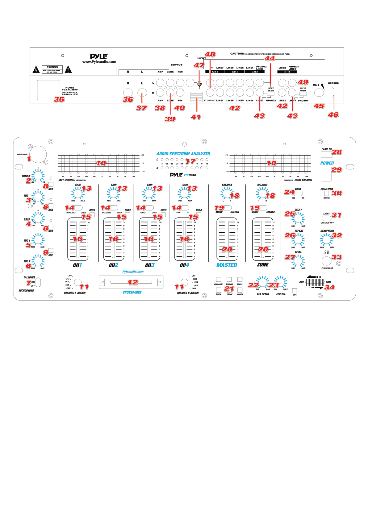
1) MIC INPUT
Microphone with balanced connector or 1/4” connector can be connected to thest inputs
2) MIC HIGH
This knob adjusts the high tone of the microphone
3) MIC MIDDLE
This knob adjusts the middle tone of the microphone
4) MIC BASS
This knob adjusts the bass tone of the microphone
5) MIC 1 LEVEL CONTROL
Let you control the MIC1 level as they enter the mix.
6) MIC 2 LEVEL CONTROL
Let you control the MIC2 level as they enter the mix.
7) MIC TALKOVER
There are Talk over, Mic On and Mic Off functions. The sound pressure level of audio from
input sources will be decreased while TALKOVER mode is selected.
Page 5

8) MIC frequency kill switches
Allows you to kill the selected frequency range instantly for interesting effects. LED lights to
indicate kill is activated.
9) MIC CUE
Use it to monitor the microphone input source
10) 10 BAND EQUALIZER
Allows you to tailor the mixer output to suit your taste or performance enviroment. Each
frequency range can be cut or boost by up to 10dB.
11) CHANNEL ASSIGN SELECTOR
Let you select the input source to be mixed by the crossfader control
12) CROSSFADER
Allow you to smooth the switch between the input sources assigned to channel A & channel B
13) GAIN CONTROL
Lets you adjust the gain of the input source.
14) CHANNEL INPUT SELECTOR
Let you to choose the input source to play for each channel
15) CHANNEL CUE
Use it to monitor the selected audio input source.
16) CHANNEL LEVEL CONTROL
Let you control mixer’s overall channel volume level
17) DUAL DISPLAY METER
Indicate the levels of left and right master channels
18) BALANCE CONTROL
Master and Zone balance control
19) MONO & STEREO SWITCH
To choose the mono or stereo output
20)Level Control
Lets you control the mixers overall ZONE or MASTER volume level, if you set up remote
speakers or DJ booth monitors.
21) 6 DIGITAL SOUND EFFECTS
Six different sound effects (ALLIEN, APPLAUSE, SIREN, CROAK, GLASS & SCREAM ) may
be added to your mix by pressing the SOUND EFFECTS CONTROL BUTTONS..
22) EFX VOLUME
The volume of the effects can be adjusted using the rotary EFX VOLUME
23) SPEED CONTROL
The pitch of the effects can be increased or decreased using the rotary SPEED CONTROL
24) ECHO ON/OFF
Turn echo on or off.
25) ECHO DELAY CONTROL
Let you adjust the delay time for echo
26) ECHO REPEAT CONTROL
Let you control the time period during which the echo is repeated
27) ECHO LEVEL CONTROL
Control the depth of the echo effect
28) USB DJ LAMP ADAPTOR
Allows you to connect 5V/500mA lamp to light the panel.
Page 6

29) POWER SWITCH
Press this button to turn on the unit after all input devices are already connected to prevent
Damage to you equipment. Turn the mixer on before you turn on the amplifier and turn off
Amplifiers before you turn off the mixer.
30) EQUALIZER ON/OFF SWITCH
Allow you to select the equalizer working situation
31) LED LIGHT CONTROL
There are 3 selector to allow you to off the lights on both the knobs and the decoration line, or
only lights on the knobs, or both the decoration line and knobs LED on.
32) HEADPHONE VOLUME CONTROL
Let you to control the volume level of headphone
33) HEADPHONE JACK
Accept headphone with 1/4” plug
34) HEADPHONE CUE/PGM CONTROL
Let you to listen simultaneously or separately to the CUE material or the active program.
35) POWER SUPPLY INPUT JACK
To connect with the power cord
36 & 37) BALANCE OUTPUT CONNECTOR
Connect the mixer to a amplifier with the balanced connector
38) ZONE OUTPUT
Connect the mixer to a second receiver or amplifier powering speakers in the DJ booth or in a
remote location.
39) RECORD OUTPUT
Connect the mixer to a second receiver or amplifier powering speakers in the DJ booth or in a
remote location.
40) MASTER OUTPUT
Connect the mixer to an amplifier
41) WINDOWS
To allow the BLUETOOTH signal transmit.
42) LINE INPUT
Let you connect most high-level audio source, such as CD players, tape deck, tuner or VCR.
43) DUAL PURPOSE STEREO INPUTS
For using a turntable with a magnetic cartidge or a high level input source
44) INPUT SELECT SWITCHES
Set these switches based on what is plugged into Phono1/Line1 and Phono2/Line 3 inputs
jacks
45) MICROPHONE JACK INPUT
To connect with a microphone 1/4” Jack
46) GROUND SCREW
For turntables
47) BLUETOOTH ANTENNA
For better performance of bluetooth signal receiving
48) BLUETOOTH OUTPUT
Connect the mixer to another unit using a RCA plugs
49) INPUT SELECT SWITCHES
Set these switches based on what is plugged into Phono1/Line1 and Phono2/Line 3 inputs
jacks
 Loading...