

Page 1
OwnerÕs Manual
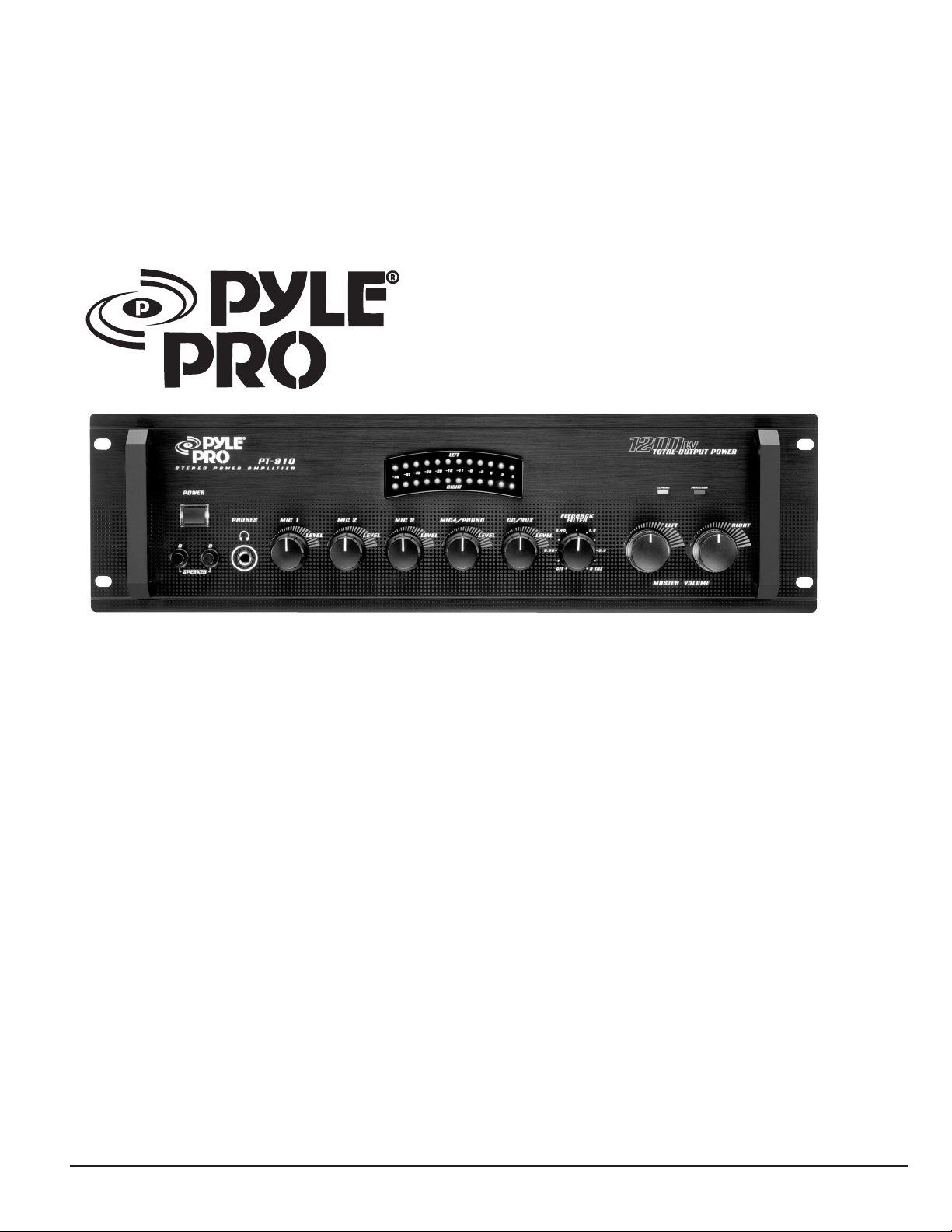
PT-910 19" Rack Mount 1200 Watt
Stereo Power Amplifier/Mixer w/70V Output
www.pyleaudio.com
Page 2

Your new Pyle Pro PT-910 1200-Watt Stereo
Power Amplifier gives you the versatility and
power you need in a professional sound system.
Its wide frequency response makes it suitable
for amplifying music or vocal program material.
It can be used in meeting halls, auditoriums,
sports events, schools, live bands, or for paging
systems.
The PT-910 can produce up to 350 watts
bridged output of clean, powerful sound with
minimum distortion.
TABLE OF CONTENTS
FEATURE AND CONTROLS
1
INSTALLATION AND GUIDELINES
2
INPUT CONNECTIONS
2
Connecting Microphones
2
Connecting a Turntable
2
Connecting an Auxiliary Sound Source
2
Connecting the MIX BUS Jack
2
Connecting an Equalizer
2
SPEAKER CONNNECTIONS
3
Connecting Speakers
3
Determining Total Speaker Impedance
3
Preparing the Speaker Wires
3
Connecting Two Speakers in Series
3
Connecting Two Speakers in Parallel
3
Unbridged Connection
3
Bridged Connection
4
Connecting The Speakers Without and With Transformers
4
POWER CONNECTIONS
4
OPERATIONS
4
Monitoring the Sound Sources
4
Listening Safely
4
Using The Feedback Filter
5
Using The Level Meter and Clipping Indicator
5
Using Speaker A/B
5
Replacing The Fuse
5
TROUBLE SHOOTING AND CARING
5
LIMITED WARRANTY
6
SPECIFICATIONS
6
Please read this manual thoroughly before you attempt to set up and use the amplifier. It contains a range of
installation suggestions as well as instructions to ensure safe usage. Installed properly, you can expect years of
trouble-free service from this product.
PYLE PRO PT-910 Amplifier OwnerÕs Manual
Page 3
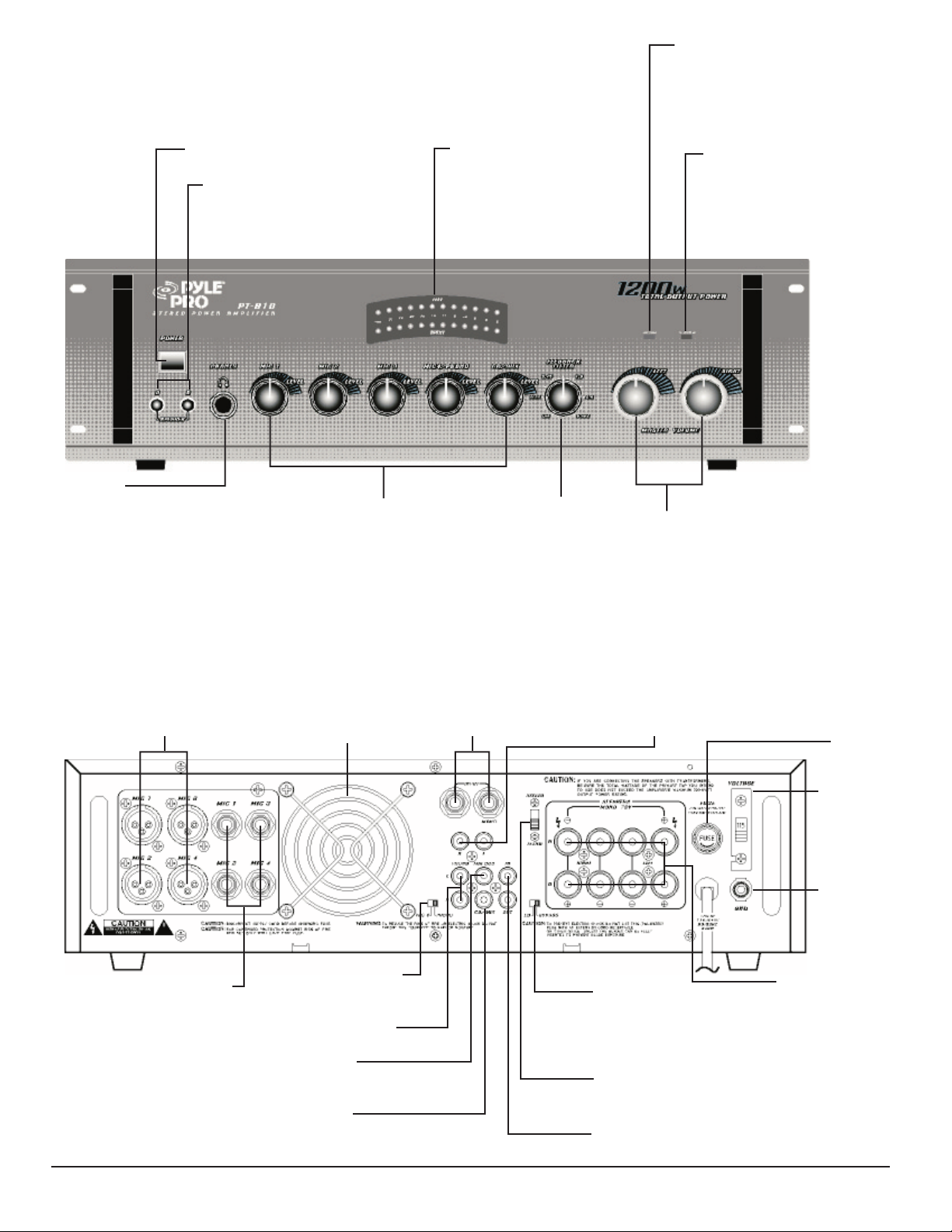
FEATURES AND CONTROLS
Illuminated Power
On/Off Lights Up
A/B Speaker Switch
Select the speakers you want to
use with the amplifier in Channel
A, Channel B, or both (for use
FRONT PANEL
with 8 ohm speaker only).
Phone Jack
Lets you connect a pair of stereo
headphones for private listening
or cueing (monitoring) sound prior
to ÒairingÓ it.
Output Power Level LED
Indicators
Indicates the total stereo
output signal level
Five Input Sources Mixing Controls
Controls the sound level for each of the
audio input sources
Mic 4 / PHONO Allows you to adjust
volume of connected Mic4 or turntable.
CD/AUX Allows you to adjust volume of
CD or auxiliary sound source.
Feedback Filter
Controls the audio
feedback.
Clip Circuit and Indicator
This special circuitry protects
the amplifier and speaker system
from being damaged by
overdriving power levels.
Indicator lights remind the user
to reduce the volume when
amplifier output is execessive.
Protection Indicator
This LED is illuminated when
a thermal overload condition
is present or if a shorted load
occurs on the amplifier
output. The amplifier resets
itself when the problem is
corrected.
Left / Right Volume
Lets you regulate the sound level of
left and right speakers.
XLR Balanced
Microphone Inputs
Connect up to four
high-impedance
microphones to your
amplifier
REAR PANEL
1/4" Unbalanced Microphone
Inputs
Connect up to four microphones
to your amplifier, via a 1/4"
unbalanced cable, for left and
right mono sound.
Cooling Fan
Cooling system is automatically
activated whenever the
amplifier is turned on. This
forced air cooling system
rapidly exhausts interior heat
to reduced operating
1/4" Stereo Input Jacks
Connect stereo input
sources (CD or DVD
player, TV, etc.) here, via
a 1/4"(balanced) audio
cable.
temperature
MIC 4/ PHONO Switch
Select MIC 4 or PHONO
input.
PHONO Input Jacks
Connect your turntable here.
MIX BUS Jack
Connect an extra amplifier if you
have multiple audio sources.
CD/AUX Jack
Connect any high-level sound source
for music or special effects.
Audio Input Jacks
Connect input sources (CD or
DVD player, TV, etc.) here, via
an unbalanced audio cable.
Match the colors on your cable
connections with the colors on
the jacks.
Fuse
110/220V
Voltage
Selector
Ground Wire
Connection
EQ/BYPASS Selector
Select EQ if you are using an
equalizer or BYPASS if you
are not using the jacks.
Speaker Terminals
Connect two sets of
speakers (Left and
Right, for A and B)
STEREO/MONO Selector
Select bridged mono input mode in
combination with a mono signal source
plugged into the left channel.
EQ IN/OUT Jacks
Connect an equalizer or other external processor.
PYLE PRO PT-910 Amplifier OwnerÕs Manual Ð 1
Page 4

INSTALLATION GUIDELINES
INPUT CONNECTIONS
The PT-910 accepts a broad range of input sources, including:
Microphones (up to 4 simultaneously)
Turntable
Compact Disc (CD) player
Cassette, Reel-to-Reel or other tape player
Radio Tuner
Equalizer
Signal Processor
Note:
¥ To prevent hum and other noise, use low-capacitance
shielded cable.
¥ This amplifier is equipped with both RCA and 6.35mm
(1/4-inch) phone jacks.
¥ Before you make any connections, be sure POWER on the front
of amplifier is out and AC power cord is not plugged in.
Connecting Microphones
You can connect up to four high- or low- impedance
microphones to the Microphone inputs on the back of the
amplifier. Each input (labeled MIC 1, MIC 2, MIC 3, and MIC
4) has a balanced and unbalanced jack. You need a
Microphone with a 6.35mm (1/4-inch) plug to connect to
an unbalanced jack or a microphone cord with a 3-pin XLR
plug to connect to a balanced jack.
Connecting an Auxiliary Sound Source
You can connect any high-level sound source, such as a CD
player, tape deck, or tuner, to the CD/AUX jack on the
back of the amplifier.
Connecting the MIX BUS Jack
You can connect another PT-910 to double the size of your
PA system. This lets you use up to eight microphones (or
six microphones and two turntables), and two auxiliary
sound sources.
Use a shielded cable with phone plugs at each end, and
connect the cable between the MIX BUS jacks of the back
of the two amplifiers. For the best results, do not use cable
longer than 1.8mm (6 feet).
Note:
¥ If your microphone's cord is longer than 6 meters (20
feet), we recommend that you connect it to a balanced
jack to reduce signal hum.
¥ If you connect a microphone to both jacks for MIC 1, MIC
2, MIC 3, or MIC 4,the microphone you connect to the
unbalanced jack has priority.
¥ If you connect a microphone to either MIC 4 jack, set MIC
4/PHONO on the back of the amplifier to MIC 4.
Connecting a Turntable
You can connect a low-level audio input source (such as a
magnetic cartridge turntable) to the L PHONO and R PHONO
jacks on the back of the amplifier. If you connect a lowlevel audio input source to the PHONO jacks, set MIC
4/PHONO on the back of the amplifier to PHONO. To avoid
a low-level hum, connect your turntable's ground wire
(usually black or green) to the GND terminal on the amplifier.
Connecting an Equalizer
You can connect an equalizer or other external signal
processor to the EQ IN and EQ OUT jacks on the back of
the amplifier.
Note:
¥ You can also connect a tape deck to the EQ OUT jack for
recording.
¥ The EQ IN/OUT jacks handle the signal from an outside
equalizer.
2 Ð PYLE PRO PT-910 Amplifier OwnerÕs Manual
Page 5

SPEAKER CONNECTIONS
Connecting Speakers
You can connect one or more 4-, 8-, or 16-ohm speakers to
the amplifier with or without transformers. To begin with,
in order to ensure equal volume from each speaker, all
connected speakers should have the same impedance.
When you use more than one speaker in the same room or
area, the proper phasing is important. Out of phase speakers
can lose up to one-half of their potential volume, and can
have a significantly decreased bass effect.
You can also bridge the amplifier's channels.
The amplifier has two channels: A and B. If you connect two
pairs of speakers, follow these guidelines:
¥ Speakers connected to the same channel (A OR B) are part
of a pair and must be of the same impedance.
¥ Speakers connected to different channels (A OR B) are not
part of a pair and can be different impedance.
Connecting Two Speakers in Series
1.Connect the right speaker's positive to the left speaker's
negative terminal.
2.Connect the left speaker's positive to the speaker output
jack's positive terminal.
3.Connect the right speaker's negative to the speaker output
jack's negative terminal.
Note:
¥ Determine the total speaker impedance of speakers you
want to connect in series by adding up the individual
impedance of all the connected speakers. If connecting
two 4-ohm speakers in series, your total speaker impedance
is 8 ohms.
Most speaker terminals are color-coded or have a mark that
indicates the terminal's polarity. Usually, terminals with
positive are red or have a plus symbol (+), and terminal with
negative polarity are black or have a minus symbol (-). Phasing
is correct when you connect + to + and - to -.
Determining Total Speaker Impedance
Before you connect any speakers to the amplifier, the total
speaker impedance must be calculated in order to avoid
damage to the amplifier.
A total speaker impedance greater than 16 ohms or less than
4 ohms can damage your amplifier or speakers.
To determine total speaker impedance, you must first decide
if you are going to connect the speakers in series, parallel,
or a series, parallel combination. If you are connecting more
than two speakers in series only or parallel only, be sure the
total impedance does not exceed the amplifier's maximum
impedance (16 ohms) or fall below the minimum impedance
(4 ohms).
A proper total impedance within the 4 to 16 ohms range can
be achieved by combining series and parallel speaker
connections.
Preparing the speaker wires
Finally, always use the shortest length of speaker wire possible
of proper gauge. Usually, 18 gauge wire is adequate for length
under 25 feet, while 16 gauge is used for greater length.
To prepare the speaker wire, remove about 1/2 inch (12.5mm)
of insulation from the end of the speaker wire you are
connecting to the amplifier. Then twist the exposed wire to
secure all of the wire strands.
Connecting Two Speakers in Parallel
1.Connect the speaker's negative terminals together and
then to the speaker output jack's negative terminal.
2.Connect the speaker's positive terminals together and
then to the speaker output jack's positive terminal.
Note:
¥ Determine the total speaker impedance of speakers you
want to connect in parallel by dividing the impedance
of one speaker by the number of speakers. If connecting
two 8-ohm speakers in parallel, divide 8 (one speaker's
impedance) by 2 (number of speakers). Your total speaker
impedance is 4 ohms.
Unbridged Connection
Use this connection if you are connecting more than one
speaker on the same channel or if you do not have highpower speakers.
1.Connect the speaker wires to the corresponding left and
right speaker's positive (+) and negative (-) terminals.
2.Connect the other end of the left and right speaker's
positive (+) and negative (-) wires to the amplifier's
corresponding SPEAKER LEFT and SPEKAER RIGHT terminals
for each channel.
To connect speaker wires to the amplifier, turn the knob
on the terminal counterclockwise until it stops, insert
the bare wire inside the space between the knob and the
amplifier, then turn the knob clockwise until it stops to
secure it.
3.Make sure STEREO/MONO is set to STEREO.
PYLE PRO PT-910 Amplifier OwnerÕs Manual - 3
Page 6

Bridged Connection,
Connecting The Speakers Without and With Transformers
IMPORTANT:
¥ For a bridged connection, DO NOT connect any speaker
wires to the BLACK SPEAKERS TERMINALS.
¥ Use only one set of connections when bridging. DO NOT
use both Channels A and B simultaneously. DO NOT mix
speakers with and without transformers simultaneously.
NOTE:
¥ SPEAKERS RIGHT (+) on the amplifier is used as a negative
(-) terminal for a bridged connection.
¥ Make sure STEREO/MONO is set to MONO.
A. Connecting The Speakers Without Transformers
Use this connection if you have high power speakers that
can handle a power output of 350 Watts.
1.Connect the speaker wires to the speaker's positive (+)
and negative (-) terminals.
2.Connect the other end of the speaker's positive (+) and
negative (-) wires to the amplifier's red SPEAKERS LEFT
and SPEAKERS RIGHT terminals.
POWER CONNECTIONS
To connect the amplifier to power, plug the attached power
cord into a standard AC outlet.
Your amplifier's fuse (located on the amplifier's back panel)
protects the amplifier from voltage surges. If the amplifier
does not work when you press POWER, check the fuse. If
it is blown, see "replacing the fuse" to replace it.
OPERATIONS
Follow these steps to use your amplifier
1.Start the input sound source.
2.Make sure LEFT and RIGHT on the front of the amplifier
are set to MIN.
3.Press in POWER to turn on the amplifier. The blue light
around the power switch and LEFT/RIGHT volume control
illuminate.
4.Rotate LEFT and RIGHT VOLUME to its mid-position.
5.One at a time, adjust MIC 1, MIC 2, MIC 3, MIC 4/PHONO,
and CD/AUX to the desired volume and balance.
NOTE:
If you hear feedback after you adjust these controls, turn
FEEDBACK FILTER clockwise until the noise disappears, see
"using the Feedback Filter".
5.Adjust LEFT and RIGHT VOLUME to the desired volume
level after you get the desired balance.
B. Connecting The Speakers With Transformers (70V
Output Capability).
The PT-910 provides 70V output when connected to
speakers with 70V transformers.
1.Connect the speaker's (+) terminal to the transformer's
secondary tap that matches the speaker's total impedance.
Located on the opposite side of the transformer, these
secondary taps are outputs, and are rated in Ohms: 4,
8, or 16.
2.Connect the transformer's PRIMARY tap to the red SPEAKER
LEFT (+) on the amplifier. Before connecting the speakers,
please be sure the total wattage of primary tap you use
does not exceed the amplifier's maximum 300 WATT
POWER RATING. These primary taps are inputs and are
rated in Watts: 1, 2.5, 10, etc.
3.Connect the speakers' (-) terminal to the transformer's
COMMON tap on the secondary side.
4.Connect the transformer's COMMON tap on the primary
side to the red SPEAKER RIGHT (-) on the amplifier.
Monitoring The Sound Sources
To monitor the sound sources, plug a pair of mono or stereo
headphones (not supplied) with a 6.35mm (1/4-inch) plug
into the PHONES jack on the front of the amplifier. Using
headphones lets you easily check and adjust he sound
source's balance.
Listening Safely
To protect your hearing follow these guidelines when you
use headphones.
¥ Set the volume to the lowest setting before you begin
listening. after you begin listening, adjust the volume
to a comfortable level.
¥ Do not listen at extremely high volume levels. Extended
high-volume listening can lead to permanent hearing loss.
¥ Once you set the volume, do not increase it. Over time,
your ears adapt to the volume level, so a volume level
that does not cause discomfort might still damage your
hearing.
4 Ð PYLE PRO PT-910 Amplifier OwnerÕs Manual
Page 7

Using The Feedback Filter
The FEEDBACK FILTER control lets you reduce or eliminate
squeal and other noise caused by feedback.
After you adjust LEFT/RIGHT volume, MIC 1, MIC 2, MIC 3.
MIC 4/PHONO, and CD/AUX, turn on the amplifier and any
connected sound source. If you hear any feedback, turn
FEEDBACK FILTER clockwise until you reduce or eliminate
the feedback.
NOTE:
The FEEDBACK FILTER control decreases feedback frequencies
by up to 12dB. If it does not eliminate the feedback, try
using a frequency equalizer to further decrease the feedback
frequencies.
Using The Level Meters and Clipping Indicator
The position of the LEDs on both row of the amplifier's
meters indicate the output power. The stronger the signal
the more LEDs illuminate. The maximum signal through the
PT-910 should cause the CLIPPING LED to blink at peak
music levels.
Using Speaker A/B
Press in SPEAKER A or SPEAKER B on the front of the amplifier
for the channel you want to listen to. Or, press in SPEAKER
A and SPEAKER B to listen to all connected speakers.
NOTE:
If you connected 4-ohm speakers to the amplifier, do not
set both SPEAKER A and SPEAKER B to IN (use 8-ohm speakers
only for this mode).
Replacing The Fuse
If the amplifier does not operate, you might need to replace
the fuse on the back of the amplifier with another 7-amp,
250-volt fuse, (not supplied).
TROUBLE SHOOTING AND CARING
Troubling Shooting
We do not expect you to have any problem with your
amplifier. But if you do, these suggestions might help.
No power
No sound
Feedback
The fuse might be blown
Sound source of speakers
not connected properly
Amplifier's LEFT/RIGHT
VOLUME, MIC 1, MIC 2, MIC
3, MIC 4/PHONO, CD/AUX
controls set to minimum
Sound source of speakers are
not connected properly
A microphone or cable might
be faulty
The speakers might wrong
impedance
The amplifier might have
shut down
FEEDBACK FILTER might
need adjustment
Microphone or speakers are
too close together
Check the amplifier's fuse and
replace it if necessary
Check all connections
Adjust the volume control to desired
setting
Check all connections
Check all microphones and cables
Make sure the speaker's wire are 18gauge(for wire length up to 7.6mm)
or 16-gauge (for length over 7.6mm).
For the best results, use the shortest
length of speaker wire possible.
Turn the amplifier off and left it cool.
Make sure the amplifier is properly
ventilated, then turn it back on.
Turn the FEEDBACK FILTER
clockwise until you reduce or
eliminate the feedback
Reposition the microphone and
speakers too close together
Caring
¥ Keep the amplifier dry. If it gets wet, wipe it dry immediately.
¥ Use and store the amplifier only in room temperature environments.
¥ Handle the amplifier carefully; do not drop it.
¥ Keep the amplifier away from dust and dirt, and wipe it with a
damp cloth occasionally to keep it looking new.
Please complete warranty card, detach and return
IMPORTANT:
¥ Let the amplifier cool down and see if it start again before
you assume a fuse needs to be replaced.
¥ Do not use a fuse with rating other than those specified
here.
Doing so might damage your amplifier.
1.Unplug the amplifier from the AC outlet.
2.Turn the fuse holder cap on the back of the amplifier and
pull out the cap to remove the fuse.
3.If the fuse is blown, replace it. Use only an identical fuse
with the proper rating. The fuse must be 7 amps.
4.Insert the fuse into the fuse holder's socket, press the
fuse holder back into the amplifier, then turn the fuse
holder's cap clockwise to tighten it.
Place
Stamp
Here
PYLE PRO Audio, Inc.
1600 63rd Street
Brooklyn, NY 11204
PYLE PRO PT-910 Amplifier OwnerÕs Manual - 5
Page 8

Limited Warranty
All PYLE PRO products are carefully constructed and tested before
shipment. Units purchased in the USA are warranted to be free of
defects in material and workmanship for one (1) year from the date of
purchase. This warranty is limited to the original retail purchaser of
the amplifier.
Should the unit fail due to factory defects in material or workmanship,
your unit will be repaired or replaced at the sole discretion of PYLE.
To obtain warranty service, you must first call our Consumer Return
Hotline at (718) 236-6948 to obtain a Return Authorization Number.
This R.A. # must appear on the outside of your package and on all
paperwork relating to your return.
When returning the unit to us for warranty service, it must be carefully
packed and shipped, prepaid, to:
R.A.#: _____________
PYLE PRO Service Center
1600 63rd Street
Brooklyn, NY 11204
You must also include the following items with your return:
¥ A copy of your sales receipt or other proof of purchase
¥ A brief letter, indicating the problem you are experiencing
¥ Include in your letter your return address, daytime phone
¥ Also include a check or money order for $20.00 for return
Our obligation under this warranty is limited to the repair or replacement
of the defective unit when it is returned to us prepaid. This warranty
will be considered void if the unit was tampered with, improperly
serviced or subject to misuse, neglect or accidental damage.
Music Products Store
Catalog Merchandiser
Sound Contractor/Installer Mail Order
Other
with the product
number and R.A. number
shipping, handling and insurance, or provide your Visa/MC
number with expiration date.
Name
Address
Model No. Serial #
Date of Purchase
Purchased at:
City, State ZIP
within 10 days.
PYE PRO AMPLIFIERS
product. To activate your
warranty, please mail this card
warranty registration card
(if available)
Thank you for purchasing this PYLE
PT-910 Specifications
Input Impedance
20K Ohms
Continuous Output Power
Stereo at 1 kHz
Stereo at 1 kHz
Bridged at 20 Hz to 20 kHz
Bridged at 1 kHz
Peak Power
120 Watts x 2 (8 ohms)
175 Watts x 2 (4 ohms)
250 Watts (8 ohms)
350 Watts (8 ohms)
1200 Watts (8 ohms)
Total Harmonic Distortion
(at 70 Watts, 8 Ohms, 1 kHz, with Band Pass Filter)
MIC (Phone Jack)
MIC (XLR Jack)
CD/AUX
PHONO
0.20%
0.20%
0.15%
0.20%
Input Sensitivity (at 0.5% THD, 1 kHz)
MIC (Phone Jack)
MIC (XLR Jack)
CD/AUX
PHONO
1.5mV
1.5mV
500mV
3mV
Signal to Noise Ratio (Input Shorted) with WTD
MIC (Phone Jack)
MIC (XLR Jack)
CD/AUX
PHONO
Frequency Response
(at 1 Watt, +/- 3dB)
MIC (Phone Jack)
MIC (XLR Jack)
CD/AUX
PHONO (RIAA 100 Hz/10 kHz)
40 Hz-20 kHz
40 Hz-20 kHz
20 Hz-30 kHz
+13dB/-13.5dB
65dB
65dB
75dB
70dB
Notch Filter Effect
Range
Depth
Noise Level (Input Short)
Speaker Impedance
300 Hz-3kHz
-12dB
0.75mV
A,B (4-16 ohms)
A+B (8-16 ohms)
Bridge(8-16 ohms)
Power Requirement
Power Fuse
Dimensions (HWD)
120V AC 60Hz
7 Amps/250 volt
136 x 482 x 367 mm
(5 3/8 x 19 x 14 7/16 inches)
Weight
NOTE:
¥ Specifications are typical; individual units might vary.
¥ Specifications are subject to change and improvement without
notice.
¥ Actual product may vary from the product images in this document.
27 lbs (12.3kgs)
PYLE PRO PT-910 Amplifier OwnerÕs Manual Ð 6
 Loading...