

Page 1

www.PyleAudio. com
PT-610
PT-610
PT-610
19'' Rack Mount 600 Watt Power Amplifier/
Mixer w/ 70V Output & Mic Talkover
USER MANUAL
Page 2

Your new Pyle Pro PT-610 600 Watt P.A. Amplifier gives you the power and
versatility you need in a professional sound system. The amplifier’s wide
frequency response makes it suitable for amplifying music or vocal program
material. It can be used for live bands, office paging systems, public
announcement systems, or a variety of other installations.
TABLE OF CONTENTS
2-4. Features and contents
4. Installation Guidelines
4. Connecting a CD or tape player or tuner
4. Connecting an additional CD sound source
5. Connecting an equalizer or signal processor
5. Connecting microphones
6. Speaker Connections
6. Connector options
7. System 1: Single speaker system
7. System 2: Two speakers in series
8. System 3: Two speakers in parallel
8-9. System 4: Four speakers in series/parallel
10.System 5: Connecting speakers with transformers
11.Using headphones
11.Connecting to AC power
11.Mounting the amplifier
11.Turning the amplifier on
12.Using the power meter
12.Using the master volume control
12.About the internal clip circuitry
12.About the internal protection circuitry
13.About the feedback filter
13.Caring for your PT610 Amplifier
13.Replacing a fuse
14.Specifications
Please read this manual thoroughly before you attempt to set up and use the
amplifier. It contains a range of installation suggestions as well as
instructions to ensure safe usage. Installed properly, you can expect years of
trouble-free service from this product.
1
Page 3

FEATURES AND CONTROLS
FRONT PANEL
1 2 3 4 6
9
78
5
REAR PANEL
11 12 13 14 15 16 17 19
10
18
1.Main Power On/ Off Switch
The amplifier is switched ON or OFF by using the switch.
2.Phone Jack
Lets you connect a pair of stereo headphones for private listening or
cueing (monitoring) sound prior to “airing” it.
3.Five Input Sources Mixing Controls
Control the sound level for each of the audio input sources.
4.Feedback Filter
Control the audio frequency.
5.Master Volume
Lets you adjust the overall sound level.
6.3. 5mm AUX Input Jack
Lets you easily connect the computerized MP3 devices (player) sources,
such as PC, Laptop, Walkman, iPod and Cell Phone.
7.Protection Indicator
This LED is illuminated when a thermal overload condition is present.
2
Page 4

8.Clip Circuit and Indicator
This special circuitry protects the amplifier and speaker system from
being damaged by overdriving power levels. Indicator lights remind
the user to reduce the volume when amplifier output is excessive.
9.Power Meter
Indicate the output signal level.
10.BYPASS/ EQ Switch
Sets the switch to the EQ position, you can connect an equalizer.
Sets the switch to the BYPASS position, the equalizer has no effect
on your system’s sound.
11.EQ IN/ OUT RCA Jacks
To connect an equalizer to these jacks, you can have the effect on
your system’s sound.
12.LINE/AUX RCA Inputs
To connect any high-level sound source, such as a CD player, tape
deck, or tuner to the amplifier’s LINE/AUX jacks.
13.AUX/MIC4 Switch
If you connect a low level audio input source to the AUX jacks, set
AUX/MIC4 to the AUX position.
If you set AUX/MIC4 to the MIC4 position, you can use MIC4.
14.Four Microphone Inputs
Allows you connect up to four Microphones by balanced XLR type
sockets or unbalanced 6.35mm type sockets.
15.Speaker Terminals
Connect your speaker system to these terminals. You can connect
one or more 4ohm, 8ohm, 16ohm speakers to the amplifier,
with or without transformers. To ensure equal volume from each
speaker, all the connected speakers should have the same impedance
rating.
16.GND Screw Terminal
17.Power Fuse (3A, 250V)
It is the power supply fuse, it protects the amplifier from unwanted
voltage surges and the other abnormal operating conditions.
18. AC IN
Connect to AC 110V/60Hz or 220V/ 50Hz power supply.
3
Page 5
19. Voltage Switch
The unit has a selectable input voltage from 115V/ 60Hz which is the
standard in the USA and Canada. You can also switch the input
voltage to 230V/50Hz for European operation. Please make sure
the switch is in the proper position before operating, otherwise
severe damage will result not covered by the warranty.
INSTALLATION GUIDELINES
Input connections
The PT610 accepts a broad range of input sources, including:
Compact Disc (CD) Player
Cassette, Reel-to Reel or other tape player
Radio Tuner
Microphones ( up to 4 simultaneously)
Equalizer
Signal Processor
Connecting front AUX jack
Permit you to connect one AUX MP3 devices with 3. 5mm plug.
Connecting a CD or tape player or tuner
In a normal installation, one would use the LINE JACK for connecting
a CD player, tape player or tuner.
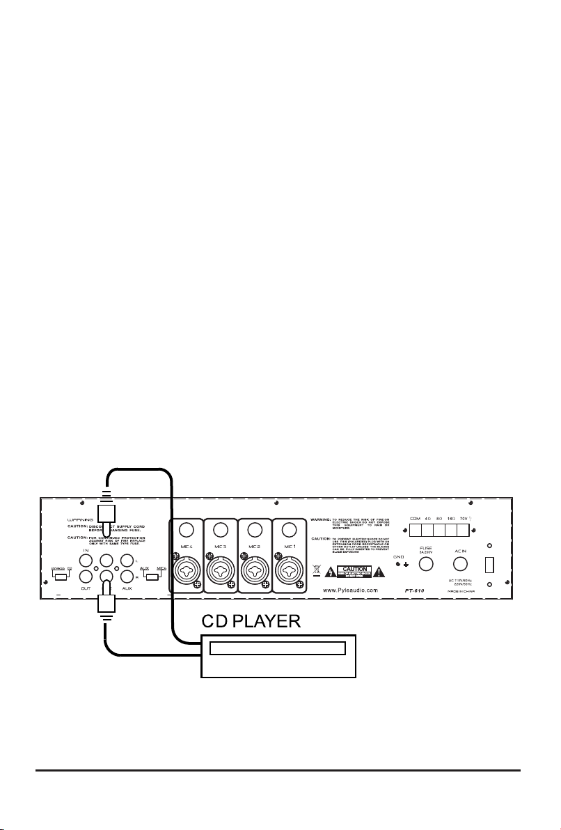
Connecting an additional CD sound source
In this situation, use the AUX JACK, and set the MIC4/ AUX
SELECTOR switch to the AUX position.
4
Page 6

“AUX”
CD PLAYER
Connecting and equalizer or external signal processor
Connect the processor’s OUT to the amplifier’s IN, and the processor’s
IN connector to the amplifier’s OUT.
IN
EQ OR MIXER
Connecting microphone
The MIC IN jacks permit you to connect up to 4 low impedance
microphones. The microphones can be used with either a 6.35mm
plug, or a 3-pin XLR type plug.
5
Page 7

6.3 mm or 3-pi n XLRJack
MIC
Speaker connections
One or more speakers ( 4, 8 or 16 Ohm) speakers can be connected
to the amplifier with or without transformers. However, before you
connect any speakers to the amplifier, the total speaker impedance
must be calculated in order to avoid damage to the amplifier. A total
speaker impedance greater than 16 Ohms or less than 4 Ohms can
cause this damage to occur.
To begin with, in order to ensure equal volume from each speaker,
all connected speaker should have the same impedance.
A proper total impedance within the 4 to 16 Ohm range can be
achieved by combing series and parallel speaker connections. Please
see the diagram which follow which explain how to accomplish this.
Finally always use the shortest length of speaker wire possible of
proper gauge. Usually 18 gauge wire is adequate for lengths under
25 feet, while 16 gauge is used for greater lengths.
Connector options
The PT- 610 offers several different connection points for speaker
hookups. These include screw terminals, a 6.3mm jack, and a pair
of banana plug connectors.
It is not proper or recommended to connect all the speaker outputs
simultaneously. In addition, please note that when the 6.3mm jack
is used, all the screw terminal and RCA signal outputs are
disconnected.
6
Page 8

System 1: Single speaker system
1.Connect the speaker (-) terminal to the amplifier COMMON terminal.
2.Depending on the speaker being used, connect the speaker (+ )
terminal to the amplifier 4 Ohm, 8 Ohm or 16 Ohm amplifier terminal.
THISEXAMPLE SHOWS A
4 OHM SPEAKER
System 2: Two ( or more) speakers in series
1.Connect the LEFT SPEAKER ( -) to the amplifier COMMON terminal.
2.Connect the LEFT SPEAKER ( +) to the RIGHT SPEAKER ( - ).
3.Connect the RIGHT SPEAKER ( + ) to the amplifier’s 4 Ohm, 8 Ohm
or 16 Ohm terminal, depending on the TOTAL IMPEDANCE of the two
speakers.If each speaker has an impedance of 8 Ohms, the total speaker
impedance in this series configuration is 16 Ohms.
NOTE: Additional speakers may be included in series, but it is
necessary to calculate total impedance, and connect the speaker
circuit to a terminal of appropriate impedance. For example, if three
speakers of 4 Ohms are used, total impedance is 12 Ohms-You
should connect to the 16 Ohm terminal.
7
Page 9

System 3: Two ( or more) speakers in parallel
1.Connect the LEFT SPEAKER ( -) to the RIGHT SPEAKER ( - ).
2.Connect both the LEFT SPEAKERS ( - ) and RIGHT SPEAKER ( - )
to the amplifier COMMON terminal.
3.Connect the LEFT SPEAKER ( +) to the RIGHT SPEAKER ( + ).
4.Connect both the LEFT SPEAKER ( -) to the RIGHT SPEAKER ( + )
to the amplifier 4 Ohm, 8 Ohm or 16 Ohm terminal, depending on
the TOTAL IMPEDANCE of the two speakers. If each speaker has
an impedance of 8 Ohms, the total speaker impedance in this
parallel configuration is 4 Ohms.
System 4: Four speakers in series/parallel combination
1.Group the four speakers in two pairs.
2.Connect one pair of speakers in series (see system 2, above) .
Note total impedance in chart below.
3.Connect one pair of speakers in parallel (see system 3, above).
Note total impedance in chart below.
4.Connect the speakers’ (-) terminals to the amplifier COMMON
terminal.
5.Connect the speakers’ (+) terminals to amplifier’s 4 Ohm, 8 Ohm
or 16 Ohm terminal, depending on the TOTAL IMPEDANCE of the
four speakers. See the chart below for some sample system
suggestions:
8
Page 10

Series/parallel variations
Although the description above is for combining a series pair and a
parallel pair in a parallel hookup, you may also elect to combine two
series pairs in parallel hookup. Simply be sure you have properly
calculated the total impedance, and attach the (+) speaker circuit wire to
the proper amp terminal. For example, if you use two pairs of
8 ohm speakers in series each pair, the impedance for each pair is
16 Ohms. Connected in parallel to the amp terminals, the TOTAL
impedance is 8 Ohms, so you should connect these to the 8 Ohm
terminal.
9
Page 11

System 5: Connecting speakers with transformers
1.Locate the input taps on your transformer. These taps are on one side of
the transformer and are rated in watts: 10, 5, 2.3, 1.25 or 0.62. Usually,
each speaker in a system uses the same wattage tap.
Connect the selected tap to the amplifier 70V RMS terminal.
If you wish a particular speaker to have a higher volume level, connect the
wire from 70V RMS to a higher wattage tap on the transformer.
2.Connect the transformer’s COMMON tap to on the primary side to the
amplifier COMMON terminal.
3.Connect the speaker’s (+) terminal to the transformer’s secondary tap
that matches the speakers’ total impedance. Located on the opposite side
of the transformer, these secondary taps are outputs, and are rated in
Ohms: 4, 8, or 16.
4.Connect the speakers’ (-) terminals to the transformer’s COMMON tap on
the secondary side.
Note: Before connecting the speakers, please be sure the total wattage of
the primary tap you use does not exceed the amplifier’s maximum 100 WATT
power rating.
Also: Avoid, where possible, multiple connections to the 70V RMS and
COMMON terminals.
INPUT
TAPS
1W
OUTPUT
TAPS
16 OHMS
2.5W
10W
COM
8 OHMS
4 OHMS
COM
FOUR OHM SPEAKER SHOWN
10
Page 12

Using headphones
To listen privately, or to monitor sound sources, connect a pair of low
impedance stereo headphones (not supplied) with a 6.35 mm plug into
the PHONES jack on the amplifier front panel.
Please listen safely. Follow these recommendations:
Do not listen at extremely high volume levels. Extended, high-volume
listening can lead to permanent hearing loss.
Always start with the volume control set to LOW level BEFORE you put
the headphones on. Then gradually increase the volume as necessary.
Once you set the volume, do not increase it. Over a period of time, your
ears adapt to the volume level, so a volume level which does not cause
immediate discomfort may still be actually damaging your hearing.
Connecting to standard AC power
After making all other connections, set the POWER switch to OFF
position. Then connect the power cord to a standard AC outlet.
Mounting the amplifier
The PT610 is designed to accept standard rack mounting installations.
Two slots on each end of the front panel make it suitable for such an
installation.
Tightly secure four mounting screws (not supplied) through these four
slots and into your standard electronics equipment rack.
Turning the amplifier on
1.Turn on the audio input source equipment which is connected to the
amplifier INPUT jacks.
2.Set all volume levels (Master, Mic 1-3, Mic 4/AUX and Line) to their
minimum level settings.
3.Push in the power switch to turn the amplifier on.
4.Adjust the controls of MIC 1-3, Mic4/AUX and LINE to the desired
volume and balance.
11
Page 13

Using the power meter
The meter pointer position indicates the amplifier output power. For ease
of reading in dark environments, the meter is illuminated.
Using the Master Volume control
The Master Volume control increases or decreases output level gain. To
obtain best performance with the least distortion, be sure to adjust the
output level so that the meter’s pointer does not continually exceed the
right extreme of the meter’s range.
CAUTION! Setting output level too high can overdrive the amplifier,
causing permanent damage.
About the internal clip circuitry
Special clip circuitry incorporated into the PT610’ design protects the
amplifier and speaker system from being damaged from overdriving
power.
Under normal conditions, the amplifier’s clip indicator will flicker as the
output power momentarily exceeds the level as set by the output level
gain selector.
However, under excessive output conditions, the clip indicator lights
remain on continuously, alerting you that the special clip circuitry has
become active. When this occurs, you should simply reduce the output
power level by rotating the Master Volume control counterclockwise.
About the internal protection circuitry
In the event that the amplifier becomes excessively hot due to power
overload, the built-in circuitry will temporarily interrupt the amplifier’s
power.
Should this occur, please turn off the power and let the amplifier cool
down for about 15 minutes. Correct whatever situation caused the
overload, and then turn the power back on.
12
Page 14

About the feedback filter
The PT610 features an anti-feedback filter, which can help to reduce
or eliminate squealing or other noise caused by acoustic feedback.
To engage this feature, after you turn on the amplifier, turn the front
panel-mounted FEEDBACK control counterclockwise. This control
decreases the feedback frequencies by up to 12DB.
Caring for your PT610 Amplifier
Your Pyle Amplifier is an example of superior design and craftsmanship.
The following suggestions will help you care for your amplifier so you
can enjoy years of use.
Keep the amplifier dry. If it gets wet, wipe immediately. Use the amplifier
only in well-ventilated installation. Handle the amplifier gently and
carefully- do not drop! Keep the amplifier away from dust and dirt. Wipe
occasionally with a damp cloth to keep it looking new. Do not use harsh
chemicals, solvents or detergents!
Replacing a fuse
This amplifier uses a 250V, 3A fuse for protection from power surges
and short circuits. If the amplifier suddenly shuts down and will not turn
on, it is likely that this fuse has blown.
To replace the fuse:
1.Locate the fuse holder on the rear of the cabinet and unscrew the fuse
compartment cap.
2.Remove the old fuse and replace it with an identical, serviceable fuse.
CAUTION: Never use a fuse with a higher rating!
3. Replace the fuse compartment cap.
13
Page 15

PT 610 Specifications
Output Power at THD 2%, 8-Ohm Load, 1 kHz
Maximum Power, 8-Ohm Load
Maximum Output, 4-Ohm Load
THD at 70W, 8-Ohm Load, 1 kHz, w/bandpass filter
MIC (phone/XLR jack)
AUX
Line
Frequency Response (at 1 Watt, +/- 3 dB)
MIC (phone/XLR jack)
AUX
Line
Input Sensitivity (at 2% THD, 1 kHz)
MIC
AUX
Line
Signal-to-Noise Ratio
MIC
AUX
Line
100W
200W
600W
0.35%
0.20%
0.20%
75 Hz–20 kKz
60 Hz–20 kHz
60 Hz–20 kKz
1 mV
150 mV
150 mV
60 dB
73 dB
73 dB
Notch Filter Effect
Range
Depth
Noise Level (with inputs shorted)
Power Requirement
Power Fuse
Dimensions H x W x D, inches
(mm)
Weight, lbs (kg)
300 Hz–3 kHz
–12 dB
0.75 mV
120V AC, 60 Hz
3A/250V
4 3/16 x 19 x 12
(100 x 481 x 303)
22.3 (10.1)
14
Page 16

 Loading...