

Page 1
Warning: Some TVrequire two people tolift, as weare notresponsible forany
personal injury orproduct damage dueto mishandling.
Fig 3a Fig 3b
Item No.:PSW112Item No.:PSW112
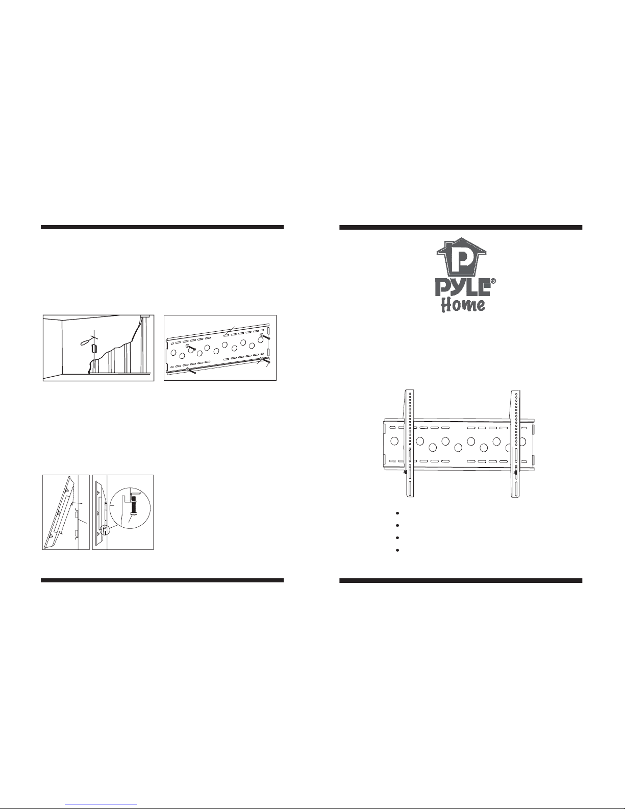
Step 3: Hangingdisplay
Firstly lift thebracket mounteddisplay overthewall mount.And then hookthe
brackets over thetop ofthe wall mount.Rotate thedisplay let thebottom of the
brackets hook overthe bottomof wall mount, as shown in Fig.3a. Thenput safe
bolts into thebottom of the brackets andlock it, as shown inFig.3b.
Fig 2b
Fig 2c
-8-
Multifunctional double deck wall mount
Fixed Flat Panel TV Bracket
INSTALLATION GUIDE
IMPORTANT: If don’t understand about right install ways, please
consult to normal installing specialist.
Easy installing:Just hang up the display
Safety: locking by spining bolt on the bottom
Max loadcapacity:75kg(165lbs
TV sizerange: 36 ~55
,
)
""
Brick, Concrete andStone wall(Fig2c):
Using the wallmount as template to mark6 holes locationon the wall. There holesare
located at thetop rowof the slots and threemore arelocated at the bottom row. The
outer holes mustbe fall to the leftand right ofthe two holes in the middle of the
mount. Please makesure theseholes arelevel and at least 6”between any twolines.
Pre-drill these holes with a 10mm drillbit to atleast 80mm deep hole. InsertWall
anchors(P) into eachof these holes. Attach thewall mount tothe wall using 6 Long
bolts(O) and washers(Q).
2,3
4
1
O
1
Q
Page 2
Hardware List:Hardware List:
M× mm4 40 bolt
M5×40mmbolt
M6×40mmbolt
M8×40mmbolt
4
4
4
4
4
6
I
J
K
L
M
N
O
P
Q
R
S
6
8
8
6
Square washer
Long bolt
Wallanchor
Long bolt washer
9/16 Spacer"
1/2 Spacer"
ID Description
1
2
A
3
B
C
1
1
4
1
4
4
Wallmount
Left bracket
Right bracket
M4 mm×12 bolt
Mmm5×12 bolt
M× mm6 12 bolt
M× mm8 12 bolt
M× mm4 25 bolt
M× mm5 25 bolt
M6× mm25 bolt
M× mm8 25 bolt
Qty
D
4
4
4
4
4
4
E
F
G
H
42
Safe bolt
b
15 degree
viewing angle
eyelevel
a
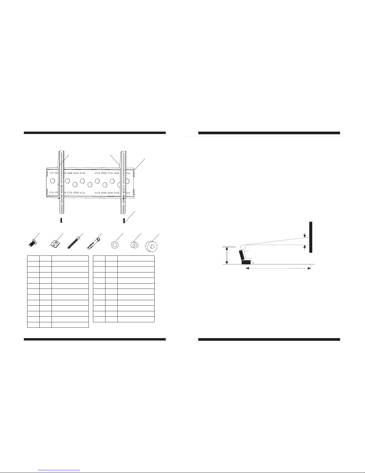
After determining theheight of stand, follow theinstallation instructions inbelow
to install wallmount to different kinds ofwall -wooden, brick, concrete andstone.
Using a awl or nail to make wherethe nailsare located,as shown as fig.2b. Distance
between two nails for fixingwall mount must not lessthan 12”. Pre-drill these holes
with a 5mmdrill bit to a at least 80mmin deep hole.Please makesure these holesare
level and locatedat center. Use wallmount asa template tomark the location of other
three holes anddrill thesame holes. Fix the wallmount to the wall with 4 long bolts(O)
and washers(Q).
Woodenwall(Fig 2b):
-2-
-7-
Fig 2a
A-M
Q
N
1
2
3
4
P
O
R
1/4 -20×5/8 bolt""
ID
Description
Qty
Step 2: mount to wall
First, determine the height of stand
The best height of standis parallel to eyelevel ofa person whositting on a couch.
Normally,the horizontaldistance of eyelevel is about 4’ from groundlevel.
The following twoconditions arefor determining the perfect height of stand:
1) the distance between wall and couch(Fig 2a).
2) the distance of eyelevel fromground levelplus the distancemeasured from
eyelevel of aperson sitting on couch withviewing angle of15 (Fig 2a).
For example:
1) the distance of ‘a’ is 5’-7’, the distanceof ‘b’ isabout 1’
2) the distance of ‘a’ is 8’-13’, the distanceof ‘b’ isabout 3’
3) the distance of ‘a’ is 14’-17’, the distanceof ‘b’ isabout 4’
The perfect heightof stand centre will beanywhere withinb, whereyou feel
comfortable for viewing.
°
AttachStep 2: Attachmount to wall
S
Page 3
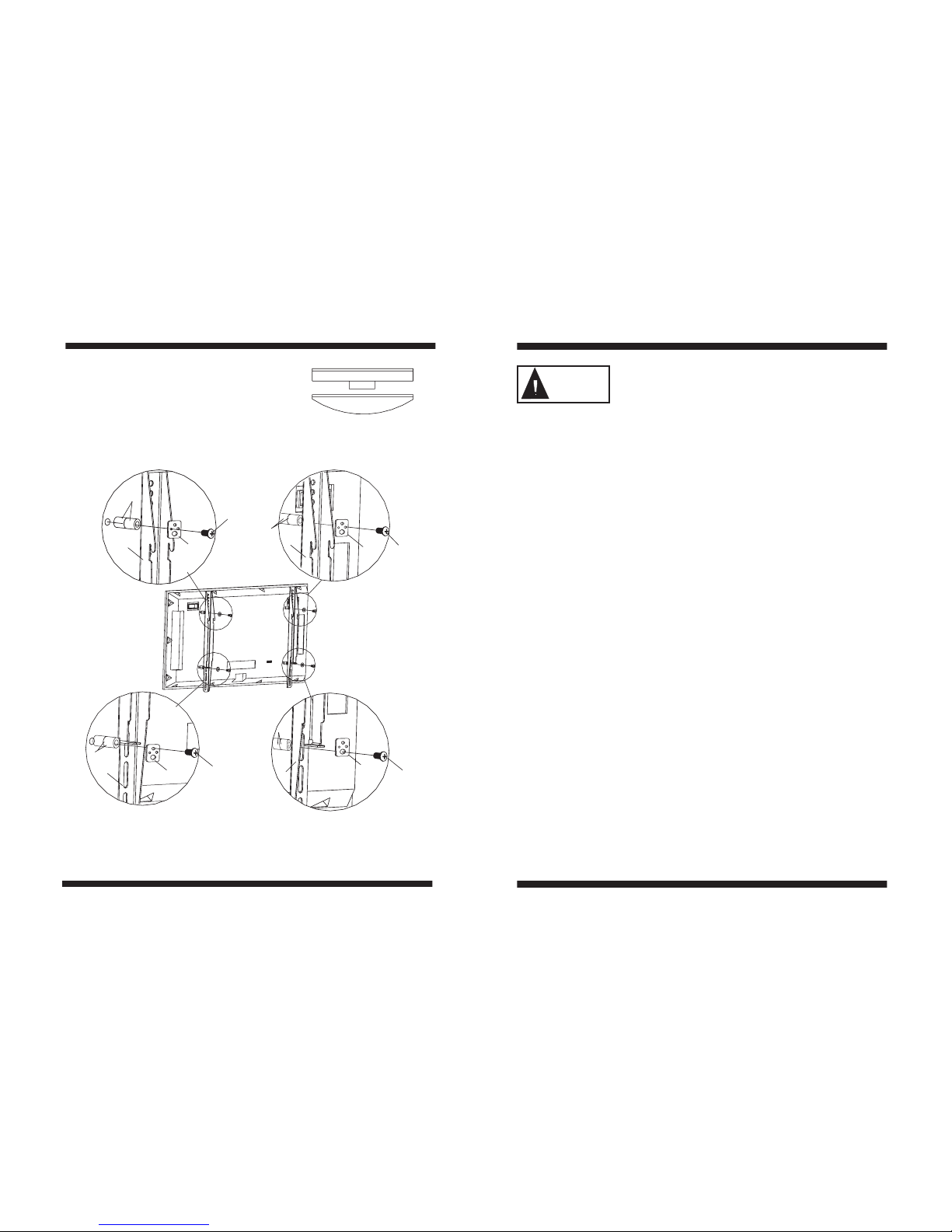
Fig 1c
-6-
-3-
WARNING
Step 1: Attachbracket toTV
CheckyourTVmanualtoconfirmthediameterofbolttobeusedorchoosean
appropriate bolt according to size,height and position of the holes on yourTV. See
pages 4-6 ofthese instructions for examples.
For correct installing, makesure that hookof every bracketmust facingdown. Use
selected bolt, spacersand washer for installing bracketat the back of display.
Adjust two bracketsto equal heights and level. Once aligned, tightly secure the
bolts.
Don't force thebolt intothe hole, which will cause a damage of
equipments and injureof person.Don't use electric drill to fasten any bolts.
IMPORTANT:
M5 Fig bitM4 Fig bit
We are not responsible for any personal injury or product damagedue tomishandling,
incorrect mounting, incorrect assembly or incorrect use of this product.
The suppliedwall mounting hardware is not for use on steel stud walls or cold
cinder blockwalls. If youare uncertain about the nature of your wall, please consult a
qualified contractor. If the hardware you required is not included please contact your
local hardware store or the nearest Circuit City Stores.
Note:
3. For display with protrudingHDTV tuneor deeply
curved backs(Fig b), two9/16” spacers(R)or two
½” spacers(S) should be used.Stack twospacers
and then installthem between display and the
bracket. As shownin Fig1c.
Fig b
M8 Fig bit
M6 Fig bit
I
3
N
R
2
J
N
R
3
K
N
R
L
N
2
S
Caution:This ProductLCD /PlasmaWall Mount Bracket isintended foruse only
with themaximum weights indicated.See apparatus instructions.Use with products
heavier thanthe maximum weightsindicated may result ininstability causing possible
injury .
Page 4
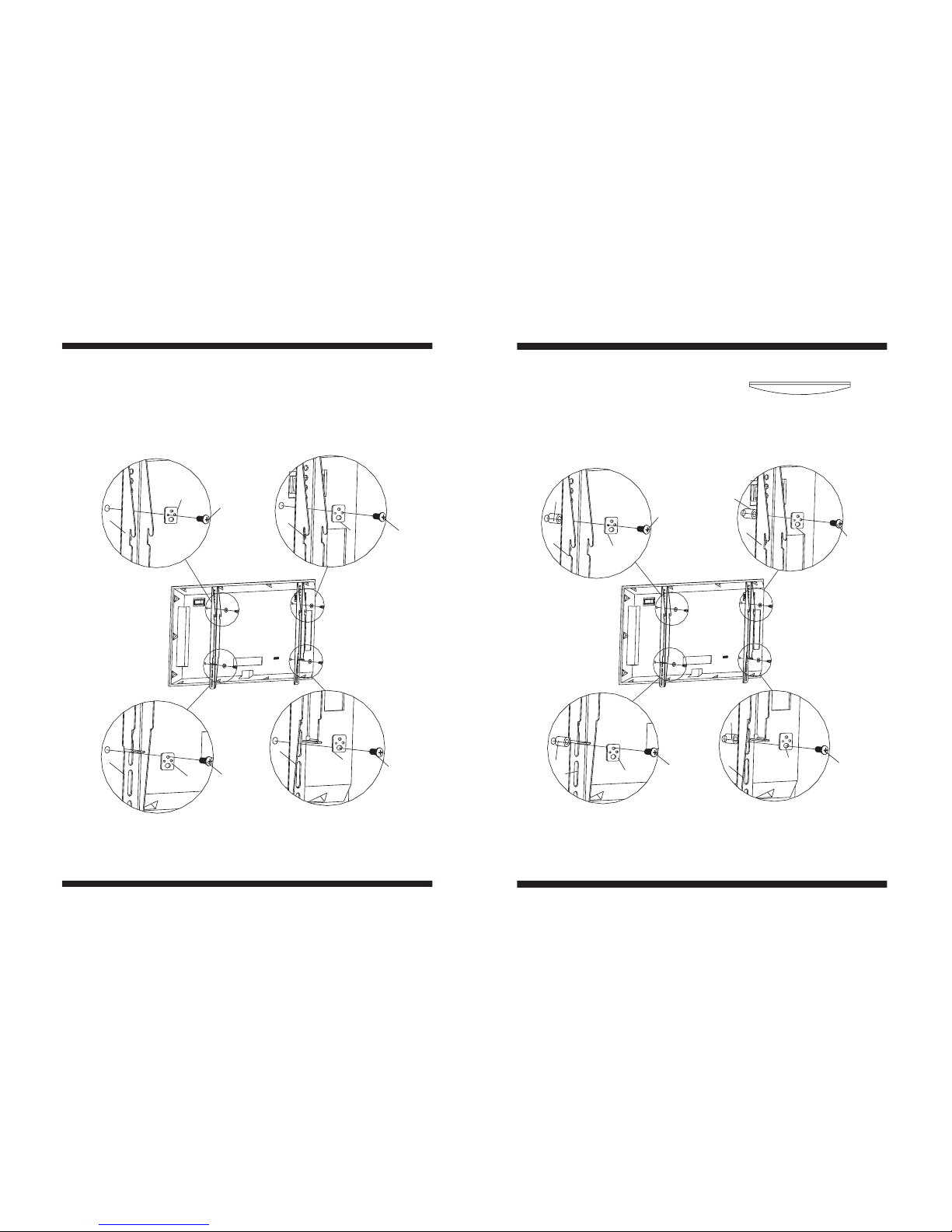
Fig 1a
M4 Fig bit M5 Fig bit
Fig 1b
2. Some displayshave curved backs with
recessed mounting lands(Fig.a). It will
require the use of spacer. For this display,
install a 9/16”spacer(R) or ½”spacer(S)
between display and the bracket. As
shown in Fig1b.
Fig a
-4-
-5-
M5 Fig bitM4 Fig bit
Following examples showshow to use bolts, spacersand square washers.
1.Somedisplays have vertical backs. No spacer is required.Install thebracket directly
to the backof display by using boltsand square washersprovided. Asshown in Fig.1a.
M8 Fig bitM6,1/4 -20 5/8 Fig bit""
A
3
N
D
C,M
3
2
N
N
2
B
N
M8 Fig bitM6 Fig bit
E
3
N
R
2
F
N
R
G
N
3
R
H
N
2
S
 Loading...